EP3292827A1 - Debrider mit mehreren spülungsöffnungen - Google Patents
Debrider mit mehreren spülungsöffnungen Download PDFInfo
- Publication number
- EP3292827A1 EP3292827A1 EP17190526.8A EP17190526A EP3292827A1 EP 3292827 A1 EP3292827 A1 EP 3292827A1 EP 17190526 A EP17190526 A EP 17190526A EP 3292827 A1 EP3292827 A1 EP 3292827A1
- Authority
- EP
- European Patent Office
- Prior art keywords
- irrigation
- hollow tube
- orifices
- orifice
- tissue
- Prior art date
- Legal status (The legal status is an assumption and is not a legal conclusion. Google has not performed a legal analysis and makes no representation as to the accuracy of the status listed.)
- Granted
Links
Images

Classifications
-
- A—HUMAN NECESSITIES
- A61—MEDICAL OR VETERINARY SCIENCE; HYGIENE
- A61B—DIAGNOSIS; SURGERY; IDENTIFICATION
- A61B17/00—Surgical instruments, devices or methods
- A61B17/32—Surgical cutting instruments
- A61B17/3205—Excision instruments
- A61B17/3207—Atherectomy devices working by cutting or abrading; Similar devices specially adapted for non-vascular obstructions
- A61B17/320783—Atherectomy devices working by cutting or abrading; Similar devices specially adapted for non-vascular obstructions through side-hole, e.g. sliding or rotating cutter inside catheter
-
- A—HUMAN NECESSITIES
- A61—MEDICAL OR VETERINARY SCIENCE; HYGIENE
- A61M—DEVICES FOR INTRODUCING MEDIA INTO, OR ONTO, THE BODY; DEVICES FOR TRANSDUCING BODY MEDIA OR FOR TAKING MEDIA FROM THE BODY; DEVICES FOR PRODUCING OR ENDING SLEEP OR STUPOR
- A61M3/00—Medical syringes, e.g. enemata; Irrigators
- A61M3/02—Enemata; Irrigators
- A61M3/0279—Cannula; Nozzles; Tips; their connection means
- A61M3/0283—Cannula; Nozzles; Tips; their connection means with at least two inner passageways, a first one for irrigating and a second for evacuating
-
- A—HUMAN NECESSITIES
- A61—MEDICAL OR VETERINARY SCIENCE; HYGIENE
- A61B—DIAGNOSIS; SURGERY; IDENTIFICATION
- A61B17/00—Surgical instruments, devices or methods
- A61B17/24—Surgical instruments, devices or methods for use in the oral cavity, larynx, bronchial passages or nose; Tongue scrapers
-
- A—HUMAN NECESSITIES
- A61—MEDICAL OR VETERINARY SCIENCE; HYGIENE
- A61B—DIAGNOSIS; SURGERY; IDENTIFICATION
- A61B17/00—Surgical instruments, devices or methods
- A61B17/32—Surgical cutting instruments
- A61B17/320016—Endoscopic cutting instruments, e.g. arthroscopes, resectoscopes
- A61B17/32002—Endoscopic cutting instruments, e.g. arthroscopes, resectoscopes with continuously rotating, oscillating or reciprocating cutting instruments
-
- A61M1/0058—
-
- A—HUMAN NECESSITIES
- A61—MEDICAL OR VETERINARY SCIENCE; HYGIENE
- A61M—DEVICES FOR INTRODUCING MEDIA INTO, OR ONTO, THE BODY; DEVICES FOR TRANSDUCING BODY MEDIA OR FOR TAKING MEDIA FROM THE BODY; DEVICES FOR PRODUCING OR ENDING SLEEP OR STUPOR
- A61M1/00—Suction or pumping devices for medical purposes; Devices for carrying-off, for treatment of, or for carrying-over, body-liquids; Drainage systems
- A61M1/84—Drainage tubes; Aspiration tips
-
- A—HUMAN NECESSITIES
- A61—MEDICAL OR VETERINARY SCIENCE; HYGIENE
- A61B—DIAGNOSIS; SURGERY; IDENTIFICATION
- A61B17/00—Surgical instruments, devices or methods
- A61B17/32—Surgical cutting instruments
- A61B17/3205—Excision instruments
- A61B17/3207—Atherectomy devices working by cutting or abrading; Similar devices specially adapted for non-vascular obstructions
- A61B17/320758—Atherectomy devices working by cutting or abrading; Similar devices specially adapted for non-vascular obstructions with a rotating cutting instrument, e.g. motor driven
-
- A—HUMAN NECESSITIES
- A61—MEDICAL OR VETERINARY SCIENCE; HYGIENE
- A61B—DIAGNOSIS; SURGERY; IDENTIFICATION
- A61B17/00—Surgical instruments, devices or methods
- A61B17/32—Surgical cutting instruments
- A61B17/320016—Endoscopic cutting instruments, e.g. arthroscopes, resectoscopes
- A61B17/32002—Endoscopic cutting instruments, e.g. arthroscopes, resectoscopes with continuously rotating, oscillating or reciprocating cutting instruments
- A61B2017/320032—Details of the rotating or oscillating shaft, e.g. using a flexible shaft
-
- A—HUMAN NECESSITIES
- A61—MEDICAL OR VETERINARY SCIENCE; HYGIENE
- A61B—DIAGNOSIS; SURGERY; IDENTIFICATION
- A61B17/00—Surgical instruments, devices or methods
- A61B17/32—Surgical cutting instruments
- A61B2017/320064—Surgical cutting instruments with tissue or sample retaining means
-
- A—HUMAN NECESSITIES
- A61—MEDICAL OR VETERINARY SCIENCE; HYGIENE
- A61B—DIAGNOSIS; SURGERY; IDENTIFICATION
- A61B2217/00—General characteristics of surgical instruments
- A61B2217/002—Auxiliary appliance
- A61B2217/005—Auxiliary appliance with suction drainage system
-
- A—HUMAN NECESSITIES
- A61—MEDICAL OR VETERINARY SCIENCE; HYGIENE
- A61B—DIAGNOSIS; SURGERY; IDENTIFICATION
- A61B2217/00—General characteristics of surgical instruments
- A61B2217/002—Auxiliary appliance
- A61B2217/007—Auxiliary appliance with irrigation system
Definitions
- the present invention relates generally to medical debriders, and particularly to methods and systems for irrigation in a debrider.
- Medical debriders are used in various procedures, such as in sinuplasty procedures carried out in a patient nose. Examples of prior art techniques for using debriders are provided below.
- U.S. Patent 6,371,934 whose disclosure is incorporated herein by reference, describes an irrigation system for removing arthritis-causing fragments from a joint in the body, the system includes a handpiece and a tip that is connectible to the handpiece.
- the tip includes a shaft that forms an irrigation lumen, and a debrider disposed along at least a part of the shaft.
- the debrider defines a substantially planar debriding surface for debriding the interior surfaces of the joint.
- the debrider may include a plurality of bristles extending from the shaft to the debriding surface.
- U.S. Patent Application Publication 2014/0148835 whose disclosure is incorporated herein by reference, describes a bendable medical device that includes a distal housing, an outer support tube, an inner drive tube, a coupler and a commutator portion.
- the coupler and commutator portion serve to axially constrain a distal end of the inner drive tube during bending, and to supply fluid for lubricating, cooling and irrigating the distal end of the device.
- U.S. Patent 6,183,433 whose disclosure is incorporated herein by reference, describes a surgical suction cutting instrument with internal irrigation.
- the instrument includes a tubular outer member defining a cutting chamber with an opening, an inner member with a distal cutting edge movably received in the outer tubular member and a flushing mechanism for supplying fluid to the cutting chamber via an outlet communicating with the cutting chamber.
- U.S. Patent Application Publication 2014/0148729 whose disclosure is incorporated herein by reference, describes a method for removing at least part of a brain tumor that may first involve contacting a forward-facing tissue cutter disposed at the distal end of a tissue removal device with the brain tumor.
- the tissue removal device may include a shaft having a diameter no greater than about 10 mm, and in some embodiments the tissue cutter does not extend laterally beyond the diameter of the shaft.
- the method may next involve cutting tissue from the brain tumor, using the tissue cutter.
- the method may then involve moving the cut tissue through a channel of the shaft in a direction from the distal end of the tissue removal device toward a proximal end of the device.
- U.S. Patent 6,293,957 whose disclosure is incorporated herein by reference, describes a method for performing sinus surgery that utilizes a sinus debrider instrument.
- the method includes the steps of positioning the distal end of the instrument at an operative site within the sinus, cutting tissue at the operative site within the sinus by rotating the tissue cutting surface, removing the cut tissue from the sinus through the suction passage and supplying fluid to the tissue cutting surface through the fluid passage to facilitate the removal of cut tissue without introducing fluid to the operative site.
- An embodiment of the present invention that is described herein provides a surgical apparatus including a debriding device, a hollow tube, and an irrigation assembly.
- the debriding device is fitted at a distal end of the surgical apparatus and is configured to debride tissue from a debriding site in a patient body.
- the hollow tube is configured to evacuate the debrided tissue away from the debriding site.
- the irrigation assembly is configured to apply irrigation fluid, via one or more orifices formed in the hollow tube, to the debrided tissue being evacuated.
- each orifice is configured to regulate a selected irrigating pressure of the irrigation fluid delivered via the orifice.
- the irrigation assembly is mounted inside the hollow tube.
- the surgical apparatus includes a suction assembly, which is configured to assist in evacuating the debrided tissue by applying vacuum along the hollow tube.
- the surgical apparatus further includes a sleeve disposed around the hollow tube so as to form an intermediate lumen between the sleeve and an exterior of the hollow tube, and the irrigation assembly is configured to apply the irrigation fluid to the one or more irrigation orifices via the intermediate lumen.
- the hollow tube is configured to rotate about its longitude axis so that at least a given orifice travels around an inner perimeter of the sleeve, such that the irrigation fluid is applied via the given orifice to multiple different locations distributed around the inner perimeter.
- the sleeve includes an insertion tube for inserting the distal end into a patient body.
- the one or more orifices include multiple orifices that are distributed along the hollow tube. In other embodiments, the multiple orifices are configured to deliver the irrigation fluid at a same irrigation angle. In yet other embodiments, the multiple orifices include at least first and second orifices, such that the first orifice is located closer to the debriding device than the second orifice, and the irrigation assembly is configured to apply the irrigation via the second orifice to the debrided tissue that was previously irrigated via the first orifice.
- the irrigation assembly is configured to determine a distribution of irrigating pressures of the irrigation fluid along the hollow tube.
- the multiple orifices include at least a first orifice, which is configured to apply the irrigation fluid at a first irrigation angle, and a second orifice, which is configured to apply the irrigation fluid at a second irrigation angle that is different from the first irrigation angle.
- the hollow tube is perforated with one or more openings distributed along the hollow tube, and the irrigation assembly is coupled to an outer perimeter of the hollow tube so that each of the orifices is facing a respective one of the openings.
- a surgical method including debriding tissue from a debriding site in a patient body.
- the debrided tissue is evacuated, through a hollow tube, away from the debriding site.
- Irrigation fluid is applied to the debrided tissue being evacuated via one or more orifices formed in the hollow tube.
- a method for producing a surgical apparatus includes fitting at a distal end of the surgical apparatus a debriding device, which is configured to debride tissue from a debriding site in a patient body.
- a hollow tube which is configured to evacuate the debrided tissue away from the debriding site, is coupled to the debriding device.
- An irrigation assembly that is used for applying irrigation fluid to the debrided tissue being evacuated, via one or more orifices formed in the hollow tube, is fitted to the hollow tube.
- a debriding catheter may be used for removing tissue from a human body.
- the catheter may comprise a cutter that removes the tissue and a hollow tube through which the debrided tissue is evacuated.
- the debrided tissue may get stuck and clog the hollow tube during the evacuation, thus interrupting the medical procedure and possibly undesirably leaving at least some debrided tissue in the body.
- Embodiments of the present invention that are described hereinbelow provide improved techniques for evacuating debrided tissue away from the human body.
- tissue evacuation is carried out by applying irrigation fluid to the debrided tissue using an irrigation assembly that includes one or more irrigating orifices.
- an irrigation assembly that includes one or more irrigating orifices.
- multiple irrigating orifices are distributed along the hollow tube. Since irrigation is applied at multiple points along the tube, the likelihood of clogging further away from the cutter is reduced considerably.
- the irrigation assembly may determine the angle of irrigation from each orifice.
- the irrigation assembly may control the pressure of irrigation as applied from every individual orifice, or a group of orifices, into the hollow tube.
- the irrigation assembly may apply the fluid continuously into the hollow tube while the fluid and the debrided tissue are continuously evacuated away from the human body.
- the disclosed irrigation assembly allows reliable evacuation of the debrided tissue along the tube using multiple distributed irrigating orifices. Furthermore, the disclosed techniques allow the removal of multiple selected pieces of tissue during a single procedure, therefore avoiding the need for retracting the catheter for cleaning after removing one or more pieces of debrided tissue.
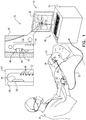
- FIG. 1 is a schematic pictorial illustration of a sinuplasty procedure using a surgical system 20, in accordance with an embodiment of the present invention.
- System 20 comprises a catheter 28, which a physician 24 inserts into a nose 26 of a patient 22 so as to remove tissue , such as a nasal polyp 45 (shown in an inset 40) at a debriding site.
- Catheter 28 comprises a proximal end 30, configured to control a distal end 38 of the catheter.
- System 20 further comprises a console 33, which comprises a processor 34, typically a general-purpose computer, with suitable front end and interface circuits for receiving signals from catheter 28, via a cable 32, and for controlling other components of system 20 described herein.
- Console 33 further comprises input devices 48 and a display 36, which are configured to display data received from processor 34 and receive inputs inserted by a user (e.g., physician 24).
- distal end 38 typically comprises a rigid hollow insertion tube 58 for insertion into the nose of patient 22.
- Tube 58 is coaxially disposed around a rotating shaft 56 (shown in greater detail in FIG. 2 ).
- Shaft 56 may be driven using any suitable mechanism, such as a direct current (DC) motor that can rotate clockwise and counterclockwise depending on the polarity of the electrical current applied to the motor.
- DC direct current
- tube 58 has an opening 44.
- Shaft 56 comprises a debriding device such as a sinuplasty cutter 46 that is aligned with opening 44 in the insertion tube.
- Cutter 46 is configured to rotate together with the shaft so as to cut polyp 45.
- inset 40 physician 24 navigates catheter 28 so that opening 44 is facing the debriding site (e.g., polyp 45).
- catheter 28 may apply suction for pulling polyp 45 therein, and cutter 46 does not block opening 44 so that polyp 45 may be inserted through opening 44 into tube 58.
- physician 24 may use console 33 or proximal end 30 to rotate shaft 56 including cutter 46 so as to remove at least part of polyp 45.
- Catheter 28 evacuates the removed polyp into a drain (not shown) located, for example, in proximal end 30. Sometimes, after being removed by cutter 46, polyp 45 may get stuck and cause clogging at any point along tube 58.
- system 20 comprises an irrigation assembly 42, mounted along an inner perimeter of tube 58. Irrigation assembly 42 is configured to irrigate the removed polyp by applying fluid 66 via one or more orifices, e.g., multiple orifices distributed along cutter 46 and tube 58 so as to evacuate the debrided polyp and prevent clogging of tube 58.
- catheter 28 may apply fluid suction, in conjunction with the irrigation, so as to improve the evacuation of fluid 66 together with the debrided polyp.
- the suction may be carried out using an internal vacuum pump (not shown) located at proximal end 30 or at console 33. Assembly 42 is further described in FIG. 2 below.
- Fig. 1 shows only elements related to the disclosed techniques, for the sake of simplicity and clarity.
- System 20 typically comprises additional modules and elements that are not directly related to the disclosed techniques, and thus, intentionally omitted from Fig. 1 and form the corresponding description.
- processor 34 may be carried out by dedicated or programmable digital hardware components.
- a sinuplasty procedure typically involves inserting catheter 28, e.g., into the patient nose, navigating it to the location of polyp 45 (or any other tissue), and removing the polyp (or other tissue) using a debriding device such as cutter 46.
- the removed polyp (or other tissue) may be large and/or have rough texture so that it may get stuck at any point along tube 58, thus clogging the tube and interrupting the sinuplasty procedure.
- FIG. 2 is a schematic side view of distal end 38, in accordance with an embodiment of the present invention.
- Distal end 38 comprises cutter 46 and irrigation assembly 42 as described above.
- Irrigation assembly 42 comprises multiple irrigation orifices 54, 54A and 54B located along assembly 42.
- Orifices 54A and 54B are located in proximity to cutter 46, and orifices 54 are grouped in a group 60 and located along distal end 38, as shown in Fig. 2 , and may continue along catheter 28 further away from cutter 46.
- Each orifice (e.g., 54A, 54B and 54) is configured to deliver pressurized fluid 66 into the internal lumen of tube 58 at a desired configurable delivery angle.
- orifices 54 are configured to deliver fluid 66 orthogonally to assembly 42 while orifices 54A and 54B are configured to deliver fluid 66 at a non-orthogonal angle.
- all the orifices may deliver fluid at a substantially similar selected angle.
- a debris 50 represents the removed portion of polyp 45, or any other tissue being evacuated.
- pressurized fluid 66 carries debris 50 (represented by arrows 52) away from cutter 46, along tube 58, toward proximal end 30.
- system 20 may apply a suction force (e.g., using a vacuum pump) in catheter 28 so as to pull debris 50 and fluid 66 toward proximal end 30.
- the suction force is typically moderate so as to prevent opening 44 from undesirably sticking to tissue because of the applied suction force.
- assembly 42 may control the delivery pressure or fluid 66 from each individual orifice.
- orifice 54A may deliver fluid 66 at a higher pressure level than orifice 54B.
- each orifice is configured to deliver fluid 66 at a predefined selected pressure.
- assembly 42 maintains sufficiently large internal pressure of fluid 66 so that all orifices, including the proximal (e.g., orifices 54) and distal orifices (e.g., 54A, 54B), deliver the fluid at a substantially uniform pressure.
- irrigation assembly 42 is laid on the inside tube 58, along the length of the tube.
- assembly 42 may have various other configurations and may be coupled to tube 58 in various other locations.
- assembly 42 may by wrapped around the inner perimeter of tube 58 so that the orifices are mounted in a cascading arrangement around the inner perimeter of insertion tube 58 rather than arranged in line as depicted in Fig. 2 . This arrangement may assist in decoupling portions of debris 50 that may undesirably adhere to specific locations along the inner perimeter of tube 58.
- the wall of tube 58 may be perforated and assembly 42 may be coupled on an outer perimeter of tube 58 so that each orifice (e.g., 54, 54A and 54B) is arranged in front of a respective hole from which it delivers fluid 66 into the internal lumen of tube 58.
- each orifice e.g., 54, 54A and 54B
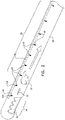
- Fig. 3 is a schematic side view of a distal end 39, in accordance with another embodiment of the present invention.
- Distal end 39 may be used, for example, to implement distal end 38 of Fig. 1 above.
- the distal end comprises tube 58 that is coaxially disposed around a rotating shaft 57, which is similar to shaft 56 of Fig. 1 above.
- shaft 57 is perforated by multiple irrigation orifices 70 that may be located at any suitable location along shaft 57.
- shaft 57 is coupled to cutter 46 so that the shaft and cutter rotate together.
- Distal end 39 is configured to apply a suction force to draw fluid 66 that enters the shaft lumen via orifices 70 in the direction of arrows 52, so as to evacuate debris 50 toward the proximal end, through the internal lumen of shaft 57.
- fluid 66 flows through a lumen that is formed between the inner surface of tube 58 and the outer surface of shaft 57, in the direction from the proximal end to distal end 39.
- Shaft 57 rotates about its longitude axis (i.e., in parallel to arrows 52) so that each of orifices 70 rotates around the inner perimeter of tube 58.
- orifice 70F rotates along a circle 72F.
- each of orifices 70 is configured to deliver fluid 66 into the internal lumen of shaft 57 during the orifice travel along its circle at any desired delivery angle relative to the rotational axis.
- the debriding device need not necessarily comprise a rotating cutter, but may alternatively comprise a scissor-shaped surgical device. Further alternatively the debriding device may comprise a cutter that travels linearly toward the distal tip so as to cut polyp 45, and retracted linearly toward the proximal end so as to allow insertion of a new object to be cut into opening 44.
- the disclosed techniques can be used, mutatis mutandis, in various other types of surgical procedures in which tissue is cut and then evacuated using a suction catheter.
- debriding may be applied to some external surface of the patient body.
- the external debriding and irrigating to the surface tissue is carried out similarly to the procedures described above but without inserting tube 58 into the patient body.
Landscapes
- Health & Medical Sciences (AREA)
- Life Sciences & Earth Sciences (AREA)
- Surgery (AREA)
- Heart & Thoracic Surgery (AREA)
- Veterinary Medicine (AREA)
- Engineering & Computer Science (AREA)
- Biomedical Technology (AREA)
- Animal Behavior & Ethology (AREA)
- General Health & Medical Sciences (AREA)
- Public Health (AREA)
- Molecular Biology (AREA)
- Nuclear Medicine, Radiotherapy & Molecular Imaging (AREA)
- Medical Informatics (AREA)
- Vascular Medicine (AREA)
- Dentistry (AREA)
- Oral & Maxillofacial Surgery (AREA)
- Otolaryngology (AREA)
- Pulmonology (AREA)
- Orthopedic Medicine & Surgery (AREA)
- Hematology (AREA)
- Anesthesiology (AREA)
- Surgical Instruments (AREA)
Applications Claiming Priority (1)
| Application Number | Priority Date | Filing Date | Title |
|---|---|---|---|
| US15/264,341 US10709472B2 (en) | 2016-09-13 | 2016-09-13 | Debrider with multiple flushing orifices |
Publications (2)
| Publication Number | Publication Date |
|---|---|
| EP3292827A1 true EP3292827A1 (de) | 2018-03-14 |
| EP3292827B1 EP3292827B1 (de) | 2021-05-26 |
Family
ID=59858894
Family Applications (1)
| Application Number | Title | Priority Date | Filing Date |
|---|---|---|---|
| EP17190526.8A Active EP3292827B1 (de) | 2016-09-13 | 2017-09-12 | Debrider mit mehreren spülungsöffnungen |
Country Status (7)
| Country | Link |
|---|---|
| US (1) | US10709472B2 (de) |
| EP (1) | EP3292827B1 (de) |
| JP (2) | JP6987576B2 (de) |
| CN (1) | CN107812264B (de) |
| AU (1) | AU2017221900A1 (de) |
| CA (1) | CA2979020A1 (de) |
| IL (2) | IL254349B (de) |
Families Citing this family (6)
| Publication number | Priority date | Publication date | Assignee | Title |
|---|---|---|---|---|
| US11185345B2 (en) * | 2018-01-31 | 2021-11-30 | Gyrus Acmi, Inc. | Debrider with external irrigation supply channel |
| CN119606285A (zh) * | 2018-02-09 | 2025-03-14 | 捷锐士阿希迈公司(以奥林巴斯美国外科技术名义) | 医疗激光设备、内窥镜控制器和医疗系统 |
| US12042163B2 (en) * | 2018-10-05 | 2024-07-23 | Acclarent, Inc. | Hollow tube surgical instrument with single axis sensor |
| US11793599B2 (en) * | 2020-08-04 | 2023-10-24 | Mazor Robotics Ltd. | Surgical cleaning tool, systems, and methods |
| KR102616368B1 (ko) * | 2021-09-17 | 2023-12-20 | 동의대학교 산학협력단 | 진단 프로브 및 이를 이용한 의료용 초음파 스캐너 |
| US12336731B2 (en) * | 2021-10-22 | 2025-06-24 | Gyrus Acmi, Inc. | High speed burr with flex shaft cooling and improved suction |
Citations (10)
| Publication number | Priority date | Publication date | Assignee | Title |
|---|---|---|---|---|
| EP0174084A2 (de) * | 1984-07-23 | 1986-03-12 | Surgical Dynamics Inc. | Chirurgisches Instrument |
| US5792167A (en) * | 1996-09-13 | 1998-08-11 | Stryker Corporation | Surgical irrigation pump and tool system |
| US6183433B1 (en) | 1995-06-30 | 2001-02-06 | Xomed Surgical Products, Inc. | Surgical suction cutting instrument with internal irrigation |
| US6293957B1 (en) | 1995-04-17 | 2001-09-25 | Medtronic Xomed, Inc. | Method of performing sinus surgery utilizing & sinus debrider instrument |
| US6371934B1 (en) | 1997-08-06 | 2002-04-16 | C. R. Bard, Inc. | Irrigation system and tip with debrider |
| WO2012058438A1 (en) * | 2010-10-28 | 2012-05-03 | Tyco Healthcare Group Lp | Material removal device and method of use |
| US20140148835A1 (en) | 2012-11-29 | 2014-05-29 | Gregory P. Schmitz | Micro debrider devices and methods of tissue removal |
| US20140148729A1 (en) | 2012-11-29 | 2014-05-29 | Gregory P. Schmitz | Micro-mechanical devices and methods for brain tumor removal |
| WO2014145052A1 (en) * | 2013-03-15 | 2014-09-18 | Health Research, Inc. | Suction device for normal and viscous materials |
| EP2913012A1 (de) * | 2014-03-01 | 2015-09-02 | Rex Medical, L.P. | Atherektomievorrichtung |
Family Cites Families (12)
| Publication number | Priority date | Publication date | Assignee | Title |
|---|---|---|---|---|
| JP2660069B2 (ja) * | 1989-11-07 | 1997-10-08 | オリンパス光学工業株式会社 | 超音波治療装置 |
| EP0926992B1 (de) * | 1996-09-17 | 2012-03-21 | Smith & Nephew, Inc. | Flexibeles chirurgisches instrument |
| US5730752A (en) * | 1996-10-29 | 1998-03-24 | Femrx, Inc. | Tubular surgical cutters having aspiration flow control ports |
| US8162966B2 (en) * | 2002-10-25 | 2012-04-24 | Hydrocision, Inc. | Surgical devices incorporating liquid jet assisted tissue manipulation and methods for their use |
| US8475487B2 (en) * | 2005-04-07 | 2013-07-02 | Medrad, Inc. | Cross stream thrombectomy catheter with flexible and expandable cage |
| US8764742B2 (en) * | 2007-04-04 | 2014-07-01 | St. Jude Medical, Atrial Fibrillation Division, Inc. | Irrigated catheter |
| US8852221B2 (en) * | 2008-06-11 | 2014-10-07 | Medtronic Ps Medical, Inc. | Surgical cutting instrument with near-perimeter interlocking coupling arrangement |
| EP2370120A4 (de) * | 2008-12-31 | 2017-10-25 | KCI Licensing, Inc. | Verteiler, systeme und verfahren zur anwendung reduzierten drucks auf eine subkutane gewebestelle |
| US8142464B2 (en) * | 2009-07-21 | 2012-03-27 | Miroslav Mitusina | Flexible inner member having a flexible region composed of longitudinally and rotationally offset partial circumferential cuts |
| US9173705B2 (en) * | 2010-05-13 | 2015-11-03 | Ncontact Surgical, Inc. | Subxyphoid epicardial ablation |
| CN203469114U (zh) * | 2013-09-05 | 2014-03-12 | 李劲松 | 处理深部感染伤口的冲洗引流装置 |
| US20160303310A1 (en) * | 2015-04-17 | 2016-10-20 | ShineIN Biotechnology Co., Ltd. | Suction-irrigation head |
-
2016
- 2016-09-13 US US15/264,341 patent/US10709472B2/en active Active
-
2017
- 2017-09-04 AU AU2017221900A patent/AU2017221900A1/en not_active Abandoned
- 2017-09-06 IL IL254349A patent/IL254349B/en active IP Right Grant
- 2017-09-12 EP EP17190526.8A patent/EP3292827B1/de active Active
- 2017-09-12 JP JP2017174937A patent/JP6987576B2/ja active Active
- 2017-09-12 CA CA2979020A patent/CA2979020A1/en not_active Abandoned
- 2017-09-13 CN CN201710822549.2A patent/CN107812264B/zh active Active
-
2020
- 2020-12-24 IL IL279773A patent/IL279773B/en unknown
-
2021
- 2021-12-01 JP JP2021195250A patent/JP7192080B2/ja active Active
Patent Citations (10)
| Publication number | Priority date | Publication date | Assignee | Title |
|---|---|---|---|---|
| EP0174084A2 (de) * | 1984-07-23 | 1986-03-12 | Surgical Dynamics Inc. | Chirurgisches Instrument |
| US6293957B1 (en) | 1995-04-17 | 2001-09-25 | Medtronic Xomed, Inc. | Method of performing sinus surgery utilizing & sinus debrider instrument |
| US6183433B1 (en) | 1995-06-30 | 2001-02-06 | Xomed Surgical Products, Inc. | Surgical suction cutting instrument with internal irrigation |
| US5792167A (en) * | 1996-09-13 | 1998-08-11 | Stryker Corporation | Surgical irrigation pump and tool system |
| US6371934B1 (en) | 1997-08-06 | 2002-04-16 | C. R. Bard, Inc. | Irrigation system and tip with debrider |
| WO2012058438A1 (en) * | 2010-10-28 | 2012-05-03 | Tyco Healthcare Group Lp | Material removal device and method of use |
| US20140148835A1 (en) | 2012-11-29 | 2014-05-29 | Gregory P. Schmitz | Micro debrider devices and methods of tissue removal |
| US20140148729A1 (en) | 2012-11-29 | 2014-05-29 | Gregory P. Schmitz | Micro-mechanical devices and methods for brain tumor removal |
| WO2014145052A1 (en) * | 2013-03-15 | 2014-09-18 | Health Research, Inc. | Suction device for normal and viscous materials |
| EP2913012A1 (de) * | 2014-03-01 | 2015-09-02 | Rex Medical, L.P. | Atherektomievorrichtung |
Also Published As
| Publication number | Publication date |
|---|---|
| IL254349A0 (en) | 2017-11-30 |
| JP2022019879A (ja) | 2022-01-27 |
| AU2017221900A1 (en) | 2018-03-29 |
| JP2018043008A (ja) | 2018-03-22 |
| IL279773B (en) | 2022-02-01 |
| CN107812264A (zh) | 2018-03-20 |
| JP6987576B2 (ja) | 2022-01-05 |
| IL279773A (en) | 2021-01-31 |
| IL254349B (en) | 2021-01-31 |
| US20180070981A1 (en) | 2018-03-15 |
| EP3292827B1 (de) | 2021-05-26 |
| CA2979020A1 (en) | 2018-03-13 |
| JP7192080B2 (ja) | 2022-12-19 |
| US10709472B2 (en) | 2020-07-14 |
| CN107812264B (zh) | 2022-04-15 |
Similar Documents
| Publication | Publication Date | Title |
|---|---|---|
| EP3292827B1 (de) | Debrider mit mehreren spülungsöffnungen | |
| US10463432B2 (en) | Tissue and stone removal device and related methods of use | |
| US20250152240A1 (en) | Medical device and methods of use | |
| EP3897767B1 (de) | Flexibles ureteroskop mit debrisabsaugung | |
| US11389183B2 (en) | Ultrasonic surgical probe, assembly, and related method | |
| US9108027B2 (en) | Interventional catheter housing assemblies incorporating guide wire brakes and management systems | |
| CA3169535A1 (en) | Suction and irrigation control system and method | |
| EP3345557B1 (de) | Kombinierter debrider und koagulator | |
| EP3524186B1 (de) | Debrider mit externer spülversorgung | |
| WO2021173775A1 (en) | Endoscope unclogging system and method | |
| HK40006052B (en) | Ultrasonic surgical probe, assembly, and related method | |
| HK40006052A (en) | Ultrasonic surgical probe, assembly, and related method |
Legal Events
| Date | Code | Title | Description |
|---|---|---|---|
| PUAI | Public reference made under article 153(3) epc to a published international application that has entered the european phase |
Free format text: ORIGINAL CODE: 0009012 |
|
| STAA | Information on the status of an ep patent application or granted ep patent |
Free format text: STATUS: THE APPLICATION HAS BEEN PUBLISHED |
|
| AK | Designated contracting states |
Kind code of ref document: A1 Designated state(s): AL AT BE BG CH CY CZ DE DK EE ES FI FR GB GR HR HU IE IS IT LI LT LU LV MC MK MT NL NO PL PT RO RS SE SI SK SM TR |
|
| AX | Request for extension of the european patent |
Extension state: BA ME |
|
| STAA | Information on the status of an ep patent application or granted ep patent |
Free format text: STATUS: REQUEST FOR EXAMINATION WAS MADE |
|
| 17P | Request for examination filed |
Effective date: 20180829 |
|
| RBV | Designated contracting states (corrected) |
Designated state(s): AL AT BE BG CH CY CZ DE DK EE ES FI FR GB GR HR HU IE IS IT LI LT LU LV MC MK MT NL NO PL PT RO RS SE SI SK SM TR |
|
| STAA | Information on the status of an ep patent application or granted ep patent |
Free format text: STATUS: EXAMINATION IS IN PROGRESS |
|
| 17Q | First examination report despatched |
Effective date: 20191120 |
|
| RIC1 | Information provided on ipc code assigned before grant |
Ipc: A61B 17/24 20060101ALI20201125BHEP Ipc: A61B 17/32 20060101AFI20201125BHEP Ipc: A61B 17/3207 20060101ALN20201125BHEP |
|
| RIC1 | Information provided on ipc code assigned before grant |
Ipc: A61B 17/32 20060101AFI20201207BHEP Ipc: A61B 17/24 20060101ALI20201207BHEP Ipc: A61B 17/3207 20060101ALN20201207BHEP |
|
| GRAP | Despatch of communication of intention to grant a patent |
Free format text: ORIGINAL CODE: EPIDOSNIGR1 |
|
| STAA | Information on the status of an ep patent application or granted ep patent |
Free format text: STATUS: GRANT OF PATENT IS INTENDED |
|
| INTG | Intention to grant announced |
Effective date: 20210121 |
|
| GRAS | Grant fee paid |
Free format text: ORIGINAL CODE: EPIDOSNIGR3 |
|
| GRAA | (expected) grant |
Free format text: ORIGINAL CODE: 0009210 |
|
| STAA | Information on the status of an ep patent application or granted ep patent |
Free format text: STATUS: THE PATENT HAS BEEN GRANTED |
|
| RAP3 | Party data changed (applicant data changed or rights of an application transferred) |
Owner name: BIOSENSE WEBSTER (ISRAEL) LTD. |
|
| AK | Designated contracting states |
Kind code of ref document: B1 Designated state(s): AL AT BE BG CH CY CZ DE DK EE ES FI FR GB GR HR HU IE IS IT LI LT LU LV MC MK MT NL NO PL PT RO RS SE SI SK SM TR |
|
| REG | Reference to a national code |
Ref country code: GB Ref legal event code: FG4D |
|
| REG | Reference to a national code |
Ref country code: CH Ref legal event code: EP |
|
| REG | Reference to a national code |
Ref country code: AT Ref legal event code: REF Ref document number: 1395416 Country of ref document: AT Kind code of ref document: T Effective date: 20210615 |
|
| REG | Reference to a national code |
Ref country code: DE Ref legal event code: R096 Ref document number: 602017039165 Country of ref document: DE |
|
| REG | Reference to a national code |
Ref country code: IE Ref legal event code: FG4D |
|
| REG | Reference to a national code |
Ref country code: NL Ref legal event code: FP |
|
| REG | Reference to a national code |
Ref country code: LT Ref legal event code: MG9D |
|
| REG | Reference to a national code |
Ref country code: AT Ref legal event code: MK05 Ref document number: 1395416 Country of ref document: AT Kind code of ref document: T Effective date: 20210526 |
|
| PG25 | Lapsed in a contracting state [announced via postgrant information from national office to epo] |
Ref country code: FI Free format text: LAPSE BECAUSE OF FAILURE TO SUBMIT A TRANSLATION OF THE DESCRIPTION OR TO PAY THE FEE WITHIN THE PRESCRIBED TIME-LIMIT Effective date: 20210526 Ref country code: LT Free format text: LAPSE BECAUSE OF FAILURE TO SUBMIT A TRANSLATION OF THE DESCRIPTION OR TO PAY THE FEE WITHIN THE PRESCRIBED TIME-LIMIT Effective date: 20210526 Ref country code: HR Free format text: LAPSE BECAUSE OF FAILURE TO SUBMIT A TRANSLATION OF THE DESCRIPTION OR TO PAY THE FEE WITHIN THE PRESCRIBED TIME-LIMIT Effective date: 20210526 Ref country code: AT Free format text: LAPSE BECAUSE OF FAILURE TO SUBMIT A TRANSLATION OF THE DESCRIPTION OR TO PAY THE FEE WITHIN THE PRESCRIBED TIME-LIMIT Effective date: 20210526 Ref country code: BG Free format text: LAPSE BECAUSE OF FAILURE TO SUBMIT A TRANSLATION OF THE DESCRIPTION OR TO PAY THE FEE WITHIN THE PRESCRIBED TIME-LIMIT Effective date: 20210826 |
|
| PG25 | Lapsed in a contracting state [announced via postgrant information from national office to epo] |
Ref country code: RS Free format text: LAPSE BECAUSE OF FAILURE TO SUBMIT A TRANSLATION OF THE DESCRIPTION OR TO PAY THE FEE WITHIN THE PRESCRIBED TIME-LIMIT Effective date: 20210526 Ref country code: SE Free format text: LAPSE BECAUSE OF FAILURE TO SUBMIT A TRANSLATION OF THE DESCRIPTION OR TO PAY THE FEE WITHIN THE PRESCRIBED TIME-LIMIT Effective date: 20210526 Ref country code: PL Free format text: LAPSE BECAUSE OF FAILURE TO SUBMIT A TRANSLATION OF THE DESCRIPTION OR TO PAY THE FEE WITHIN THE PRESCRIBED TIME-LIMIT Effective date: 20210526 Ref country code: PT Free format text: LAPSE BECAUSE OF FAILURE TO SUBMIT A TRANSLATION OF THE DESCRIPTION OR TO PAY THE FEE WITHIN THE PRESCRIBED TIME-LIMIT Effective date: 20210927 Ref country code: NO Free format text: LAPSE BECAUSE OF FAILURE TO SUBMIT A TRANSLATION OF THE DESCRIPTION OR TO PAY THE FEE WITHIN THE PRESCRIBED TIME-LIMIT Effective date: 20210826 Ref country code: IS Free format text: LAPSE BECAUSE OF FAILURE TO SUBMIT A TRANSLATION OF THE DESCRIPTION OR TO PAY THE FEE WITHIN THE PRESCRIBED TIME-LIMIT Effective date: 20210926 Ref country code: GR Free format text: LAPSE BECAUSE OF FAILURE TO SUBMIT A TRANSLATION OF THE DESCRIPTION OR TO PAY THE FEE WITHIN THE PRESCRIBED TIME-LIMIT Effective date: 20210827 Ref country code: LV Free format text: LAPSE BECAUSE OF FAILURE TO SUBMIT A TRANSLATION OF THE DESCRIPTION OR TO PAY THE FEE WITHIN THE PRESCRIBED TIME-LIMIT Effective date: 20210526 |
|
| PG25 | Lapsed in a contracting state [announced via postgrant information from national office to epo] |
Ref country code: ES Free format text: LAPSE BECAUSE OF FAILURE TO SUBMIT A TRANSLATION OF THE DESCRIPTION OR TO PAY THE FEE WITHIN THE PRESCRIBED TIME-LIMIT Effective date: 20210526 Ref country code: RO Free format text: LAPSE BECAUSE OF FAILURE TO SUBMIT A TRANSLATION OF THE DESCRIPTION OR TO PAY THE FEE WITHIN THE PRESCRIBED TIME-LIMIT Effective date: 20210526 Ref country code: CZ Free format text: LAPSE BECAUSE OF FAILURE TO SUBMIT A TRANSLATION OF THE DESCRIPTION OR TO PAY THE FEE WITHIN THE PRESCRIBED TIME-LIMIT Effective date: 20210526 Ref country code: DK Free format text: LAPSE BECAUSE OF FAILURE TO SUBMIT A TRANSLATION OF THE DESCRIPTION OR TO PAY THE FEE WITHIN THE PRESCRIBED TIME-LIMIT Effective date: 20210526 Ref country code: EE Free format text: LAPSE BECAUSE OF FAILURE TO SUBMIT A TRANSLATION OF THE DESCRIPTION OR TO PAY THE FEE WITHIN THE PRESCRIBED TIME-LIMIT Effective date: 20210526 Ref country code: SK Free format text: LAPSE BECAUSE OF FAILURE TO SUBMIT A TRANSLATION OF THE DESCRIPTION OR TO PAY THE FEE WITHIN THE PRESCRIBED TIME-LIMIT Effective date: 20210526 Ref country code: SM Free format text: LAPSE BECAUSE OF FAILURE TO SUBMIT A TRANSLATION OF THE DESCRIPTION OR TO PAY THE FEE WITHIN THE PRESCRIBED TIME-LIMIT Effective date: 20210526 |
|
| REG | Reference to a national code |
Ref country code: DE Ref legal event code: R097 Ref document number: 602017039165 Country of ref document: DE |
|
| PLBE | No opposition filed within time limit |
Free format text: ORIGINAL CODE: 0009261 |
|
| STAA | Information on the status of an ep patent application or granted ep patent |
Free format text: STATUS: NO OPPOSITION FILED WITHIN TIME LIMIT |
|
| REG | Reference to a national code |
Ref country code: CH Ref legal event code: PL |
|
| 26N | No opposition filed |
Effective date: 20220301 |
|
| REG | Reference to a national code |
Ref country code: BE Ref legal event code: MM Effective date: 20210930 |
|
| PG25 | Lapsed in a contracting state [announced via postgrant information from national office to epo] |
Ref country code: IS Free format text: LAPSE BECAUSE OF FAILURE TO SUBMIT A TRANSLATION OF THE DESCRIPTION OR TO PAY THE FEE WITHIN THE PRESCRIBED TIME-LIMIT Effective date: 20210926 Ref country code: MC Free format text: LAPSE BECAUSE OF FAILURE TO SUBMIT A TRANSLATION OF THE DESCRIPTION OR TO PAY THE FEE WITHIN THE PRESCRIBED TIME-LIMIT Effective date: 20210526 Ref country code: AL Free format text: LAPSE BECAUSE OF FAILURE TO SUBMIT A TRANSLATION OF THE DESCRIPTION OR TO PAY THE FEE WITHIN THE PRESCRIBED TIME-LIMIT Effective date: 20210526 |
|
| PG25 | Lapsed in a contracting state [announced via postgrant information from national office to epo] |
Ref country code: LU Free format text: LAPSE BECAUSE OF NON-PAYMENT OF DUE FEES Effective date: 20210912 Ref country code: IE Free format text: LAPSE BECAUSE OF NON-PAYMENT OF DUE FEES Effective date: 20210912 Ref country code: BE Free format text: LAPSE BECAUSE OF NON-PAYMENT OF DUE FEES Effective date: 20210930 |
|
| PG25 | Lapsed in a contracting state [announced via postgrant information from national office to epo] |
Ref country code: LI Free format text: LAPSE BECAUSE OF NON-PAYMENT OF DUE FEES Effective date: 20210930 Ref country code: CH Free format text: LAPSE BECAUSE OF NON-PAYMENT OF DUE FEES Effective date: 20210930 |
|
| PGFP | Annual fee paid to national office [announced via postgrant information from national office to epo] |
Ref country code: NL Payment date: 20220819 Year of fee payment: 6 |
|
| PG25 | Lapsed in a contracting state [announced via postgrant information from national office to epo] |
Ref country code: HU Free format text: LAPSE BECAUSE OF FAILURE TO SUBMIT A TRANSLATION OF THE DESCRIPTION OR TO PAY THE FEE WITHIN THE PRESCRIBED TIME-LIMIT; INVALID AB INITIO Effective date: 20170912 |
|
| PG25 | Lapsed in a contracting state [announced via postgrant information from national office to epo] |
Ref country code: CY Free format text: LAPSE BECAUSE OF FAILURE TO SUBMIT A TRANSLATION OF THE DESCRIPTION OR TO PAY THE FEE WITHIN THE PRESCRIBED TIME-LIMIT Effective date: 20210526 |
|
| PG25 | Lapsed in a contracting state [announced via postgrant information from national office to epo] |
Ref country code: MK Free format text: LAPSE BECAUSE OF FAILURE TO SUBMIT A TRANSLATION OF THE DESCRIPTION OR TO PAY THE FEE WITHIN THE PRESCRIBED TIME-LIMIT Effective date: 20210526 |
|
| REG | Reference to a national code |
Ref country code: NL Ref legal event code: MM Effective date: 20231001 |
|
| PG25 | Lapsed in a contracting state [announced via postgrant information from national office to epo] |
Ref country code: NL Free format text: LAPSE BECAUSE OF NON-PAYMENT OF DUE FEES Effective date: 20231001 |
|
| PG25 | Lapsed in a contracting state [announced via postgrant information from national office to epo] |
Ref country code: NL Free format text: LAPSE BECAUSE OF NON-PAYMENT OF DUE FEES Effective date: 20231001 |
|
| PG25 | Lapsed in a contracting state [announced via postgrant information from national office to epo] |
Ref country code: MT Free format text: LAPSE BECAUSE OF FAILURE TO SUBMIT A TRANSLATION OF THE DESCRIPTION OR TO PAY THE FEE WITHIN THE PRESCRIBED TIME-LIMIT Effective date: 20210526 |
|
| PGFP | Annual fee paid to national office [announced via postgrant information from national office to epo] |
Ref country code: DE Payment date: 20250730 Year of fee payment: 9 |
|
| PGFP | Annual fee paid to national office [announced via postgrant information from national office to epo] |
Ref country code: IT Payment date: 20250825 Year of fee payment: 9 |
|
| PGFP | Annual fee paid to national office [announced via postgrant information from national office to epo] |
Ref country code: GB Payment date: 20250731 Year of fee payment: 9 |
|
| PGFP | Annual fee paid to national office [announced via postgrant information from national office to epo] |
Ref country code: FR Payment date: 20250808 Year of fee payment: 9 |
|
| PG25 | Lapsed in a contracting state [announced via postgrant information from national office to epo] |
Ref country code: TR Free format text: LAPSE BECAUSE OF FAILURE TO SUBMIT A TRANSLATION OF THE DESCRIPTION OR TO PAY THE FEE WITHIN THE PRESCRIBED TIME-LIMIT Effective date: 20210526 |