EP2913151A1 - Outil de finissage de surface - Google Patents
Outil de finissage de surface Download PDFInfo
- Publication number
- EP2913151A1 EP2913151A1 EP15000037.0A EP15000037A EP2913151A1 EP 2913151 A1 EP2913151 A1 EP 2913151A1 EP 15000037 A EP15000037 A EP 15000037A EP 2913151 A1 EP2913151 A1 EP 2913151A1
- Authority
- EP
- European Patent Office
- Prior art keywords
- working medium
- medium carrier
- tool according
- grooves
- cover
- Prior art date
- Legal status (The legal status is an assumption and is not a legal conclusion. Google has not performed a legal analysis and makes no representation as to the accuracy of the status listed.)
- Granted
Links
- 241000446313 Lamella Species 0.000 claims abstract description 6
- 238000000227 grinding Methods 0.000 claims abstract description 6
- 239000004033 plastic Substances 0.000 claims abstract description 6
- 238000005498 polishing Methods 0.000 claims abstract description 6
- 238000004140 cleaning Methods 0.000 claims abstract description 3
- 150000001875 compounds Chemical class 0.000 claims 1
- 230000007717 exclusion Effects 0.000 claims 1
- 238000004519 manufacturing process Methods 0.000 abstract description 10
- 238000001746 injection moulding Methods 0.000 description 5
- 230000015572 biosynthetic process Effects 0.000 description 4
- 238000005755 formation reaction Methods 0.000 description 4
- 239000000463 material Substances 0.000 description 4
- 238000004026 adhesive bonding Methods 0.000 description 3
- 239000000428 dust Substances 0.000 description 3
- 238000000605 extraction Methods 0.000 description 3
- 239000012530 fluid Substances 0.000 description 3
- 230000006978 adaptation Effects 0.000 description 2
- 230000000295 complement effect Effects 0.000 description 2
- 230000008878 coupling Effects 0.000 description 2
- 238000010168 coupling process Methods 0.000 description 2
- 238000005859 coupling reaction Methods 0.000 description 2
- 230000002093 peripheral effect Effects 0.000 description 2
- 238000003860 storage Methods 0.000 description 2
- 230000003313 weakening effect Effects 0.000 description 2
- 238000003466 welding Methods 0.000 description 2
- 238000005299 abrasion Methods 0.000 description 1
- 230000001174 ascending effect Effects 0.000 description 1
- 238000005452 bending Methods 0.000 description 1
- 238000006243 chemical reaction Methods 0.000 description 1
- 238000006073 displacement reaction Methods 0.000 description 1
- 230000000694 effects Effects 0.000 description 1
- 238000005516 engineering process Methods 0.000 description 1
- 244000144992 flock Species 0.000 description 1
- 238000002347 injection Methods 0.000 description 1
- 239000007924 injection Substances 0.000 description 1
- 238000009434 installation Methods 0.000 description 1
- 230000013011 mating Effects 0.000 description 1
- 239000002184 metal Substances 0.000 description 1
- 238000002156 mixing Methods 0.000 description 1
- 239000012815 thermoplastic material Substances 0.000 description 1
- 210000000707 wrist Anatomy 0.000 description 1
Images




Classifications
-
- B—PERFORMING OPERATIONS; TRANSPORTING
- B24—GRINDING; POLISHING
- B24D—TOOLS FOR GRINDING, BUFFING OR SHARPENING
- B24D9/00—Wheels or drums supporting in exchangeable arrangement a layer of flexible abrasive material, e.g. sandpaper
- B24D9/08—Circular back-plates for carrying flexible material
-
- B—PERFORMING OPERATIONS; TRANSPORTING
- B24—GRINDING; POLISHING
- B24D—TOOLS FOR GRINDING, BUFFING OR SHARPENING
- B24D13/00—Wheels having flexibly-acting working parts, e.g. buffing wheels; Mountings therefor
- B24D13/14—Wheels having flexibly-acting working parts, e.g. buffing wheels; Mountings therefor acting by the front face
- B24D13/142—Wheels of special form
-
- B—PERFORMING OPERATIONS; TRANSPORTING
- B24—GRINDING; POLISHING
- B24D—TOOLS FOR GRINDING, BUFFING OR SHARPENING
- B24D13/00—Wheels having flexibly-acting working parts, e.g. buffing wheels; Mountings therefor
- B24D13/14—Wheels having flexibly-acting working parts, e.g. buffing wheels; Mountings therefor acting by the front face
- B24D13/16—Wheels having flexibly-acting working parts, e.g. buffing wheels; Mountings therefor acting by the front face comprising pleated flaps or strips
-
- B—PERFORMING OPERATIONS; TRANSPORTING
- B24—GRINDING; POLISHING
- B24D—TOOLS FOR GRINDING, BUFFING OR SHARPENING
- B24D13/00—Wheels having flexibly-acting working parts, e.g. buffing wheels; Mountings therefor
- B24D13/20—Mountings for the wheels
-
- B—PERFORMING OPERATIONS; TRANSPORTING
- B24—GRINDING; POLISHING
- B24D—TOOLS FOR GRINDING, BUFFING OR SHARPENING
- B24D15/00—Hand tools or other devices for non-rotary grinding, polishing, or stropping
-
- B—PERFORMING OPERATIONS; TRANSPORTING
- B24—GRINDING; POLISHING
- B24D—TOOLS FOR GRINDING, BUFFING OR SHARPENING
- B24D15/00—Hand tools or other devices for non-rotary grinding, polishing, or stropping
- B24D15/02—Hand tools or other devices for non-rotary grinding, polishing, or stropping rigid; with rigidly-supported operative surface
- B24D15/023—Hand tools or other devices for non-rotary grinding, polishing, or stropping rigid; with rigidly-supported operative surface using in exchangeable arrangement a layer of flexible material
Definitions
- the invention relates to a tool for surface finishing in the form of a grinding plate, polishing plate o. The like., Which has a fitted with lamella underside and with this underside flat to create a workpiece and use with flat working movements.
- Such tools can be designed both for manual operation, as well as - with mating drive connections - for mechanical operation, wherein the machine operation in most cases a rotation about an underside of the tool substantially vertical axis, more rarely an eccentric or oscillating translational Movement provides.
- the use of fins as a working means allows the provision of a significantly larger amount of working fluid compared to abrasive sheets and the like. Working tools and thus longer life of the tool and provides the effective lamella width below the bottom of a volume ready to store in the worn or worn material and that even in the surface finishing of wavy or curved surfaces allows an adjustment.
- Tools of the type considered here are, for example, from WO 2012/163357 A1 or the EP 1 633 530 A known in which slats used in grooves on the underside of a top-closed working medium carrier and, for example are fixed by gluing or pouring.
- a manufacturing method of this type is not very suitable for mass production and requires a variety of different manufacturing and assembly steps.
- the object of the invention is in contrast to provide a tool that is cheap to produce as a standard product and easy to assemble with lamellas for various requirements and that also allows the user side a conversion or renewal with replacement worn lamellae.
- this object is achieved with a tool according to claim 1.
- the working medium carrier consists of a one-piece plastic injection-molded part, which holds the lamellae in grooves, which open towards the bottom narrows
- a constructive key component for the entire tool is created.
- the upwardly unobstructed open grooves allow designs of the injection molding tool with simple designs and easy opening, to make the injection molding and in particular the demolding quickly and safely. Nevertheless, the slats in the grooves are already held on several sides.
- the lid closes the grooves on the top side, holds the lamella captive in the grooves and also covers the top of the tool carrier, so that with rotating or oscillating tool protection against contact is given, the surface can be made appealing and less susceptible to dirt and handles such as hand-operated tools Form on the lid and form are.
- the lid with the working medium carrier cooperatively designed so that it picks up with its underside on the lamellae or their retaining edge and fixed or clamped the lamellae in the groove and in particular against longitudinal displacements in the frictionally or positively fixed.
- a lid is suitable to form ducts for air guidance of suction air with the working medium carrier, which open approximately between the slats on the underside and lead out with connection openings in the top of the lid - approximately matching exhaust ports in standard versions of drive machines.
- the lid which itself may also consist of several parts and approximately in a rotating tool of one or more ring elements, must be regularly connected for work use of the tool firmly with working medium carrier. This does not exclude a detachable connection of the lid or part of this relative to the working medium carrier and also requires neither a considerable manufacturing effort in the production nor a complicated structure of the tool.
- the connection between the lid and working medium carrier can be done by simple screwing or brackets, as well as locking can be provided.
- connection pairs can already be formed during injection molding and engaged with a simple rotation
- the direction of rotation preferably corresponds to the workload to preclude disengagement at workload
- a detachable connection can give the user of the tool the possibility of slats in whole or in part to replace wear or adaptation to the work.
- the lid can be simply and robustly connected to the working medium carrier to form a "disposable tool", such as by gluing or - in the case of matching thermoplastic materials of injection-molded materials in the lid and working medium carrier - welding.
- a "disposable tool” such as by gluing or - in the case of matching thermoplastic materials of injection-molded materials in the lid and working medium carrier - welding.
- the design of the tool according to the invention allows a variable assembly in the production with advantages for simple operations in mass production.
- a drive connection suitable for the drive is to be provided, which is expediently fixedly connected to the working medium carrier itself and thus enables a robust and direct guidance of the drive forces, while the cover remains stress-free and, accordingly, can be carried out easily.
- a lid in the form of a cap closed on the top can be provided with a grip area, the handle being able to be grasped in the manner of a knob, or even with a flat imprint and tangible in a wrist strap.
- FIG. 1 A total of 1 designated tool for surface finishing such as cleaning, grinding or polishing by means of underside projecting and provided with suitable working fluid slats 2 is rotationally symmetrical with respect to a vertical center axis formed with a working medium carrier 3 and a lid 4, both firm and sufficiently reliable over thread formations too are connect, wherein a thread forming 5 in a central opening 6 of the lid 4 on matching male threaded portions on the opening 6 by a cross-shaped drive connection (not shown) engages, which is integrally connected to the working medium carrier 3 and projects in the middle of this upwards.
- a cross-shaped drive connection (not shown) engages, which is integrally connected to the working medium carrier 3 and projects in the middle of this upwards.
- Similar designs of such a drive are described below with reference to Fig. 16 and 18 illustrated.
- the thread formations as the thread 5 in Fig. 1 are only one example of many practical connection possibilities between the lid and working medium carrier, which may for example also be formed like a bayonet, but could also be provided on the periphery of the working medium carrier 3 and the lid 4.
- connection between the cover 4 and the working medium carrier 3 by screwing, which are provided for example on a screwing circle, or brackets, possibly also by profiling or meshing between cover 4 and working medium carrier. 3 could be relieved against rotation to provide a releasable connection.
- a solubility of the lid from the working medium carrier is not interested in or after use, both can be permanently connected to each other during assembly, for example by gluing or welding.
- the working medium carrier 3 has for receiving lamellae 2 predominantly radially aligned grooves 7, the groove cross section is designed for the cross section of an upper thickened retaining edge 8 of the slats 2, facing away from the retaining edge and thereby pass through a constriction 9 of the groove cross-section before they emerge functionally effective on an underside 10 of the working medium carrier 3 with an exposed strip.
- the grooves 7 open at the edge with open groove cross-section and thus allow placement of the working medium carrier 3 with the strip-shaped, stiffened by the thickened retaining edge 8 slats 2 by these are inserted from outside to inside in the longitudinal direction in the grooves 7.
- the grooves 7 are - due to manufacturing technology - formed unobstructed upwards open. This makes it possible in particular to refrain from complicated multipart injection molds for a working medium carrier 3 with narrowed and accessible grooves and instead a simple, preferably only two-part mold pretending to be fast, easy and robust to handle also for demolding in a simple opening movement.
- top and end-side opening grooves 7 gaps are formed, between which the working medium carrier 3 keeps sectors that are interconnected only in a central region.
- the grooves are indeed, how Fig. 1 indicated by the lower edges of the slats 2, different lengths, namely alternately shorter or longer to cover the bottom 10 of the working medium carrier more uniformly with the flock of slats 2, nevertheless, results from the grooves 7, a mechanical weakening of the working medium carrier 3.
- This weakening could Although basically still be reduced via a (not shown) connecting ring on the outer edge, which extends above the open end sections of the grooves 7 as well as outside the upper-side openings of the grooves. In the present case, however, a stiffening using the cover 4 is achieved.
- a collar 12 is circumferentially formed in addition to a substantially flat top plate 11, which then after the working medium carrier 3 equipped with slats 2 and connected to the lid 4, a peripheral edge 13 of the working medium carrier 3 tightly encloses.
- the open end sections of the grooves 7 are sealed off against ejection of the slats 2.
- annular collar 12 is equipped with internally formed locking knobs 14, which engage in the end cross sections of the grooves 7 and the sectors of the working medium carrier 3 against each other, but at the same time also represent a Rasthemmung in the circumferential direction against a loosening or loosening movement in the connection between the working medium carrier 3 and cover 4, when about during use of the tool torque loads occur.
- the direction of rotation in the thread formations 5 between the cover 4 and the working medium carrier 3 is selected so that the loading moments act in the sense of a firm connection.
- the annular collar 12 also has a total or at least partially encircling locking rim 15, with which the annular collar 12 can also engage below the working medium carrier 3 on the underside, in order to secure the connection between the lid 4 and the working medium carrier 3.
- the lid 4 has, in addition to the central recess 6, a ring of evenly distributed openings in the circle, which serve as connection openings 16 for a dust extraction. These are, for example, suitable for a concentric suction air connection of a drive with the outside diameter.
- the connection openings 16 and the farther outward suction still so far that a direct suction air is given.
- the lid 4 Thus, if such a tool is to be equipped for use with a dust extraction, then in a simple manner to set up the suction openings 17 and place the top-side connection openings in the cover suitable for the machine-side conclusion.
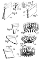
- Fig. 2 to 11 Examples are shown in which the lamellae, which allow not only compared to grinding or polishing papers or the like surface work equipment to provide larger amounts of working fluid and also provide intermediate volume for abrasion and dirt, are also different.
- a tool of the type presented here is suitable to be equipped with different slats, although a vote of the upper retaining edge is to specify the grooves 7 of the working medium carrier.
- a simple embodiment of a blade 19 according to Fig. 2 provides that three strips of double width, centrally folded longitudinally around an inner cable 20 are placed with a round cross-section and fixed in this position.
- the slats provide a longitudinally insertable strip mold according to the invention with thickened retaining edge.
- a variant of a blade 21 according to 4 and 5 has a relatively thin inner cable 22, but is reinforced in the region of the reinforced retaining edge on the periphery with a piping 23 to achieve an easily retractable, but nevertheless low-play in the groove 7 of the tool carrier 3 to be arranged form the retaining edge.
- FIGS. 6, 7 and 8 different lamellae 24, 25, 26 are shown, whose lower edge is not simply formed parallel to the retaining edge, but contoured in a special way, for example, a concave envelope surface 27 in the assembled state according to Fig. 9 or a convex envelope surface 28 according to FIG Fig. 10 or a wavy lower surface 29 according to Fig. 11 to achieve.
- a concave envelope surface 27 in the assembled state according to Fig. 9 or a convex envelope surface 28 according to FIG Fig. 10 or a wavy lower surface 29 according to Fig. 11 to achieve.
- embodiments for specific applications such as hollow or spherical shapes to capture specifically.
- One opposite the tool 1 to Fig. 1 modified embodiment of a tool 31 results from the Fig. 12 to 15 , The description of the tool 1 can be referred to.
- the lid 33 is not integrally provided with an annular collar but is gripped and clamped together with the working medium carrier 32 by a peripheral ring 36.
- a solubility of the retaining ring 36 can be achieved in that this radially inwardly directed coupling pins 37 (FIG. Fig. 15 ), which in circumferential grooves 38 in the lid 33 and in the working medium carrier 32 (FIG. FIGS. 13 and 14 ) movably engage to achieve a retaining connection, wherein the grooves guided in the manner of a bayonet connection and thus the connection are secured against easy release.
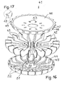
- FIGS. 16 and 17 Another tool 41 after FIGS. 16 and 17 has to a lower surface from which open the lamellae over narrowed groove cross-sections, a highly curved edge region on which the arc-shaped Haltr skilledn 43 suitably shaped lamellar strips 42 also emerge radially.
- Grooves 44 in one of the lower surface having work support means 45 are not straight, but formed on the outside ascending.
- a cover 46 has a convex, the holder edges 43 of the fins 42 of the cupped bottom 47 with open Nutausformungen 48 for top fixing the holder edges 43 of the fins 42nd
- Outwardly projecting latching formations 49 engage in the end open groove cross-sections 44 of the working medium carrier 45 so as to one to stabilize the working medium carrier 45 and to set the cover 46 against rotation of the working medium carrier 45.
- the connection between the cover 46 and working medium carrier 45 in the axial direction is in Fig. 16 not illustrated. This can, as stated above, be achieved in various ways by common means.
- a conventional drive connection 50 is shown in a pin shape, in which the injection molding process, a metal form nut 51 is embedded because of the greater strength.
- This drive port 50 passes through the lid 46 in a central opening, so that the power flow from Drive over a short distance can go directly into the working medium carrier 45 while the lid remains unloaded.
- the working medium carrier 45 has suction slots 52 which open on the underside between the fins 42 and the upper side with SauganBankschlitzen 53 in the lid 46 in conjunction to create an air duct for dust extraction, the slots 52 and 53 by no means must be congruent. Typically, the slots 52 extend radially farther outward than the slots 53 radially defined for the corresponding machine port.
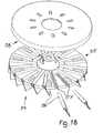
- FIG. 18 shows a tool 54 according to the invention, in which in a working medium carrier 55 of the otherwise previously described type slats 56 are not issued vertically downwards but obliquely.
- an inclination of the slats against the direction of rotation may also be considered, for example, to allow the slats build a bending stress during polishing or grinding and thus to achieve a cushioning effect.
- the respective desired inclination of grooves 57 can be predetermined and stabilized by picking up a cover 58.
- the work support means 55 is provided with an integrally molded drive connection 59, so that the forces applied by the respective drive or moments within the working medium carrier 55 are transferred to the fins 56, while the cover 58 is so far outside the power flow.
- FIGS. 19 and 20 is a tool 60 for surface finishing by hand, wherein Fig. 20 only shows the exploded view or single part view before the finished installation of the tool.
- the tool 60 has a working medium carrier 61 in a rotationally symmetrical shape with radial grooves 62 for receiving fins 63, but is not provided in the middle with a drive connection for mechanical operation, but with a coupling ring 64, on which a hand knob 65, by a Central opening 66 of a lid 67 with a locking pin 68 inserted and latched.
- the design of the working medium carrier 61 and the lid 67, as well as their adaptation to each other follows the above-described designs for a machine-operated tool. Again, the force is introduced from the hand knob 65 directly into the working medium carrier 61, bypassing the lid 67, which is interpreted on the cover of the working medium carrier 61 and the determination of the fins 63 in the grooves 62.
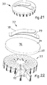
- FIG. 21 Another hand operated tool 70 is seen obliquely from above in FIG Fig. 21 and in an exploded view in FIG Fig. 22 can be seen, wherein the design of a rotationally symmetrical working medium carrier 71 with grooves 72 for storage of fins 73 corresponds to the above-described design lines, but has no central introduction of force.
- the working medium carrier 71 is rather firmly connected to a cover 74, which not only the cover of the working medium carrier 71 and the positional fixing of the slats 73 in this with its (not shown) underside and an outer cross-annular collar 75 accepts, but also with a convex top side 76 provides a handle area for manual operation.
- a hand strap 77 is provided on the upper side, which can be welded or sealed, for example, of plastic material, if the lid 74 is made of a suitable plastic material, otherwise screwed or riveted, for example, wherein the hand strap 77 in terms of width adjustment of two strips 78, 79 is to be fixed with spaced ends on the lid 74 and to be fixed to overlapping areas by a hook and loop fastener or other releasable connection.
- lid 81 serves as a grip surface for a hand grip, supported by a hand strap 82 of two against each other for width adjustment detachable and connectable strips, the hand strap 82 is placed diagonally on the lid 81.
- the lid 81 engages over a working means carrier 83 on two opposite longitudinal sides, at each of which a part of grooves 87 for storage and holding of lamellae 84 open out.
- the fins 84 and the grooves 87 are given as a set of parallel, which does not over the entire width of the Work medium carrier 83 run, but leave an end area.
- the distances between the parallelepiped of the lamellae are less in a central region over the width of the tool 80 than in the edge regions to the longitudinal sides. This is also a desired in practice marginal attenuation in surface finishing can be achieved.
- the lid 81 has on an underside 85 on the lamellar upper edges aufimide shape in order to determine this as possible without play in the working medium carrier 83.
- the lid 81 engages with downwardly directed side portions 86 over the longitudinal edges of the working medium carrier 83 to smoothly complete the edges and to fix the embedded lamellae.
Landscapes
- Engineering & Computer Science (AREA)
- Mechanical Engineering (AREA)
- Finish Polishing, Edge Sharpening, And Grinding By Specific Grinding Devices (AREA)
Applications Claiming Priority (1)
| Application Number | Priority Date | Filing Date | Title |
|---|---|---|---|
| DE202014000852.3U DE202014000852U1 (de) | 2014-01-30 | 2014-01-30 | Werkzeug zur Oberflächenfeinbearbeitung |
Publications (2)
| Publication Number | Publication Date |
|---|---|
| EP2913151A1 true EP2913151A1 (fr) | 2015-09-02 |
| EP2913151B1 EP2913151B1 (fr) | 2017-03-01 |
Family
ID=52394867
Family Applications (1)
| Application Number | Title | Priority Date | Filing Date |
|---|---|---|---|
| EP15000037.0A Not-in-force EP2913151B1 (fr) | 2014-01-30 | 2015-01-10 | Outil de finissage de surface |
Country Status (3)
| Country | Link |
|---|---|
| US (1) | US9358670B2 (fr) |
| EP (1) | EP2913151B1 (fr) |
| DE (1) | DE202014000852U1 (fr) |
Cited By (1)
| Publication number | Priority date | Publication date | Assignee | Title |
|---|---|---|---|---|
| EP3178608A1 (fr) * | 2015-12-09 | 2017-06-14 | Kolthoff Gabrovo EOOD | Outil de finition de surface |
Families Citing this family (10)
| Publication number | Priority date | Publication date | Assignee | Title |
|---|---|---|---|---|
| DK177274B1 (da) * | 2011-05-27 | 2012-09-10 | Flex Trim As | Slibehoved |
| DK177694B1 (da) * | 2012-12-04 | 2014-03-10 | Poul Erik Jespersen Kadicma | Værktøj med roterende bearbejdningsenhed |
| DE102015011442A1 (de) * | 2015-09-01 | 2017-03-02 | Gerd Eisenblätter Gmbh | Fächerschleifscheibe, Tragteller dafür und Verfahren zu deren Herstellung |
| US20170113327A1 (en) * | 2015-10-25 | 2017-04-27 | Dimar Ltd | Sanding device |
| WO2017207008A1 (fr) * | 2016-05-31 | 2017-12-07 | Kadicma Aps | Outil avec éléments d'outil |
| US10434624B2 (en) * | 2016-07-07 | 2019-10-08 | The Boeing Company | Roto peening orbital drilling tool |
| DK180070B1 (da) * | 2018-08-16 | 2020-03-20 | Flex Trim A/S | Roterende bearbejdningsenhed |
| DE102020001283A1 (de) | 2020-02-28 | 2021-09-02 | Wendt Poliertechnik Gmbh & Co. Kg | Polierwerkzeug |
| JP2024519914A (ja) * | 2021-05-27 | 2024-05-21 | ザ マリッシュ コーポレイション | 研磨ブラシシステム |
| CN114939828A (zh) * | 2022-05-24 | 2022-08-26 | Abb瑞士股份有限公司 | 打磨机 |
Citations (5)
| Publication number | Priority date | Publication date | Assignee | Title |
|---|---|---|---|---|
| DE2411749A1 (de) * | 1974-03-12 | 1975-09-25 | Festo Maschf Stoll G | Schleifscheibe an schleifmaschinen mit einem zu einer drehbewegung antreibbaren schleifteller |
| DE19809046A1 (de) * | 1998-03-04 | 1999-09-09 | Karl Kraemer Gmbh & Co | Handhabungsgerät zur Oberflächenbehandlung |
| EP1633530A1 (fr) | 2003-04-25 | 2006-03-15 | Flex Trim A/S | Meule pourvue d'articles de papier abrasif |
| WO2010028255A1 (fr) * | 2008-09-08 | 2010-03-11 | Epoxi Tech Inc. | Procédé et appareil de polissage à basse pression |
| WO2012163357A1 (fr) | 2011-05-27 | 2012-12-06 | Flex Trim A/S | Tête de meulage |
Family Cites Families (8)
| Publication number | Priority date | Publication date | Assignee | Title |
|---|---|---|---|---|
| US2328886A (en) * | 1941-09-13 | 1943-09-07 | Reaco Inc | Device for removing superfluous hair |
| US2423992A (en) * | 1946-04-03 | 1947-07-15 | Elmer E Nordgren | Rotary buffing tool |
| US3132452A (en) * | 1962-02-23 | 1964-05-12 | Merit Products Inc | Rotary abrasive device |
| US3512311A (en) * | 1968-05-24 | 1970-05-19 | Merit Abrasive Prod | Abrasive pack with self-contained anchoring flange and rearwardly adjacent supplemental leaves |
| US4251958A (en) * | 1979-02-09 | 1981-02-24 | Black & Decker Inc. | Surface finishing device |
| US4461127A (en) * | 1981-11-19 | 1984-07-24 | The Boeing Company | Abrading tool |
| US4493170A (en) * | 1981-11-19 | 1985-01-15 | The Boeing Company | Abrading tool |
| US8469775B2 (en) * | 2008-07-10 | 2013-06-25 | 3M Innovative Properties Company | Conversion assemblage adaptable for use in combination with a surface modifying apparatus and method thereof |
-
2014
- 2014-01-30 DE DE202014000852.3U patent/DE202014000852U1/de not_active Expired - Lifetime
-
2015
- 2015-01-10 EP EP15000037.0A patent/EP2913151B1/fr not_active Not-in-force
- 2015-01-30 US US14/609,459 patent/US9358670B2/en not_active Expired - Fee Related
Patent Citations (5)
| Publication number | Priority date | Publication date | Assignee | Title |
|---|---|---|---|---|
| DE2411749A1 (de) * | 1974-03-12 | 1975-09-25 | Festo Maschf Stoll G | Schleifscheibe an schleifmaschinen mit einem zu einer drehbewegung antreibbaren schleifteller |
| DE19809046A1 (de) * | 1998-03-04 | 1999-09-09 | Karl Kraemer Gmbh & Co | Handhabungsgerät zur Oberflächenbehandlung |
| EP1633530A1 (fr) | 2003-04-25 | 2006-03-15 | Flex Trim A/S | Meule pourvue d'articles de papier abrasif |
| WO2010028255A1 (fr) * | 2008-09-08 | 2010-03-11 | Epoxi Tech Inc. | Procédé et appareil de polissage à basse pression |
| WO2012163357A1 (fr) | 2011-05-27 | 2012-12-06 | Flex Trim A/S | Tête de meulage |
Cited By (1)
| Publication number | Priority date | Publication date | Assignee | Title |
|---|---|---|---|---|
| EP3178608A1 (fr) * | 2015-12-09 | 2017-06-14 | Kolthoff Gabrovo EOOD | Outil de finition de surface |
Also Published As
| Publication number | Publication date |
|---|---|
| US9358670B2 (en) | 2016-06-07 |
| US20150209938A1 (en) | 2015-07-30 |
| DE202014000852U1 (de) | 2015-01-21 |
| EP2913151B1 (fr) | 2017-03-01 |
Similar Documents
| Publication | Publication Date | Title |
|---|---|---|
| EP2913151B1 (fr) | Outil de finissage de surface | |
| DE202013103515U1 (de) | Rohlingaufnahme sowie Dental-Fräsmaschine | |
| DE2254334C3 (de) | Vulkanisierform für Luftreifen | |
| DE69324247T2 (de) | Zubehör für Krafthandwerkzeug | |
| DE102015107337A1 (de) | Matrizenwechsler mit daran angepasster Wechselmatrize und Matrizendom sowie Verfahren zum Entfernen und Einsetzen der Wechselmatrize | |
| DE2215487A1 (de) | Bürstenwalze für Staubsauger oder ähnliche Vorrichtungen | |
| EP2875762A1 (fr) | Récipient mélangeur pour un robot ménager | |
| DE3211810C2 (de) | Halter für eine elektrische Zahnbürste | |
| EP3178608B1 (fr) | Outil de finition de surface | |
| EP3231321A1 (fr) | Balai circulaire et son dispositif de fixation | |
| EP1741515B1 (fr) | Outil | |
| DE102009038371A1 (de) | Kupplungselement | |
| DE102015011207A1 (de) | Verschlussdeckel und Spritzgießform zu dessen Herstellung | |
| DE3423959A1 (de) | Greifschuhvorrichtung zur anordnung an einem fahrzeugrad | |
| DE2263741C3 (de) | Bürste mit drehbarer Bürstenplatte | |
| EP1907170B1 (fr) | Dispositif de fraisage par copiage avec plaque support et boitier | |
| EP3210494B1 (fr) | Systeme de fixation pour elements renverses | |
| DE2648619C2 (de) | Drehbare Befestigung für den Anschlußstutzen eines Staubsaugerschlauches | |
| DE202012008015U1 (de) | Halter für Rohlinge | |
| DE4026335C2 (de) | Verfahren zum Herstellen eines Endbearbeitungswerkzeuges und danach hergestelltes Endbearbeitungswerkzeug | |
| DE202007007330U1 (de) | Handgriffvorrichtung für eine Hammerpistole | |
| EP2829340B1 (fr) | Dispositif de serrage | |
| EP2327522B1 (fr) | Dispositif pour l'ébarbage d'articles céramiques | |
| DE2915339C2 (de) | Schnellverschluß zur Befestigung von Betätigungsgriffen an einem Spritzgestell | |
| DE202018104802U1 (de) | Schleifwerkzeug |
Legal Events
| Date | Code | Title | Description |
|---|---|---|---|
| PUAI | Public reference made under article 153(3) epc to a published international application that has entered the european phase |
Free format text: ORIGINAL CODE: 0009012 |
|
| AK | Designated contracting states |
Kind code of ref document: A1 Designated state(s): AL AT BE BG CH CY CZ DE DK EE ES FI FR GB GR HR HU IE IS IT LI LT LU LV MC MK MT NL NO PL PT RO RS SE SI SK SM TR |
|
| AX | Request for extension of the european patent |
Extension state: BA ME |
|
| RAP1 | Party data changed (applicant data changed or rights of an application transferred) |
Owner name: KOLTHOFF GABROVO EOOD |
|
| 17P | Request for examination filed |
Effective date: 20151001 |
|
| RBV | Designated contracting states (corrected) |
Designated state(s): AL AT BE BG CH CY CZ DE DK EE ES FI FR GB GR HR HU IE IS IT LI LT LU LV MC MK MT NL NO PL PT RO RS SE SI SK SM TR |
|
| 17Q | First examination report despatched |
Effective date: 20160707 |
|
| GRAP | Despatch of communication of intention to grant a patent |
Free format text: ORIGINAL CODE: EPIDOSNIGR1 |
|
| GRAS | Grant fee paid |
Free format text: ORIGINAL CODE: EPIDOSNIGR3 |
|
| INTG | Intention to grant announced |
Effective date: 20161121 |
|
| GRAA | (expected) grant |
Free format text: ORIGINAL CODE: 0009210 |
|
| AK | Designated contracting states |
Kind code of ref document: B1 Designated state(s): AL AT BE BG CH CY CZ DE DK EE ES FI FR GB GR HR HU IE IS IT LI LT LU LV MC MK MT NL NO PL PT RO RS SE SI SK SM TR |
|
| REG | Reference to a national code |
Ref country code: GB Ref legal event code: FG4D Free format text: NOT ENGLISH |
|
| REG | Reference to a national code |
Ref country code: CH Ref legal event code: EP Ref country code: AT Ref legal event code: REF Ref document number: 870719 Country of ref document: AT Kind code of ref document: T Effective date: 20170315 |
|
| REG | Reference to a national code |
Ref country code: IE Ref legal event code: FG4D Free format text: LANGUAGE OF EP DOCUMENT: GERMAN |
|
| REG | Reference to a national code |
Ref country code: DE Ref legal event code: R096 Ref document number: 502015000609 Country of ref document: DE |
|
| REG | Reference to a national code |
Ref country code: NL Ref legal event code: MP Effective date: 20170301 |
|
| REG | Reference to a national code |
Ref country code: LT Ref legal event code: MG4D |
|
| PG25 | Lapsed in a contracting state [announced via postgrant information from national office to epo] |
Ref country code: LT Free format text: LAPSE BECAUSE OF FAILURE TO SUBMIT A TRANSLATION OF THE DESCRIPTION OR TO PAY THE FEE WITHIN THE PRESCRIBED TIME-LIMIT Effective date: 20170301 Ref country code: HR Free format text: LAPSE BECAUSE OF FAILURE TO SUBMIT A TRANSLATION OF THE DESCRIPTION OR TO PAY THE FEE WITHIN THE PRESCRIBED TIME-LIMIT Effective date: 20170301 Ref country code: FI Free format text: LAPSE BECAUSE OF FAILURE TO SUBMIT A TRANSLATION OF THE DESCRIPTION OR TO PAY THE FEE WITHIN THE PRESCRIBED TIME-LIMIT Effective date: 20170301 Ref country code: GR Free format text: LAPSE BECAUSE OF FAILURE TO SUBMIT A TRANSLATION OF THE DESCRIPTION OR TO PAY THE FEE WITHIN THE PRESCRIBED TIME-LIMIT Effective date: 20170602 Ref country code: NO Free format text: LAPSE BECAUSE OF FAILURE TO SUBMIT A TRANSLATION OF THE DESCRIPTION OR TO PAY THE FEE WITHIN THE PRESCRIBED TIME-LIMIT Effective date: 20170601 |
|
| PG25 | Lapsed in a contracting state [announced via postgrant information from national office to epo] |
Ref country code: SE Free format text: LAPSE BECAUSE OF FAILURE TO SUBMIT A TRANSLATION OF THE DESCRIPTION OR TO PAY THE FEE WITHIN THE PRESCRIBED TIME-LIMIT Effective date: 20170301 Ref country code: LV Free format text: LAPSE BECAUSE OF FAILURE TO SUBMIT A TRANSLATION OF THE DESCRIPTION OR TO PAY THE FEE WITHIN THE PRESCRIBED TIME-LIMIT Effective date: 20170301 Ref country code: BG Free format text: LAPSE BECAUSE OF FAILURE TO SUBMIT A TRANSLATION OF THE DESCRIPTION OR TO PAY THE FEE WITHIN THE PRESCRIBED TIME-LIMIT Effective date: 20170601 Ref country code: RS Free format text: LAPSE BECAUSE OF FAILURE TO SUBMIT A TRANSLATION OF THE DESCRIPTION OR TO PAY THE FEE WITHIN THE PRESCRIBED TIME-LIMIT Effective date: 20170301 Ref country code: ES Free format text: LAPSE BECAUSE OF FAILURE TO SUBMIT A TRANSLATION OF THE DESCRIPTION OR TO PAY THE FEE WITHIN THE PRESCRIBED TIME-LIMIT Effective date: 20170301 |
|
| PG25 | Lapsed in a contracting state [announced via postgrant information from national office to epo] |
Ref country code: NL Free format text: LAPSE BECAUSE OF FAILURE TO SUBMIT A TRANSLATION OF THE DESCRIPTION OR TO PAY THE FEE WITHIN THE PRESCRIBED TIME-LIMIT Effective date: 20170301 |
|
| PG25 | Lapsed in a contracting state [announced via postgrant information from national office to epo] |
Ref country code: SK Free format text: LAPSE BECAUSE OF FAILURE TO SUBMIT A TRANSLATION OF THE DESCRIPTION OR TO PAY THE FEE WITHIN THE PRESCRIBED TIME-LIMIT Effective date: 20170301 Ref country code: RO Free format text: LAPSE BECAUSE OF FAILURE TO SUBMIT A TRANSLATION OF THE DESCRIPTION OR TO PAY THE FEE WITHIN THE PRESCRIBED TIME-LIMIT Effective date: 20170301 Ref country code: CZ Free format text: LAPSE BECAUSE OF FAILURE TO SUBMIT A TRANSLATION OF THE DESCRIPTION OR TO PAY THE FEE WITHIN THE PRESCRIBED TIME-LIMIT Effective date: 20170301 Ref country code: EE Free format text: LAPSE BECAUSE OF FAILURE TO SUBMIT A TRANSLATION OF THE DESCRIPTION OR TO PAY THE FEE WITHIN THE PRESCRIBED TIME-LIMIT Effective date: 20170301 |
|
| PG25 | Lapsed in a contracting state [announced via postgrant information from national office to epo] |
Ref country code: SM Free format text: LAPSE BECAUSE OF FAILURE TO SUBMIT A TRANSLATION OF THE DESCRIPTION OR TO PAY THE FEE WITHIN THE PRESCRIBED TIME-LIMIT Effective date: 20170301 Ref country code: PT Free format text: LAPSE BECAUSE OF FAILURE TO SUBMIT A TRANSLATION OF THE DESCRIPTION OR TO PAY THE FEE WITHIN THE PRESCRIBED TIME-LIMIT Effective date: 20170703 Ref country code: IS Free format text: LAPSE BECAUSE OF FAILURE TO SUBMIT A TRANSLATION OF THE DESCRIPTION OR TO PAY THE FEE WITHIN THE PRESCRIBED TIME-LIMIT Effective date: 20170701 Ref country code: PL Free format text: LAPSE BECAUSE OF FAILURE TO SUBMIT A TRANSLATION OF THE DESCRIPTION OR TO PAY THE FEE WITHIN THE PRESCRIBED TIME-LIMIT Effective date: 20170301 |
|
| REG | Reference to a national code |
Ref country code: DE Ref legal event code: R097 Ref document number: 502015000609 Country of ref document: DE |
|
| PLBE | No opposition filed within time limit |
Free format text: ORIGINAL CODE: 0009261 |
|
| STAA | Information on the status of an ep patent application or granted ep patent |
Free format text: STATUS: NO OPPOSITION FILED WITHIN TIME LIMIT |
|
| REG | Reference to a national code |
Ref country code: FR Ref legal event code: PLFP Year of fee payment: 4 |
|
| PG25 | Lapsed in a contracting state [announced via postgrant information from national office to epo] |
Ref country code: DK Free format text: LAPSE BECAUSE OF FAILURE TO SUBMIT A TRANSLATION OF THE DESCRIPTION OR TO PAY THE FEE WITHIN THE PRESCRIBED TIME-LIMIT Effective date: 20170301 |
|
| 26N | No opposition filed |
Effective date: 20171204 |
|
| PG25 | Lapsed in a contracting state [announced via postgrant information from national office to epo] |
Ref country code: SI Free format text: LAPSE BECAUSE OF FAILURE TO SUBMIT A TRANSLATION OF THE DESCRIPTION OR TO PAY THE FEE WITHIN THE PRESCRIBED TIME-LIMIT Effective date: 20170301 |
|
| REG | Reference to a national code |
Ref country code: CH Ref legal event code: PL |
|
| PG25 | Lapsed in a contracting state [announced via postgrant information from national office to epo] |
Ref country code: MT Free format text: LAPSE BECAUSE OF FAILURE TO SUBMIT A TRANSLATION OF THE DESCRIPTION OR TO PAY THE FEE WITHIN THE PRESCRIBED TIME-LIMIT Effective date: 20170301 |
|
| PG25 | Lapsed in a contracting state [announced via postgrant information from national office to epo] |
Ref country code: LU Free format text: LAPSE BECAUSE OF NON-PAYMENT OF DUE FEES Effective date: 20180110 |
|
| REG | Reference to a national code |
Ref country code: IE Ref legal event code: MM4A |
|
| REG | Reference to a national code |
Ref country code: BE Ref legal event code: MM Effective date: 20180131 |
|
| PG25 | Lapsed in a contracting state [announced via postgrant information from national office to epo] |
Ref country code: LI Free format text: LAPSE BECAUSE OF NON-PAYMENT OF DUE FEES Effective date: 20180131 Ref country code: CH Free format text: LAPSE BECAUSE OF NON-PAYMENT OF DUE FEES Effective date: 20180131 Ref country code: BE Free format text: LAPSE BECAUSE OF NON-PAYMENT OF DUE FEES Effective date: 20180131 |
|
| PG25 | Lapsed in a contracting state [announced via postgrant information from national office to epo] |
Ref country code: IE Free format text: LAPSE BECAUSE OF NON-PAYMENT OF DUE FEES Effective date: 20180110 |
|
| PG25 | Lapsed in a contracting state [announced via postgrant information from national office to epo] |
Ref country code: MC Free format text: LAPSE BECAUSE OF FAILURE TO SUBMIT A TRANSLATION OF THE DESCRIPTION OR TO PAY THE FEE WITHIN THE PRESCRIBED TIME-LIMIT Effective date: 20170301 |
|
| PG25 | Lapsed in a contracting state [announced via postgrant information from national office to epo] |
Ref country code: TR Free format text: LAPSE BECAUSE OF FAILURE TO SUBMIT A TRANSLATION OF THE DESCRIPTION OR TO PAY THE FEE WITHIN THE PRESCRIBED TIME-LIMIT Effective date: 20170301 |
|
| PG25 | Lapsed in a contracting state [announced via postgrant information from national office to epo] |
Ref country code: CY Free format text: LAPSE BECAUSE OF FAILURE TO SUBMIT A TRANSLATION OF THE DESCRIPTION OR TO PAY THE FEE WITHIN THE PRESCRIBED TIME-LIMIT Effective date: 20170301 Ref country code: HU Free format text: LAPSE BECAUSE OF FAILURE TO SUBMIT A TRANSLATION OF THE DESCRIPTION OR TO PAY THE FEE WITHIN THE PRESCRIBED TIME-LIMIT; INVALID AB INITIO Effective date: 20150110 Ref country code: MK Free format text: LAPSE BECAUSE OF NON-PAYMENT OF DUE FEES Effective date: 20170301 |
|
| PG25 | Lapsed in a contracting state [announced via postgrant information from national office to epo] |
Ref country code: AL Free format text: LAPSE BECAUSE OF FAILURE TO SUBMIT A TRANSLATION OF THE DESCRIPTION OR TO PAY THE FEE WITHIN THE PRESCRIBED TIME-LIMIT Effective date: 20170301 |
|
| REG | Reference to a national code |
Ref country code: AT Ref legal event code: MM01 Ref document number: 870719 Country of ref document: AT Kind code of ref document: T Effective date: 20200110 |
|
| PG25 | Lapsed in a contracting state [announced via postgrant information from national office to epo] |
Ref country code: AT Free format text: LAPSE BECAUSE OF NON-PAYMENT OF DUE FEES Effective date: 20200110 |
|
| PGFP | Annual fee paid to national office [announced via postgrant information from national office to epo] |
Ref country code: GB Payment date: 20221129 Year of fee payment: 9 |
|
| PGFP | Annual fee paid to national office [announced via postgrant information from national office to epo] |
Ref country code: FR Payment date: 20230123 Year of fee payment: 9 |
|
| PGFP | Annual fee paid to national office [announced via postgrant information from national office to epo] |
Ref country code: IT Payment date: 20230113 Year of fee payment: 9 Ref country code: DE Payment date: 20220929 Year of fee payment: 9 |
|
| REG | Reference to a national code |
Ref country code: DE Ref legal event code: R119 Ref document number: 502015000609 Country of ref document: DE |
|
| GBPC | Gb: european patent ceased through non-payment of renewal fee |
Effective date: 20240110 |
|
| PG25 | Lapsed in a contracting state [announced via postgrant information from national office to epo] |
Ref country code: DE Free format text: LAPSE BECAUSE OF NON-PAYMENT OF DUE FEES Effective date: 20240801 |
|
| PG25 | Lapsed in a contracting state [announced via postgrant information from national office to epo] |
Ref country code: GB Free format text: LAPSE BECAUSE OF NON-PAYMENT OF DUE FEES Effective date: 20240110 |
|
| PG25 | Lapsed in a contracting state [announced via postgrant information from national office to epo] |
Ref country code: FR Free format text: LAPSE BECAUSE OF NON-PAYMENT OF DUE FEES Effective date: 20240131 |
|
| PG25 | Lapsed in a contracting state [announced via postgrant information from national office to epo] |
Ref country code: GB Free format text: LAPSE BECAUSE OF NON-PAYMENT OF DUE FEES Effective date: 20240110 Ref country code: FR Free format text: LAPSE BECAUSE OF NON-PAYMENT OF DUE FEES Effective date: 20240131 Ref country code: DE Free format text: LAPSE BECAUSE OF NON-PAYMENT OF DUE FEES Effective date: 20240801 |
|
| PG25 | Lapsed in a contracting state [announced via postgrant information from national office to epo] |
Ref country code: IT Free format text: LAPSE BECAUSE OF NON-PAYMENT OF DUE FEES Effective date: 20240110 |