EP2913170A1 - Ausstanzbares blatt - Google Patents
Ausstanzbares blatt Download PDFInfo
- Publication number
- EP2913170A1 EP2913170A1 EP13848671.7A EP13848671A EP2913170A1 EP 2913170 A1 EP2913170 A1 EP 2913170A1 EP 13848671 A EP13848671 A EP 13848671A EP 2913170 A1 EP2913170 A1 EP 2913170A1
- Authority
- EP
- European Patent Office
- Prior art keywords
- carbon fiber
- stampable sheet
- fibers
- carbon
- range
- Prior art date
- Legal status (The legal status is an assumption and is not a legal conclusion. Google has not performed a legal analysis and makes no representation as to the accuracy of the status listed.)
- Withdrawn
Links
- 229920000049 Carbon (fiber) Polymers 0.000 claims abstract description 337
- 239000004917 carbon fiber Substances 0.000 claims abstract description 337
- VNWKTOKETHGBQD-UHFFFAOYSA-N methane Chemical compound C VNWKTOKETHGBQD-UHFFFAOYSA-N 0.000 claims abstract description 247
- 239000000835 fiber Substances 0.000 claims abstract description 165
- 229920005989 resin Polymers 0.000 claims abstract description 84
- 239000011347 resin Substances 0.000 claims abstract description 84
- 239000011159 matrix material Substances 0.000 claims abstract description 51
- 229920005992 thermoplastic resin Polymers 0.000 claims abstract description 41
- 238000007711 solidification Methods 0.000 claims abstract description 7
- 230000008023 solidification Effects 0.000 claims abstract description 7
- 238000000034 method Methods 0.000 claims description 30
- 239000004745 nonwoven fabric Substances 0.000 claims description 16
- 238000009960 carding Methods 0.000 claims description 15
- -1 polypropylene Polymers 0.000 claims description 12
- 239000004743 Polypropylene Substances 0.000 claims description 6
- 229920001155 polypropylene Polymers 0.000 claims description 6
- 239000004734 Polyphenylene sulfide Substances 0.000 claims description 5
- 229920002647 polyamide Polymers 0.000 claims description 5
- 229920000069 polyphenylene sulfide Polymers 0.000 claims description 5
- 239000004952 Polyamide Substances 0.000 claims description 4
- 238000000465 moulding Methods 0.000 abstract description 17
- 239000002131 composite material Substances 0.000 description 28
- 238000004513 sizing Methods 0.000 description 15
- 230000008569 process Effects 0.000 description 14
- 238000012360 testing method Methods 0.000 description 13
- 239000003795 chemical substances by application Substances 0.000 description 12
- 230000000052 comparative effect Effects 0.000 description 9
- 239000000463 material Substances 0.000 description 8
- 238000004519 manufacturing process Methods 0.000 description 7
- 239000002344 surface layer Substances 0.000 description 7
- 229920002292 Nylon 6 Polymers 0.000 description 6
- 239000004677 Nylon Substances 0.000 description 4
- 230000001070 adhesive effect Effects 0.000 description 4
- 239000004918 carbon fiber reinforced polymer Substances 0.000 description 4
- 238000010586 diagram Methods 0.000 description 4
- 238000001035 drying Methods 0.000 description 4
- 230000000694 effects Effects 0.000 description 4
- 229920001778 nylon Polymers 0.000 description 4
- 239000003677 Sheet moulding compound Substances 0.000 description 3
- 150000001875 compounds Chemical class 0.000 description 3
- 238000005516 engineering process Methods 0.000 description 3
- 238000011156 evaluation Methods 0.000 description 3
- 238000005470 impregnation Methods 0.000 description 3
- 239000007788 liquid Substances 0.000 description 3
- 239000000155 melt Substances 0.000 description 3
- 230000003014 reinforcing effect Effects 0.000 description 3
- 239000000126 substance Substances 0.000 description 3
- 229920002302 Nylon 6,6 Polymers 0.000 description 2
- 239000004695 Polyether sulfone Substances 0.000 description 2
- 239000004698 Polyethylene Substances 0.000 description 2
- 239000004760 aramid Substances 0.000 description 2
- 229920003235 aromatic polyamide Polymers 0.000 description 2
- 239000012784 inorganic fiber Substances 0.000 description 2
- 239000000203 mixture Substances 0.000 description 2
- 229920001643 poly(ether ketone) Polymers 0.000 description 2
- 229920001707 polybutylene terephthalate Polymers 0.000 description 2
- 229920006393 polyether sulfone Polymers 0.000 description 2
- 229920000573 polyethylene Polymers 0.000 description 2
- 229920000139 polyethylene terephthalate Polymers 0.000 description 2
- 239000005020 polyethylene terephthalate Substances 0.000 description 2
- 238000003825 pressing Methods 0.000 description 2
- 239000002994 raw material Substances 0.000 description 2
- 238000007670 refining Methods 0.000 description 2
- 239000012783 reinforcing fiber Substances 0.000 description 2
- 238000004381 surface treatment Methods 0.000 description 2
- 238000012546 transfer Methods 0.000 description 2
- 238000004804 winding Methods 0.000 description 2
- OKTJSMMVPCPJKN-UHFFFAOYSA-N Carbon Chemical compound [C] OKTJSMMVPCPJKN-UHFFFAOYSA-N 0.000 description 1
- CBENFWSGALASAD-UHFFFAOYSA-N Ozone Chemical compound [O-][O+]=O CBENFWSGALASAD-UHFFFAOYSA-N 0.000 description 1
- 239000004696 Poly ether ether ketone Substances 0.000 description 1
- 229920000297 Rayon Polymers 0.000 description 1
- 229910000831 Steel Inorganic materials 0.000 description 1
- 125000003277 amino group Chemical group 0.000 description 1
- 238000007664 blowing Methods 0.000 description 1
- 238000004364 calculation method Methods 0.000 description 1
- 229910052799 carbon Inorganic materials 0.000 description 1
- 125000003178 carboxy group Chemical group [H]OC(*)=O 0.000 description 1
- 230000008859 change Effects 0.000 description 1
- 238000001816 cooling Methods 0.000 description 1
- 238000005520 cutting process Methods 0.000 description 1
- 230000007423 decrease Effects 0.000 description 1
- 230000006866 deterioration Effects 0.000 description 1
- 238000007598 dipping method Methods 0.000 description 1
- 239000006185 dispersion Substances 0.000 description 1
- 230000002708 enhancing effect Effects 0.000 description 1
- 125000003700 epoxy group Chemical group 0.000 description 1
- 125000000524 functional group Chemical group 0.000 description 1
- 238000007429 general method Methods 0.000 description 1
- 238000010438 heat treatment Methods 0.000 description 1
- 230000007246 mechanism Effects 0.000 description 1
- 238000002844 melting Methods 0.000 description 1
- 230000008018 melting Effects 0.000 description 1
- 238000002156 mixing Methods 0.000 description 1
- 239000013034 phenoxy resin Substances 0.000 description 1
- 229920006287 phenoxy resin Polymers 0.000 description 1
- 229920001225 polyester resin Polymers 0.000 description 1
- 229920002530 polyetherether ketone Polymers 0.000 description 1
- 229920005672 polyolefin resin Polymers 0.000 description 1
- 238000004321 preservation Methods 0.000 description 1
- 230000002265 prevention Effects 0.000 description 1
- 239000002964 rayon Substances 0.000 description 1
- 230000009467 reduction Effects 0.000 description 1
- 238000004904 shortening Methods 0.000 description 1
- 239000002904 solvent Substances 0.000 description 1
- 238000009987 spinning Methods 0.000 description 1
- 238000005507 spraying Methods 0.000 description 1
- 238000003892 spreading Methods 0.000 description 1
- 230000007480 spreading Effects 0.000 description 1
- 239000010959 steel Substances 0.000 description 1
- 229920001169 thermoplastic Polymers 0.000 description 1
- 239000004416 thermosoftening plastic Substances 0.000 description 1
- 238000011144 upstream manufacturing Methods 0.000 description 1
- JOYRKODLDBILNP-UHFFFAOYSA-N urethane group Chemical group NC(=O)OCC JOYRKODLDBILNP-UHFFFAOYSA-N 0.000 description 1
- 238000005406 washing Methods 0.000 description 1
- XLYOFNOQVPJJNP-UHFFFAOYSA-N water Substances O XLYOFNOQVPJJNP-UHFFFAOYSA-N 0.000 description 1
- 239000002759 woven fabric Substances 0.000 description 1
Images


Classifications
-
- D—TEXTILES; PAPER
- D06—TREATMENT OF TEXTILES OR THE LIKE; LAUNDERING; FLEXIBLE MATERIALS NOT OTHERWISE PROVIDED FOR
- D06M—TREATMENT, NOT PROVIDED FOR ELSEWHERE IN CLASS D06, OF FIBRES, THREADS, YARNS, FABRICS, FEATHERS OR FIBROUS GOODS MADE FROM SUCH MATERIALS
- D06M15/00—Treating fibres, threads, yarns, fabrics, or fibrous goods made from such materials, with macromolecular compounds; Such treatment combined with mechanical treatment
- D06M15/19—Treating fibres, threads, yarns, fabrics, or fibrous goods made from such materials, with macromolecular compounds; Such treatment combined with mechanical treatment with synthetic macromolecular compounds
- D06M15/37—Macromolecular compounds obtained otherwise than by reactions only involving carbon-to-carbon unsaturated bonds
- D06M15/59—Polyamides; Polyimides
-
- B—PERFORMING OPERATIONS; TRANSPORTING
- B29—WORKING OF PLASTICS; WORKING OF SUBSTANCES IN A PLASTIC STATE IN GENERAL
- B29B—PREPARATION OR PRETREATMENT OF THE MATERIAL TO BE SHAPED; MAKING GRANULES OR PREFORMS; RECOVERY OF PLASTICS OR OTHER CONSTITUENTS OF WASTE MATERIAL CONTAINING PLASTICS
- B29B11/00—Making preforms
- B29B11/14—Making preforms characterised by structure or composition
- B29B11/16—Making preforms characterised by structure or composition comprising fillers or reinforcement
-
- C—CHEMISTRY; METALLURGY
- C08—ORGANIC MACROMOLECULAR COMPOUNDS; THEIR PREPARATION OR CHEMICAL WORKING-UP; COMPOSITIONS BASED THEREON
- C08J—WORKING-UP; GENERAL PROCESSES OF COMPOUNDING; AFTER-TREATMENT NOT COVERED BY SUBCLASSES C08B, C08C, C08F, C08G or C08H
- C08J5/00—Manufacture of articles or shaped materials containing macromolecular substances
- C08J5/04—Reinforcing macromolecular compounds with loose or coherent fibrous material
- C08J5/0405—Reinforcing macromolecular compounds with loose or coherent fibrous material with inorganic fibres
- C08J5/042—Reinforcing macromolecular compounds with loose or coherent fibrous material with inorganic fibres with carbon fibres
-
- C—CHEMISTRY; METALLURGY
- C08—ORGANIC MACROMOLECULAR COMPOUNDS; THEIR PREPARATION OR CHEMICAL WORKING-UP; COMPOSITIONS BASED THEREON
- C08J—WORKING-UP; GENERAL PROCESSES OF COMPOUNDING; AFTER-TREATMENT NOT COVERED BY SUBCLASSES C08B, C08C, C08F, C08G or C08H
- C08J5/00—Manufacture of articles or shaped materials containing macromolecular substances
- C08J5/04—Reinforcing macromolecular compounds with loose or coherent fibrous material
- C08J5/06—Reinforcing macromolecular compounds with loose or coherent fibrous material using pretreated fibrous materials
-
- C—CHEMISTRY; METALLURGY
- C08—ORGANIC MACROMOLECULAR COMPOUNDS; THEIR PREPARATION OR CHEMICAL WORKING-UP; COMPOSITIONS BASED THEREON
- C08K—Use of inorganic or non-macromolecular organic substances as compounding ingredients
- C08K7/00—Use of ingredients characterised by shape
- C08K7/02—Fibres or whiskers
- C08K7/04—Fibres or whiskers inorganic
- C08K7/06—Elements
-
- B—PERFORMING OPERATIONS; TRANSPORTING
- B29—WORKING OF PLASTICS; WORKING OF SUBSTANCES IN A PLASTIC STATE IN GENERAL
- B29C—SHAPING OR JOINING OF PLASTICS; SHAPING OF MATERIAL IN A PLASTIC STATE, NOT OTHERWISE PROVIDED FOR; AFTER-TREATMENT OF THE SHAPED PRODUCTS, e.g. REPAIRING
- B29C70/00—Shaping composites, i.e. plastics material comprising reinforcements, fillers or preformed parts, e.g. inserts
- B29C70/04—Shaping composites, i.e. plastics material comprising reinforcements, fillers or preformed parts, e.g. inserts comprising reinforcements only, e.g. self-reinforcing plastics
- B29C70/06—Fibrous reinforcements only
- B29C70/10—Fibrous reinforcements only characterised by the structure of fibrous reinforcements, e.g. hollow fibres
- B29C70/12—Fibrous reinforcements only characterised by the structure of fibrous reinforcements, e.g. hollow fibres using fibres of short length, e.g. in the form of a mat
-
- B—PERFORMING OPERATIONS; TRANSPORTING
- B29—WORKING OF PLASTICS; WORKING OF SUBSTANCES IN A PLASTIC STATE IN GENERAL
- B29K—INDEXING SCHEME ASSOCIATED WITH SUBCLASSES B29B, B29C OR B29D, RELATING TO MOULDING MATERIALS OR TO MATERIALS FOR MOULDS, REINFORCEMENTS, FILLERS OR PREFORMED PARTS, e.g. INSERTS
- B29K2101/00—Use of unspecified macromolecular compounds as moulding material
- B29K2101/12—Thermoplastic materials
-
- B—PERFORMING OPERATIONS; TRANSPORTING
- B29—WORKING OF PLASTICS; WORKING OF SUBSTANCES IN A PLASTIC STATE IN GENERAL
- B29K—INDEXING SCHEME ASSOCIATED WITH SUBCLASSES B29B, B29C OR B29D, RELATING TO MOULDING MATERIALS OR TO MATERIALS FOR MOULDS, REINFORCEMENTS, FILLERS OR PREFORMED PARTS, e.g. INSERTS
- B29K2307/00—Use of elements other than metals as reinforcement
- B29K2307/04—Carbon
-
- D—TEXTILES; PAPER
- D06—TREATMENT OF TEXTILES OR THE LIKE; LAUNDERING; FLEXIBLE MATERIALS NOT OTHERWISE PROVIDED FOR
- D06M—TREATMENT, NOT PROVIDED FOR ELSEWHERE IN CLASS D06, OF FIBRES, THREADS, YARNS, FABRICS, FEATHERS OR FIBROUS GOODS MADE FROM SUCH MATERIALS
- D06M2101/00—Chemical constitution of the fibres, threads, yarns, fabrics or fibrous goods made from such materials, to be treated
- D06M2101/40—Fibres of carbon
Definitions
- the present invention relates to a stampable sheet comprising a carbon fiber composite material of carbon fibers and a thermoplastic resin, and specifically, to a stampable sheet which can achieve compatibility between high flowability and mechanical properties when a molded article is made using the same.
- a carbon fiber composite material comprising carbon fibers and a thermoplastic resin is used for manufacture of various molded articles, because high mechanical properties can be obtained. Specifically, when a stampable sheet comprising a carbon fiber composite material of carbon fibers and a thermoplastic resin is used for molding, because a rapid molding is possible by heat press molding, such a use is considered to be suitable for molding of mass-production articles.
- Patent document 3 a composite material is proposed wherein the proportion of specified carbon fiber bundles relative to the total amount of fibers in a carbon fiber composite material is suppressed to be low, and the average number of fibers in the respective specified carbon fiber bundles is controlled in a specified range.
- Patent document 4 a composite material is proposed wherein the proportion of specified carbon fiber bundles in a carbon fiber composite material relative to the total amount of fibers, similar to that described above, is set higher, and the average number of fibers in the respective specified carbon fiber bundles is controlled in another specified range.
- a carbon fiber composite material as described in Patent document 4 wherein the carbon fiber bundles are thick and the proportion of the bundles is great, although the flowability at the time of manufacturing a molded article using the same is high and the moldability is excellent, the followability in molding of carbon fibers to a small-shape part is poor, the mechanical properties are low and the variation in the mechanical properties is great.
- the carbon fibers can move easily since they do not form networks, because the carbon fiber bundles are thick, the followability of carbon fibers is poor when a component having small member parts is molded, a stress is liable to be concentrated to end portions of the carbon fibers, and therefore it is difficult to obtain high mechanical properties.
- an object of the present invention is to provide a stampable sheet having an optimum range of conditions which can satisfy both a high flowability at the time of molding and high mechanical properties after molding, that have not been achieved by the conventional stampable sheet comprising a carbon fiber paper or nonwoven sheet or by the conventional SMC.
- a stampable sheet according to the present invention comprises discontinuous carbon fibers and a thermoplastic resin as a matrix resin, and is characterized in that a viscosity ⁇ of the stampable sheet in a state where the matrix resin in the stampable sheet is molten is in a range of ⁇ 0 ⁇ ⁇ ⁇ ⁇ 0 exp(0.20Vf) (Pa ⁇ s), and a proportion Z of refined carbon fiber bundles (A), in which Mn/(Ln ⁇ D) is less than 8.5 ⁇ 10 -1 (mg/mm 2 ), to the total weight of carbon fibers in the stampable sheet is in a range of 10 ⁇ Z ⁇ 90 (wt%).
- ⁇ apparent viscosity of the stampable sheet at a time when the matrix resin is molten (a viscosity at a temperature of a solidification start temperature of the matrix resin + 50°C)
- Vf carbon fiber content (%) per unit volume of the stampable sheet
- Mn weight of carbon fiber bundles
- Ln fiber length of carbon fibers
- D fiber diameter of carbon fibers.
- the configuration of the stampable sheet is optimized particularly so as to satisfy both a good flowability and high mechanical properties at a good balance by comprehensive consideration of the following factors: a factor that the melt viscosity of a composite material (namely, the viscosity ⁇ of a stampable sheet in a state where its matrix resin is molten) increases sharply when carbon fibers are placed in its matrix resin of a thermoplastic resin; a factor that, although the flowability at the time of molding decreases when the viscosity increases, the reduction of the flowability can be suppressed by increasing the rate of the amount of carbon fiber bundles in which carbon fibers are in a bundle form, and thus it is possible to realize a good flowability; a factor that, if the rate of carbon fiber bundles becomes too high, although a good flowability can be obtained, it becomes difficult to obtain high mechanical properties of a molded article; and a factor that the optimum range of form of carbon fiber bundles in view of good flowability does not always equal
- the viscosity ⁇ of the stampable sheet is in a range of ⁇ 0 ⁇ ⁇ ⁇ ⁇ 0 exp(0.20Vf) (Pa ⁇ s), although it is higher than the viscosity of the resin alone as a natural result, the viscosity ⁇ is suppressed to become too high and thus a good flowability at the time of molding can be secured.
- the viscosity ⁇ is preferably in a range of ⁇ 0 ⁇ ⁇ ⁇ ⁇ 0 exp(0.13Vf) (Pa ⁇ s), and more preferably in a range of ⁇ 0 ⁇ ⁇ ⁇ ⁇ 0 exp(0.10Vf) (Pa ⁇ s).
- refined carbon fiber bundles (A) in which Mn/(Ln x D) is less than 8.5 ⁇ 10 -1 (mg/mm 2 ) are carbon fiber bundles which have a relatively high degree of refinement and are likely to exhibit high mechanical properties.
- a proportion Z of such refined carbon fiber bundles (A) to the total weight of carbon fibers is in a range of 10 ⁇ Z ⁇ 90 (wt%), it becomes possible to exhibit high mechanical properties at a good balance while securing a good flowability as described above.
- the proportion Z of refined carbon fiber bundles (A), in which Mn/(Ln ⁇ D) is less than 8.5 ⁇ 10 -1 (mg/mm 2 ), to the total weight of carbon fibers is in a range of 10 ⁇ Z ⁇ 70 (wt%), that a proportion Y of refined carbon fiber bundles (B), in which Mn/(Ln ⁇ D) is 8.5 ⁇ 10 -1 (mg/mm 2 ) or more, to the total weight of carbon fibers is in a range of 30 ⁇ Z ⁇ 90 (wt%), an average value X of Mn/Ln of the carbon fiber bundles (B) is in a range of 1.1 ⁇ 10 -2 ⁇ X ⁇ 8.1 ⁇ 10 -2 (mg/mm), and the Y satisfies Y ⁇ 100X + 30.
- the flowability of the stampable sheet can be further improved by optimizing the proportion Y of carbon fiber bundles (B) in which Mn/(Ln ⁇ D) is 8.5 ⁇ 10 -1 (mg/mm 2 ) or more, namely, carbon fiber bundles (B) which have a relatively low degree of refinement and are likely to exhibit high flowability, to the total weight of carbon fibers; the average value X of Mn/Ln of the carbon fiber bundles (B); and the range of the relationship between Y and X.
- a more preferred range of the average value X of Mn/Ln of the carbon fiber bundles (B) is 1.5 ⁇ 10 -2 ⁇ X ⁇ 5.5 ⁇ 10 -2 (mg/mm).
- F is a fineness of carbon fibers
- the calculation methods of the number of fibers x n and the standard deviation ⁇ will be described later. If the above-described standard deviation ⁇ is lower than 50, the flowability is deteriorated, and if the above-described standard deviation ⁇ is more than 400, the mechanical properties are deteriorated, and the dispersion of the mechanical properties becomes great.
- the above-described standard deviation ⁇ is more preferably in a range of 100 ⁇ ⁇ ⁇ 380, and further preferably 150 ⁇ ⁇ ⁇ 360.
- the fiber length of carbon fibers Ln in a stampable sheet is in a range of 5 to 25 mm.
- the kind of the matrix resin comprising thermoplastic resin is not particularly restricted, it is preferred to be any of polyamide, polypropylene and polyphenylene sulfide from the viewpoint of moldability.
- a single fiber flexural stiffness of carbon fibers forming the above-described carbon fiber bundles (A) is in a range of 1.0 x 10 -11 to 2.8 x 10 -11 (Pa ⁇ m 4 ).
- the above-described ⁇ 0 is preferably in a range of 2.0 ⁇ 10 2 ⁇ ⁇ 0 ⁇ 5.0 ⁇ 10 4 (Pa ⁇ s). If ⁇ 0 becomes lower than 2.0 ⁇ 10 2 , there is a fear that the resin may become brittle and the properties may be lowered, and if ⁇ 0 becomes greater than 5.0 ⁇ 10 4 , there is a fear that the viscosity may become high even when the gradient of the characteristic line is small and therefore the flowability may deteriorate.
- the viscosity ⁇ of a stampable sheet is preferably in a range of ⁇ 0 exp(0.07Vf) ⁇ ⁇ ⁇ ⁇ 0 exp(0.20Vf) (Pa ⁇ s), and the Vf is preferably in a range of 5 ⁇ Vf ⁇ 70 (%).
- carbon fiber aggregates in the stampable sheet comprise a carbon fiber nonwoven fabric made by carding method.
- the viscosity ⁇ of the above-described stampable sheet is preferably in a range of ⁇ 0 ⁇ ⁇ ⁇ ⁇ 0 exp(0.07Vf) (Pa ⁇ s), and the Vf is preferably in a range of 5 ⁇ Vf ⁇ 70 (%).
- carbon fiber aggregates in the stampable sheet comprise a carbon fiber nonwoven fabric made by air laid method.
- stampable sheet according to the present invention it becomes possible to provide an excellent stampable sheet wherein both an excellent flowability at the time of molding and high mechanical properties of a molded article can be achieved, and wherein the mechanical properties are in a narrow range of variation.
- the viscosity ⁇ of the stampable sheet in a state where the matrix resin in the stampable sheet is molten is defined to be in a range of ⁇ 0 ⁇ ⁇ ⁇ ⁇ 0 exp(0.20Vf) (Pa ⁇ s).
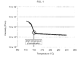
- Fig. 1 as a concept diagram with respect to the characteristics of the stampable sheet, when the temperature becomes high, the matrix resin melts at a certain temperature and the viscosity exhibits an approximately constant value at a temperature higher than the certain temperature. This temperature at which the matrix resin begins to melt can be perceived as a solidification start temperature of the matrix resin during a step of lowering the temperature from the molten state.
- the stampable sheet viscosity ⁇ which exhibits an approximately constant value regardless of the temperature change as described above, is defined as a viscosity at a temperature of the solidification start temperature of the matrix resin + 50°C, and the stampable sheet viscosity ⁇ , which can be thus perceived, is defined in the above-described range using the viscosity ⁇ 0 of the matrix resin.
- the viscosity ⁇ 0 of the matrix resin can be determined as shown in Fig. 2 . Namely, when the viscosity ⁇ of a stampable sheet is measured (measured points: indicated as black square points) in relation to the Vf (carbon fiber content (%)per unit volume of the stampable sheet), as shown in Fig.
- an approximately linear characteristic line can be obtained in a semilogarithmic graph.
- the range of the viscosity ⁇ of a stampable sheet is defined as described above relatively to the thus determined viscosity ⁇ 0 of the matrix resin.
- the range of the viscosity ⁇ of a stampable sheet defined in the present invention is a range depicted as a region R surrounded by the line of the viscosity ⁇ 0 of the matrix resin (depicted as a dotted line) and the characteristic line of the viscosity ⁇ (depicted as a solid line) in Fig. 2 .
- the carbon fibers used in the present invention are not particularly restricted, high-strength and high-elastic modulus carbon fibers can be used, and one kind of carbon fibers may be used or two or more kinds of carbon fibers may be used together.
- carbon fibers such as PAN-based, pitch-based and rayon-based ones can be exemplified.
- PAN-based carbon fibers are more preferable.
- the density of carbon fibers is preferably in a range of 1.65 to 1.95 g/cm 3 , and more preferably in a range of 1.70 to 1.85 g/cm 3 . If the density is too high, the lightness in weight of a carbon fiber-reinforced plastic obtained is poor, and if too low, there is a possibility where the mechanical properties of a carbon fiber-reinforced plastic obtained become low.
- the carbon fibers are preferably formed as a bundle from the viewpoint of productivity, and it is preferred that the number of single fibers in the bundle is many.
- the number of single fibers for the carbon fiber bundle can be employed within a range of 1,000 to 350,000, and in particular, it is preferably employed within a range of 10,000 to 100,000.
- the carbon fiber bundle is required to satisfy the conditions defined in the present invention.
- the single fiber flexural stiffness of carbon fibers is, as aforementioned, preferably in a range of 1.0 ⁇ 10 -11 to 2.8 ⁇ 10 -11 Pa ⁇ m 4 , and more preferably in a range of 1.0 ⁇ 10 -11 to 1.5 ⁇ 10 -11 Pa ⁇ m 4 .
- Such a single fiber flexural stiffness in the above-described range makes it possible, in the process for manufacturing carbon fiber aggregates described later, to stabilize the quality of carbon fiber aggregates obtained.
- the carbon fibers are surface treated.
- a method of the surface treatment there are electrolytic treatment, ozone treatment, ultraviolet treatment, etc.
- a sizing agent may be provided to the carbon fibers.
- a compound having a functional group such as an epoxy group, a urethane group, an amino group, and a carboxyl group can be used, and one kind or two or more kinds of these compounds may be used.
- a treatment method is employed wherein a liquid containing a sizing agent (a sizing liquid) is provided after drying wet carbon fiber bundles which are wetted by water and have a moisture content of about 20 to about 80 wt% by generally known surface treatment process and washing process.
- a sizing liquid a sizing liquid
- the method for providing a sizing agent is not particularly restricted, for example, typical examples of the method include a method for dipping the fibers into a sizing liquid via rollers, a method for bringing the fibers into contact with a roller adhered with a sizing agent, and a method for spraying an atomized sizing agent.
- a continuous type is preferred because it provides a good productivity and helps to minimize the degree of variation.
- the temperature and the time for drying should be adjusted depending upon the adhesion amount of the compound, from the viewpoints of completely removing the solvent used for providing the sizing agent, shortening the time required for the drying, on the other hand, preventing the heat deterioration of the sizing agent and preventing the carbon fiber bundles from being grown stiff and being deteriorated with the bundle spreading property, the temperature for drying is preferably 150°C or higher and 350°C or lower, and more preferably 180°C or higher and 250°C or lower.
- the adhesion amount of a sizing agent relative to the mass of only the carbon fibers is preferably 0.01 mass% or more and 10 mass% or less, more preferably 0.05 mass% or more and 5 mass% or less, and further preferably 0.1 mass% or more and 5 mass% or less. If less than 0.01 mass%, the effect for improving the adhesive property is hardly exhibited. If more than 10 mass%, there is a possibility where the properties of a molded article may be reduced.
- thermoplastic resin is used as a matrix resin.
- the material of the thermoplastic matrix resin is not particularly restricted, and it can be appropriately selected within a range that does not greatly reduce the mechanical properties of the carbon fiber-reinforced plastic as a molded article.
- a polyolefin-based resin such as polyethylene or polypropylene
- a polyamide-based resin such as nylon 6 or nylon 6,6
- a polyester-based resin such as polyethylene terephthalate or polybutylene terephthalate
- a resin such as a polyphenylene sulfide, a polyetherketone, a polyethersulfone, or an aromatic polyamide
- the thermoplastic resin preferably comprises any of polyamide, polypropylene and polyphenylene sulfide.
- Typical examples of the process for obtaining carbon fiber aggregates include carding and air laid.
- the carding mentioned in the present invention means an operation for arranging the direction of discontinuous fibers or unraveling fibers by applying a shear force in an approximately same direction to the aggregates of discontinuous carbon fibers with a comb-like member. Generally, it is performed using a carding machine equipped with a roll having many needle-like projections on the surface and/or a roll wound with a metallic wire having saw blade-like projections.
- the time (residence time) during which carbon fibers are present in the carding machine for the purpose of preventing the carbon fibers from being folded. More specifically, it is preferred to transfer the carbon fibers existing on the wires wound onto a cylinder roll of a carding machine to a doffer roll in minimal time. Therefore, in order to accelerate such a transfer, it is preferred to rotate the cylinder roll at a high rotational speed, for example, 250 rpm or higher. Further, for the same reason, it is preferred that the surface speed of the doffer roll is set at a high speed, for example, 10m/min. or higher.
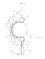
- carding machine 1 mainly comprises a cylinder roll 2, a take-in roll 3 provided at an upstream side and closely to the outer circumferential surface of the cylinder roll 2, a doffer roll 4 provided closely to the outer circumferential surface of the cylinder roll 2 at a downstream side which is a side opposite to the side of the take-in roll 3, a plurality of worker rolls 5 provided closely to the outer circumferential surface of the cylinder roll 2 between the take-in roll 3 and the doffer roll 4, stripper rolls 6 provided closely to the worker rolls 5, a feed roll 7 provided closely to the take-in roll 3, and a belt conveyer 8.
- Discontinuous carbon fiber bundles 9 are supplied to belt conveyer 8, and the carbon fiber bundles 9 are introduced onto the outer circumferential surface of cylinder roll 2 through the outer circumferential surface of feed roll 7 and then through the outer circumferential surface of take-in roll 3. Up to this stage, the carbon fiber bundles 9 are refined and become floc-like aggregates of carbon fiber bundles. Although a part of the floc-like aggregates of carbon fiber bundles introduced onto the outer circumferential surface of cylinder roll wind around the outer circumferential surface of worker rolls 5, these carbon fibers are stripped off by stripper rolls 6 and returned again onto the outer circumferential surface of the cylinder roll 2.
- air laid it is not particularly restricted too, and a general method can be used.
- general air laid processes include Honshu Paper process, Kroyer process, Danweb process, J&J process, KC process, Scott process, etc. (refer to "Base and application of non-woven fabric” (Non-woven fabric seminar in Japan Fibrous Machine Society, published in 1993 )).
- the examples include a process having a step of introducing cut carbon fiber bundle single materials or cut carbon fiber bundles and thermoplastic resin fibers into a tube, a step of blowing compressed air to refine fibers, and a step of obtaining carbon fiber aggregates which are dispersed and fixed; and a process having a step of refining cut carbon fiber bundle single materials or cut carbon fiber bundles and thermoplastic resin fibers by a refining means (for example, a pin cylinder) to form a carbon fiber nonwoven fabric as carbon fiber aggregates.
- a refining means for example, a pin cylinder
- Fig. 4 is a schematic configuration diagram showing an example of an air laid machine.
- air laid machine 20 has drums 21 rotated in directions reverse to each other, each formed in a cylinder shape and having small holes, pin cylinders 22 provided in the respective drums 21, wires 23 running under the drums 21, and suction box 24 provided under the wires 23.
- carbon fiber bundle single materials or carbon fiber bundles and thermoplastic resin fibers are supplied to air laid machine 20
- these fibers are air transported to drums 21 together with a large amount of air, they are refined by pin cylinders 22 in drums 21, discharged from the small holes, and they drop onto wires 23 running thereunder.
- the air used for the air transportation is sucked into suction box 24, and only refined carbon fiber bundle single materials or refined carbon fiber bundles and thermoplastic resin fibers are left on wires 23 to form a carbon fiber nonwoven fabric.
- the carbon fiber aggregates mean aggregates which are in a state where discontinuous carbon fiber bundles are refined and oriented by the above-described carding or air laid, and in which their configuration is maintained by entanglement or friction between fibers.
- Examples of such carbon fiber aggregates include a thin sheet-like web and a nonwoven fabric made of laminated webs that are, when necessary, entangled or adhered together.
- the carbon fiber aggregates may comprise only carbon fiber bundle single materials, or may include carbon fiber bundles and thermoplastic resin fibers. It is preferred to add thermoplastic resin fibers because it makes it possible to prevent carbon fibers from fracturing in the carding or air laid process. Carbon fibers are difficult to twine around and liable to break, because they are rigid and brittle. Therefore, carbon fiber aggregates consisting of only carbon fibers have potential problems that they are liable to be cut off and the carbon fibers are liable to fall out. Carbon fiber aggregates containing thermoplastic resin fibers, which are flexible, resistant to breakage and liable to twine, make it possible to form carbon fiber aggregates having a high uniformity.
- the ratio of carbon fiber content in the carbon fiber aggregates is preferably in a range of 20-95 wt%, more preferably in a range of 50-95 wt%, and further preferably in a range of 70-95 wt%. If the ratio of carbon fiber content is too low, it becomes difficult to obtain high mechanical properties when manufacturing carbon fiber composite material. On the other hand, if the ratio of carbon fiber content is too high, the above-described effect to promote the uniformity of carbon fiber aggregates cannot be obtained.
- the fiber length of thermoplastic resin fibers are not particularly limited as long as it is in a range to achieve the object of the present invention, such as configuration preservation of carbon fiber aggregates and prevention of fallout of carbon fibers.
- thermoplastic resin fibers having a fiber length of approximately 10-100 mm can be used.
- the fiber length of thermoplastic resin fibers can be determined in relation to the fiber length of carbon fibers. For example, a greater tension is applied to a fiber having a longer fiber length at the time of elongating carbon fiber aggregates.
- thermoplastic resin fibers for the objective of enhancing the effect of tangle due to the thermoplastic resin fibers.
- the degree of the crimp is not particularly limited as long as it is in a range capable of achieving the objective of the present invention, and generally, thermoplastic resin fibers having a number of crimps in a range of approximately 5 to 25 crests per 25 mm and a rate of crimp in a range of approximately 3 to 30% can be used.
- thermoplastic resin fibers are not particularly restricted, and it can be selected suitably within a range that does not greatly reduce the mechanical properties of the carbon fiber composite material.
- fibers which are prepared by spinning a resin such as a polyolefin-group resin such as polyethylene or polypropylene, a polyamide-group resin such as nylon 6 or nylon 6,6, a polyester-group resin such as polyethylene terephthalate or polybutylene terephthalate, a polyetherketone, a polyethersulfone or an aromatic polyamide. It is preferred that such a material for thermoplastic resin fibers is appropriately selected in accordance with the combination with a matrix resin.
- thermoplastic resin fibers prepared using the same resin as a matrix resin a resin having a compatibility with a matrix resin or a resin having a high adhesive property with a matrix resin is preferred, because the mechanical properties of a carbon fiber-reinforced plastic are not lowered.
- the thermoplastic resin fibers are preferred to be composed of at least one kind of fibers selected from the group consisting of polyamide fibers, polyphenylene sulfide fibers, polypropylene fibers, polyetheretherketone fibers and phenoxy resin fibers.
- a method may be employed wherein carbon fiber aggregates containing thermoplastic resin fibers are prepared and the thermoplastic resin fibers contained in the carbon fiber aggregates are used as the matrix resin as they are, or a method may also be employed wherein carbon fiber aggregates not containing thermoplastic resin fibers are used as a raw material, and a matrix resin is impregnated at an arbitrary stage for producing a carbon fiber composite material. Further, even in case where carbon fiber aggregates containing thermoplastic resin fibers are used as the raw material, a matrix resin can be impregnated at an arbitrary stage for producing a carbon fiber composite material.
- a resin forming thermoplastic resin fibers and a matrix resin may be an identical resin, and may be resins different from each other. In case where the resin forming thermoplastic resin fibers and the matrix resin are different from each other, it is preferred that both resins have a compatibility or a high affinity.
- thermoplastic resin as a matrix resin is impregnated into the above-described carbon fiber aggregates, and the impregnation step for manufacturing the carbon fiber composite material can be carried out using a press machine having a heating function.
- the press machine is not particularly restricted as long as it can realize temperature and pressure required for the impregnation of the matrix resin, a usual press machine having a plane-like platen moved vertically, or a so-called double belt press machine having a mechanism for running a pair of endless steel belts can be used.
- the matrix resin is prepared in a sheet-like form such as a film, a nonwoven fabric or a woven fabric, it is laminated with the carbon fiber aggregates, and at that condition, the matrix resin can be melted and impregnated using the above-described press machine.
- a method can also be employed wherein discontinuous fibers are prepared using a matrix resin, by mixing them and inorganic fibers at a step for making carbon fiber aggregates, carbon fiber aggregates containing the matrix resin and the inorganic fibers are prepared, and the carbon fiber aggregates are heated and pressed using the press machine and the like.
- the carbon fiber content Vf (%) per unit volume of a stampable sheet comprising carbon fiber composite material is preferably in a range of 5 ⁇ Vf ⁇ 80 (%), more preferably in a range of 5 ⁇ Vf ⁇ 70 (%), and further preferably in a range of 10 ⁇ Vf ⁇ 50 (%). If the value of Vf becomes less than 5%, there is a fear that the reinforcing effect by the carbon fibers may become small. Further, if the value of Vf becomes 80% or more, it becomes difficult to secure high flowability and there is a fear that it may become difficult to mold the stampable sheet.
- D is a diameter of carbon fibers
- F is a fineness of carbon fibers
- x n is a number of fibers forming a carbon fiber bundle.
- the determination is carried out at a condition where fiber bundles in which the value of Mn/(Ln x D) is less than 8.5 x 10 -1 mg/mm 2 are referred to as carbon fiber bundles (A) and the total weight of the carbon fiber bundles (A) is referred to as M A .
- the determination is carried out at a condition where carbon fiber bundles in which Mn/(Ln x D) is 8.5 x 10 -1 mg/mm 2 or more are referred to as carbon fiber bundles (B), the total weight of the carbon fiber bundles (B) is referred to as M B and the total number of the bundles is referred to as N B .
- M B the total weight of the carbon fiber bundles
- N B the total number of the bundles
- Z M A /(M A + M B ) x 100 (wt%) is calculated to obtain the ratio Z of carbon fiber bundles (A) to the total weight of carbon fibers.
- the viscosity is determined using APA2000 (supplied by ALPHA TECHNOLOGIES, Inc.) as follows: a sample having a size of 4.3cm 3 is interposed between parallel plates, the temperature is raised to a temperature of the melting point +60 °C, the viscosity is measured under conditions where the frequency is 1Hz and the strain is 5% while cooling down the temperature at a speed of 10 °C /min., and thereafter the viscosity of the sample is determined as a value of viscosity (Pa ⁇ s) at the solidification start temperature at which the viscosity begins to increase sharply.
- APA2000 supplied by ALPHA TECHNOLOGIES, Inc.
- a sample of about 2g was cut off from a molded article of a stampable sheet, and the mass thereof was determined. Thereafter, the sample was heated in an electric furnace heated at 500°C for one hour to burn off organic substances such as matrix resin. After cooled down to room temperature, the mass of the residual carbon fibers was determined. The rate of the mass of the carbon fibers to the mass of the sample before being burnt off with organic substances such as matrix resin was determined, and it was defined as the percentage content of carbon fibers.
- a flexural strength was determined on the basis of JIS-K7171.
- the CV value coefficient of variation [%]
- the variance of the flexural strength was small and judged as 'good ( ⁇ )'; and, in a case where the CV value was 5 % or more, the variance of the flexural strength was large and judged as 'bad ( ⁇ )'
- E single fiber elastic modulus
- I geometrical moment of inertia
- the cross section of a fiber was supposed as a true circle, the geometrical moment of inertia I was determined from the fiber diameter D, and the flexural stiffness was determined from the single fiber tensile elastic modulus E and the geometrical moment of inertia I.
- Carbon fibers and carbon fiber bundles (before cutting) used in Examples and Comparative Examples of the present invention will be explained.
- the carbon fiber bundle (1) was cut at a fiber length of 25 mm, the cut carbon fiber bundles and nylon 6 short fibers (fineness of short fiber: 1.7 dtex, cut length: 51 mm, number of crimps: 12 crests per 25 mm, rate of crimp: 15%) were mixed at a mass ratio of 90:10, and the mixture was introduced into a carding machine.
- the web having come out was cross wrapped to form sheet-like carbon fiber aggregates comprising carbon fibers and nylon 6 fibers and having an areal weight of 100g/cm 2 .
- the ratio Z of carbon fiber bundles (A) to the total weight of carbon fibers was 85 wt%
- the ratio Y of carbon fiber bundles (B) to the total weight of carbon fibers was 15 wt%
- the average value X of Mn/Ln was 0.01 mg/mm
- the average value x of number of fibers forming a fiber bundle was 144
- the standard variation ⁇ of number of fibers forming a fiber bundle was 88.
- CM1001 nylon resin
- ⁇ r 2.3
- the average value of the flexural strengths in 0° and 90° directions was 365 MPa, and the CV value was less than 5%.
- a flat plate of carbon fiber composite material was obtained in a manner similar to that of Example 1 except that the carbon fiber bundle (1) was cut at a fiber length of 15 mm, carbon fiber aggregates in which the ratio Z of carbon fiber bundles (A) to the total weight of carbon fibers was 65 wt%, the ratio Y of carbon fiber bundles (B) to the total weight of carbon fibers was 35 wt%, the average value X of Mn/Ln was 0.017 mg/mm, the average value xof number of fibers forming a fiber bundle was 246 and the standard variation ⁇ of number of carbon fibers forming a fiber bundle was 110 were stacked to obtain a flat plate of carbon fiber composite material having a thickness of 2 mm.
- the average value of the flexural strengths in 0° and 90° directions was 360 MPa, and the CV value of the flexural strength was less than 5%.
- Example 2 They were carried out under conditions similar to Example 2 except that the average value X of Mn/Ln, the average value x of number of fibers forming a fiber bundle, the standard variation ⁇ of number of fibers forming a fiber bundle, the Vf, etc. were changed from Example 2. The results were shown in Table 1.
- CM1041 nylon resin
- ⁇ r 4.3
- the average value of the flexural strengths in 0° and 90° directions was 350 MPa, and the CV value of the flexural strength was less than 5%.
- Example 2 It was carried out in a manner similar to Example 1 except that the carbon fiber bundle (2) was cut at a fiber length of 15 mm, carbon fiber aggregates in which the ratio Z of carbon fiber bundles (A) to the total weight of carbon fibers was 50 wt%, the ratio Y of carbon fiber bundles (B) to the total weight of carbon fibers was 50 wt%, the average value X of Mn/Ln was 0.025 mg/mm, the average value x of number of fibers forming a fiber bundle was 585 and the standard variation ⁇ of number of carbon fibers forming a fiber bundle was 350 were stacked, and a flat plate of carbon fiber composite material having a thickness of 2 mm was obtained.
- the average value of the flexural strengths in 0° and 90° directions was 400 MPa, and the CV value of the flexural strength was less than 5%.
- the carbon fiber bundle (1) was cut at a fiber length of 15 mm, the cut carbon fiber bundles and nylon 6 short fibers (fineness of short fiber: 1.7 dtex, cut length: 10 mm) were mixed at a mass ratio of 80:20, and the mixture was introduced into an air laid machine.
- the nonwoven fabric having come out was heat treated to form sheet-like carbon fiber aggregates comprising carbon fibers and nylon 6 fibers and having an areal weight of 200g/cm 2 .
- the ratio Z of carbon fiber bundles (A) to the total weight of carbon fibers was 30 wt%
- the ratio Y of carbon fiber bundles (B) to the total weight of carbon fibers was 70 wt%
- the average value X of Mn/Ln was 0.028 mg/mm
- the average value x of number of fibers forming a fiber bundle was 400 and the standard variation ⁇ of number of fibers forming a fiber bundle was 315.
- the winding direction of the sheet-like carbon fiber aggregates was referred to as 0°, sheets of the carbon fiber aggregates were stacked, and further, after a nonwoven fabric comprising co-polymerized nylon resin ("E3500", supplied by Toray Industries, Inc.) was stacked so that the volume ratio of the carbon fibers to the thermoplastic resin fibers became 20:80 as the whole of the stacked carbon fiber aggregates, the whole was nipped by stainless plates, and after preheating at 250°C for 90 seconds, it was hot pressed at 250°C for 180 seconds while being applied with a pressure of 1.0 MPa.
- E3500 co-polymerized nylon resin
- Example 2 They were carried out in a manner similar to Example 1 except that the ratio Z of carbon fiber bundles (A) to the total weight of carbon fibers, the ratio Y of carbon fiber bundles (B), the average value X of Mn/Ln, the average value x of number of fibers forming a fiber bundle, the standard variation ⁇ of number of fibers forming a fiber bundle, the Vf, the resin, etc. were changed from Example 1. The results were shown in Table 2.
- CM1001 nylon resin
- Example 2 It was carried out in a manner similar to Example 1 except that the carbon fiber bundle (1) was cut at a fiber length of 15 mm, carbon fiber aggregates in which the ratio Z of carbon fiber bundles (A) to the total weight of carbon fibers was 95 wt%, the average value X of Mn/Ln was 0.01 mg/mm, the average value x of number of fibers forming a fiber bundle was 140 and the standard variation ⁇ of number of carbon fibers forming a fiber bundle was 40 were stacked to obtain a flat plate of carbon fiber composite material having a thickness of 2 mm.
- the average value of the flexural strengths in 0° and 90° directions was 365 MPa, and the CV value of the flexural strength was less than 5%.
- the stampable sheet according to the present invention can be applied for manufacturing any carbon fiber reinforced molded article required with combination of high flowability and mechanical properties and few variations in mechanical properties, that have not been achieved by the conventional technologies.
Landscapes
- Chemical & Material Sciences (AREA)
- Engineering & Computer Science (AREA)
- Chemical Kinetics & Catalysis (AREA)
- Health & Medical Sciences (AREA)
- Medicinal Chemistry (AREA)
- Polymers & Plastics (AREA)
- Organic Chemistry (AREA)
- Materials Engineering (AREA)
- Manufacturing & Machinery (AREA)
- Inorganic Chemistry (AREA)
- Mechanical Engineering (AREA)
- Textile Engineering (AREA)
- Reinforced Plastic Materials (AREA)
- Manufacture Of Macromolecular Shaped Articles (AREA)
- Compositions Of Macromolecular Compounds (AREA)
- Nonwoven Fabrics (AREA)
Applications Claiming Priority (2)
| Application Number | Priority Date | Filing Date | Title |
|---|---|---|---|
| JP2012235635 | 2012-10-25 | ||
| PCT/JP2013/077973 WO2014065161A1 (ja) | 2012-10-25 | 2013-10-15 | スタンパブルシート |
Publications (2)
| Publication Number | Publication Date |
|---|---|
| EP2913170A1 true EP2913170A1 (de) | 2015-09-02 |
| EP2913170A4 EP2913170A4 (de) | 2016-04-20 |
Family
ID=50544541
Family Applications (1)
| Application Number | Title | Priority Date | Filing Date |
|---|---|---|---|
| EP13848671.7A Withdrawn EP2913170A4 (de) | 2012-10-25 | 2013-10-15 | Ausstanzbares blatt |
Country Status (6)
| Country | Link |
|---|---|
| US (1) | US20150292146A1 (de) |
| EP (1) | EP2913170A4 (de) |
| JP (1) | JPWO2014065161A1 (de) |
| KR (1) | KR20150079561A (de) |
| CN (1) | CN104602882B (de) |
| WO (1) | WO2014065161A1 (de) |
Cited By (1)
| Publication number | Priority date | Publication date | Assignee | Title |
|---|---|---|---|---|
| EP2857439A4 (de) * | 2012-05-29 | 2015-11-18 | Toray Industries | Kohlefaser-verbundmaterial |
Families Citing this family (1)
| Publication number | Priority date | Publication date | Assignee | Title |
|---|---|---|---|---|
| KR101975886B1 (ko) | 2014-06-24 | 2019-05-07 | 코오롱인더스트리 주식회사 | 활성탄소섬유 원단용 필라멘트 웹 타입 전구체 원단 및 그의 제조방법 |
Citations (5)
| Publication number | Priority date | Publication date | Assignee | Title |
|---|---|---|---|---|
| JP2002212311A (ja) | 2001-01-15 | 2002-07-31 | Japan Vilene Co Ltd | 炭素繊維強化スタンパブルシート、その製造方法、及びその成形品 |
| JP2004043985A (ja) | 2002-07-09 | 2004-02-12 | Yuuhou:Kk | 不織布およびシート状成形材料の製造方法 |
| JP2012127044A (ja) | 2010-11-24 | 2012-07-05 | Toray Ind Inc | 繊維材料およびその製造方法 |
| WO2012105080A1 (ja) | 2011-02-01 | 2012-08-09 | 帝人株式会社 | ランダムマット、および強化繊維複合材料 |
| WO2013118689A1 (ja) | 2012-02-09 | 2013-08-15 | 東レ株式会社 | 炭素繊維複合材料 |
Family Cites Families (12)
| Publication number | Priority date | Publication date | Assignee | Title |
|---|---|---|---|---|
| US6066395A (en) * | 1997-05-23 | 2000-05-23 | Toray Industries, Inc. | Chopped carbon fibers and a production process there of |
| ES2624694T3 (es) * | 2007-03-20 | 2017-07-17 | Toray Industries, Inc. | Material de moldeo, preimpregnado, material compuesto reforzado con fibras y proceso para la producción de un material de base de moldeo reforzado con fibras |
| JP5569708B2 (ja) | 2009-01-15 | 2014-08-13 | 三菱レイヨン株式会社 | シートモールディングコンパウンドの製造方法 |
| JP4811532B2 (ja) * | 2009-03-24 | 2011-11-09 | 東レ株式会社 | 繊維強化複合材料用エポキシ樹脂組成物、プリプレグおよび繊維強化複合材料 |
| CN102098194B (zh) * | 2009-12-10 | 2014-02-05 | 中兴通讯股份有限公司 | 一种在局域网络中实现时间同步的方法及系统 |
| ES2717884T3 (es) * | 2010-01-20 | 2019-06-26 | Toray Industries | Haces de fibras de carbono |
| JP2011157524A (ja) * | 2010-02-03 | 2011-08-18 | Toray Ind Inc | 繊維強化熱可塑性プラスチックおよびその製造方法 |
| JP5576147B2 (ja) * | 2010-03-01 | 2014-08-20 | 帝人株式会社 | 炭素繊維複合材料 |
| JP2011178890A (ja) * | 2010-03-01 | 2011-09-15 | Teijin Ltd | 炭素繊維複合材料 |
| JP2012235635A (ja) * | 2011-05-02 | 2012-11-29 | Merstech Inc | 昇圧装置、昇圧方法、及び、プログラム |
| JP5920227B2 (ja) * | 2011-05-31 | 2016-05-18 | 東レ株式会社 | 炭素繊維強化プラスチックの製造方法 |
| JP5722732B2 (ja) * | 2011-08-31 | 2015-05-27 | 帝人株式会社 | 熱可塑性複合材料形成用等方性ランダムマットの製造方法 |
-
2013
- 2013-10-15 EP EP13848671.7A patent/EP2913170A4/de not_active Withdrawn
- 2013-10-15 JP JP2013554516A patent/JPWO2014065161A1/ja active Pending
- 2013-10-15 KR KR1020157006608A patent/KR20150079561A/ko not_active Withdrawn
- 2013-10-15 CN CN201380046170.7A patent/CN104602882B/zh not_active Expired - Fee Related
- 2013-10-15 US US14/435,831 patent/US20150292146A1/en not_active Abandoned
- 2013-10-15 WO PCT/JP2013/077973 patent/WO2014065161A1/ja not_active Ceased
Patent Citations (7)
| Publication number | Priority date | Publication date | Assignee | Title |
|---|---|---|---|---|
| JP2002212311A (ja) | 2001-01-15 | 2002-07-31 | Japan Vilene Co Ltd | 炭素繊維強化スタンパブルシート、その製造方法、及びその成形品 |
| JP2004043985A (ja) | 2002-07-09 | 2004-02-12 | Yuuhou:Kk | 不織布およびシート状成形材料の製造方法 |
| JP2012127044A (ja) | 2010-11-24 | 2012-07-05 | Toray Ind Inc | 繊維材料およびその製造方法 |
| WO2012105080A1 (ja) | 2011-02-01 | 2012-08-09 | 帝人株式会社 | ランダムマット、および強化繊維複合材料 |
| EP2671991A1 (de) | 2011-02-01 | 2013-12-11 | Teijin Limited | Willkürliche matte und faserverstärktes verbundmaterial |
| WO2013118689A1 (ja) | 2012-02-09 | 2013-08-15 | 東レ株式会社 | 炭素繊維複合材料 |
| EP2813532A1 (de) | 2012-02-09 | 2014-12-17 | Toray Industries, Inc. | Kohlefaser-verbundmaterial |
Non-Patent Citations (1)
| Title |
|---|
| See also references of WO2014065161A1 |
Cited By (1)
| Publication number | Priority date | Publication date | Assignee | Title |
|---|---|---|---|---|
| EP2857439A4 (de) * | 2012-05-29 | 2015-11-18 | Toray Industries | Kohlefaser-verbundmaterial |
Also Published As
| Publication number | Publication date |
|---|---|
| CN104602882B (zh) | 2016-08-24 |
| JPWO2014065161A1 (ja) | 2016-09-08 |
| CN104602882A (zh) | 2015-05-06 |
| KR20150079561A (ko) | 2015-07-08 |
| WO2014065161A1 (ja) | 2014-05-01 |
| WO2014065161A9 (ja) | 2015-03-12 |
| EP2913170A4 (de) | 2016-04-20 |
| US20150292146A1 (en) | 2015-10-15 |
Similar Documents
| Publication | Publication Date | Title |
|---|---|---|
| US9850368B2 (en) | Carbon fiber composite material | |
| JP5995150B2 (ja) | 炭素繊維複合材料 | |
| JP5843048B1 (ja) | スタンパブルシート | |
| KR20230145233A (ko) | 분말 형태의 열가소성 폴리머로 예비 함침된 섬유성 재료를 제조하기 위한 방법 | |
| WO2008149615A9 (ja) | チョップド繊維束、成形材料、および、繊維強化プラスチック、ならびに、これらの製造方法 | |
| EP2980309A1 (de) | Kohlenstofffaservlies | |
| JP6331123B2 (ja) | 炭素繊維複合材料 | |
| CN105073847B (zh) | 可冲压片材 | |
| JP6083239B2 (ja) | 繊維強化プラスチックおよびその製造方法 | |
| JP2014196584A (ja) | 不織布の製造方法および複合材料の製造方法 | |
| US20150292146A1 (en) | Stampable sheet | |
| JP6540005B2 (ja) | スタンパブル基材の製造方法 | |
| JP6458589B2 (ja) | シート材料、一体化成形品および一体化成形品の製造方法 | |
| JP6201630B2 (ja) | 炭素繊維マットおよびその製造方法 |
Legal Events
| Date | Code | Title | Description |
|---|---|---|---|
| TPAB | Information related to observations by third parties deleted |
Free format text: ORIGINAL CODE: EPIDOSDTIPA |
|
| TPAC | Observations filed by third parties |
Free format text: ORIGINAL CODE: EPIDOSNTIPA |
|
| PUAI | Public reference made under article 153(3) epc to a published international application that has entered the european phase |
Free format text: ORIGINAL CODE: 0009012 |
|
| 17P | Request for examination filed |
Effective date: 20150415 |
|
| AK | Designated contracting states |
Kind code of ref document: A1 Designated state(s): AL AT BE BG CH CY CZ DE DK EE ES FI FR GB GR HR HU IE IS IT LI LT LU LV MC MK MT NL NO PL PT RO RS SE SI SK SM TR |
|
| AX | Request for extension of the european patent |
Extension state: BA ME |
|
| TPAB | Information related to observations by third parties deleted |
Free format text: ORIGINAL CODE: EPIDOSDTIPA |
|
| TPAC | Observations filed by third parties |
Free format text: ORIGINAL CODE: EPIDOSNTIPA |
|
| DAX | Request for extension of the european patent (deleted) | ||
| RA4 | Supplementary search report drawn up and despatched (corrected) |
Effective date: 20160317 |
|
| RIC1 | Information provided on ipc code assigned before grant |
Ipc: C08J 5/06 20060101ALI20160311BHEP Ipc: B29B 11/16 20060101AFI20160311BHEP Ipc: B29C 70/12 20060101ALI20160311BHEP |
|
| TPAC | Observations filed by third parties |
Free format text: ORIGINAL CODE: EPIDOSNTIPA |
|
| 17Q | First examination report despatched |
Effective date: 20170313 |
|
| TPAC | Observations filed by third parties |
Free format text: ORIGINAL CODE: EPIDOSNTIPA |
|
| STAA | Information on the status of an ep patent application or granted ep patent |
Free format text: STATUS: THE APPLICATION IS DEEMED TO BE WITHDRAWN |
|
| 18D | Application deemed to be withdrawn |
Effective date: 20180515 |