EP2913184A2 - Method for applying an adhesive to a laminating film, method for laminating a load bearing element, and laminating device - Google Patents
Method for applying an adhesive to a laminating film, method for laminating a load bearing element, and laminating device Download PDFInfo
- Publication number
- EP2913184A2 EP2913184A2 EP15000483.6A EP15000483A EP2913184A2 EP 2913184 A2 EP2913184 A2 EP 2913184A2 EP 15000483 A EP15000483 A EP 15000483A EP 2913184 A2 EP2913184 A2 EP 2913184A2
- Authority
- EP
- European Patent Office
- Prior art keywords
- adhesive
- laminating film
- film
- laminating
- grid
- Prior art date
- Legal status (The legal status is an assumption and is not a legal conclusion. Google has not performed a legal analysis and makes no representation as to the accuracy of the status listed.)
- Withdrawn
Links
Images


Classifications
-
- B—PERFORMING OPERATIONS; TRANSPORTING
- B32—LAYERED PRODUCTS
- B32B—LAYERED PRODUCTS, i.e. PRODUCTS BUILT-UP OF STRATA OF FLAT OR NON-FLAT, e.g. CELLULAR OR HONEYCOMB, FORM
- B32B37/00—Methods or apparatus for laminating, e.g. by curing or by ultrasonic bonding
- B32B37/12—Methods or apparatus for laminating, e.g. by curing or by ultrasonic bonding characterised by using adhesives
- B32B37/1284—Application of adhesive
- B32B37/1292—Application of adhesive selectively, e.g. in stripes, in patterns
-
- B—PERFORMING OPERATIONS; TRANSPORTING
- B29—WORKING OF PLASTICS; WORKING OF SUBSTANCES IN A PLASTIC STATE IN GENERAL
- B29C—SHAPING OR JOINING OF PLASTICS; SHAPING OF MATERIAL IN A PLASTIC STATE, NOT OTHERWISE PROVIDED FOR; AFTER-TREATMENT OF THE SHAPED PRODUCTS, e.g. REPAIRING
- B29C63/00—Lining or sheathing, i.e. applying preformed layers or sheathings of plastics; Apparatus therefor
- B29C63/0047—Preventing air-inclusions
-
- B—PERFORMING OPERATIONS; TRANSPORTING
- B32—LAYERED PRODUCTS
- B32B—LAYERED PRODUCTS, i.e. PRODUCTS BUILT-UP OF STRATA OF FLAT OR NON-FLAT, e.g. CELLULAR OR HONEYCOMB, FORM
- B32B37/00—Methods or apparatus for laminating, e.g. by curing or by ultrasonic bonding
- B32B37/0007—Methods or apparatus for laminating, e.g. by curing or by ultrasonic bonding involving treatment or provisions in order to avoid deformation or air inclusion, e.g. to improve surface quality
- B32B37/003—Methods or apparatus for laminating, e.g. by curing or by ultrasonic bonding involving treatment or provisions in order to avoid deformation or air inclusion, e.g. to improve surface quality to avoid air inclusion
-
- C—CHEMISTRY; METALLURGY
- C09—DYES; PAINTS; POLISHES; NATURAL RESINS; ADHESIVES; COMPOSITIONS NOT OTHERWISE PROVIDED FOR; APPLICATIONS OF MATERIALS NOT OTHERWISE PROVIDED FOR
- C09J—ADHESIVES; NON-MECHANICAL ASPECTS OF ADHESIVE PROCESSES IN GENERAL; ADHESIVE PROCESSES NOT PROVIDED FOR ELSEWHERE; USE OF MATERIALS AS ADHESIVES
- C09J7/00—Adhesives in the form of films or foils
- C09J7/20—Adhesives in the form of films or foils characterised by their carriers
-
- B—PERFORMING OPERATIONS; TRANSPORTING
- B32—LAYERED PRODUCTS
- B32B—LAYERED PRODUCTS, i.e. PRODUCTS BUILT-UP OF STRATA OF FLAT OR NON-FLAT, e.g. CELLULAR OR HONEYCOMB, FORM
- B32B37/00—Methods or apparatus for laminating, e.g. by curing or by ultrasonic bonding
- B32B37/12—Methods or apparatus for laminating, e.g. by curing or by ultrasonic bonding characterised by using adhesives
- B32B37/1207—Heat-activated adhesive
- B32B2037/1215—Hot-melt adhesive
-
- B—PERFORMING OPERATIONS; TRANSPORTING
- B32—LAYERED PRODUCTS
- B32B—LAYERED PRODUCTS, i.e. PRODUCTS BUILT-UP OF STRATA OF FLAT OR NON-FLAT, e.g. CELLULAR OR HONEYCOMB, FORM
- B32B2307/00—Properties of the layers or laminate
- B32B2307/70—Other properties
- B32B2307/724—Permeability to gases, adsorption
- B32B2307/7242—Non-permeable
-
- B—PERFORMING OPERATIONS; TRANSPORTING
- B32—LAYERED PRODUCTS
- B32B—LAYERED PRODUCTS, i.e. PRODUCTS BUILT-UP OF STRATA OF FLAT OR NON-FLAT, e.g. CELLULAR OR HONEYCOMB, FORM
- B32B2307/00—Properties of the layers or laminate
- B32B2307/70—Other properties
- B32B2307/732—Dimensional properties
- B32B2307/734—Dimensional stability
-
- B—PERFORMING OPERATIONS; TRANSPORTING
- B32—LAYERED PRODUCTS
- B32B—LAYERED PRODUCTS, i.e. PRODUCTS BUILT-UP OF STRATA OF FLAT OR NON-FLAT, e.g. CELLULAR OR HONEYCOMB, FORM
- B32B2309/00—Parameters for the laminating or treatment process; Apparatus details
- B32B2309/02—Temperature
-
- B—PERFORMING OPERATIONS; TRANSPORTING
- B32—LAYERED PRODUCTS
- B32B—LAYERED PRODUCTS, i.e. PRODUCTS BUILT-UP OF STRATA OF FLAT OR NON-FLAT, e.g. CELLULAR OR HONEYCOMB, FORM
- B32B2309/00—Parameters for the laminating or treatment process; Apparatus details
- B32B2309/60—In a particular environment
- B32B2309/68—Vacuum
-
- B—PERFORMING OPERATIONS; TRANSPORTING
- B32—LAYERED PRODUCTS
- B32B—LAYERED PRODUCTS, i.e. PRODUCTS BUILT-UP OF STRATA OF FLAT OR NON-FLAT, e.g. CELLULAR OR HONEYCOMB, FORM
- B32B2398/00—Unspecified macromolecular compounds
- B32B2398/20—Thermoplastics
-
- B—PERFORMING OPERATIONS; TRANSPORTING
- B32—LAYERED PRODUCTS
- B32B—LAYERED PRODUCTS, i.e. PRODUCTS BUILT-UP OF STRATA OF FLAT OR NON-FLAT, e.g. CELLULAR OR HONEYCOMB, FORM
- B32B2605/00—Vehicles
- B32B2605/003—Interior finishings
-
- B—PERFORMING OPERATIONS; TRANSPORTING
- B32—LAYERED PRODUCTS
- B32B—LAYERED PRODUCTS, i.e. PRODUCTS BUILT-UP OF STRATA OF FLAT OR NON-FLAT, e.g. CELLULAR OR HONEYCOMB, FORM
- B32B37/00—Methods or apparatus for laminating, e.g. by curing or by ultrasonic bonding
- B32B37/0046—Methods or apparatus for laminating, e.g. by curing or by ultrasonic bonding characterised by constructional aspects of the apparatus
- B32B37/0053—Constructional details of laminating machines comprising rollers; Constructional features of the rollers
-
- B—PERFORMING OPERATIONS; TRANSPORTING
- B32—LAYERED PRODUCTS
- B32B—LAYERED PRODUCTS, i.e. PRODUCTS BUILT-UP OF STRATA OF FLAT OR NON-FLAT, e.g. CELLULAR OR HONEYCOMB, FORM
- B32B37/00—Methods or apparatus for laminating, e.g. by curing or by ultrasonic bonding
- B32B37/10—Methods or apparatus for laminating, e.g. by curing or by ultrasonic bonding characterised by the pressing technique, e.g. using action of vacuum or fluid pressure
- B32B37/1009—Methods or apparatus for laminating, e.g. by curing or by ultrasonic bonding characterised by the pressing technique, e.g. using action of vacuum or fluid pressure using vacuum and fluid pressure
-
- B—PERFORMING OPERATIONS; TRANSPORTING
- B32—LAYERED PRODUCTS
- B32B—LAYERED PRODUCTS, i.e. PRODUCTS BUILT-UP OF STRATA OF FLAT OR NON-FLAT, e.g. CELLULAR OR HONEYCOMB, FORM
- B32B37/00—Methods or apparatus for laminating, e.g. by curing or by ultrasonic bonding
- B32B37/12—Methods or apparatus for laminating, e.g. by curing or by ultrasonic bonding characterised by using adhesives
- B32B37/1207—Heat-activated adhesive
-
- B—PERFORMING OPERATIONS; TRANSPORTING
- B32—LAYERED PRODUCTS
- B32B—LAYERED PRODUCTS, i.e. PRODUCTS BUILT-UP OF STRATA OF FLAT OR NON-FLAT, e.g. CELLULAR OR HONEYCOMB, FORM
- B32B38/00—Ancillary operations in connection with laminating processes
- B32B38/06—Embossing
-
- B—PERFORMING OPERATIONS; TRANSPORTING
- B32—LAYERED PRODUCTS
- B32B—LAYERED PRODUCTS, i.e. PRODUCTS BUILT-UP OF STRATA OF FLAT OR NON-FLAT, e.g. CELLULAR OR HONEYCOMB, FORM
- B32B7/00—Layered products characterised by the relation between layers; Layered products characterised by the relative orientation of features between layers, or by the relative values of a measurable parameter between layers, i.e. products comprising layers having different physical, chemical or physicochemical properties; Layered products characterised by the interconnection of layers
- B32B7/04—Interconnection of layers
- B32B7/12—Interconnection of layers using interposed adhesives or interposed materials with bonding properties
- B32B7/14—Interconnection of layers using interposed adhesives or interposed materials with bonding properties applied in spaced arrangements, e.g. in stripes
-
- B—PERFORMING OPERATIONS; TRANSPORTING
- B60—VEHICLES IN GENERAL
- B60R—VEHICLES, VEHICLE FITTINGS, OR VEHICLE PARTS, NOT OTHERWISE PROVIDED FOR
- B60R13/00—Elements for body-finishing, identifying, or decorating; Arrangements or adaptations for advertising purposes
- B60R13/02—Internal Trim mouldings ; Internal Ledges; Wall liners for passenger compartments; Roof liners
-
- B—PERFORMING OPERATIONS; TRANSPORTING
- B60—VEHICLES IN GENERAL
- B60R—VEHICLES, VEHICLE FITTINGS, OR VEHICLE PARTS, NOT OTHERWISE PROVIDED FOR
- B60R13/00—Elements for body-finishing, identifying, or decorating; Arrangements or adaptations for advertising purposes
- B60R13/02—Internal Trim mouldings ; Internal Ledges; Wall liners for passenger compartments; Roof liners
- B60R13/0256—Dashboard liners
-
- B—PERFORMING OPERATIONS; TRANSPORTING
- B60—VEHICLES IN GENERAL
- B60R—VEHICLES, VEHICLE FITTINGS, OR VEHICLE PARTS, NOT OTHERWISE PROVIDED FOR
- B60R13/00—Elements for body-finishing, identifying, or decorating; Arrangements or adaptations for advertising purposes
- B60R13/02—Internal Trim mouldings ; Internal Ledges; Wall liners for passenger compartments; Roof liners
- B60R13/0262—Mid-console liners
-
- C—CHEMISTRY; METALLURGY
- C09—DYES; PAINTS; POLISHES; NATURAL RESINS; ADHESIVES; COMPOSITIONS NOT OTHERWISE PROVIDED FOR; APPLICATIONS OF MATERIALS NOT OTHERWISE PROVIDED FOR
- C09J—ADHESIVES; NON-MECHANICAL ASPECTS OF ADHESIVE PROCESSES IN GENERAL; ADHESIVE PROCESSES NOT PROVIDED FOR ELSEWHERE; USE OF MATERIALS AS ADHESIVES
- C09J2301/00—Additional features of adhesives in the form of films or foils
- C09J2301/20—Additional features of adhesives in the form of films or foils characterized by the structural features of the adhesive itself
- C09J2301/204—Additional features of adhesives in the form of films or foils characterized by the structural features of the adhesive itself the adhesive coating being discontinuous
-
- Y—GENERAL TAGGING OF NEW TECHNOLOGICAL DEVELOPMENTS; GENERAL TAGGING OF CROSS-SECTIONAL TECHNOLOGIES SPANNING OVER SEVERAL SECTIONS OF THE IPC; TECHNICAL SUBJECTS COVERED BY FORMER USPC CROSS-REFERENCE ART COLLECTIONS [XRACs] AND DIGESTS
- Y10—TECHNICAL SUBJECTS COVERED BY FORMER USPC
- Y10T—TECHNICAL SUBJECTS COVERED BY FORMER US CLASSIFICATION
- Y10T156/00—Adhesive bonding and miscellaneous chemical manufacture
- Y10T156/17—Surface bonding means and/or assemblymeans with work feeding or handling means
- Y10T156/1702—For plural parts or plural areas of single part
- Y10T156/1744—Means bringing discrete articles into assembled relationship
-
- Y—GENERAL TAGGING OF NEW TECHNOLOGICAL DEVELOPMENTS; GENERAL TAGGING OF CROSS-SECTIONAL TECHNOLOGIES SPANNING OVER SEVERAL SECTIONS OF THE IPC; TECHNICAL SUBJECTS COVERED BY FORMER USPC CROSS-REFERENCE ART COLLECTIONS [XRACs] AND DIGESTS
- Y10—TECHNICAL SUBJECTS COVERED BY FORMER USPC
- Y10T—TECHNICAL SUBJECTS COVERED BY FORMER US CLASSIFICATION
- Y10T29/00—Metal working
- Y10T29/49—Method of mechanical manufacture
- Y10T29/49716—Converting
Definitions
- the present invention relates to a method for providing a laminating film with adhesive, a method for applying a hotmelt to a laminating film, the use of such a method, a system for laminating a carrier part with a laminating film and a method for retrofitting a plant.
- the invention relates to a method for laminating components with films, wherein an adhesive is applied in a grid pattern on the surface of the laminating film and / or the component, that after joining the film and the component of the adhesive between the film and the component is arranged and the areas between the adhesive applications form a channel system which ensures the uniform removal (removal of air by pulling and / or squeezing) of the air between the component and the film.
- the invention relates to a laminated molding, which is obtainable by the above-mentioned method and the use of an arranged between a component and a laminating adhesive grid to reduce or avoid air pockets in the lamination of the component with the laminating film.
- Vacuum laminating or variants such as the in-mold graining (IMG) process and / or pressing pressure are widely used in the industry.
- an air impermeable or limited air impermeable material eg, a decorative film
- the adhesive used can be used as a pre-coating on the film or be applied to the component.
- the film can be heated in this process and then applied by applying a negative pressure to the component.
- the heat energy necessary for the film deformation can also be used to activate the adhesive.
- a crucial condition for the process is the air permeability (vacuum capability) of the substrate to be laminated (component) in combination with an air-impermeable film. The latter can be achieved for example by an additional membrane.
- the vacuum holes allow the escape of air between the film and the component by applying a negative pressure or vacuum.
- a negative pressure or vacuum usually additionally a Kaschiernarbung is applied to the component, which allows for further air transport through the trenches of graining to the holes even after the "first contact" of the film with the component.
- this Kaschiernarbung on the component is technically complex and costly, especially since a sufficient graining typically requires 0.2 to 0.3 mm depth, resulting in a correspondingly higher material usage and also increases the overall weight of the component. This can affect up to 10% by weight of the component weight.
- the adhesive is applied by spraying onto the component.
- a paint-like adhesive application must be avoided, since this can lead to a clogging of the vacuum holes by the adhesive (for example, when using a dispersion or solvent adhesive).
- adhesive application e.g., a hot melt adhesive
- the hotmelt adhesive is heated with the film to the necessary film-typical deformation temperature (depending on the film 120 ° C to 210 ° C) and thus activated.
- the adhesive (usually a reactive or thermoplastic hot melt adhesive) is viscous-liquid. This also applies to the vacuum joining process.
- the viscous adhesive can very easily close the vacuum holes or the graves because of its flowability. This prevents the uniform extraction of air and can thus favor the formation of air pockets. This leads to visible but also invisible defects in the finished laminated molding.
- the object of the present invention is to provide an alternative or improvement to the prior art.
- the stated object solves a method for providing a laminating film with adhesive as a preparatory method step method of producing a laminated molding by means of a backing member, the liner and the adhesive, the adhesive to bond the B-side of the liner and a surface of the backing member, comprising the steps of: (a) applying the adhesive to the B-side; and (b) thereafter reshaping the adhesive by embossing a grid in the adhesive such that channels are formed with the grid before the adhesive is bonded to the surface of the support member.
- the "laminating film” may be a plastic film, preferably a plastic film based on polyvinyl chloride (PVC), polyolefins, thermoplastic polyolefins (TPO), polycarbonate, polyethers, polyesters, polyurethanes, poly (meth) acrylate, or combinations of copolymers and terpolymers thereof.
- PVC polyvinyl chloride
- TPO thermoplastic polyolefins
- polycarbonate polyethers
- polyesters polyurethanes
- poly (meth) acrylate poly (meth) acrylate
- other (decorative) materials are suitable such as foam films, textiles, metal foils, real leather, artificial leather and laminates of various of the above materials.
- the airtightness can be achieved by the use of additional membrane.
- the laminating film preferably has a thickness in the range of 0.1 mm or more and 7.0 mm or less, preferably 1.0 mm or more and 3.5 mm or less, more preferably 1.5 mm or more and 2.5 mm or less.
- the plastic films in particular include films based on polyolefins such as polyethylene and polypropylene. Furthermore, films based on polyester, polyamide, polycarbonate, polyvinyl chloride, polymethyl methacrylate and polystyrene are preferred.
- Polyolefins such as polyethylene and polypropylene include not only the relevant ethylene and propylene homopolymers, but also copolymers with other olefins such as, for example, acrylic acid or 1-olefins.
- polyethylene in particular ethylene copolymers having from 0.1 to less than 50% by weight of one or more olefins such as propylene, 1-butene, 1-pentene, 1-hexene, 1-octene, 1-decene or 1-dodecene, wherein propylene, 1-butene and 1-hexene are preferred.
- polypropylene also includes propylene copolymers having from 0.1 to less than 50% by weight of ethylene and / or one or more 1-olefins, such as 1-butene, 1-pentene, 1-hexene, 1-octene, 1-decene or 1-hexene. Dodecene to understand, with ethylene, 1-butene and 1-hexene are preferred.
- Polypropylene is preferably to be understood as meaning essentially isotactic polypropylene.
- Polyethylene films can be made from HDPE or LDPE or LLDPE.
- polyamide films those derived from nylon 6 are preferred.
- polyester films those made of polybutylene terephthalate and especially polyethylene terephthalate (PET) are preferred.
- polycarbonate films preferred are those derived from polycarbonates prepared using bisphenol A.
- Polyvinyl chloride films are understood as meaning those made of hard polyvinyl chloride or plasticized polyvinyl chloride, soft polyvinyl chloride also comprising copolymers of vinyl chloride with vinyl acetate and / or acrylates.
- Plastic films within the meaning of the present invention may also comprise composite films; For example, films comprising one of the aforementioned films and a metal foil or fiber sheets.
- an “adhesive” is preferably a solvent-free hot melt adhesive used. These are in particular at room temperature (21 ° C +/- 1 ° C) solid, water and solvent-free adhesives, which are applied to the materials to be bonded from the melt and after joining together physically and / or on cooling to solidification chemically set.
- pressure-sensitive adhesives for example based on polyurethane, polyacrylate, ethylene vinyl acetate (EVA), Polyvinyl acetate (PVAC), styrene-isoprene-styrene copolymer (SIS), styrene-butadiene-styrene copolymer (SBS) or chloroprene rubber (CR) ⁇
- Suitable hot-melt adhesives can be made of thermoplastic or reactive hot melt adhesives, as required be.
- the hot melt adhesives used are chosen in particular depending on the materials to be bonded and the respective respective requirements, for example a required temperature or heat resistance of the bond, etc.
- thermoplastic hot melt adhesives in particular those based on ethylene vinyl acetates (EVA), polyolefins (eg amorphous poly-alpha-olefins or metallocene-catalytically produced polyolefins), polyacrylates, copolyamides, copolyesters and / or thermoplastic polyurethanes or corresponding co- and / or terpolymers are used.
- EVA ethylene vinyl acetates
- polyolefins eg amorphous poly-alpha-olefins or metallocene-catalytically produced polyolefins
- polyacrylates copolyamides, copolyesters and / or thermoplastic polyurethanes or corresponding co- and / or terpolymers
- metallocene-catalytically produced polyolefins since these have an increased tack-free.
- Suitable reactive, for example, moisture-crosslinking hot melt adhesives are in particular those based on silane-grafted amorphous poly-alpha-olefins, silane-grafted metallocene-catalytically produced polyolefins (cf. EP 1 508 579 A1 ) or isocyanate-terminated polyurethanes are used.
- reactive hotmelt adhesives subsequent crosslinking with moisture leads to temperature or heat-resistant adhesions.
- Reactive hot melt adhesives thus combine the advantages of rapid onset strength by the physical setting of cooling with subsequent chemical crosslinking. When processing moisture-reactive hot-melt adhesives, the melt must be protected from moisture before being applied.
- Polymers for reactive moisture-crosslinking hot-melt adhesives suitable for the purposes of the present invention are, for example, those commercially available under the product name "Vestoplast® 206" from Degussa AG, Marl, Germany silane-modified poly-alpha-olefins. Particular preference according to the invention is given to silane-modified poly-alpha-olefins having number-average molecular weights Mn of 5,000 to 25,000 g / mol, preferably 10,000 to 20,000 g / mol.
- additives based on non-reactive polymers, resins and / or waxes may be added to control the open time and / or the adhesion properties of reactive hot melt adhesives.
- hotmelt adhesive In order to achieve good application of the hotmelt adhesive, usually those hotmelt adhesives are used which have Brookfield viscosities in the range of, in general, 50 to 1,000,000 mPa ⁇ s at the processing temperatures, generally 90 ° C to 200 ° C ,
- reactive hot melt adhesives based on silane-grafted polyolefins in particular silane-grafted poly-alpha-olefins, which at 180 ° C. have Brookfield viscosities in the range from 50 to 50,000 mPa ⁇ s, in particular from 1,000 to 10,000 mPa ⁇ s, can be used according to the invention , preferably 5,000 to 8,000 mPa ⁇ s, particularly preferably 5,500 to 7,500 mPa ⁇ s.
- the reactive hotmelt adhesives may usually be admixed with the catalysts customary per se for these purposes, such as, for example, As dibutyltin dilaurate (DBTL), and this in the usual amounts for these purposes.
- DBTL As dibutyltin dilaurate
- catalysts which are suitable according to the invention are the catalysts known and known in adhesive chemistry, such as, for example, organic tin compounds, such as the abovementioned dibutyltin dilaurate (DBTL) or else AlkylmercaptidENSen of dibutyl tin, or organic iron, lead, cobalt, bismuth, antimony and zinc compounds and mixtures of the aforementioned compounds or amine-based catalysts such as tertiary amines, 1,4-diazabicyclo [2.2.2] octane and Dimorpholinodiethylether and mixtures thereof.
- adhesive chemistry such as, for example, organic tin compounds, such as the abovementioned dibutyltin dilaurate (DBTL) or else Alkylmercaptidstatten of dibutyl tin, or organic iron, lead, cobalt, bismuth, antimony and zinc compounds and mixtures of the aforementioned compounds or amine-based catalysts such
- DBTL dibutyltin dilaurate
- adhesives based on the abovementioned reactive, preferably silane-modified poly-alpha-olefins.
- the amounts of catalyst (s) used can vary within wide limits; In particular, the amount of catalyst used is 0.01 to 5 wt .-%, based on the adhesive.
- these may also be added to other additives, such as plasticizers, high boiling organic oils or esters or other plasticizing additives, stabilizers, antioxidants, acid scavengers, fillers, anti-aging agents and the like.
- non-reactive polymers these may be selected, for example, from the group of (i) ethylene-vinyl acetate copolymers or terpolymers, in particular those having vinyl acetate contents of between 12 and 40% by weight, in particular 18 to 28% by weight, and / or with melt indices (MFls, DIN 53735) of 8 to 800, in particular 150 to 500; (ii) polyolefins, such as unmodified amorphous poly-alpha-olefins, in particular having number-average molecular weights Mn of 5,000 to 25,000 g / mol, preferably 10,000 to 20,000 g / mol, and / or having softening ranges of ring and sphere between 80 ° C and 170 ° C, preferably between 80 ° C and 130 ° C, or unmodified metallocene catalytically produced polyolefins (see. DE 103 23 617 Al); and (iii) (meth) acrylates such
- non-reactive resins they may be selected from the group of hydrocarbon resins, especially aliphatic, cyclic or cycloaliphatic hydrocarbon resins, optionally modified rosin resins (eg, rosin esters), terpene phenolic resins, coumarone resins, methylstyrene resins Tallharzestern and / or Ketonaldehydharzen.
- hydrocarbon resins especially aliphatic, cyclic or cycloaliphatic hydrocarbon resins, optionally modified rosin resins (eg, rosin esters), terpene phenolic resins, coumarone resins, methylstyrene resins Tallharzestern and / or Ketonaldehydharzen.
- non-reactive waxes for example, polyolefin waxes such as polyethylene and polypropylene waxes, or waxes modified on this basis can be used.
- the "support member" to be laminated for the "laminated molding” to be produced consists of a material selected from materials based on natural fiber-reinforced polymer materials, for example a natural fiber, for example a flax polypropylene material, natural fiber, for example a ( Flax) -PUR or a natural fiber, for example (flax) epoxy resin material, as well as an injection-molded polypropylene support (PP), styrene-isoprene-styrene copolymer (ABS), polycarbonate-ABS (PCABS) , Polycarbonate (PC), thermoplastic polyurethane (TPU), thermoplastic polyolefin (TPO) or polyamide.
- natural fiber for example a flax polypropylene material
- natural fiber for example a ( Flax) -PUR or a natural fiber, for example (flax) epoxy resin material
- PP injection-molded polypropylene support
- ABS styrene-isoprene-
- plastic injection molded materials acrylonitrile butadiene styrene (ABS), polycarbonate ABS (PCABS), polypropylene (PP), polycarbonate (PC), thermoplastic polyolefin (TPO), fiber composites comprising natural fiber PP, glass fibers, carbon fibers, Plastic fibers, mineral fillers, binder PP, polyurethane, phenolic resin or combinations thereof.
- ABS acrylonitrile butadiene styrene
- PCABS polycarbonate ABS
- PP polypropylene
- PC polycarbonate
- TPO thermoplastic polyolefin
- fiber composites comprising natural fiber PP, glass fibers, carbon fibers, Plastic fibers, mineral fillers, binder PP, polyurethane, phenolic resin or combinations thereof.
- the components may have a grain. However, preferably components without or for the removal of air unsuitable graining (this is the case, for example a too flat graining).
- the components are preferably dimensionally stable and / or impermeable to air or only permeable to air or permeable to vacuum.
- the channels created by the engraving order are still recognizable even in the laminated molding. This avoids, for example, the incomplete or slowed crosslinking of the adhesive in areas without air contact, which are dreaded in the case of moisture-crosslinking reactive adhesives.
- the method according to the invention is carried out in the form that the laminating film and the component are joined together after application of laminating film and / or of the component with the adhesive by applying a negative pressure (or a vacuum) and / or by means of pressure.
- a negative pressure or a vacuum
- the connection by means of pressure for example, by pressing the film on the component or pressing the component into the film, the film is in a hard or elastic recording, the shape of which is adapted to the component.
- the adhesive is preferably applied to a surface of the laminating film, which in the subsequent step will be facing the substrate to be laminated.
- the adhesive-grid-coated laminating film can be placed immediately on the component and then be laminated or, alternatively, stored and later used for lamination. In the latter case, the film precoated with adhesive is then preferably storage-stable. This also means that they are not locked as a roll product during storage and transport and preserve the properties of the engraving during storage and transport.
- connection by means of vacuum is usually carried out by applying a vacuum over the edge of the component or via openings arranged in the component, via which a negative pressure can be applied (so-called vacuum holes).
- the number of vacuum holes must be adapted to the size and geometry of the respective component as well as the adhesive engraving / adhesive application used.
- at least one vacuum hole is arranged in the component.
- two, three, four or even more openings are arranged in the base part (ie substrate or carrier part).
- the bonding of the laminating film and the component preferably takes place with heating, in particular above the melting or softening range of the adhesive.
- the laminating film is first applied in a grid-like manner with a suitable hotmelt adhesive and then joined together with the component to be laminated.
- the hotmelt adhesive is usually heated above and / or during the joining of the laminating film and the component above its melting or softening temperature, so that a secure adhesive bond between the laminating film on the one hand and the component on the other hand is ensured.
- the adhesive is preferably in an amount of 10 g / m 2 or more and 200 g / m 2 or less, preferably 50 g / m 2 or more and 100 g / m 2 or less, used or applied.
- the adhesive after application preferably covers 40% or more and 99% or less of the total surface area of the film and / or component, preferably the film, more preferably 60% or more and 90% or less, most preferably 70% % or more and 85% or less.
- the application of the adhesive may be carried out with heating, usually with melting, at temperatures in the range of 40 ° C or more and 220 ° C or less, in particular 120 ° C or more and 190 ° C or less.
- the component can also be heated.
- the "B side” is the side of the laminating film that is to be facing the carrier part.
- the adhesive must be applied to the B-side of the film. Thereafter, the already applied adhesive in a separate step, ie in the direction of passage through the machine thereafter, directly or indirectly subsequently, be transformed, and thereby introduced a macroscopic structure, ie a "grid"; only with the already formed adhesive is the connection between the laminating film and the carrier part to be made.
- An existing system can be retrofitted cost-effectively and with high quality work.
- the stated object solves a method of providing a laminating film with adhesive as a preparatory step for producing a laminated molding by means of a support member, the laminating film and the adhesive, wherein the adhesive is the B-side of the laminating film and a surface of the Carrier part, with the steps of (a) introducing recesses in the B side of the laminating film, and (b) introducing the adhesive into the recesses and / or between the recesses, wherein the order of these two steps may also be reversed.
- a "depression" is a singular, especially a plurality of singular, trough or a channel, wherein the depression measures against the surface on the B side of the laminating foil.
- the surface on the B side of the laminating film can be used, in the feed to the station or the tool for introducing the depressions.
- the film on the B side is smooth and tapers to the tool for introducing depressions.
- a conventional slot die can be used, which in the prior art applies a full-surface, smooth application of adhesive to a laminating film. Because such a slot die is already easily adjustable due to the experience of the operator so far that the continuous in the machine direction laminating film is provided in the plane of its tapered surface with adhesive. In such a case, a recess would either be free of adhesive or at least less adhesive would be applied.
- the adhesive is applied first and only then are the recesses produced in the laminating film.
- the application of the adhesive can already take place in macrostructured channels, or it can be a redistribution of the adhesive when creating the wells.
- the stated object solves a method for providing a laminating film with adhesive as a preparatory method step for producing a laminated molding by means of a support member, the laminating film and the adhesive, wherein the adhesive is to join the B side of the liner and a surface of the carrier member, comprising the steps of (a) applying the adhesive through a slot die, (b) wherein the adhesive exiting through the die is localized at the exit prevented and thereby a grid is formed.
- This aspect of the invention is to be understood as follows: At the slot die for exiting the adhesive, there is an at least substantially uniform pressure on the inlet side.
- the slot die has over the entire length of the slot normally the same width remaining exit slot. So it occurs at each point of the slot die adhesive at the same speed and thus with the same throughput and is thereby adhered to the laminating film.
- the laminating film is transported locally closer to or transported farther away from the sheet die, and / or if the surface of the B side of the laminating film has a different surface tension across the width of the slot die and / or if, for example, locally a grid Bar, a flap or other outlet cross section changer moved in front of the slot and away from this again, then all this leads to a grid-shaped application of adhesive to the laminating film.
- the stated object solves a method for applying a hot melt to a laminating film and then laminating onto a carrier part, wherein the hotmelt is applied in a structured manner.
- a structured adhesive application especially on a surface, understood between the individual adhesive applications channels or a channel system, which is preferably contiguous.
- the adhesive is preferably applied in the form of dots and / or stripes at predetermined intervals (ie in a specific grid).
- the thereby formed channels (or the channel system) between the Klebstoffk Vietnamese Heidelberg allow for joining the laminating film and the component optimized suction or squeezing, so removing the air between the film and component.
- the suction of the air is typically carried out over the edge of the component or in that a negative pressure / vacuum is applied via vacuum holes arranged in the component.
- the continuous channels (channel system) allow a uniform escape of the air by suction and / or squeezing over the entire surface of the foil-covered component, this largely independent of the geometry of the component (for example, any radii present) happens.
- the grid-shaped, the channel system forming, adhesive application is equally advantageous because here the air between the component and the film over the entire surface of the component can be evenly pressed out.
- the grid-like application of adhesive allows that when using moisture-reactive adhesives through the channels sufficient contact with the surrounding Air and thus to the humidity exists. An incomplete crosslinking of the adhesive and thus the formation of imperfections without sticking is thereby avoided.
- the grid-shaped application of adhesives in particular hotmelt adhesives, is known per se to the person skilled in the art.
- the grid-shaped application will only be for reasons of reducing the amount of adhesive, better anchoring the adhesive in open substrates, such as e.g. Foaming, making breathable laminates, e.g. in the lamination of breathable membranes in which a closed adhesive film is undesirable used.
- the specific use in laminating using vacuum or pressing pressure and in particular to reduce and avoid air pockets is not known.
- the channels remain until the end of the laminating process and thus in particular in the finished laminated molding.
- the geometry of the engraving or the grid is in principle subject to no restrictions, as far as it is ensured that sufficient channels are formed, which allow removal of the air by suction and / or squeezing or moisture-reactive adhesives sufficient air access (and thus moisture access to the adhesive) ,
- the adhesive is applied in a punctiform or strip form, particularly preferably in the form of truncated pyramidal, polygonal (for example three, four-, five-, six-, seven-, eight-, nine- or ten-cornered), diamond-shaped, rectangular, oval, L-shaped, round or irregularly shaped adhesive applications, in particular in the form of truncated pyramid adhesive applications.
- the adhesive applications are preferably at a distance (measured at the substrate surface) of 0.1 mm or more and 10.0 mm or less, preferably 0.3 mm or more and 5.0 mm or less, especially preferably 0.5 mm or more and 4.0 mm or less, even more preferably 1.0 mm or more and 3.5 mm or less, in particular 1.5 mm or more and 2.5 mm or less.
- the engraving depth i. the thickness (height measured from the respective substrate surface) of the adhesive applications, is preferably in the range of 0.1 mm or more and 1.5 mm or less, more preferably 0.2 mm or more and 1.0 mm or less, very particularly preferably 0.5 mm or more and 0.8 mm or less.
- the adhesive dots are preferably applied in an irregular arrangement or in different areas of different, preferably irregular arrangement, ie without the formation of longer rectilinear channels.
- the formation of a secondary structure ie, a structure that becomes recognizable only by a certain regular arrangement of the adhesive application
- regular adhesive applications in the form of geometric patterns, their combinations or combinations thereof with irregular adhesive applications are possible.
- the adhesive application can also be adapted to the molded part, its shape and / or its surface.
- components without any grain or those with a flat, typically unsuitable graining or smooth surface
- components with few holes can also be laminated by the channels formed / formed by the adhesive grid. This results in a significantly lower number of defects. In the preferred ideal case, the final product has no detectable defects.
- the channels are retained between the drops. These channels then allow uniform air transport in the region between the component and the laminating film and thus the desired horizontal vacuum handling (horizontal air transport, i.e. removal of the air) within the adhesive matrix.
- the hotmelt is applied structured to channel formation surveys, so that form channels between the channel formation surveys, through which air the film surface can be sucked along, preferably a diamond pattern is generated.
- the invention can be carried out both with a positive application and with a negative application, ie both with an application of the adhesive as a macrostructural elevation, whereby the channels form between the multiplicity of macrostructural elevations; or as channels, followed by a transformation which generates the channels.
- the stated object solves a method, especially involving a method as described above, for producing a laminated molding by means of a support member, a laminating film and an adhesive, in particular a hot melt, wherein the adhesive is a B-side the laminating film and a surface of the carrier part, with the steps (a) grid-like application of the adhesive on the B side of the laminating film and / or on the Surface of the support member, wherein channels are formed by the grid-shaped application of the adhesive, either already at the first application or after a forming; (b) assembling the carrier member and the liner so that the layer of adhesive applied in a grid pattern is disposed between the liner and the carrier member; and (c) bonding the liner to the carrier member by (i) drawing the air between the carrier and liner through the channels by applying a negative pressure and / or (ii) squeezing the air between the carrier and liner through the channels by applying a vacuum Pressing, wherein the adhesive is a B-side the lamin
- the laminating film is guided around an embossing roller, wherein the surface of the embossing roller has structured elevations and is thus designed to emboss a channel pattern.
- the feeding of the laminating film over rollers makes sense, because in most already existing systems are already provided roll arrangements for the passage for Kaschierfolienbahn.
- a roll section the laminating film web is guided around the rolls under tensile forces.
- the tensile force can be designed, especially in combination with heating of the embossing roll and / or the laminating film, thereby already allowing the structured application becomes.
- the embossing roll can press channel-shaped recesses into an already applied full-surface adhesive film; or the embossing roll can press in recesses in the laminating film, especially before an adhesive is applied.
- the laminating film is guided around an embossing roller, wherein the surface of the embossing roller has structured elevations and thus impresses a multiplicity of depressions in the laminating film, either as a multiplicity of discrete unconnected depressions or as a multiplicity of to a channel system associated wells.
- the laminating film can be guided around a pressure roller, in particular after being guided around an embossing roller, and during its circulation around the pressure roller along a sheet die.
- the adhesive is introduced into macroscopic depressions introduced into the laminating film, preferably connected to one another flush with the B side of the laminating film, or via a flat application above the depressions.
- a method which makes particularly skillful use of the properties of suitable plastics with a memory effect provides that recesses are first produced in the laminating film, then filled with adhesive, and then the depressions are flattened so that the adhesive rises out of the recesses and, as a result forms grid-shaped structure.
- the laminating film is preferably actively heated, in particular by means of irradiation with heat radiators aligned with the laminating film.
- Irradiation with heat in the case of suitable plastics with a memory effect, provides for a return relative to the originally cast and stretched shape.
- first indentations are introduced into the laminating film strip with an embossing roller in the heated state, for example with a directly heated embossing roller, then resetting the recess towards the again flat or at least flatter film web can be achieved simply by irradiation with heat.
- the recesses in the laminating film can be flattened by a memory effect in the plastic without mechanical action from the outside.
- the recesses in the liner can be flattened by mechanical action from the A side.
- an embossing roller especially a scoring roller, to have a predominant surface of a benefit with a surface structure provided, but to save a Ausspar Stud, and in the further course to provide the benefit with adhesive, but to save the Aussparar Scheme, in a designated waste area and / or in a designated punching and / or in a laminating film for a door side panel.
- Such features are especially of great advantage when the method is used in a method for producing a laminated molding.
- the stated object solves a system for laminating a carrier part with a laminating film and with a station for applying adhesive for holding the laminating film on the support member, wherein the system for implementing a method is arranged as described above.
- station a tool which is adapted to apply the adhesive, which station may be composed in part of conventional components, such as a slot die for applying adhesive to the laminating film web passing in a roll line.
- an embossing station for the laminating film and only later, directly or indirectly, the station are arranged for applying adhesive.
- the tension prevailing in the roller track can simply be used to impress the embossing into the surface of the B side of the laminating film and / or of the adhesive.
- the "grid-shaped structured surface" - just as in the consideration of the embossed laminating film - is considered a structure which leads macroscopically to an embossing. Production-technically necessary or for economic reasons only tolerated, microscopic structuring are not to be understood thereby. Rather, the structure on both the embossing roll and in the laminating film and / or at least in the adhesive, a channel structure of such a size, ie width and depth, generate that the channels in the manner described above for conducting air as a result of negative pressure or Can serve overpressure.
- the embossing station has a tempered roller.
- a roller is then "tempered” if it has an activation, preferably a regulation, for increasing the temperature with respect to the ambient air.
- an activation preferably a regulation
- it is intended to be an electrical contact heater, a heater operating via laser beams or another radiation heater.
- the heating should preferably be arranged in the interior of the roll, so that the surface of the roll, that is to say the region which comes into contact with the circulating laminating film, can be tempered without having to influence the web path.
- the adhesive application station may comprise a slot die with an adhesive feed.
- this functionality can be converted for the locally changing adhesive application required here.
- the adhesive application and / or reshaping of the adhesive does not necessarily have to take place on a rotary tool and thus on the film revolving around it. Rather, it can also be a stationary application and / or reshaping, or a corresponding tool can be moved with the film.
- a spacing adjustment between an exit of the slot die and a designated path of the laminating film is preferably provided.
- the amount of the exiting adhesive can be varied in a simple manner: If the distance is greater, a larger amount of adhesive emerges; however, if the distance is less, a smaller amount of adhesive will leak out. Is the distance zero or virtually zero, so only a very thin film of adhesive or not even a continuous surface of adhesive will emerge at the areas just blocked by the passing sheet of film at the slot die.
- the interaction of the outlet pressure of the adhesive and the distance between the nozzle and the laminating film can also be used to provide only non-recessed areas or at least substantially non-recessed areas with the adhesive surface, the adhesive so either not or at least essentially not entering the recessed areas.
- Such an exposure of the laminating film with adhesive has proved to be particularly easy to adjust in recent prototypes of the inventor.
- the exit of the adhesive from the nozzle can be done preferably without pressure.
- the depression flat station should be set up to flatten cavities embossed in the laminating film, that is to say either completely eliminate them or at least partly eliminate them, above all predominantly.
- a recovery of the embossed depressions is effected via a mechanical attack from the A side or the B side of the laminating film, for example via a suction of the recessed surface from the B side or via a compressed air action against the recessed position of A-side of the provision can be made or at least supported.
- pits may be introduced such that the depth of the recesses on the B side is less than any increase on the A side.
- the introduction of depressions on the B side is made so that there are no elevations on the A side.
- a retaining device can be provided opposite the tool which impresses the recess, for example a smooth-surface pressure roller.
- the stated object solves a method for converting a system with a slot die for applying adhesive to a running laminating film for producing a laminated molding, comprising the following step: inserting a device for producing a grid-shaped pattern structure on a B Side of the laminating film, and on the way from the introduction of the laminating film to the slot die.
- the existing roll section can continue to be used as an existing slot die for applying adhesive. It only has to be installed anywhere in the system, after feeding the laminating film into the system and before the adhesive application, but also beyond the adhesive application, the means for producing the grid-like structure of the laminating film, for example by replacing an existing component such as one deflecting.
- the present invention also extends to a laminated molding, in particular a vehicle interior trim or a part of a vehicle interior trim, which is obtainable by the method according to the invention.
- the present invention also relates to the use of an adhesive grid arranged between a component and a laminating film for reducing or avoiding air inclusions during the lamination of the component with the laminating film.
- the lamination preferably comprises a vacuum lamination, an in-mold graining (IMG) process, a press lamination or mixed forms thereof.
- IMG in-mold graining
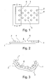
- the laminating film 1 in FIG. 1 consists of a substantially two-dimensional plastic film, which is intended to disguise an interior trim part for a motor vehicle to the user side and to a support member with the in FIG. 1 visible B-side to be laminated.
- a hotmelt is applied to the laminating film 1, in a plurality of diamonds 2 (numbered as an example).
- Each rhombus 2 has a height 3, with which it rises above a surface 4 of the B side 5 of the laminating film 1.
- the laminating film 1 is now laminated in a tool onto a carrier part 7 (cf. FIG. 3 ), the height 3 of the diamonds 2 from the hotmelt maintains the open connected property of the channel system 6. In the tool, the air can be removed laterally. It flows through the free cross sections of the channel system 6. In this case, the laminating film 1 moves step by step ever closer to the support part 7, until finally a direct fit occurs when the air is sucked out of the duct system 6.
- An embodiment of the invention already described provides for depressions to be introduced into the laminating film, for adhesive to be introduced into the depressions, and for the depressions of the laminating film to be flattened in a further step so that the adhesive passes to the surface of the laminating film.
- Such an example can be found in FIG. 4 shown:
- a laminating film 9 tapering in the machine direction 8 has embossed macroscopic depressions 10 (identified by way of example) which are filled with an adhesive 11 (numbered as an example).
- Each trough 10 receives a drop of adhesive 11.
- the laminating film 9 is guided through a station with two radiation heaters 14 (numbered as an example), which leads to heating of the laminating film 9.
- a memory effect in the plastic of the laminating film 9 causes the depressions 10 to recede in the area of the radiation heaters 14 and to become again flat with the surface 12 of the laminating film 9.
- the plastic of the laminating film 9 which resets in the memory effect, lifts the adhesive 11 out of the depressions 10, so that the adhesive ultimately protrudes from the film surface in droplets 15 and forms an open, interconnected channel system 16 (exemplarily numbered) between the droplets 15. forms.
- the film is heated prior to thermoforming.
- the embossed and filled with adhesive troughs back.
- the film becomes smooth again.
- the glue that was in the troughs becomes the excessive adhesive structure on the foil.
- the embossing roller 17 in the FIGS. 5 and 6 consists essentially of a conventional guide roller, wherein on a lateral surface 18 a plurality of macroscopically structured elevations 19 (numbered example) is arranged. Each individual elevation 19 can, for example, form a part-spherical body.
- a laminating film 20 runs through the plant in a machine direction 21, it is guided around the embossing roll 17 and assumes a multiplicity of hollows 22 (numbered as an example) (cf. FIGS. 7 and 8 ).
- the laminating film 20 provided with depressions 22 is guided along a slot die 23 at a minimum distance. From the slot die 23 occurs during the process of hot melt. Characterized in that the surface of the laminating film 20 between the wells 22 passes directly along the opening of the slot die 23, wherein in the ideal case no contact takes place, adhesive 24 exits only or at least predominantly in the wells 22.
- FIG. 9 A possible roller conveyor 25 for a system for laminating carrier parts with laminating films is shown in FIG. 9
- a laminating film 27 first enters a film store 28 with dancer rollers. After the film storage 28, the laminating film 27 continues to run and around a tempered embossing roll 29 by about 180 ° C.
- the embossing roller 29 transfers the laminating film 27 in the direction of travel directly to a pressure roller 30, which has on the film circulation side a slot die 31 for applying adhesive (not shown).
- a B-side 32 can therefore be fitted with troughs and adhesive, whereas an A-side 33 can remain untouched.
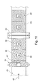
- the embodiment of the engraved roller 34 in the FIGS. 10a, 10b and 11 carries on its coat 35 a predominant area with a scar structure 36, which is preferably modeled on a natural leather.
- a scoring roller 34 can therefore produce individual scores 38, 39 (exemplified), each having a large grained area 40, but also a non-grained area 41 further in a machine direction 42, then the laminating film 43 passes through a station with a slot die 44, in which an adhesive application is made. This leads, with a suitable setting, to a larger, first area 45 on each individual end 38, 39 with adhesive applied, but also to a non-grained area 41 not provided with adhesive.
- Adhesive areas can be left out with this special design of the roller. Areas of application can be found for example in the adhesive savings in, for example, waste areas. In some door side panels, film sections are punched out after lamination. If there is no glue under these areas, then the punched blank can be more easily removed.
- the embossing roller may, for example, comprise a channel pattern.
- the photo 1 shows the remaining after heating and cooling drop structure of the adhesive application.
- the photo 2 shows an example of the adhesive structure after the release of the film from the component.
- the illustration 1 shows the remaining after heating and cooling drop structure of the adhesive application between the film and the component.
- the adhesive is a reactive or non-reactive thermoplastic hot melt adhesive, more preferably a hot melt adhesive based on ethylene vinyl acetates, polyacrylates, copolyamides, copolyesters, copolyethers, polyolefins, polyurethanes and corresponding co- and / or terpolymers.
- the components are interior components of vehicles.
- Such components consist in particular of materials based on natural fiber-reinforced polymer materials, for example a natural fiber, for example a flax polypropylene material, natural fiber, for example a (flax) PU or a natural fiber, for example (flax) epoxy resin material, and also a carrier produced by injection molding of polypropylene (PP), styrene-isoprene-styrene copolymer (ABS), polycarbonate-ABS (PCABS), polycarbonate (PC), thermoplastic polyurethane (TPU), thermoplastic polyolefin (TPO) or Polyamide comprises.
- PP polypropylene
- ABS styrene-isoprene-styrene copolymer
- PCABS polycarbonate-ABS
- PC polycarbonate
- TPU thermoplastic polyurethane
- TPO thermoplastic polyolefin
- Polyamide Polyamide
- the Figure 2 shows an example of an adhesive structure after the release of the film from the component.
- the bright shining channels which have allowed a uniform removal of the air between the component and the film have been completely preserved.
- Components with selected geometry and hole positioning have been shown to provide sufficient air transport within the adhesive grid over distances greater than 10 cm from the nearest hole, as well as over critical areas such as edges and radii.
- a plate-like component (240 mm diameter, 50 mm depth) made of polyoxymethylene (POM) without graining, with vacuum holes at a distance of about 2 cm in the outer edge region was laminated with the coated film to a single-station vacuum laminating the company KIEFEL (Germany), the bottom of the film being at 180 ° C, the top was heated to 140 ° C and the film was stretched in the longitudinal and transverse directions by 5%. Subsequently, the laminated component was inspected for imperfections due to air inclusions as well as the size of the laminated surface (for estimating the range of the air transport through the channels of the engraving).
- POM polyoxymethylene
Landscapes
- Engineering & Computer Science (AREA)
- Quality & Reliability (AREA)
- Manufacturing & Machinery (AREA)
- Chemical & Material Sciences (AREA)
- Organic Chemistry (AREA)
- Lining Or Joining Of Plastics Or The Like (AREA)
- Laminated Bodies (AREA)
- Physics & Mathematics (AREA)
- Fluid Mechanics (AREA)
Abstract
Die Erfindung betrifft ein Verfahren zum Versehen einer Kaschierfolie mit Klebstoff als vorbereitender Verfahrensschritt zum Herstellen eines kaschierten Formteils mittels eines Trägerteils, ein Verfahren zum Auftragen eines Hotmelts auf eine Kaschierfolie, ein Verfahren zum Herstellen eines kaschierten Formteils, die Verwendung eines Verfahrens, eine Anlage zum Kaschieren eines Trägerteils sowie ein Verfahren zum Umrüsten einer solchen Anlage. Die Erfindung hat erkannt, dass besonders hoch qualitative Kaschierungen erzeugt werden können, und dies selbst dann, wenn das Trägerteil, auf welches die Kaschierfolie aufkaschiert werden soll, nicht porös ist, wenn der Klebstoff zum Verbinden der Kaschierfolie mit dem Trägerteil makroskopisch strukturiert aufgetragen wird, so dass sich ein Kanalsystem ergibt. Durch das Kanalsystem kann die Luft zwischen der Kaschierfolie und dem Trägerteil während des Kaschierens abströmen.The invention relates to a method for providing a laminating film with adhesive as a preparatory method step for producing a laminated molding by means of a carrier part, a method for applying a hot melt to a laminating film, a method for producing a laminated molding, the use of a method, a laminating installation a support member and a method for retrofitting such a system. The invention has recognized that particularly high-quality laminations can be produced, and this even if the carrier part to which the laminating film is to be laminated is not porous, if the adhesive for connecting the laminating film to the carrier part is applied macroscopically structured, so that a channel system results. Through the channel system, the air between the laminating film and the support member during lamination flow.
Description
Die vorliegende Erfindung betrifft ein Verfahren zum Versehen einer Kaschierfolie mit Klebstoff, ein Verfahren zum Auftragen eines Hotmelts auf eine Kaschierfolie, die Verwendung eines solchen Verfahrens, eine Anlage zum Kaschieren eines Trägerteils mit einer Kaschierfolie sowie ein Verfahren zum Umrüsten einer Anlage.The present invention relates to a method for providing a laminating film with adhesive, a method for applying a hotmelt to a laminating film, the use of such a method, a system for laminating a carrier part with a laminating film and a method for retrofitting a plant.
Insbesondere betrifft die Erfindung ein Verfahren zum Kaschieren von Bauteilen mit Folien, wobei ein Klebstoff rasterförmig so auf die Oberfläche der Kaschierfolie und/oder des Bauteils aufgetragen wird, dass nach dem zusammenfügen der Folie und des Bauteils der Klebstoff zwischen der Folie und dem Bauteil angeordnet ist und die Bereiche zwischen den Klebstoffauftragungen ein Kanalsystem bilden, welches den gleichmäßigen Abtransport (Entfernen der Luft durch Abziehen und/oder Herauspressen) der zwischen dem Bauteil und der Folie befindlichen Luft gewährleistet.In particular, the invention relates to a method for laminating components with films, wherein an adhesive is applied in a grid pattern on the surface of the laminating film and / or the component, that after joining the film and the component of the adhesive between the film and the component is arranged and the areas between the adhesive applications form a channel system which ensures the uniform removal (removal of air by pulling and / or squeezing) of the air between the component and the film.
Weiterhin betrifft die Erfindung ein kaschiertes Formteil, welches durch das oben genannte Verfahren erhältlich ist sowie die Verwendung eines zwischen einem Bauteil und einer Kaschierfolie angeordneten Klebstoffrasters zur Reduzierung oder Vermeidung von Lufteinschlüssen bei der Kaschierung des Bauteils mit der Kaschierfolie.Furthermore, the invention relates to a laminated molding, which is obtainable by the above-mentioned method and the use of an arranged between a component and a laminating adhesive grid to reduce or avoid air pockets in the lamination of the component with the laminating film.
Die Kaschierung von Bauteilen mittels Anlegen eines Unterdruck bzw. Vakuums wie z.B. Vakuumkaschieren oder Varianten wie das In-Mould-Graining (IMG)-Verfahren und/oder mittels Pressdrucks sind in der Industrie weit verbreitet.The lamination of components by applying a vacuum or vacuum such. Vacuum laminating or variants such as the in-mold graining (IMG) process and / or pressing pressure are widely used in the industry.
Bei vakuumunterstützten Kaschiererfahren wird im Allgemeinen ein luftundurchlässiges bzw. begrenzt luftundurchlässiges Material (z.B. eine Dekorfolie) auf ein festes Bauteil kaschiert. Der verwendete Klebstoff kann dabei als Vorbeschichtung auf der Folie oder dem Bauteil aufgebracht sein.In vacuum assisted lapping, an air impermeable or limited air impermeable material (eg, a decorative film) is generally laminated to a solid component. The adhesive used can be used as a pre-coating on the film or be applied to the component.
Die Folie kann in diesem Prozess erwärmt und dann mittels Anlegen eines Unterdrucks auf das Bauteil aufgebracht werden. Die für die Folienverformung notwendige Wärmeenergie kann dabei auch zur Aktivierung des Klebstoffes genutzt werden. Eine entscheidende Bedingung für den Prozess ist die Luftdurchlässigkeit (Vakuumfähigkeit) des zu kaschierenden Substrates (Bauteils) in Kombination mit einer luftundurchlässigen Folie. Letzteres kann beispielsweise auch durch eine zusätzliche Membrane erreicht werden.The film can be heated in this process and then applied by applying a negative pressure to the component. The heat energy necessary for the film deformation can also be used to activate the adhesive. A crucial condition for the process is the air permeability (vacuum capability) of the substrate to be laminated (component) in combination with an air-impermeable film. The latter can be achieved for example by an additional membrane.
Während die Vakuumfähigkeit bei porösen Stoffen wie zum Beispiel Holzwerkstoffen oder offenporigen Verbundwerkstoffen in der Regel gegeben ist, sind bei luftundurchlässigen Bauteilmaterialien, wie sie typischerweise im Spritzgussverfahren hergestellt werden, oder begrenzt luftdurchlässigen Bauteilmaterialien, wie zum Beispiel bei bestimmten Faserverbundstoffen, besondere Vorkehrungen zu treffen. Hierzu zählen üblicherweise das Einbringen von Vakuumlöchern und das Aufbringen einer Kaschiernarbung auf das Bauteil, welche ein Absaugen der zwischen Folie und Bauteil befindlichen Luft ermöglicht. Durch die Kaschiernarbung entstehen Narbgräben im Bauteil über welchen die zwischen Bauteil und Folie befindliche Luft abgezogen werden kann.While the vacuum capability of porous materials, such as wood-based or open-cell composites, is generally met, special precautions must be taken in the case of air-impermeable component materials, such as typically made by injection molding or limited air-permeable component materials, such as certain fiber composites. These usually include the introduction of vacuum holes and the application of a Kaschiernarbung on the component, which allows suction of the air between the film and component. The Kaschiernarbung arise Narbgräben in the component through which the air located between the component and film can be removed.
Die Vakuumlöcher ermöglichen das Entweichen der Luft zwischen Folie und Bauteil durch Anlegen eines Unterdrucks bzw. Vakuums. Dies ist jedoch oft nicht ausreichend um klein- bis mittelgroße Lufteinschlüsse zu vermeiden. Diese können z.B. durch die Geometrie der Bauteile, aber auch durch den Ablegeprozess der Folie und die begrenzte Kapazität der Vakuumlöcher entstehen. Daher wird im Stand der Technik üblicherweise zusätzlich eine Kaschiernarbung auf das Bauteil aufgebracht, die auch nach dem "Erstkontakt" der Folie mit dem Bauteil einen weiteren Lufttransport durch die Gräben der Narbung zu den Löchern ermöglicht. Das Aufbringen dieser Kaschiernarbung auf das Bauteil ist jedoch technisch aufwändig und kostenintensiv, zumal eine ausreichende Narbung typischerweise 0,2 bis 0,3 mm Tiefe benötigt, was zu einem entsprechend höheren Materialeinsatz führt und auch das Gesamtgewicht des Bauteils erhöht. Dies kann bis zu 10 Gewichts-% des Bauteilgewichtes betreffen.The vacuum holes allow the escape of air between the film and the component by applying a negative pressure or vacuum. However, this is often not enough to avoid small to medium air pockets. These can be caused, for example, by the geometry of the components, but also by the deposition process of the film and the limited capacity of the vacuum holes. Therefore, in the prior art usually additionally a Kaschiernarbung is applied to the component, which allows for further air transport through the trenches of graining to the holes even after the "first contact" of the film with the component. However, the application of this Kaschiernarbung on the component is technically complex and costly, especially since a sufficient graining typically requires 0.2 to 0.3 mm depth, resulting in a correspondingly higher material usage and also increases the overall weight of the component. This can affect up to 10% by weight of the component weight.
Im Automobilbereich, insbesondere für Bauteile der Inneneinrichtung von Fahrzeugen, also für die hier bevorzugte Anwendung, kommen in der Praxis typischerweise zwei verschiedene Prozesse für die Folienkaschierung zum Einsatz.In the automotive sector, in particular for components of the interior of vehicles, so for the preferred application here, in practice, two different processes for film lamination are typically used.
In einem ersten Verfahren erfolgt der Klebstoffauftrag durch Sprühen auf das Bauteil. Hierbei muss ein lackartiger Klebstoffauftrag vermieden werden, da dieser zu einem Verstopfen der Vakuumlöcher durch den Klebstoff (z.B. bei Verwendung eines Dispersions- oder Lösemittelklebstoffs) führen kann.In a first method, the adhesive is applied by spraying onto the component. In this case, a paint-like adhesive application must be avoided, since this can lead to a clogging of the vacuum holes by the adhesive (for example, when using a dispersion or solvent adhesive).
In einem alternativen Verfahren erfolgt der Klebstoffauftrag (z.B. eines Schmelzklebstoffs) auf die Folie. Hierbei wird der Schmelzklebstoff mit der Folie auf die notwendige folientypische Verformtemperatur (je nach Folie 120 °C bis 210 °C) erwärmt und damit aktiviert.In an alternative method, adhesive application (e.g., a hot melt adhesive) to the film occurs. In this case, the hotmelt adhesive is heated with the film to the necessary film-typical deformation temperature (depending on the film 120 ° C to 210 ° C) and thus activated.
Bei letztgenanntem Prozess ist der Klebstoff (in der Regel ein reaktiver oder thermoplastischer Schmelzklebstoff) viskos-flüssig. Das gilt auch noch beim Vakuumfügeprozess. Der zähflüssige Klebstoff kann dabei aufgrund seiner Fließfähigkeit sehr leicht die Vakuumlöcher oder die Narbgräben verschließen. Dies verhindert den gleichmäßigen Abzug der Luft und kann somit die Bildung von Lufteinschlüssen begünstigen. Dies führt im fertigen kaschierten Formteil zu sichtbaren aber auch unsichtbaren Fehlstellen.In the latter process, the adhesive (usually a reactive or thermoplastic hot melt adhesive) is viscous-liquid. This also applies to the vacuum joining process. The viscous adhesive can very easily close the vacuum holes or the graves because of its flowability. This prevents the uniform extraction of air and can thus favor the formation of air pockets. This leads to visible but also invisible defects in the finished laminated molding.
Tatsächlich ist dem Fachmann bekannt, dass diese Art von Fehlstellen, die durch Lufteinschlüsse entstehen, bei der Verwendung von Schmelzklebstoffen häufig eintritt und die Ansprüche an die Narbqualität und Tiefe sowie Anzahl der Löcher höher sind als beim erstgenannten Prozess, in welchem der Klebstoff auf das Bauteil aufgesprüht wird.In fact, it is known to those skilled in the art that this type of imperfections caused by air pockets often occurs with the use of hot melt adhesives and the demands on the grain quality and depth and number of holes are higher than in the former process in which the adhesive is applied to the component is sprayed on.
Aufgabe der vorliegenden Erfindung ist es, dem Stand der Technik eine Alternative oder Verbesserung zur Verfügung zu stellen.The object of the present invention is to provide an alternative or improvement to the prior art.
Nach einem ersten Aspekt der vorliegenden Erfindung löst die gestellte Aufgabe ein Verfahren zum Versehen einer Kaschierfolie mit Klebstoff als vorbereitender Verfahrensschritt zum Herstellen eines kaschierten Formteils mittels eines Trägerteils, der Kaschierfolie und des Klebstoffs, wobei der Klebstoff die B-Seite der Kaschierfolie und eine Oberfläche des Trägerteils verbinden soll, mit den Schritten (a) Auftragen des Klebstoffs auf die B-Seite; und (b) anschließendes Umformen des Klebstoffs durch Prägen eines Rasters in den Klebstoff, so dass mit dem Raster Kanäle gebildet werden, bevor der Klebstoff mit der Oberfläche des Trägerteils verbunden wird.According to a first aspect of the present invention, the stated object solves a method for providing a laminating film with adhesive as a preparatory method step method of producing a laminated molding by means of a backing member, the liner and the adhesive, the adhesive to bond the B-side of the liner and a surface of the backing member, comprising the steps of: (a) applying the adhesive to the B-side; and (b) thereafter reshaping the adhesive by embossing a grid in the adhesive such that channels are formed with the grid before the adhesive is bonded to the surface of the support member.
Begrifflich sei hierzu folgendes erläutert:Conceptually, the following is explained:
Die "Kaschierfolie" kann eine Kunststofffolie sein, vorzugsweise eine Kunststofffolie auf Basis von Polyvinylchlorid (PVC), Polyolefinen, thermoplastischen Polyolefinen (TPO), Polycarbonat, Polyether, Polyestern, Polyurethanen, Poly(meth)acrylat, oder Kombinationen Co- und Terpolymeren derselben. Aber auch andere (Dekor-)Materialen sind geeignet wie zum Beispiel Schaumfolien, Textilien, Metallfolien, Echtleder, Kunstleder und Schichtverbundstoffe aus verschiedenen der oben genannten Materialien. Die Luftundurchlässigkeit kann hierbei durch den Einsatz von zusätzlichen Membrane erreicht werden.The "laminating film" may be a plastic film, preferably a plastic film based on polyvinyl chloride (PVC), polyolefins, thermoplastic polyolefins (TPO), polycarbonate, polyethers, polyesters, polyurethanes, poly (meth) acrylate, or combinations of copolymers and terpolymers thereof. But other (decorative) materials are suitable such as foam films, textiles, metal foils, real leather, artificial leather and laminates of various of the above materials. The airtightness can be achieved by the use of additional membrane.
Die Kaschierfolie weist bevorzugt eine Dicke im Bereich von 0,1 mm oder mehr und 7,0 mm oder weniger, vorzugsweise 1,0 mm oder mehr und 3,5 mm oder weniger, noch bevorzugter 1,5 mm oder mehr und 2,5 mm oder weniger auf.The laminating film preferably has a thickness in the range of 0.1 mm or more and 7.0 mm or less, preferably 1.0 mm or more and 3.5 mm or less, more preferably 1.5 mm or more and 2.5 mm or less.
Die Kunststofffolien umfassen insbesondere Folien auf Basis von Polyolefinen wie Polyethylen und Polypropylen. Weiterhin sind Folien auf Basis von Polyester, Polyamid, Polycarbonat, Polyvinylchlorid, Polymethylmethacrylat und Polystyrol bevorzugt. Unter Polyolefinen wie Polyethylen und Polypropylen werden hier nicht nur die betreffenden Ethylen- und Propylerihomopolymere, sondern auch Copolymere mit anderen Olefinen wie beispielsweise Acrylsäure oder 1-Olefinen verstanden. So sind unter Polyethylen insbesondere Ethylencopolymere mit 0,1 bis unter 50 Gew.-% eines oder mehrerer Olefine wie Propylen, 1-Buten, 1-Penten, 1-Hexen, 1-0cten, 1-Decen oder 1- Dodecen zu verstehen, wobei Propylen, 1-Buten und 1-Hexen bevorzugt sind. Unter Polypropylen sind insbesondere auch Propylencopolymere mit 0,1 bis unter 50 Gew.-% Ethylen und/oder eines oder mehrerer 1-Olefine wie 1- Buten, 1-Penten, 1-Hexen, 1-0cten, 1-Decen oder 1-Dodecen zu verstehen, wobei Ethylen, 1-Buten und 1-Hexen bevorzugt sind. Unter Polypropylen ist dabei bevorzugt im Wesentlichen isotaktisches Polypropylen zu verstehen.The plastic films in particular include films based on polyolefins such as polyethylene and polypropylene. Furthermore, films based on polyester, polyamide, polycarbonate, polyvinyl chloride, polymethyl methacrylate and polystyrene are preferred. Polyolefins such as polyethylene and polypropylene include not only the relevant ethylene and propylene homopolymers, but also copolymers with other olefins such as, for example, acrylic acid or 1-olefins. Thus, by polyethylene are meant in particular ethylene copolymers having from 0.1 to less than 50% by weight of one or more olefins such as propylene, 1-butene, 1-pentene, 1-hexene, 1-octene, 1-decene or 1-dodecene, wherein propylene, 1-butene and 1-hexene are preferred. In particular, polypropylene also includes propylene copolymers having from 0.1 to less than 50% by weight of ethylene and / or one or more 1-olefins, such as 1-butene, 1-pentene, 1-hexene, 1-octene, 1-decene or 1-hexene. Dodecene to understand, with ethylene, 1-butene and 1-hexene are preferred. Polypropylene is preferably to be understood as meaning essentially isotactic polypropylene.
Folien aus Polyethylen können aus HDPE oder LDPE oder LLDPE hergestellt werden.Polyethylene films can be made from HDPE or LDPE or LLDPE.
Unter Folien aus Polyamid sind solche bevorzugt, die sich von Nylon 6 ableiten.Among polyamide films, those derived from
Unter Folien aus Polyester sind solche aus Polybutylenterephthalat und insbesondere aus Polyethylenterephthalat (PET) bevorzugt.Among polyester films, those made of polybutylene terephthalate and especially polyethylene terephthalate (PET) are preferred.
Unter Folien aus Polycarbonaten sind solche bevorzugt, die sich von Polycarbonaten ableiten, die unter Verwendung von Bisphenol A hergestellt sind.Among polycarbonate films, preferred are those derived from polycarbonates prepared using bisphenol A.
Unter Folien aus Polyvinylchlorid sind solche aus Hart-Polyvinylchlorid oder Weich-Polyvinylchlorid zu verstehen, wobei Weich-Polyvinylchlorid auch Copolymere des Vinylchlorids mit Vinylacetat und/oder Acrylaten umfasst.Polyvinyl chloride films are understood as meaning those made of hard polyvinyl chloride or plasticized polyvinyl chloride, soft polyvinyl chloride also comprising copolymers of vinyl chloride with vinyl acetate and / or acrylates.
Kunststofffolien im Sinne der vorliegenden Erfindung können auch Verbundfolien umfassen; beispielsweise Folien, die eine der vorstehend genannten Folien und eine Metallfolie oder Faserfolien umfassen.Plastic films within the meaning of the present invention may also comprise composite films; For example, films comprising one of the aforementioned films and a metal foil or fiber sheets.
Als "Klebstoff" wird bevorzugt ein lösungsmittelfreier Schmelzklebstoff eingesetzt. Hierbei handelt es sich insbesondere um bei Raumtemperatur (21 °C +/-1 °C) feste, wasser- und lösungsmittelfreie Klebstoffe, welche auf die zu verklebenden Materialien aus der Schmelze aufgetragen werden und nach dem zusammenfügen beim Abkühlen unter Verfestigung physikalisch und/oder chemisch abbinden.As an "adhesive" is preferably a solvent-free hot melt adhesive used. These are in particular at room temperature (21 ° C +/- 1 ° C) solid, water and solvent-free adhesives, which are applied to the materials to be bonded from the melt and after joining together physically and / or on cooling to solidification chemically set.
Es eigenen sich aber auch Haftklebstoffe, Dispersionsklebstoffe, Lösungsmittelklebstoffe, zum Beispiel auf Basis von Polyurethan, Polyacrylat, Ethylenvinylacetat (EVA), Polyvinylacetat (PVAC), Styrol-lsopren-Styrol- Copolymer (SIS), Styrol-Butadien-Styrol-Copolymer (SBS) oder Chloropren-Kautschuk (CR).□Geeignete Schmelzklebstoffe können, je nach Anforderungen, insbesondere Schmelzklebstoffe in thermoplastischer oder reaktiver Qualität sein.But it is also suitable pressure-sensitive adhesives, dispersion adhesives, solvent adhesives, for example based on polyurethane, polyacrylate, ethylene vinyl acetate (EVA), Polyvinyl acetate (PVAC), styrene-isoprene-styrene copolymer (SIS), styrene-butadiene-styrene copolymer (SBS) or chloroprene rubber (CR) □ Suitable hot-melt adhesives can be made of thermoplastic or reactive hot melt adhesives, as required be.
Die eingesetzten Schmelzklebstoffe werden insbesondere in Abhängigkeit von den zu verklebenden Materialien und den diesbezüglichen jeweiligen Anforderungen, beispielsweise einer geforderten Temperatur- bzw. Hitzebeständigkeit der Verklebung etc., ausgewählt.The hot melt adhesives used are chosen in particular depending on the materials to be bonded and the respective respective requirements, for example a required temperature or heat resistance of the bond, etc.
Als thermoplastische Schmelzklebstoffe können insbesondere solche auf Basis von Ethylenvinylacetaten (EVA), Polyolefinen (z. B. amorphen Poly-alpha- olefinen oder Metallocen-katalytisch hergestellten Polyolefinen), Polyacrylaten, Copolyamiden, Copolyestern und/oder thermoplastischen Polyurethanen bzw. entsprechenden Co- und/oder Terpolymeren eingesetzt werden. Besonders bevorzugt sind dabei Metallocen-katalytisch hergestellte Polyolefine, da diese eine erhöhte Tackfreiheit besitzen.As thermoplastic hot melt adhesives, in particular those based on ethylene vinyl acetates (EVA), polyolefins (eg amorphous poly-alpha-olefins or metallocene-catalytically produced polyolefins), polyacrylates, copolyamides, copolyesters and / or thermoplastic polyurethanes or corresponding co- and / or terpolymers are used. Particularly preferred are metallocene-catalytically produced polyolefins, since these have an increased tack-free.
Als reaktive, beispielsweise feuchtigkeitsvernetzende Schmelzklebstoffe kommen insbesondere solche auf Basis von silangepfropften amorphen Poly- alpha-olefinen, silangepfropften Metallocen-katalytisch hergestellten Polyolefinen (vgl.
Polymere für im Rahmen der vorliegenden Erfindung geeignete, reaktive feuchtigkeitsvernetzende Schmelzklebstoffe sind beispielsweise die im Handel unter der Produktbezeichnung "Vestoplast® 206" von der Degussa AG, Marl, Deutschland, erhältlichen silanmodifizierten Poly-alpha-olefine. Erfindungs- gemäß besonders bevorzugt sind silanmodifizierte Poly-alpha-olefine mit zahlenmittleren Molekulargewichten Mn von 5.000 bis 25 .000 g/mol, vorzugsweise 10.000 bis 20.000 g/mol.Polymers for reactive moisture-crosslinking hot-melt adhesives suitable for the purposes of the present invention are, for example, those commercially available under the product name "Vestoplast® 206" from Degussa AG, Marl, Germany silane-modified poly-alpha-olefins. Particular preference according to the invention is given to silane-modified poly-alpha-olefins having number-average molecular weights Mn of 5,000 to 25,000 g / mol, preferably 10,000 to 20,000 g / mol.
Wie nachfolgend noch im Detail beschrieben, können zur Steuerung der offenen Zeit und/oder der Adhäsionseigenschaften reaktiven Schmelzklebstoffe Additive auf Basis nichtreaktiver Polymere, Harze und/oder Wachse zugesetzt sein, so z. B. gegebenenfalls hydrierte Kolophoniumharzester und aliphatische Kohlenwasserstoffharze.As described in more detail below, additives based on non-reactive polymers, resins and / or waxes may be added to control the open time and / or the adhesion properties of reactive hot melt adhesives. B. optionally hydrogenated rosin esters and aliphatic hydrocarbon resins.
Der Auftrag des Klebstoffs auf die Oberfläche der Folie und/oder das Bauteil, vorzugsweise ausschließlich auf der Oberfläche der Folie, erfolgt, wie zuvor beschrieben, in Temperaturbereichen von 90 °C oder mehr und 220 °C oder weniger, vorzugsweise 120 °C oder mehr und 190 °C oder weniger.The application of the adhesive to the surface of the film and / or the component, preferably exclusively on the surface of the film, as described above, in temperature ranges of 90 ° C or more and 220 ° C or less, preferably 120 ° C or more and 190 ° C or less.
Um eine gute Auftragbarkeit des Schmelzklebstoffs zu erreichen, werden üblicherweise solche Schmelzklebstoffe verwendet, welche bei den Verarbeitungstemperaturen, im Allgemeinen, 90 °C bis 200 °C, Brookfield- Viskositäten im Bereich von, im Allgemeinen, 50 bis 1.000.000 mPa·s aufweisen.In order to achieve good application of the hotmelt adhesive, usually those hotmelt adhesives are used which have Brookfield viscosities in the range of, in general, 50 to 1,000,000 mPa · s at the processing temperatures, generally 90 ° C to 200 ° C ,
Beispielsweise können in erfindungsgemäß bevorzugter Weise reaktive Schmelzklebstoffe auf Basis von silangepfropften Polyolefinen, insbesondere silangepfropften Poly-alpha-olefinen, eingesetzt werden, welche bei 180 °C Brookfield-Viskositäten im Bereich von 50 bis 50.000 mPa·s, insbesondere 1.000 bis 10.000 mPa·s, vorzugsweise 5.000 bis 8.000 mPa·s, besonders bevorzugt 5.500 bis 7.500 mPa·s, aufweisen.For example, reactive hot melt adhesives based on silane-grafted polyolefins, in particular silane-grafted poly-alpha-olefins, which at 180 ° C. have Brookfield viscosities in the range from 50 to 50,000 mPa · s, in particular from 1,000 to 10,000 mPa · s, can be used according to the invention , preferably 5,000 to 8,000 mPa · s, particularly preferably 5,500 to 7,500 mPa · s.
Zur Steuerung der Reaktivität und des Vernetzungsverhaltens können den reaktiven Schmelzklebstoffen üblicherweise die für diese Zwecke an sich gängigen Katalysatoren zugesetzt sein, so z. B. Dibutylzinndilaurat (DBTL), und dies in den für diese Zwecke an sich üblichen Mengen. Beispiele für erfindungsgemäß geeignete Katalysatoren sind die in der Klebstoffchemie gängigen und bekannten Katalysatoren, wie beispielsweise organische Zinnverbindungen, wie das zuvor genannte Dibutylzinndilaurat (DBTL) oder aber Alkylmercaptidverbindungen des Dibutylzinns, oder aber organische Eisen-, Blei-, Cobalt-, Wismut-, Antimon- und Zinkverbindungen sowie Mischungen der zuvor genannten Verbindungen oder Katalysatoren auf Aminbasis, wie tertiäre Amine, 1,4-Diazabicyclo[2.2.2]octan und Dimorpholinodiethylether sowie deren Mischungen. Erfindungsgemäß besonders bevorzugt ist Dibutylzinndilaurat (DBTL), insbesondere in Kombination mit Klebstoffen auf Basis der vorgenannten reaktiven, vorzugsweise silanmodifizierten Poly-alpha-olefine. Die eingesetzten Mengen an Katalysator(en) können in weiten Bereichen variieren; insbesondere beträgt die eingesetzte Katalysatormenge 0,01 bis 5 Gew.-%, bezogen auf den Klebstoff. Zur Steuerung der Anwendungseigenschaften der Klebstoffe können diesen außerdem weitere Additive zugesetzt sein, wie beispielsweise Weichmacher, hochsiedende organische Öle oder Ester oder andere der Plastifizierung dienende Additive, Stabilisatoren, Antioxidantien, Säurefänger, Füllstoffe, Alterungsschutzmittel und dergleichen.In order to control the reactivity and the crosslinking behavior, the reactive hotmelt adhesives may usually be admixed with the catalysts customary per se for these purposes, such as, for example, As dibutyltin dilaurate (DBTL), and this in the usual amounts for these purposes. Examples of catalysts which are suitable according to the invention are the catalysts known and known in adhesive chemistry, such as, for example, organic tin compounds, such as the abovementioned dibutyltin dilaurate (DBTL) or else Alkylmercaptidverbindungen of dibutyl tin, or organic iron, lead, cobalt, bismuth, antimony and zinc compounds and mixtures of the aforementioned compounds or amine-based catalysts such as tertiary amines, 1,4-diazabicyclo [2.2.2] octane and Dimorpholinodiethylether and mixtures thereof. Particularly preferred according to the invention is dibutyltin dilaurate (DBTL), in particular in combination with adhesives based on the abovementioned reactive, preferably silane-modified poly-alpha-olefins. The amounts of catalyst (s) used can vary within wide limits; In particular, the amount of catalyst used is 0.01 to 5 wt .-%, based on the adhesive. To control the application properties of the adhesives, these may also be added to other additives, such as plasticizers, high boiling organic oils or esters or other plasticizing additives, stabilizers, antioxidants, acid scavengers, fillers, anti-aging agents and the like.
Zur Steuerung der offenen Zeit und/oder der Adhäsionseigenschaften der zuvor genannten Klebstoffe, insbesondere auch im Hinblick auf eine verbesserte Handhabbarkeit, können den vorgenannten Schmelzklebstoffen außerdem weitere Additive auf Basis nichtreaktiver Polymere, Harze und/oder Wachse zugesetzt sein. Auf diese Weise lassen sich die Klebstoffeigenschaften anwendungsbezogen einstellen und sozusagen maßschneidern.To control the open time and / or the adhesion properties of the abovementioned adhesives, in particular also with regard to improved handleability, it is also possible to add further additives based on nonreactive polymers, resins and / or waxes to the abovementioned hotmelt adhesives. In this way, the adhesive properties can be adjusted application-related and tailor-made, so to speak.
Was die nichtreaktiven Polymere anbelangt, so können diese beispielsweise ausgewählt sein aus der Gruppe von (i) Ethylenvinylacetat-Copolymeren oder -Terpolymeren, insbesondere solchen mit Vinylacetat-Gehalten zwischen 12 und 40 Gew.-%, insbesondere 18 bis 28 Gew.-%, und/oder mit Schmelzindizes (MFls, DIN 53735) von 8 bis 800, insbesondere 150 bis 500; (ii) Polyolefinen, wie unmodifizierten amorphen Poly-alpha-olefinen, insbesondere mit zahlenmittleren Molekulargewichten Mn von 5.000 bis 25.000 g/mol, vorzugsweise 10.000 bis 20.000 g/mol, und/oder mit Erweichungsbereichen nach Ring und Kugel zwischen 80 °C und 170 °C, vorzugsweise zwischen 80 °C und 130 °C, oder unmodifizierten Metallocen- katalytisch hergestellten Polyolefinen (vgl.
Was die nichtreaktiven Harze anbelangt, so können diese insbesondere ausgewählt sein aus der Gruppe von Kohlenwasserstoffharzen, insbesondere aliphatischen, cyclischen oder cycloaliphatischen Kohlenwasserstoffharzen, gegebenenfalls modifizierten Kolophoniumharzen (z. B. Kolophoniumharzestern), Terpen-Phenolharzen, Cumaron-lndenharzen, Methylstyrol-Harzen, polymerisierten Tallharzestern und/oder Ketonaldehydharzen.As for the non-reactive resins, they may be selected from the group of hydrocarbon resins, especially aliphatic, cyclic or cycloaliphatic hydrocarbon resins, optionally modified rosin resins (eg, rosin esters), terpene phenolic resins, coumarone resins, methylstyrene resins Tallharzestern and / or Ketonaldehydharzen.
Was die nichtreaktiven Wachse anbelangt, so können beispielsweise Polyolefinwachse, wie Polyethylen- und Polypropylenwachse, oder auf dieser Basis modifizierte Wachse eingesetzt werden.As for the non-reactive waxes, for example, polyolefin waxes such as polyethylene and polypropylene waxes, or waxes modified on this basis can be used.
Bevorzugt besteht das zu kaschierende "Trägerteil" für das herzustellende "kaschierte Formteil" aus einem Material, das ausgewählt ist aus Materialien auf der Basis von naturfaserverstärkten Polymerwerkstoffen, beispielsweise ein Naturfaser-, beispielsweise ein Flachs-Polypropylen- Material, Naturfaser-, beispielsweise ein (Flachs)-PUR oder ein Naturfaser-, beispielsweise (Flachs)-Epoxidharz-Material, sowie auch ein im Spritzguss-Verfahren hergestellter Träger aus Polypropylen (PP), Styrol-Isopren-Styrol- Copolymer (ABS), Polycarbonat-ABS (PCABS), Polycarbonat (PC), thermoplastischem Polyurethan (TPU), thermoplastischem Polyolefin (TPO) oder Polyamid.Preferably, the "support member" to be laminated for the "laminated molding" to be produced consists of a material selected from materials based on natural fiber-reinforced polymer materials, for example a natural fiber, for example a flax polypropylene material, natural fiber, for example a ( Flax) -PUR or a natural fiber, for example (flax) epoxy resin material, as well as an injection-molded polypropylene support (PP), styrene-isoprene-styrene copolymer (ABS), polycarbonate-ABS (PCABS) , Polycarbonate (PC), thermoplastic polyurethane (TPU), thermoplastic polyolefin (TPO) or polyamide.
Besonders bevorzugt sind Materialien aus Kunststoff-Spritzguss, aus Acrylnitril-Butadienstyrol (ABS), Polycarbonat-ABS (PCABS), Polypropylen (PP), Polycarbonat (PC), thermoplastischem Polyolefin (TPO), Faserverbundwerkstoffe umfassend Naturfaser-PP, Glasfasern, Karbonfasern, Kunststofffasern, mineralischen Füllstoffen, Bindemittel- PP, Polyurethan, Phenolharz oder Kombinationen derselben.Particularly preferred are plastic injection molded materials, acrylonitrile butadiene styrene (ABS), polycarbonate ABS (PCABS), polypropylene (PP), polycarbonate (PC), thermoplastic polyolefin (TPO), fiber composites comprising natural fiber PP, glass fibers, carbon fibers, Plastic fibers, mineral fillers, binder PP, polyurethane, phenolic resin or combinations thereof.
Die Bauteile können eine Narbung aufweisen. Bevorzugt sind jedoch Bauteile ohne oder für den Abtransport von Luft ungeeignete Narbung (dies ist beispielsweise der Fall bei einer zu flachen Narbung).The components may have a grain. However, preferably components without or for the removal of air unsuitable graining (this is the case, for example a too flat graining).
Weiterhin sind die Bauteile vorzugsweise formstabil und/oder luftundurchlässig bzw. nur begrenzt luftdurchlässig bzw. vakuumdurchlässig.Furthermore, the components are preferably dimensionally stable and / or impermeable to air or only permeable to air or permeable to vacuum.
Im Rahmen der vorliegenden Erfindung wurden verschiedene Kaschierversuche auf glatten, ungenarbten Bauteilen mit einer im Automobilbereich üblicherweise eingesetzten TPO-Schaumfolie durchgeführt, wobei unterschiedliche Bauteilgeometrien, Klebstoffgravuren (auf der TPO-Folie), Kaschierparameter und sowie eine unterschiedliche Anzahl und Art von Bohrungen sowie Bohrungspositionen im Bauteil getestet wurden. Das Bauteilmaterial und der Klebstoff waren so ausgewählt, dass der Klebstoff nur begrenzte Adhäsion zu den Bauteilen aufbaut um ein Abziehen der kaschierten Folie und eine genaue Begutachtung der Klebfuge zu ermöglichen. Die Analyse der erfindungsgemäß kaschierten Bauteile zeigte eine perfekte Verklebung ohne Lufteinschlüsse.In the context of the present invention, various laminating tests were carried out on smooth, unhardened components with a TPO foam film commonly used in the automotive sector, with different component geometries, adhesive engravings (on the TPO film), laminating parameters and a different number and type of bores and bore positions in the Component were tested. The component material and the adhesive were selected so that the adhesive builds up only limited adhesion to the components to allow removal of the laminated film and an accurate assessment of the bondline. The analysis of the laminated components according to the invention showed a perfect bonding without air pockets.
Tatsächlich sind die durch den Gravurauftrag angelegten Kanäle auch im kaschierten Formteil noch erkennbar. Dadurch wird, zum Beispiel, die bei mit Luftfeuchtigkeit vernetzenden reaktiven Klebstoffen gefürchtete, unvollständige oder verlangsamte Vernetzung des Klebstoffs in Bereichen ohne Luftkontakt vermieden.In fact, the channels created by the engraving order are still recognizable even in the laminated molding. This avoids, for example, the incomplete or slowed crosslinking of the adhesive in areas without air contact, which are dreaded in the case of moisture-crosslinking reactive adhesives.
Im Allgemeinen wird das erfindungsgemäße Verfahren in der Form durchgeführt, dass das zusammenfügen von Kaschierfolie und Bauteil nach Beaufschlagung von Kaschierfolie und/oder des Bauteils mit dem Klebstoff durch Anlegen eines Unterdrucks (bzw. eines Vakuums) und/oder mittels Druck erfolgt. Die Verbindung mittels Druck geschieht beispielsweise durch Pressen der Folie auf das Bauteil oder Einpressen des Bauteils in die Folie, wobei die Folie in einer harten oder elastischen Aufnahme liegt, deren Form an das Bauteil angepasst ist.In general, the method according to the invention is carried out in the form that the laminating film and the component are joined together after application of laminating film and / or of the component with the adhesive by applying a negative pressure (or a vacuum) and / or by means of pressure. The connection by means of pressure, for example, by pressing the film on the component or pressing the component into the film, the film is in a hard or elastic recording, the shape of which is adapted to the component.
Der Klebstoffauftrag erfolgt bevorzugt auf einer Oberfläche der Kaschierfolie, die im nachfolgenden Schritt dem zu kaschierenden Substrat zugewandt sein wird. Die mit Klebstoff rasterförmig beschichtete Kaschierfolie kann sofort auf das Bauteil aufgelegt und anschließend aufkaschiert werden oder, alternativ, gelagert und später zur Kaschierung verwendet werden. Im letzteren Fall ist die mit Klebstoff vorbeschichtete Folie dann vorzugsweise lagerstabil. Dies bedeutet auch, dass sie als Rollenware bei Lagerung und Transport nicht verblockt und die Eigenschaften der Gravur bei Lagerung und Transport erhalten bleiben.The adhesive is preferably applied to a surface of the laminating film, which in the subsequent step will be facing the substrate to be laminated. The adhesive-grid-coated laminating film can be placed immediately on the component and then be laminated or, alternatively, stored and later used for lamination. In the latter case, the film precoated with adhesive is then preferably storage-stable. This also means that they are not locked as a roll product during storage and transport and preserve the properties of the engraving during storage and transport.
Die Verbindung mittels Vakuum erfolgt üblicherweise durch Anlegen eines Vakuums über den Rand des Bauteils oder über im Bauteil angeordnete Öffnungen, über welche ein Unterdruck angelegt werden kann (sogenannte Vakuumlöcher). Die Anzahl der Vakuumlöcher ist dabei der Größe und Geometrie des jeweiligen Bauteils sowie der verwendeten Klebstoffgravur/Klebstoffauftragung anzupassen. Vorzugsweise ist im Bauteil wenigstens ein Vakuumloch angeordnet. In weiteren erfindungsgemäßen Ausgestaltungen sind zwei, drei, vier oder noch mehr Öffnungen im Basisteil (also Substrat oder Trägerteil) angeordnet.The connection by means of vacuum is usually carried out by applying a vacuum over the edge of the component or via openings arranged in the component, via which a negative pressure can be applied (so-called vacuum holes). The number of vacuum holes must be adapted to the size and geometry of the respective component as well as the adhesive engraving / adhesive application used. Preferably, at least one vacuum hole is arranged in the component. In further embodiments according to the invention, two, three, four or even more openings are arranged in the base part (ie substrate or carrier part).
Bevorzugt erfolgt das Verbinden von Kaschierfolie und Bauteil unter Erwärmen, insbesondere oberhalb des Schmelz- oder Erweichungsbereiches des Klebstoffs.The bonding of the laminating film and the component preferably takes place with heating, in particular above the melting or softening range of the adhesive.
Gemäß einer besonders bevorzugten Ausführungsform wird dabei die Kaschierfolie zunächst mit einem geeigneten Schmelzklebstoff rasterförmig beaufschlagt und anschließend mit dem zu kaschierenden Bauteil zusammengefügt. Dabei wird der Schmelzklebstoff üblicherweise vor und/oder während des Zusammenfügens von Kaschierfolie und Bauteil oberhalb seiner Schmelz- bzw. Erweichungstemperatur erhitzt, so dass eine sichere Klebeverbindung zwischen Kaschierfolie einerseits und Bauteil andererseits gewährleistet ist.According to a particularly preferred embodiment, the laminating film is first applied in a grid-like manner with a suitable hotmelt adhesive and then joined together with the component to be laminated. In this case, the hotmelt adhesive is usually heated above and / or during the joining of the laminating film and the component above its melting or softening temperature, so that a secure adhesive bond between the laminating film on the one hand and the component on the other hand is ensured.
Zur Gewährleistung eines sicheren Verbunds zwischen der Kaschierfolie einerseits und dem Bauteil andererseits bei gleichzeitig guten Verarbeitungseigenschaften, wie optischen Eigenschaften etc., wird der Klebstoff bevorzugt in einer Menge von 10 g/m2 oder mehr und 200 g/m2 oder weniger, vorzugsweise 50 g/m2 oder mehr und 100 g/m2 oder weniger, eingesetzt bzw. aufgetragen.To ensure a secure bond between the laminating film on the one hand and the component on the other hand with good processing properties, such as optical properties, etc., the adhesive is preferably in an amount of 10 g / m 2 or more and 200 g / m 2 or less, preferably 50 g / m 2 or more and 100 g / m 2 or less, used or applied.
Der Klebstoff bedeckt nach dem Auftrag vorzugsweise 40 % oder mehr und 99 % oder weniger der mit dem Klebstoffraster versehenen Gesamtfläche der Folie und/oder des Bauteils, vorzugsweise der Folie, besonders bevorzugt 60 % oder mehr und 90 % oder weniger, ganz besonders bevorzugt 70 % oder mehr und 85 % oder weniger.The adhesive after application preferably covers 40% or more and 99% or less of the total surface area of the film and / or component, preferably the film, more preferably 60% or more and 90% or less, most preferably 70% % or more and 85% or less.
Der Auftrag des Klebstoffs kann unter Erwärmen, üblicherweise unter Aufschmelzen, bei Temperaturen im Bereich von 40 °C oder mehr und 220 °C oder weniger, insbesondere 120 °C oder mehr und 190 °C oder weniger erfolgen.The application of the adhesive may be carried out with heating, usually with melting, at temperatures in the range of 40 ° C or more and 220 ° C or less, in particular 120 ° C or more and 190 ° C or less.
In einer bevorzugten Ausgestaltung des erfindungsgemäßen Verfahrens erfolgt dieses unter Erhitzen der mit dem Klebstoff beschichteten Kaschierfolie vor und/oder während des Verbindens mit dem Bauteil. Alternativ kann auch das Bauteil erhitzt werden.In a preferred embodiment of the method according to the invention, this takes place by heating the laminating film coated with the adhesive before and / or during the connection to the component. Alternatively, the component can also be heated.
Die "B-Seite" ist diejenige Seite der Kaschierfolie, die dem Trägerteil zugewandt werden soll.The "B side" is the side of the laminating film that is to be facing the carrier part.
Entscheidend für den Erfindungsgedanken des ersten Aspekts der hier vorliegenden Erfindung ist jedoch die Reihenfolge dreier Schritte zueinander: Zunächst muss der Klebstoff auf die B-Seite der Folie aufgebracht werden. Danach muss der bereits aufgebrachte Klebstoff in einem separaten Schritt, also in Durchlaufrichtung durch die Maschine danach, unmittelbar oder mittelbar anschließend, umgeformt werden und dabei eine makroskopische Struktur eingebracht werden, also ein "Raster"; erst mit dem bereits umgeformten Klebstoff soll dann die Verbindung zwischen der Kaschierfolie und dem Trägerteil hergestellt werden.Decisive for the concept of the invention of the first aspect of the present invention, however, the order of three steps to each other: First, the adhesive must be applied to the B-side of the film. Thereafter, the already applied adhesive in a separate step, ie in the direction of passage through the machine thereafter, directly or indirectly subsequently, be transformed, and thereby introduced a macroscopic structure, ie a "grid"; only with the already formed adhesive is the connection between the laminating film and the carrier part to be made.
Während in der noch nicht veröffentlichten europäischen Patentanmeldung
Von Vorteil wird es durch das hier vorgestellte Verfahren möglich, bei geeigneter Gestaltung bestehende Anlagenkomponenten weiter zu verwenden, nämlich beispielsweise eine bereits vorhandene Einrichtung zum Auftragen von Klebstoff in herkömmlicher Weise.Advantageously, it is possible by the method presented here, with suitable design to continue to use existing plant components, namely, for example, an existing means for applying adhesive in a conventional manner.
Erst durch das zusätzlich vorgenommene Umformen entstehen die komplizierten Geometrien im Kunststoff und/oder im Klebstoff, welche als Kanäle während des Kaschiervorgangs dienen können.Only by the additional forming done the complicated geometries in the plastic and / or in the adhesive, which can serve as channels during the laminating process.
Eine bestehende Anlage wird dadurch kostengünstig und mit hoher Arbeitsqualität nachrüstbar.An existing system can be retrofitted cost-effectively and with high quality work.
Es sei ausdrücklich darauf hingewiesen, dass im Rahmen der hier vorliegenden Patentanmeldung unbestimmte Artikel und Zahlenangaben wie "ein", "zwei" usw. im Regelfall als mindestens-Angaben zu verstehen sein sollen, also als "mindestens ein...", "mindestens zwei..." usw., sofern sich nicht aus dem jeweiligen Kontext ausdrücklich, mittelbar oder technisch zwingend für den Fachmann ergibt, dass etwa dort nur "genau ein...", "genau zwei..." usw. gemeint sein soll oder kann.It should be expressly understood that in the context of the present patent application indefinite articles and numbers such as "a", "two", etc. should be understood as a rule as at least-information, so as "at least one ...", "at least two ... ", etc., unless it is clear from the context, expressly, indirectly or technically compelling for the expert that about there only" exactly one ... "," exactly two ... ", etc. should be meant or can.
Nach einem zweiten Aspekt der vorliegenden Erfindung löst die gestellte Aufgabe ein Verfahren zum Versehen einer Kaschierfolie mit Klebstoff als vorbereitender Verfahrensschritt zum Herstellen eines kaschierten Formteils mittels eines Trägerteils, der Kaschierfolie und des Klebstoffs, wobei der Klebstoff die B-Seite der Kaschierfolie und eine Oberfläche des Trägerteils verbinden soll, mit den Schritten (a) Einbringen von Vertiefungen in die B-Seite der Kaschierfolie, und (b) Einbringen des Klebstoffs in die Vertiefungen hinein und/oder zwischen den Vertiefungen, wobei die Reihenfolge dieser zwei Schritte auch umgedreht sein kann.According to a second aspect of the present invention, the stated object solves a method of providing a laminating film with adhesive as a preparatory step for producing a laminated molding by means of a support member, the laminating film and the adhesive, wherein the adhesive is the B-side of the laminating film and a surface of the Carrier part, with the steps of (a) introducing recesses in the B side of the laminating film, and (b) introducing the adhesive into the recesses and / or between the recesses, wherein the order of these two steps may also be reversed.
Begrifflich sei dazu erläutert, dass eine "Vertiefung" eine singuläre, vor allem eine Vielzahl von singulären, Mulde oder ein Kanal ist, wobei sich die Vertiefung gegenüber der Oberfläche auf der B-Seite der Kaschierfolie misst. Insbesondere kann als Referenzwert die Oberfläche an der B-Seite der Kaschierfolie verwendet werden, und zwar im Zulauf zu der Station beziehungsweise dem Werkzeug zum Einbringen der Vertiefungen. So ist es beispielsweise denkbar, dass die Folie auf der B-Seite glatt ist und dem Werkzeug zum Einbringen von Vertiefungen zuläuft. Beim Einbringen von Vertiefungen werden dann eine Vielzahl von Mulden oder Kanäle in die B-Seite eingedrückt, entweder über direkte, kontaktbehaftete mechanische Belastung oder über Über- oder Unterdruckaufbringung.Conceptually, it should be explained that a "depression" is a singular, especially a plurality of singular, trough or a channel, wherein the depression measures against the surface on the B side of the laminating foil. In particular, as a reference value the surface on the B side of the laminating film can be used, in the feed to the station or the tool for introducing the depressions. For example, it is conceivable that the film on the B side is smooth and tapers to the tool for introducing depressions. When depressions are introduced, a plurality of wells or channels are then forced into the B side, either via direct, mechanical contact, or via overpressure or underpressure.
Es kann einerseits vorteilhaft sein, den Klebstoff in die Vertiefung hinein einzubringen. Dafür spricht, dass die Kaschierfolie mit dem in den Vertiefungen befindlichen Klebstoff leichter weiter transportiert werden kann, ohne dass die Gefahr besteht, dass ein Übermaß an Klebstoff verläuft seitlich weggequetscht wird oder ähnliche nicht vorhersehbare Umlagerungen des Klebstoffs erfolgen. Andererseits spricht für ein Einbringen des Klebstoffs zwischen die Vertiefungen, dass dort das Auftragen in den meisten Fällen leichter sein wird und sogar mit herkömmlichen Werkzeugen durchgeführt werden kann. So kann beispielsweise eine herkömmliche Breitschlitzdüse verwendet werden, die im Stand der Technik einen vollflächigen, glatten Klebstoffauftrag auf eine Kaschierfolie aufbringt. Denn eine solche Breitschlitzdüse ist bereits aufgrund der bisherigen Erfahrungen des Bedienpersonals leicht so einstellbar, dass die in Maschinenrichtung durchlaufende Kaschierfolie in der Ebene ihrer zulaufenden Oberfläche mit Klebstoff versehen wird. In einem solchen Falle bliebe eine Vertiefung entweder frei von Klebstoff oder zumindest würde weniger Klebstoff aufgetragen.On the one hand, it may be advantageous to introduce the adhesive into the depression. This is supported by the fact that the laminating film can be transported more easily with the adhesive in the recesses, without the risk that an excess of adhesive will be squeezed out laterally or similar unpredictable rearrangements of the adhesive take place. On the other hand, for the introduction of the adhesive between the recesses, it is argued that, in most cases, the application will be easier and even be carried out with conventional tools. Thus, for example, a conventional slot die can be used, which in the prior art applies a full-surface, smooth application of adhesive to a laminating film. Because such a slot die is already easily adjustable due to the experience of the operator so far that the continuous in the machine direction laminating film is provided in the plane of its tapered surface with adhesive. In such a case, a recess would either be free of adhesive or at least less adhesive would be applied.
Ein Umdrehen der Schritte ist auch denkbar, so dass der Klebstoff zunächst aufgetragen wird und erst danach die Vertiefungen in der Kaschierfolie hergestellt werden. Der Auftrag des Klebstoffs kann dabei schon in makrostrukturierten Kanälen erfolgen, oder es kann eine Umverteilung des Klebstoffs beim Erzeugen der Vertiefungen erfolgen.Turning over the steps is also conceivable, so that the adhesive is applied first and only then are the recesses produced in the laminating film. The application of the adhesive can already take place in macrostructured channels, or it can be a redistribution of the adhesive when creating the wells.
Nach einem dritten Aspekt der vorliegenden Erfindung löst die gestellte Aufgabe ein Verfahren zum Versehen einer Kaschierfolie mit Klebstoff als vorbereitender Verfahrensschritt zum Herstellen eines kaschierten Formteils mittels eines Trägerteils, der Kaschierfolie und des Klebstoffs, wobei der Klebstoff die B-Seite der Kaschierfolie und eine Oberfläche des Trägerteils verbinden soll, mit den Schritten (a) Aufbringen des Klebstoffs durch eine Breitschlitzdüse, (b) wobei der Austritt des Klebstoffs durch die Breitschlitzdüse durch lokale Widerstände am Austritt gehindert und dadurch ein Raster geformt wird.According to a third aspect of the present invention, the stated object solves a method for providing a laminating film with adhesive as a preparatory method step for producing a laminated molding by means of a support member, the laminating film and the adhesive, wherein the adhesive is to join the B side of the liner and a surface of the carrier member, comprising the steps of (a) applying the adhesive through a slot die, (b) wherein the adhesive exiting through the die is localized at the exit prevented and thereby a grid is formed.
Dieser Aspekt der Erfindung ist wie folgt zu verstehen: An der Breitschlitzdüse zum Austreten des Klebstoffs liegt zulaufseitig ein zumindest im Wesentlichen uniformer Druck an. Die Breitschlitzdüse hat einen über die gesamte Länge des Schlitzes im Normalfall gleich breit bleibenden Austrittsschlitz. Es tritt also an jedem Punkt der Breitschlitzdüse Klebstoff mit der gleichen Geschwindigkeit und somit mit dem gleichen Durchsatz aus und wird dadurch auf der Kaschierfolie angeheftet.This aspect of the invention is to be understood as follows: At the slot die for exiting the adhesive, there is an at least substantially uniform pressure on the inlet side. The slot die has over the entire length of the slot normally the same width remaining exit slot. So it occurs at each point of the slot die adhesive at the same speed and thus with the same throughput and is thereby adhered to the laminating film.
Dies setzt jedoch voraus, dass der Austrittsströmung des Klebers über die gesamte Breite der Breitschlitzdüse ein einheitlicher Widerstand entgegengesetzt wird.However, this requires that the outlet flow of the adhesive over the entire width of the slot die is opposed to a uniform resistance.
Wird jedoch der Widerstand über die Breite der Breitschlitzdüse lokal geändert, so changiert auch der Volumenstrom des austretenden Klebstoffs.However, if the resistance across the width of the slot die changed locally, so also changes the volume flow of the exiting adhesive.
Wenn beispielsweise die Kaschierfolie lokal näher an der Breitschlitzdüse entlang transportiert oder weiter von ihr entfernt transportiert wird, und/oder wenn die Oberfläche der B-Seite der Kaschierfolie eine unterschiedliche Oberflächenspannung über die Breite der Breitschlitzdüse aufweist und/oder wenn beispielsweise lokal ein Gitter, ein Stab, eine Klappe oder ein anderer Austrittsquerschnittsveränderer vor den Breitschlitz bewegt und von diesem wieder weg entfernt wird, dann führt all dies zu einer rasterförmigen Auftragung von Klebstoff auf die Kaschierfolie.For example, if the laminating film is transported locally closer to or transported farther away from the sheet die, and / or if the surface of the B side of the laminating film has a different surface tension across the width of the slot die and / or if, for example, locally a grid Bar, a flap or other outlet cross section changer moved in front of the slot and away from this again, then all this leads to a grid-shaped application of adhesive to the laminating film.
Nach einem vierten Aspekt der vorliegenden Erfindung löst die gestellte Aufgabe ein Verfahren zum Auftragen eines Hotmelts auf eine Kaschierfolie und ein anschließendes Aufkaschieren auf ein Trägerteil, wobei der Hotmelt strukturiert aufgebracht wird. Unter rasterförmigem Klebstoffauftrag (Gravurauftrag) gemäß der vorliegenden Erfindung wird in der vorliegenden Offenbarung ein strukturierter Klebstoffauftrag, vor allem auf einer Oberfläche, verstanden, der zwischen den einzelnen Klebstoffauftragungen Kanäle bzw. ein Kanalsystem aufweist, welches vorzugsweise zusammenhängend ist. Der Klebstoff wird vorzugsweise in Form von Punkten und/oder Streifen in vorgegebenen Abständen (d.h. in einem bestimmten Raster) aufgetragen. Die dabei ausgebildeten Kanäle (bzw. das Kanalsystem) zwischen den Klebstoffkauftragungen ermöglichen nach dem zusammenfügen der Kaschierfolie und dem Bauteil ein optimiertes Absaugen bzw. Herauspressen, also Entfernen, der zwischen Folie und Bauteil befindlichen Luft. Das Absaugen der Luft erfolgt typischerweise über den Rand des Bauteils oder dadurch, dass über im Bauteil angeordnete Vakuumlöcher ein Unterdruck/Vakuum angelegt wird. Insbesondere ermöglichen die durchgehenden Kanäle (Kanalsystem) ein gleichmäßiges Entweichen der Luft durch Absaugen und/oder Herauspressen über die gesamte Oberfläche des mit Folie bedeckten Bauteils, wobei dies weitgehend unabhängig von der Geometrie des Bauteils (beispielsweise eventuell vorhandene Radien) geschieht. Auch bei der Folienkaschierung unter Anwendung von Druck ist die rasterförmige, das Kanalsystem bildende, Klebstoffauftragung gleichermaßen von Vorteil, da hier die zwischen dem Bauteil und der Folie befindliche Luft über die gesamte Oberfläche des Bauteils gleichmäßig herausgepresst werden kann.According to a fourth aspect of the present invention, the stated object solves a method for applying a hot melt to a laminating film and then laminating onto a carrier part, wherein the hotmelt is applied in a structured manner. Under raster-shaped adhesive application (gravure application) according to the present invention is in the present disclosure, a structured adhesive application, especially on a surface, understood between the individual adhesive applications channels or a channel system, which is preferably contiguous. The adhesive is preferably applied in the form of dots and / or stripes at predetermined intervals (ie in a specific grid). The thereby formed channels (or the channel system) between the Klebstoffkauftragungen allow for joining the laminating film and the component optimized suction or squeezing, so removing the air between the film and component. The suction of the air is typically carried out over the edge of the component or in that a negative pressure / vacuum is applied via vacuum holes arranged in the component. In particular, the continuous channels (channel system) allow a uniform escape of the air by suction and / or squeezing over the entire surface of the foil-covered component, this largely independent of the geometry of the component (for example, any radii present) happens. Also in the case of film lamination using pressure, the grid-shaped, the channel system forming, adhesive application is equally advantageous because here the air between the component and the film over the entire surface of the component can be evenly pressed out.
Überraschendweise wurde ferner gefunden, dass die rasterförmige, Kanäle ausbildende Struktur des Klebstoffauftrags während des Kaschierverfahrens ausreichend erhalten bleibt und kein Zerfließen des Klebstoffes stattfindet. Die Art des verwendeten Klebstoffs unterliegt dabei keiner besonderen Einschränkung, so dass hier grundsätzlich alle für die Folienkaschierung üblichen Kaschierklebstoffe eingesetzt werden können. Es wird insoweit auf den diesbezüglichen bekannten Stand der Technik verwiesen.Surprisingly, it has also been found that the grid-shaped, channel-forming structure of the adhesive application is sufficiently maintained during the laminating process and no bleeding of the adhesive takes place. The type of adhesive used is not subject to any particular restriction, so that in principle all laminating adhesives customary for film lamination can be used. Reference is made in this respect to the related prior art.
Weiterhin ermöglicht der rasterförmige Klebstoffauftrag, dass bei der Verwendung feuchtigkeitsreaktiver Klebstoffe über die Kanäle ausreichend Kontakt zur umgebenden Luft und damit zur Luftfeuchtigkeit besteht. Ein unvollständiges Vernetzen des Klebstoffes und somit die Bildung von Fehlstellen ohne Verklebung wird dadurch vermieden.Furthermore, the grid-like application of adhesive allows that when using moisture-reactive adhesives through the channels sufficient contact with the surrounding Air and thus to the humidity exists. An incomplete crosslinking of the adhesive and thus the formation of imperfections without sticking is thereby avoided.
Der rasterförmige Auftrag von Klebstoffen, insbesondere von Schmelzklebstoffen, ist dem Fachmann an sich bekannt. Typischerweise wird der rasterförmige Auftrag jedoch nur aus Gründen der Verringerung der Klebstoffmenge, dem besseren Verankern des Klebstoffes in offenen Substraten, wie z.B. Schäumen, dem Erstellen atmungsaktiver Laminate, z.B. bei der Kaschierung von atmungsaktiven Membranen bei denen ein geschlossener Klebstofffilm unerwünscht ist, eingesetzt. Die gezielte Verwendung in Kaschierverfahren unter Verwendung von Unterdruck oder Pressdruck und insbesondere zur Reduzierung und Vermeidung von Lufteinschlüssen, ist jedoch nicht bekannt.The grid-shaped application of adhesives, in particular hotmelt adhesives, is known per se to the person skilled in the art. Typically, however, the grid-shaped application will only be for reasons of reducing the amount of adhesive, better anchoring the adhesive in open substrates, such as e.g. Foaming, making breathable laminates, e.g. in the lamination of breathable membranes in which a closed adhesive film is undesirable used. However, the specific use in laminating using vacuum or pressing pressure and in particular to reduce and avoid air pockets, is not known.
Bei der gezielten Verwendung einer bestimmten Gravur, bei der der Klebstoff rasterförmig aufgetragen wird, bilden sich Bereiche, insbesondere linienförmige Bereiche ohne (oder mit deutlich geringerem) Klebstoffauftrag aus (sogenannte Kanäle), welche im Kaschierprozess hinreichend lange bestehen bleiben, so dass ein vollständiges und großflächiges, d.h. gleichmäßiges Entfernen der zwischen der Folie und dem Substrat befindlichen Luft durch Absaugen und/oder Herauspressen der Luft möglich wird.In the specific use of a specific engraving, in which the adhesive is applied in a grid, areas, in particular linear areas without (or with much less) adhesive application form (so-called channels), which remain sufficiently long in the laminating process, so that a complete and large-scale, ie uniform removal of the air between the film and the substrate by suction and / or squeezing the air is possible.
Vorzugsweise bleiben die Kanäle bis zum Ende des Kaschierprozesses und somit auch insbesondere im fertig kaschierten Formteil erhalten.Preferably, the channels remain until the end of the laminating process and thus in particular in the finished laminated molding.
Die Geometrie der Gravur bzw. des Rasters unterliegt dabei prinzipiell keinen Beschränkungen, soweit sichergestellt ist, dass ausreichend Kanäle gebildet werden, die ein Entfernen der Luft durch Absaugen und/oder Herauspressen bzw. bei feuchtigkeitsreaktiven Klebstoffen ausreichend Luftzugang (und damit Feuchtigkeitszutritt zum Klebstoff) ermöglichen.The geometry of the engraving or the grid is in principle subject to no restrictions, as far as it is ensured that sufficient channels are formed, which allow removal of the air by suction and / or squeezing or moisture-reactive adhesives sufficient air access (and thus moisture access to the adhesive) ,
Vorzugsweise wird der Klebstoff punktförmig oder streifenförmig aufgetragen, besonders bevorzugt in Form von pyramidenstumpfförmigen, mehreckigen (zum Beispiel drei, vier-, fünf-, sechs-, sieben-, acht-, neun- oder zehneckigen), rautenförmigen, rechteckigen, ovalen, L-förmigen, runden oder unregelmäßig geformten Klebstoffauftragungen, insbesondere in Form von pyramidenstumpfförmigen Klebstoffauftragungen.Preferably, the adhesive is applied in a punctiform or strip form, particularly preferably in the form of truncated pyramidal, polygonal (for example three, four-, five-, six-, seven-, eight-, nine- or ten-cornered), diamond-shaped, rectangular, oval, L-shaped, round or irregularly shaped adhesive applications, in particular in the form of truncated pyramid adhesive applications.
Weiterhin können auch Gravuren eingesetzt werden, welche dem Fachmann von den Standard-Narbgravuren der Bauteile her hinreichend bekannt sind.Furthermore, it is also possible to use engravings which are sufficiently familiar to the person skilled in the art from the standard engravings of the components.
Die Klebstoffauftragungen (insbesondere die pyramidenstumpfförmigen Klebstoffauftragungen) werden vorzugsweise in einem Abstand (gemessen an der Substratoberfläche) von 0,1 mm oder mehr und 10,0 mm oder weniger, vorzugsweise 0,3 mm oder mehr und 5,0 mm oder weniger, besonders bevorzugt 0,5 mm oder mehr und 4,0 mm, oder weniger, ganz besonders bevorzugt 1,0 mm oder mehr und 3,5 mm oder weniger, insbesondere 1,5 mm oder mehr und 2,5 mm oder weniger aufgetragen.The adhesive applications (in particular the truncated pyramidal adhesive applications) are preferably at a distance (measured at the substrate surface) of 0.1 mm or more and 10.0 mm or less, preferably 0.3 mm or more and 5.0 mm or less, especially preferably 0.5 mm or more and 4.0 mm or less, even more preferably 1.0 mm or more and 3.5 mm or less, in particular 1.5 mm or more and 2.5 mm or less.
Die Gravurtiefe, d.h. die Dicke (Höhe gemessen ab der jeweiligen Substratoberfläche) der Klebstoffauftragungen, liegt bevorzugt im Bereich von 0,1 mm oder mehr und 1,5 mm oder weniger, besonders bevorzugt 0,2 mm oder mehr und 1,0 mm oder weniger, ganz besonders bevorzugt 0,5 mm oder mehr und 0,8 mm oder weniger.The engraving depth, i. the thickness (height measured from the respective substrate surface) of the adhesive applications, is preferably in the range of 0.1 mm or more and 1.5 mm or less, more preferably 0.2 mm or more and 1.0 mm or less, very particularly preferably 0.5 mm or more and 0.8 mm or less.
Die Klebstoffpunkte werden dabei bevorzugt in unregelmäßiger Anordnung oder in unterschiedlichen Bereichen unterschiedlicher, vorzugsweise unregelmäßiger Anordnung aufgetragen, d.h. ohne Ausbildung von längeren geradlinigen Kanälen. Die Ausbildung einer Sekundärstruktur (d.h. einer Struktur, die erst durch eine bestimmte regelmäßige Anordnung der Klebstoffauftragungen erkennbar wird) wird somit vermieden, was dazu führt, dass der Betrachter des fertigen, kaschierten Bauteils den Anschein einer besonders glatten Oberfläche erhält. Selbstverständlich sind auch regelmäßige Klebstoffauftragungen in Form von geometrischen Mustern, deren Kombinationen oder Kombinationen davon mit unregelmäßigen Klebstoffauftragungen möglich. Auch kann die Klebstoffauftragung an das Formteil, dessen Gestalt und/oder dessen Oberfläche angepasst sein.The adhesive dots are preferably applied in an irregular arrangement or in different areas of different, preferably irregular arrangement, ie without the formation of longer rectilinear channels. The formation of a secondary structure (ie, a structure that becomes recognizable only by a certain regular arrangement of the adhesive application) is thus avoided, which leads to the observer of the finished, laminated component having the appearance of a particularly smooth surface. Of course, regular adhesive applications in the form of geometric patterns, their combinations or combinations thereof with irregular adhesive applications are possible. The adhesive application can also be adapted to the molded part, its shape and / or its surface.
Durch die durch das Klebstoffraster gestalteten/ausgebildeten Kanäle können insbesondere auch Bauteile ohne jegliche Narbung (oder solche mit flacher, typischerweise ungeeigneter Narbung, oder glatter Oberfläche) sowie Bauteile mit wenigen Löchern kaschiert werden. Hierdurch entsteht eine erheblich geringere Anzahl von Fehlstellen. Im bevorzugten Idealfall weist das Endprodukt keine erkennbaren Fehlstellen auf.In particular, components without any grain (or those with a flat, typically unsuitable graining or smooth surface) and components with few holes can also be laminated by the channels formed / formed by the adhesive grid. This results in a significantly lower number of defects. In the preferred ideal case, the final product has no detectable defects.
Wird der Klebstoff aufgeschmolzen (z.B. bei Verwendung von Schmelzklebstoffen), verläuft dieser nicht flächig, sondern es bilden sich beim Vorliegen einer geeigneten Gravur einzelne Tropfen, wobei die Kanäle zwischen den Tropfen erhalten bleiben. Diese Kanäle ermöglichen dann einen gleichmäßigen Lufttransport im Bereich zwischen dem Bauteil und der Kaschierfolie und damit die gewünschte horizontale Vakuumgängigkeit (horizontaler Lufttransport, d.h. Entfernung der Luft) innerhalb des Klebststoffrasters.If the adhesive is melted (for example, when using hot melt adhesives), this does not run flat, but it forms individual drops in the presence of a suitable engraving, the channels are retained between the drops. These channels then allow uniform air transport in the region between the component and the laminating film and thus the desired horizontal vacuum handling (horizontal air transport, i.e. removal of the air) within the adhesive matrix.
Bevorzugt wird der Hotmelt zu Kanalbildungserhebungen strukturiert aufgebracht, so dass sich zwischen den Kanalbildungserhebungen Kanäle bilden, durch welche Luft die Folienoberfläche entlang gesaugt werden kann, wobei bevorzugt ein Rautenmuster erzeugt wird.Preferably, the hotmelt is applied structured to channel formation surveys, so that form channels between the channel formation surveys, through which air the film surface can be sucked along, preferably a diamond pattern is generated.
Prinzipiell lässt sich aber die Erfindung sowohl mit einem Positivauftrag als auch mit einem Negativauftrag ausführen, also sowohl mit einem Auftrag des Klebstoffs als makrostrukturelle Erhebung, wobei sich zwischen der Vielzahl von makrostrukturellen Erhebungen die Kanäle ausbilden; oder als Kanäle, wobei anschließend durch eine Umformung erfolgt, welche die Kanäle erzeugt.In principle, however, the invention can be carried out both with a positive application and with a negative application, ie both with an application of the adhesive as a macrostructural elevation, whereby the channels form between the multiplicity of macrostructural elevations; or as channels, followed by a transformation which generates the channels.
Nach einem fünften Aspekt der vorliegenden Erfindung löst die gestellte Aufgabe ein Verfahren, vor allem unter Einbindung eines Verfahrens wie vorstehend beschrieben, zum Herstellen eines kaschierten Formteils mittels eines Trägerteils, einer Kaschierfolie und eines Klebstoffs, insbesondere eines Hotmelts, wobei der Klebstoff eine B-Seite der Kaschierfolie und eine Oberfläche des Trägerteils verbindet, mit den Schritten (a) rasterförmiges Auftragen des Klebstoffs auf die B-Seite der Kaschierfolie und/oder auf die Oberfläche des Trägerteils, wobei durch das rasterförmige Auftragen des Klebstoffs Kanäle ausgebildet werden, und zwar entweder bereits beim ersten Auftragen oder nach einem Umformen; (b) Zusammenfügen des Trägerteils und der Kaschierfolie so, dass die Schicht des rasterförmig aufgetragenen Klebstoffs zwischen der Kaschierfolie und dem Trägerteils angeordnet ist; und (c) Verbinden der Kaschierfolie mit dem Trägerteil durch (i) Abziehen der zwischen Trägerteil und Kaschierfolie befindlichen Luft über die Kanäle durch Anlegen eines Unterdrucks und/oder durch (ii) Herauspressen der zwischen Trägerteil und Kaschierfolie befindlichen Luft über die Kanäle durch Anlegen eines Pressdrucks, wobei sich das Verfahren dadurch kennzeichnet, dass die Kaschierfolie von einer Rolle als Endlosfolie abgezogen wird und/oder dass der Klebstoff während des Umlaufs der Kaschierfolie um eine Walze aufgetragen wird und/oder dass der Klebstoff mittels einer Breitschlitzdüse auf die Kaschierfolie aufgetragen wird und/oder dass der Klebstoff in eine Vertiefung hinein aufgetragen wird.According to a fifth aspect of the present invention, the stated object solves a method, especially involving a method as described above, for producing a laminated molding by means of a support member, a laminating film and an adhesive, in particular a hot melt, wherein the adhesive is a B-side the laminating film and a surface of the carrier part, with the steps (a) grid-like application of the adhesive on the B side of the laminating film and / or on the Surface of the support member, wherein channels are formed by the grid-shaped application of the adhesive, either already at the first application or after a forming; (b) assembling the carrier member and the liner so that the layer of adhesive applied in a grid pattern is disposed between the liner and the carrier member; and (c) bonding the liner to the carrier member by (i) drawing the air between the carrier and liner through the channels by applying a negative pressure and / or (ii) squeezing the air between the carrier and liner through the channels by applying a vacuum Pressing, wherein the method is characterized in that the laminating film is withdrawn from a roll as a continuous film and / or that the adhesive is applied during the circulation of the laminating film around a roller and / or that the adhesive is applied by means of a slot die on the laminating film and / or that the adhesive is applied in a recess.
Vorstehend wurden fünf voneinander unabhängige Aspekte der Erfindung im Detail erläutert.In the foregoing, five independent aspects of the invention have been explained in detail.
Es sei ausdrücklich darauf hingewiesen, dass sich die fünf vorstehend beschriebenen unabhängigen Erfindungsaspekte in beliebiger Form zu zweit, zu dritt, zu viert oder zu fünft miteinander kombinieren lassen.It is expressly understood that the five independent inventive aspects described above may be combined in any form with two, three, four, or five.
Dasselbe gilt ausdrücklich auch für alle Merkmale, die in Zusammenhang mit einer der unabhängigen Aspekte vorstehend beschrieben worden sind oder nachstehend beschrieben werden. All diese lassen sich auch auf jeden anderen der Aspekte der hier vorliegenden Erfindung anwenden.The same applies expressly to all features described above in connection with one of the independent aspects or described below. All of these can also be applied to any of the other aspects of the present invention.
Zur konstruktiven Ausführung wird vorgeschlagen, dass die Kaschierfolie um eine Prägewalze geführt wird, wobei die Oberfläche der Prägewalze strukturierte Erhebungen aufweist und damit ein Kanalmuster zu prägen eingerichtet ist.For structural design, it is proposed that the laminating film is guided around an embossing roller, wherein the surface of the embossing roller has structured elevations and is thus designed to emboss a channel pattern.
Die Zuführung der Kaschierfolie über Walzen ist sinnvoll, weil in den meisten bereits bestehenden Anlagen schon Walzenanordnungen zum Durchlauf für die Kaschierfolienbahn vorgesehen sind. In einer Walzenstrecke wird die Kaschierfolienbahn unter Zugkräften um die Walzen herumgeführt. Wenn eine Walze strukturierte Erhebungen in ihrer Oberfläche hat, was hier als eine "Prägewalze" bezeichnet wird, dann kann die Zugkraft darauf ausgelegt werden, vor allem in Kombination mit einer Beheizung der Prägewalze und/oder der Kaschierfolienbahn, dass bereits dadurch die strukturierte Auftragung möglich wird. So kann beispielsweise die Prägewalze in einen bereits vorher aufgebrachten vollflächigen Klebstofffilm kanalförmige Aussparungen einpressen; oder die Prägewalze kann in die Kaschierfolie Vertiefungen einpressen, vor allem bevor eine Beaufschlagung mit Klebstoff erfolgt.The feeding of the laminating film over rollers makes sense, because in most already existing systems are already provided roll arrangements for the passage for Kaschierfolienbahn. In a roll section, the laminating film web is guided around the rolls under tensile forces. If a roll has structured elevations in its surface, which is referred to herein as an "embossing roll", then the tensile force can be designed, especially in combination with heating of the embossing roll and / or the laminating film, thereby already allowing the structured application becomes. For example, the embossing roll can press channel-shaped recesses into an already applied full-surface adhesive film; or the embossing roll can press in recesses in the laminating film, especially before an adhesive is applied.
So ist es konkret denkbar, dass die Kaschierfolie um eine Prägewalze geführt wird, wobei die Oberfläche der Prägewalze strukturierte Erhebungen aufweist und damit eine Vielzahl von Vertiefungen in die Kaschierfolie einprägt, entweder als eine Vielzahl diskreter nicht verbundener Vertiefungen oder als eine Vielzahl von zu einem Kanalsystem verbundenen Vertiefungen.Thus, it is concretely conceivable that the laminating film is guided around an embossing roller, wherein the surface of the embossing roller has structured elevations and thus impresses a multiplicity of depressions in the laminating film, either as a multiplicity of discrete unconnected depressions or as a multiplicity of to a channel system associated wells.
Die Kaschierfolie kann während der Ausführung eines erfindungsgemäßen Verfahrens um eine Andrückwalze geführt werden, insbesondere nach einem Führen um eine Prägewalze, und während ihres Umlaufs um die Andrückwalze an einer Breitschlitzdüse entlang geführt werden.During the execution of a method according to the invention, the laminating film can be guided around a pressure roller, in particular after being guided around an embossing roller, and during its circulation around the pressure roller along a sheet die.
Während des Führens der Kaschierfolienbahn um eine Walze ist ihre Lage mit sehr hoher Präzision vorherbestimmbar. Dies ermöglicht es, eine Breitschlitzdüse auf eine exakt vorherbestimmbare Entfernung zur Kaschierfolienbahn einzustellen. Dadurch kann präzise wahlweise sowohl ein Einbringen des Klebstoffs in Vertiefungen bei gleichzeitigem Aussparen der nicht vertieften Bereiche als auch alternativ ein zumindest im Wesentlichen vollflächiges Versehen der nicht-vertieften Flächen mit Klebstoff bei gleichzeitigem Aussparen der Vertiefungen erreicht werden.During the guiding of the laminating film web around a roll, its position can be predicted with very high precision. This makes it possible to set a slot die to an exactly predeterminable distance from the laminating film web. As a result, either an introduction of the adhesive into recesses with simultaneous cutting out of the non-recessed regions as well as alternatively an at least substantially full-surface covering of the non-recessed surfaces with adhesive with simultaneous recessing of the recesses can be achieved precisely.
Außerdem ist es möglich, eine herkömmliche Breitschlitzdüse zu verwenden, wobei nur gegebenenfalls der Abstand zur vorbeilaufenden Kaschierfolienbahn verstellt wird. In die vorhandene Walzenstrecke wird entweder eine weitere Walze eingesetzt, nämlich die Prägewalze, oder eine Walze wird ausgetauscht.In addition, it is possible to use a conventional slot die, with only if necessary, the distance to the passing Kaschierfolienbahn is adjusted. In the existing roller track either another roller is used, namely the embossing roller, or a roller is replaced.
Es ist auch denkbar, dass der Klebstoff in in die Kaschierfolie eingebrachte makroskopische Vertiefungen eingebracht wird, bevorzugt oberflächenbündig mit der B-Seite der Kaschierfolie oder über einen flächigen Auftrag oberhalb der Vertiefungen miteinander verbunden.It is also conceivable that the adhesive is introduced into macroscopic depressions introduced into the laminating film, preferably connected to one another flush with the B side of the laminating film, or via a flat application above the depressions.
Ein Verfahren, welches die Eigenschaften geeigneter Kunststoffe mit Memory-Effekt besonders geschickt ausnutzt, sieht vor, dass Vertiefungen in der Kaschierfolie zunächst erzeugt, dann mit Klebstoff gefüllt und anschließend die Vertiefungen verflacht werden, so dass sich der Klebstoff aus den Vertiefungen erhebt und dadurch eine rasterförmige Struktur bildet.A method which makes particularly skillful use of the properties of suitable plastics with a memory effect provides that recesses are first produced in the laminating film, then filled with adhesive, and then the depressions are flattened so that the adhesive rises out of the recesses and, as a result forms grid-shaped structure.
Zum Verflachen der Vertiefungen wird die Kaschierfolie bevorzugt aktiv geheizt, vor allem mittels einer Anstrahlung mit zur Kaschierfolie ausgerichteten Wärmestrahlern.In order to flatten the depressions, the laminating film is preferably actively heated, in particular by means of irradiation with heat radiators aligned with the laminating film.
Eine Bestrahlung mit Wärme sorgt bei geeigneten Kunststoffen mit Memory-Effekt zu einer Rückstellung gegenüber der ursprünglich gegossenen und verstreckten Form. Wenn also zunächst mit einer Prägewalze im erwärmten Zustand, beispielsweise mit einer direkt erwärmten Prägewalze, Vertiefungen in das Kaschierfolienband hineingebracht werden, dann kann ein Rückstellen der Vertiefung hin zu der wieder flachen oder zumindest flacheren Folienbahn einfach durch Bestrahlung mit Wärme erreicht werden.Irradiation with heat, in the case of suitable plastics with a memory effect, provides for a return relative to the originally cast and stretched shape. Thus, if first indentations are introduced into the laminating film strip with an embossing roller in the heated state, for example with a directly heated embossing roller, then resetting the recess towards the again flat or at least flatter film web can be achieved simply by irradiation with heat.
Die Vertiefungen in der Kaschierfolie können über einen Memory-Effekt im Kunststoff ohne mechanische Einwirkung von außen verflacht werden. Alternativ können die Vertiefungen in der Kaschierfolie über eine mechanische Einwirkung von der A-Seite aus verflacht werden.The recesses in the laminating film can be flattened by a memory effect in the plastic without mechanical action from the outside. Alternatively, the recesses in the liner can be flattened by mechanical action from the A side.
Unter Umständen kann es erstrebenswert sein, mittels einer Prägewalze, vor allem einer Narbwalze, eine überwiegende Fläche eines Nutzens mit einer Oberflächenstruktur zu versehen, dabei aber einen Aussparbereich auszusparen, und im weiteren Verlauf den Nutzen mit Klebstoff zu versehen, dabei aber den Aussparbereich auszusparen, und zwar in einem designierten Abfallbereich und/oder in einem designierten Ausstanzbereich und/oder in einer Kaschierfolie für eine Türseitenverkleidung.Under certain circumstances, it may be desirable, by means of an embossing roller, especially a scoring roller, to have a predominant surface of a benefit with a surface structure provided, but to save a Aussparbereich, and in the further course to provide the benefit with adhesive, but to save the Ausspararbereich, in a designated waste area and / or in a designated punching and / or in a laminating film for a door side panel.
Solche Merkmale sind vor allem dann von großem Vorteil, wenn das Verfahren in einem Verfahren zum Herstellen eines kaschierten Formteils eingesetzt wird.Such features are especially of great advantage when the method is used in a method for producing a laminated molding.
Die besonders angestrebte Eignung eines Verfahrens wie vorstehend beschrieben findet sich in der Verwendung zum Herstellen eines Kraftfahrzeug-Innenverkleidungsteils. Nach einem siebten Aspekt der vorliegenden Erfindung löst die gestellte Aufgabe eine Anlage zum Kaschieren eines Trägerteils mit einer Kaschierfolie sowie mit einer Station zum Auftragen von Klebstoff zum Halten der Kaschierfolie auf dem Trägerteil, wobei die Anlage zum Durchführen eines Verfahrens wie vorstehend beschrieben eingerichtet ist.The particularly desirable suitability of a method as described above can be found in the use for producing a motor vehicle interior trim part. According to a seventh aspect of the present invention, the stated object solves a system for laminating a carrier part with a laminating film and with a station for applying adhesive for holding the laminating film on the support member, wherein the system for implementing a method is arranged as described above.
Als die "Station" ist ein Werkzeug aufzufassen, welches zum Auftragen des Klebstoffs eingerichtet ist, wobei diese Station zum Teil aus herkömmlichen Komponenten zusammengesetzt sein kann wie beispielsweise einer Breitschlitzdüse zum Auftragen von Klebstoff auf die in einer Walzenstrecke vorbeigeführt werdende Kaschierfolienbahn.As the "station" is to be understood a tool which is adapted to apply the adhesive, which station may be composed in part of conventional components, such as a slot die for applying adhesive to the laminating film web passing in a roll line.
In einer bevorzugten Ausführungsform der Erfindung sind in einer Maschinenrichtung, somit also in der designierten Durchlaufrichtung der Kaschierfolie durch die Anlage, zunächst eine Prägestation für die Kaschierfolie und erst später, unmittelbar oder mittelbar anschließend, die Station zum Auftragen von Klebstoff angeordnet sind.In a preferred embodiment of the invention, in one machine direction, ie thus in the designated direction of passage of the laminating film through the system, first an embossing station for the laminating film and only later, directly or indirectly, the station are arranged for applying adhesive.
Von besonderem Vorteil ist dies deshalb, weil beim Auftragen des Klebstoffs auf die Kaschierfolie mechanisch von der bereits geprägten Oberfläche der Kaschierfolie an ihrer B-Seite Gebrauch gemacht werden kann. So ist es beispielsweise denkbar, die geprägte B-Seite der Kaschierfolie zum lokalen Changieren des Austrittswiderstands einer an sich bekannten Breitschlitzdüse einzusetzen, so dass die geprägte Oberfläche an der B-Seite der Kaschierfolie zu einem makroskopisch strukturierten, gerasterten Klebstoffauftrag auf der Kaschierfolie führt. Dabei können die eingeprägten Vertiefungen und die dazwischen verbliebenen nicht vertieften Bereiche entweder positiv oder negativ das spätere Klebstoff- und somit Kanalbild vorgeben.This is particularly advantageous because, when the adhesive is applied to the laminating film, use can be made of the already embossed surface of the laminating film on its B side. Thus, it is conceivable, for example, to use the embossed B side of the laminating film for local oscillation of the exit resistance of a slot die known per se, so that the embossed surface on the B side the laminating film leads to a macroscopically structured, screened adhesive application on the laminating film. The embossed depressions and the non-recessed areas remaining therebetween can either predetermine the later adhesive and thus the channel image either positively or negatively.
Wenn die Prägestation eine Umlenkwalze mit einer rasterförmig strukturierten Oberfläche aufweist, dann kann der in der Walzenstrecke ohnehin herrschende Zug einfach dazu eingesetzt werden, die Prägung in die Oberfläche der B-Seite der Kaschierfolie und/oder des Klebstoffs einzuprägen.If the embossing station has a deflecting roller with a grid-like structured surface, then the tension prevailing in the roller track can simply be used to impress the embossing into the surface of the B side of the laminating film and / or of the adhesive.
Als die "rasterförmig strukturierte Oberfläche" sei - genau wie bei der Betrachtung der geprägten Kaschierfolie - eine Struktur betrachtet, welche makroskopisch zu einer Prägung führt. Produktionstechnisch notwendige oder aus Wirtschaftlichkeitsgründen nur tolerierte, mikroskopische Strukturierungen seien darunter nicht zu verstehen. Vielmehr muss die Struktur sowohl an der Prägewalze als auch in der Kaschierfolie und/oder zumindest im Klebstoff eine Kanalstruktur von einer solchen Größe, also Breite und Tiefe, erzeugen, dass die Kanäle in der eingangs beschriebenen Weise zum Leiten von Luft in Folge von Unterdruck oder Überdruck dienen können.As the "grid-shaped structured surface" - just as in the consideration of the embossed laminating film - is considered a structure which leads macroscopically to an embossing. Production-technically necessary or for economic reasons only tolerated, microscopic structuring are not to be understood thereby. Rather, the structure on both the embossing roll and in the laminating film and / or at least in the adhesive, a channel structure of such a size, ie width and depth, generate that the channels in the manner described above for conducting air as a result of negative pressure or Can serve overpressure.
Um mit möglichst geringer Kraftausübung das Prägen zu ermöglichen, wird vorgeschlagen, dass die Prägestation eine temperierte Walze aufweist.In order to enable embossing with the least possible exertion of force, it is proposed that the embossing station has a tempered roller.
Eine Walze ist dann "temperiert", wenn sie eine Ansteuerung, bevorzugt eine Regelung, zur Erhöhung der Temperatur gegenüber der Umgebungsluft aufweist. Insbesondere sei an eine elektrische Kontaktheizung, eine über Laserstrahlen arbeitende Heizung oder eine sonstige Strahlungsheizung gedacht. Die Heizung soll bevorzugt im Inneren der Walze angeordnet sein, so dass die Oberfläche der Walze, also derjenige Bereich, der mit der umlaufenden Kaschierfolie in Kontakt kommt, temperiert werden kann, ohne dass auf den Bahnlauf Einfluss genommen werden müsste.A roller is then "tempered" if it has an activation, preferably a regulation, for increasing the temperature with respect to the ambient air. In particular, it is intended to be an electrical contact heater, a heater operating via laser beams or another radiation heater. The heating should preferably be arranged in the interior of the roll, so that the surface of the roll, that is to say the region which comes into contact with the circulating laminating film, can be tempered without having to influence the web path.
Durch die Temperierung ist es bei geeigneter Einstellung der Anlage möglich, eine Prägung in die Kaschierfolie einzubringen, die bei erneuter Temperierung über den Memory-Effekt eines Kunststoffs zu einer Rückverformung der Kaschierfolie führt, wobei hier vorliegend das Rückverformen des Kunststoffs zu einer Umlagerung und Strukturgebung des Klebstoffs genutzt werden kann.By tempering it is possible with appropriate adjustment of the system to introduce an embossing in the laminating film, which leads to re-deformation of the laminating film on renewed tempering on the memory effect of a plastic, in this case the reverse deformation of the plastic to a rearrangement and structuring of the Adhesive can be used.
Die Station zum Auftragen von Klebstoff kann eine Breitschlitzdüse mit einer Klebstoffzuführung aufweisen.The adhesive application station may comprise a slot die with an adhesive feed.
Insbesondere sei an eine aus dem Stand der Technik bekannte Station zum Auftragen von Klebstoff gedacht, bei welcher eine Breitschlitzdüse der designierten Transportbahn der Kaschierfolie präzise zugestellt werden kann, so dass die Breitschlitzdüse dazu eingerichtet ist, eine gleichmäßige Klebstoffbeschichtung auf die vorbeilaufende Folie aufzutragen.In particular, it is intended to a known from the prior art station for applying adhesive in which a slot die of the designated transport path of the laminating foil can be precisely delivered, so that the slot die is adapted to apply a uniform adhesive coating on the passing film.
Mittels einer Modifikation der Folienbahn und/oder der Breitschlitzdüse kann diese Funktionalität für den hier erforderlichen lokal changierenden Klebstoffauftrag umfunktioniert werden.By means of a modification of the film web and / or the slot die, this functionality can be converted for the locally changing adhesive application required here.
Es sei ausdrücklich darauf hingewiesen, dass der Klebstoffauftrag und/oder ein Umformen des Klebstoffs nicht zwingend an einem rotatorischen Werkzeug und somit an der darum umlaufenden Folie erfolgen muss. Vielmehr kann es sich auch um eine stationäre Auftragung und/oder Umformung handeln, oder ein entsprechendes Werkzeug kann mit der Folie mitbewegt werden.It should be expressly pointed out that the adhesive application and / or reshaping of the adhesive does not necessarily have to take place on a rotary tool and thus on the film revolving around it. Rather, it can also be a stationary application and / or reshaping, or a corresponding tool can be moved with the film.
Für eine Breitschlitzdüse ist bevorzugt eine Abstandseinstellung zwischen einem Austritt der Breitschlitzdüse und einer designierten Bahn der Kaschierfolie vorgesehen.For a slot die, a spacing adjustment between an exit of the slot die and a designated path of the laminating film is preferably provided.
Dadurch kann auf einfache Weise die Menge des austretenden Klebstoffs variiert werden: Ist der Abstand größer, so tritt eine größere Menge Klebstoff aus; ist der Abstand hingegen geringer, so tritt eine geringere Menge an Klebstoff aus. Ist der Abstand null oder praktisch null, so wird nur ein sehr dünner Film an Klebstoff oder nicht einmal eine durchgehende Fläche von Klebstoff an den Bereichen austreten, die gerade von der vorbeilaufenden Folienbahn an der Breitschlitzdüse versperrt gehalten wird.As a result, the amount of the exiting adhesive can be varied in a simple manner: If the distance is greater, a larger amount of adhesive emerges; however, if the distance is less, a smaller amount of adhesive will leak out. Is the distance zero or virtually zero, so only a very thin film of adhesive or not even a continuous surface of adhesive will emerge at the areas just blocked by the passing sheet of film at the slot die.
Unabhängig davon kann das Zusammenspiel aus Austrittsdruck des Klebstoffs und Abstand zwischen der Düse und der Kaschierfolie auch dazu eingesetzt werden, nur nicht vertiefte Bereiche oder zumindest im Wesentlichen nur nicht vertiefte Bereiche mit dem Klebstoff flächig zu versehen, wobei der Klebstoff also entweder gar nicht oder zumindest im Wesentlichen nicht in die vertieften Bereiche hineingeht. Eine solche Beaufschlagung der Kaschierfolie mit Klebstoff hat sich bei jüngsten Prototypenversuchen des Erfinders als besonders leicht einstellbar erwiesen. Der Austritt des Klebstoffs aus der Düse kann dazu bevorzugt drucklos erfolgen.Regardless, the interaction of the outlet pressure of the adhesive and the distance between the nozzle and the laminating film can also be used to provide only non-recessed areas or at least substantially non-recessed areas with the adhesive surface, the adhesive so either not or at least essentially not entering the recessed areas. Such an exposure of the laminating film with adhesive has proved to be particularly easy to adjust in recent prototypes of the inventor. The exit of the adhesive from the nozzle can be done preferably without pressure.
Es wird vorgeschlagen, dass nach der Station zum Auftragen von Klebstoff und vor einer Aufbringstation der mit Klebstoff versehenen Kaschierfolie auf das Trägerteil eine Vertiefungsabflachstation angeordnet ist.It is proposed that after the station for application of adhesive and before an application station of the adhesive laminating film on the carrier part a recess flat station is arranged.
Die Vertiefungsabflachstation soll dazu eingerichtet sein, in die Kaschierfolie eingeprägte Vertiefungen abzuflachen, das heißt entweder vollständig zu eliminieren oder zumindest zum Teil, vor allem überwiegend, zu eliminieren. In einem einfachen Fall wird über einen mechanischen Angriff von der A-Seite oder der B-Seite der Kaschierfolie eine Rückstellung der geprägten Vertiefungen bewirkt, beispielsweise über eine Ansaugung der vertieften Oberfläche von der B-Seite aus oder über eine Drucklufteinwirkung gegen die vertiefte Stelle von der A-Seite aus die Rückstellung vorgenommen werden oder zumindest unterstützt werden.The depression flat station should be set up to flatten cavities embossed in the laminating film, that is to say either completely eliminate them or at least partly eliminate them, above all predominantly. In a simple case, a recovery of the embossed depressions is effected via a mechanical attack from the A side or the B side of the laminating film, for example via a suction of the recessed surface from the B side or via a compressed air action against the recessed position of A-side of the provision can be made or at least supported.
Bei ausreichender Wärme in der B-Seite der Kaschierfolie während des Einprägens der makroskopischen Struktur können Vertiefungen dergestalt eingebracht werden, dass die Tiefe der Vertiefungen auf der B-Seite geringer ist als eine etwaige Erhöhung auf der A-Seite.With sufficient heat in the B side of the liner during imprinting of the macroscopic structure, pits may be introduced such that the depth of the recesses on the B side is less than any increase on the A side.
Bevorzugt wird das Einbringen von Vertiefungen auf der B-Seite jedoch so vorgenommen, dass sich auf der A-Seite keine Erhöhungen ergeben. Dazu kann beispielsweise dem die Vertiefung einprägenden Werkzeug gegenübergestellt eine Halteeinrichtung vorgesehen sein, beispielsweise eine glattflächige Andrückwalze.Preferably, however, the introduction of depressions on the B side is made so that there are no elevations on the A side. For this purpose, for example, a retaining device can be provided opposite the tool which impresses the recess, for example a smooth-surface pressure roller.
Nach einem weiteren Aspekt der Erfindung löst die gestellte Aufgabe ein Verfahren zum Umrüsten einer Anlage mit einer Breitschlitzdüse zum Auftragen von Klebstoff auf eine entlanglaufende Kaschierfolie zum Herstellen eines kaschierten Formteils, mit dem folgenden Schritt: Einsetzen einer Einrichtung zum Herstellen eines rasterförmigen Strukturmusters an einer B-Seite der Kaschierfolie, und zwar auf dem Weg vom Einbringen der Kaschierfolie hin zur Breitschlitzdüse.According to a further aspect of the invention, the stated object solves a method for converting a system with a slot die for applying adhesive to a running laminating film for producing a laminated molding, comprising the following step: inserting a device for producing a grid-shaped pattern structure on a B Side of the laminating film, and on the way from the introduction of the laminating film to the slot die.
Es versteht sich, dass eine bestehende Anlage unter Verwendung der hier vorgestellten Erfindung leicht umgerüstet werden kann: Die vorhandene Walzenstrecke kann ebenso weiterhin benutzt werden wie eine bereits vorhandene Breitschlitzdüse zum Auftragen von Klebstoff. Es muss lediglich irgendwo in der Anlage, nach dem Einspeisen der Kaschierfolie in die Anlage und vor dem Klebstoffauftrag, aber auch jenseits des Klebstoffauftrags, die Einrichtung zum Herstellen der rasterförmigen Struktur an der Kaschierfolie installiert werden, beispielsweise durch Austausch eines bestehenden Bauteils wie vor allem einer Umlenkwalze.It is understood that an existing plant can be easily converted using the invention presented here: The existing roll section can continue to be used as an existing slot die for applying adhesive. It only has to be installed anywhere in the system, after feeding the laminating film into the system and before the adhesive application, but also beyond the adhesive application, the means for producing the grid-like structure of the laminating film, for example by replacing an existing component such as one deflecting.
Die vorliegende Erfindung betrifft nach weiteren Aspekten, die alternativ oder kumulativ zum Vorstehend Beschriebenen und/oder alternativ oder kumulativ zu den Patentansprüchen dieser Patentanmeldung auftreten können, folgende Punkte:
- 1. Ein Verfahren zur Herstellung eines kaschierten Formteils aus einem Bauteil (alternativ auch als Substrat bezeichnet) und einer Kaschierfolie (alternativ auch als Folie bezeichnet) welches dadurch gekennzeichnet ist, dass es folgende Schritte umfasst:
- rasterförmiges Auftragen eines Klebstoffs auf die Oberfläche der Kaschierfolie und/oder des Bauteils, wobei durch das rasterförmige Auftragen des Klebstoffs auf der Oberfläche Kanäle ausgebildet werden,
- zusammenfügen des Bauteils und der Kaschierfolie so, dass die Schicht des rasterförmig aufgetragenen Klebstoffs zwischen der Kaschierfolie und dem Bauteil angeordnet ist, und
- Verbinden der Kaschierfolie mit dem Bauteil durch (a) Abziehen der zwischen Bauteil und Folie befindlichen Luft über die Kanäle durch Anlegen eines Unterdrucks oder (b) Herauspressen der zwischen Bauteil und Folie befindlichen Luft über die Kanäle durch Anlegen eines Pressdrucks, oder (c) eine Kombination aus (a) und (b).
- 2. Ein
Verfahren gemäß Punkt 1, dadurch gekennzeichnet, dass das Verbinden der Kaschierfolie mit dem Bauteil durch Abziehen der zwischen Bauteil und Folie befindlichen Luft über die Kanäle mittels Anlegen eines Unterdrucks erfolgt. - 3. Ein Verfahren gemäß einem der Punkte 1
oder 2, dadurch gekennzeichnet, dass in dem Bauteil mindestens ein Vakuumloch angeordnet ist, über das der Unterdruck angelegt wird. - 4. Ein Verfahren gemäß einem oder mehreren der Punkte 1 bis 3, dadurch gekennzeichnet, dass der Klebstoff punktförmig oder streifenförmig 15 aufgetragen wird, vorzugsweise in Form von pyramidenstumpfförmigen, mehreckigen, rautenförmigen, rechteckigen, ovalen, L-förmigen, runden oder unregelmäßig geformten Klebstoffauftragungen, besonders bevorzugt in Form von pyramidenstumpfförmigen oder kegelstumpfförmigen Klebstoffauftragungen.
- 5. Ein Verfahren gemäß einem oder mehreren der Punkte 1
bis 4, dadurch gekennzeichnet, dass die Kanäle zwischen den Bereichen/Stellen der Klebstoffauftragung während des rasterförmigen Auftragens frei von Klebstoff bleiben. - 6. Ein Verfahren gemäß einem oder mehreren der Punkte 1
bis 5, dadurch gekennzeichnet, dass die Kanäle bis zum Ende des Kaschierprozesses erhalten bleiben. - 7. Ein Verfahren gemäß einem oder mehreren der Punkte 1
bis 6, dadurch gekennzeichnet, dass der Klebstoff in unregelmäßiger Anordnung oder Bereichen unregelmäßiger Anordnung aufgetragen wird. - 8. Ein Verfahren gemäß einem oder mehreren der Punkte 1
bis 7, dadurch gekennzeichnet, dass die Klebstoffauftragungen ineinem Abstand von 0,1 mm odermehr und 10,0 mm oder weniger, vorzugsweise 0,3 mm oder mehr und 5,0 mm oder weniger, besonders bevorzugt 0,5 mm oder mehr und 4,0 mm oder weniger, ganz besonders bevorzugt 1,0 mm oder mehr und 3,5 mm oder weniger, insbesondere 1,5 mm oder mehr und 2,5 mm oder weniger angeordnet werden. - 9. Ein Verfahren gemäß einem oder mehreren der Punkte 1
bis 8, dadurch gekennzeichnet, dass der Klebstoff ein reaktiver oder nicht-reaktiver 10 thermoplastischer Schmelzkleber ist, bevorzugt ein Schmelzkleber auf Basis von Ethylenvinylacetaten, Polyacrylaten, Copolyamiden, Copolyestern, Copolyethern, Polyolefinen, Polyurethanen und entsprechenden Co- und/oder Terpolymeren. - 10. Ein Verfahren gemäß einem oder mehreren der Punkte 1
bis 9, dadurch gekennzeichnet, dass der Klebstoff ein latent reaktives, zwei- oder mehrkomponentiges System ist, bei dem die Reaktionskomponenten als homogene Mischung oder als Rasterpunkte nebeneinander oder übereinander aufgetragen werden. - 11. Ein Verfahren gemäß einem oder mehreren der Punkte 1
bis 10, dadurch gekennzeichnet, dass die Kaschierfolie eine Kunststofffolie ist, vorzugsweise eine Kunststofffolie auf Basis von Polyvinylchlorid (PVC), Polyolefinen, thermoplastischen Polyolefinen (TPO), Polycarbonat, Polyether, Polyestern, Polyurethanen, Poly(meth)acrylat, oder Kombinationen, Co- oder Terpolymeren derselben. - 12. Verfahren gemäß einem oder mehreren der Punkte 1
bis 11, dadurch gekennzeichnet, dass die Kaschierfolie eine Dickeim Bereich von 0,1 mm oder mehr und 7,0 mm oder weniger, vorzugsweise 1,0 mm oder mehr und 3,5 mm oder weniger,noch bevorzugter - 13. Ein Verfahren gemäß einem oder mehreren der Punkte 1
bis 12, dadurch gekennzeichnet, dass das Bauteil aus einem luftundurchlässigen oder begrenzt luftdurchlässigen Material besteht. - 14. Ein Verfahren gemäß einem oder mehreren der Punkte 1
bis 13, dadurch gekennzeichnet, dass das Bauteil formstabil ist. - 15. Ein Verfahren gemäß einem oder mehreren der Punkte 1
bis 14, dadurch gekennzeichnet, dass das Bauteil aus einem Material besteht, das ausgewählt ist aus Kunststoff-Spritzguss aus Acrylnitril-Butadienstyrol (ABS), Polycarbonat-ABS (PCABS), Polypropylen (PP), Polycarbonat (PC), thermoplastischem Polyolefin (TPO), Faserverbundwerkstoffe umfassend Naturfaser-PP, Glasfasern, Carbonfasern, Kunststofffasern, mineralischen Füllstoffen, Bindemittel-PP, Polyurethan, Phenolharz oder Kombinationen derselben. - 16. Ein Verfahren gemäß einem oder mehreren der Punkte 1
bis 15, dadurch gekennzeichnet, dass das Bauteil keine Kaschiernarbung aufweist. - 17. Ein Verfahren gemäß einem oder mehreren der Punkte 1
bis 16, dadurch gekennzeichnet, dass die mit Klebstoff beschichtete Kaschierfolie vor und/oder während des Verbindens mit dem Bauteil erhitzt wird. - 18. Ein Verfahren gemäß einem oder mehreren der Punkte 1
bis 17, dadurch gekennzeichnet, dass das kaschierte Formteil eine Fahrzeuginnenverkleidung oder ein Teil einer Fahrzeuginnenverkleidung ist. - 19. Ein kaschiertes Formteil, insbesondere eine Fahrzeuginnenverkleidung oder ein Teil einer Fahrzeuginnenverkleidung, hergestellt nach einem Verfahren gemäß einem oder mehreren der vorangehenden Punkte.
- 20. Die Verwendung eines zwischen einem Bauteil und einer Kaschierfolie angeordneten Klebstoffrasters zur Reduzierung oder Vermeidung von Lufteinschlüssen bei der Kaschierung des Bauteils mit der Kaschierfolie.
- 21. Die
Verwendung gemäß Punkt 20 , dadurch gekennzeichnet, dass- der Klebstoff auf die Oberfläche der Kaschierfolie und/oder des Bauteils rasterförmig aufgetragen wird, wobei durch das rasterförmige Auftragen des Klebstoffs auf der Oberfläche Kanäle ausgebildet werden,
- das Bauteils und die Kaschierfolie so zusammengefügt werden, dass die Schicht des rasterförmig aufgetragenen Klebstoffs zwischen der Kaschierfolie und dem Bauteil angeordnet ist, und
- die Kaschierfolie mit dem Bauteil durch (a) Abziehen der zwischen Bauteil
(a) und (b) verbunden (kaschiert) wird. - 22. Die Verwendung gemäß einem der Punkte 20
oder 21, dadurch gekennzeichnet, dass der Klebstoff punktförmig oder streifenförmig auf die Kaschierfolie aufgetragen wird, vorzugsweise in Form von rechteckigen, mehreckigen, rautenförmigen, runden oder unregelmäßig geformten Klebstoffauftragungen, besonders bevorzugt in Form von pyramidenstumpfförmigen oder kegelstumpfförmigen Klebstoffauftragungen. - 23. Die Verwendung gemäß einem oder mehreren der Punkte 20
bis 22, dadurch gekennzeichnet, dass die Kaschierung eine Vakuumkaschierung, ein In-Mould-Grain (IMG)-Verfahren, eine Presskaschierung oder Mischformen derselben umfasst. - 24. Verwendung des kaschierten Formteils nach Punkt 19 als Fahrzeuginnenverkleidung oder als Teil einer Fahrzeuginnenverkleidung.
- 1. A method for producing a laminated molding from a component (alternatively referred to as substrate) and a laminating film (alternatively referred to as a film) which is characterized in that it comprises the following steps:
- grid-shaped application of an adhesive to the surface of the laminating film and / or the component, wherein the grid-shaped application of the adhesive on the surface Channels are formed
- joining the component and the laminating film so that the layer of the grid-shaped adhesive applied between the laminating film and the component is arranged, and
- Connecting the laminating film to the component by (a) drawing off the air between the component and the film via the channels by applying a negative pressure or (b) pressing out the air between the component and the film via the channels by applying a pressing pressure, or (c) a Combination of (a) and (b).
- 2. A method according to
item 1, characterized in that the bonding of the laminating film to the component takes place by removing the air between the component and the film via the channels by means of applying a negative pressure. - 3. A method according to one of the
items - 4. A method according to one or more of the
items 1 to 3, characterized in that the adhesive is applied in a punctiform orstrip 15, preferably in the form of truncated pyramidal, polygonal, diamond-shaped, rectangular, oval, L-shaped, round or irregularly shaped adhesive applications , particularly preferably in the form of truncated pyramidal or frusto-conical adhesive applications. - 5. A method according to one or more of the
items 1 to 4, characterized in that the channels between the areas / points of adhesive application during the grid-like application remain free of adhesive. - 6. A method according to one or more of the
items 1 to 5, characterized in that the channels are retained until the end of the laminating process. - 7. A method according to one or more of the
items 1 to 6, characterized in that the adhesive is applied in an irregular arrangement or areas of irregular arrangement. - 8. A method according to one or more of the
items 1 to 7, characterized in that the adhesive applications at a distance of 0.1 mm or more and 10.0 mm or less, preferably 0.3 mm or more and 5.0 mm or less, more preferably 0.5 mm or more and 4.0 mm or less, even more preferably 1.0 mm or more and 3.5 mm or less, especially 1.5 mm or more and 2.5 mm or less to be ordered. - 9. A method according to one or more of the
items 1 to 8, characterized in that the adhesive is a reactive or non-reactive thermoplastic hot melt adhesive, preferably a hot melt adhesive based on ethylene vinyl acetates, polyacrylates, copolyamides, copolyesters, copolyethers, polyolefins, polyurethanes and corresponding co- and / or terpolymers. - 10. A method according to one or more of the
items 1 to 9, characterized in that the adhesive is a latently reactive, two- or multi-component system in which the reaction components are applied as a homogeneous mixture or as screen dots next to each other or one above the other. - 11. A method according to one or more of the
items 1 to 10, characterized in that the laminating film is a plastic film, preferably a plastic film based on polyvinyl chloride (PVC), polyolefins, thermoplastic polyolefins (TPO), polycarbonate, polyethers, polyesters, polyurethanes , Poly (meth) acrylate, or combinations, co- or terpolymers thereof. - 12. The method according to one or more of the
items 1 to 11, characterized in that the laminating film has a thickness in the range of 0.1 mm or more and 7.0 mm or less, preferably 1.0 mm or more and 3.5 mm or less, more preferably 1.5 mm or more and 2.5 mm or less. - 13. A method according to one or more of the
items 1 to 12, characterized in that the component consists of an air-impermeable or limited air-permeable material. - 14. A method according to one or more of the
items 1 to 13, characterized in that the component is dimensionally stable. - 15. A method according to one or more of
items 1 to 14, characterized in that the component consists of a material which is selected from plastic injection molding of acrylonitrile-butadiene-styrene (ABS), polycarbonate-ABS (PCABS), polypropylene (PP ), Polycarbonate (PC), thermoplastic polyolefin (TPO), fiber composites comprising natural fiber PP, glass fibers, carbon fibers, plastic fibers, mineral fillers, binder PP, polyurethane, phenolic resin, or combinations thereof. - 16. A method according to one or more of the
items 1 to 15, characterized in that the component has no Kaschiernarbung. - 17. A method according to one or more of the
items 1 to 16, characterized in that the adhesive-coated laminating film is heated before and / or during the connection to the component. - 18. A method according to one or more of the
items 1 to 17, characterized in that the laminated molding is a vehicle interior trim or part of a vehicle interior trim. - 19. A laminated molding, in particular a vehicle interior trim or a part of a vehicle interior trim, produced by a method according to one or more of the preceding points.
- 20. The use of a arranged between a component and a laminating film Adhesive screen to reduce or avoid air pockets during lamination of the component with the laminating film.
- 21. The use according to
item 20, characterized in that- the adhesive is applied to the surface of the laminating film and / or the component in a grid shape, whereby channels are formed on the surface by the grid-shaped application of the adhesive,
- the component and the laminating film are joined together so that the layer of the grid-shaped adhesive applied between the laminating film and the component is arranged, and
- the laminating film with the component by (a) peeling off the between component
(a) and (b) connected (laminated). - 22. The use according to one of the
items - 23. The use according to one or more of the
items 20 to 22, characterized in that the lamination comprises a vacuum lamination, an in-mold grain (IMG) process, a press lamination or mixed forms thereof. - 24. Use of the laminated molding according to
item 19 as a vehicle interior trim or as part of a vehicle interior trim.
Neben den Verfahrens- und Verwendungsaspekten wie vorstehend beschrieben erstreckt sich die vorliegende Erfindung auch auf ein kaschiertes Formteil, insbesondere eine Fahrzeuginnenverkleidung oder ein Teil einer Fahrzeuginnenverkleidung, welches nach dem erfindungsgemäßen Verfahren erhältlich ist.In addition to the method and use aspects as described above, the present invention also extends to a laminated molding, in particular a vehicle interior trim or a part of a vehicle interior trim, which is obtainable by the method according to the invention.
Darüber hinaus betrifft die vorliegende Erfindung auch die Verwendung eines zwischen einem Bauteil und einer Kaschierfolie angeordneten Klebstoffrasters zur Reduzierung oder Vermeidung von Lufteinschlüssen bei der Kaschierung des Bauteils mit der Kaschierfolie.Moreover, the present invention also relates to the use of an adhesive grid arranged between a component and a laminating film for reducing or avoiding air inclusions during the lamination of the component with the laminating film.
Die Kaschierung umfasst bevorzugt eine Vakuumkaschierung, ein In-Mould-Graining-(IMG)-Verfahren, eine Presskaschierung oder Mischformen derselben.The lamination preferably comprises a vacuum lamination, an in-mold graining (IMG) process, a press lamination or mixed forms thereof.
Die Erfindung wird nachstehend anhand verschiedener Ausführungsbeispiele unter Bezugnahme auf die Zeichnung näher erläutert. In der Zeichnung zeigen
Figur 1- schematisch eine Draufsicht auf eine Folie mit strukturiert aufgetragenem Hotmelt,
Figur 2- eine
Seitenansicht aus Figur 1 gemäß dortiger Kennzeichnung II-II, - Figur 3
- einen Schnitt
analog zu Figur 2 , jedoch auf einem Trägerteil in einem Werkzeug, Figur 4- schematisch einen Längsschnitt durch eine Kaschierfolie in einer Station zum Abflachen von Vertiefungen in der Kaschierfolie,
Figur 5- schematisch in perspektivischer Ansicht eine Prägewalze zum Umsetzen der Erfindung,
Figur 6- schematisch in einer Draufsicht eine Walzenstrecke unter Verwendung der Walze aus
Figur 5 , Figur 7- schematisch im Längsschnitt eine Folie mit geprägten Mulden,
Figur 8- in analoger schematischer
Schnittansicht wie Figur 6 die geprägten Mulden mit Klebstoff befüllt, Figur 9- schematisch in einer seitlichen Ansicht eine Walzenstrecke,
- Figur 10a
- schematisch in einem Querschnitt eine Narbwalze,
- Figur 10b
- die Narbwalze aus
Figur 10a in schematischer perspektivischer Ansicht sowie Figur 11- schematisch eine Draufsicht auf eine Anlage unter Verwendung der Narbwalze aus den
Figuren 10a und 10b .
- FIG. 1
- schematically a top view of a film with structured hotmelt applied,
- FIG. 2
- a side view
FIG. 1 according to the marking II-II, - FIG. 3
- a section analogous to
FIG. 2 but on a support part in a tool, - FIG. 4
- FIG. 2 schematically a longitudinal section through a laminating film in a station for flattening depressions in the laminating film, FIG.
- FIG. 5
- schematically in perspective view an embossing roller for implementing the invention,
- FIG. 6
- schematically in a plan view of a roller path using the roller
FIG. 5 . - FIG. 7
- schematically in longitudinal section a film with embossed troughs,
- FIG. 8
- in an analogous schematic sectional view as
FIG. 6 the embossed troughs filled with adhesive, - FIG. 9
- schematically in a side view a roller conveyor,
- FIG. 10a
- schematically in a cross section a scoring roller,
- FIG. 10b
- the graining roll off
FIG. 10a in a schematic perspective view as well - FIG. 11
- schematically a plan view of a plant using the Narbwalze from the
Figures 10a and 10b ,
Die Kaschierfolie 1 in
Zum Herstellen der Verbindung ist ein Hotmelt auf die Kaschierfolie 1 aufgetragen, und zwar in einer Vielzahl von Rauten 2 (exemplarisch beziffert). Jede Raute 2 hat eine Höhe 3, mit welcher sie sich über eine Oberfläche 4 der B-Seite 5 der Kaschierfolie 1 erhebt.To make the connection, a hotmelt is applied to the
Zwischen den Rauten 2 ist ein miteinander komplett verbundenes Kanalsystem 6 erzeugt.Between the
Wird die Kaschierfolie 1 nun in einem Werkzeug auf ein Trägerteil 7 aufkaschiert (vgl.
Eine bereits beschriebene Ausführungsform der Erfindung sieht vor, dass in die Kaschierfolie Vertiefungen eingebracht werden, dass Klebstoff in die Vertiefungen eingebracht wird, und dass in einem weiteren Schritt die Vertiefungen der Kaschierfolie abgeflacht werden, so dass der Kleber an die Oberfläche der Kaschierfolie tritt. Ein solches Beispiel findet sich in
Eine in Maschinenrichtung 8 zulaufende Kaschierfolie 9 weist eingeprägte makroskopische Mulden 10 (exemplarisch gekennzeichnet) auf, die mit einem Klebstoff 11 (exemplarisch beziffert) gefüllt sind.A
Jede Mulde 10 nimmt einen Tropfen Klebstoff 11 auf.Each
An einer Oberfläche 12 zu einer B-Seite 13 hin ist der Klebstoff 11 mit der Oberfläche 12 zwischen den Mulden 10 flächig und bündig abschließend.On a
In der Maschinenrichtung 8 wird die Kaschierfolie 9 durch eine Station mit zwei Strahlungsheizungen 14 (exemplarisch beziffert) geführt, was zu einem Erwärmen der Kaschierfolie 9 führt.In the
Ein Memory-Effekt im Kunststoff der Kaschierfolie 9 führt dazu, dass sich im Bereich der Strahlungsheizungen 14 die Mulden 10 zurückbilden und wieder flächig mit der Oberfläche 12 der Kaschierfolie 9 werden. Dabei hebt der sich im Memory-Effekt rückstellende Kunststoff der Kaschierfolie 9 den Klebstoff 11 aus den Mulden 10 heraus, so dass der Kleber letztlich in Tropfen 15 von der Folienoberfläche hervorsteht und sich zwischen den Tropfen 15 ein offenes, verbundenes Kanalsystem 16 (exemplarisch beziffert) bildet.A memory effect in the plastic of the
Mit anderen Formen wird die Folie vor dem Thermoformen beheizt. Durch das Heizen der Folie stellen sich die geprägten und mit Kleber gefüllten Mulden zurück. Die Folie wird wieder glatt. Der Klebstoff, der in den Mulden war, wird zur überhöhten Kleberstruktur auf der Folie.With other forms, the film is heated prior to thermoforming. By heating the film, the embossed and filled with adhesive troughs back. The film becomes smooth again. The glue that was in the troughs becomes the excessive adhesive structure on the foil.
Die Prägewalze 17 in den
Läuft eine Kaschierfolie 20 in einer Maschinenrichtung 21 durch die Anlage, so wird sie um die Prägewalze 17 herum geführt und nimmt dort eine Vielzahl Mulden 22 (exemplarisch beziffert) an (vgl. auch
Anschließend wird die mit Mulden 22 versehene Kaschierfolie 20 an einer Breitschlitzdüse 23 mit minimalem Abstand entlang geführt. Aus der Breitschlitzdüse 23 tritt während des Prozesses Heißklebstoff aus. Dadurch, dass die Oberfläche der Kaschierfolie 20 zwischen den Mulden 22 unmittelbar an der Öffnung der Breitschlitzdüse 23 entlang streift, wobei im Idealfall keine Berührung stattfindet, tritt Klebstoff 24 nur oder zumindest überwiegend in die Mulden 22 aus.Subsequently, the
Eine mögliche Walzenstrecke 25 für eine Anlage zum Kaschieren von Trägerteilen mit Kaschierfolien ist in
Eine B-Seite 32 kann daher mit Mulden und Klebstoff bestückt werden, wohingegen eine A-Seite 33 unangetastet bleiben kann.A B-
Die Ausführungsform der Narbwalze 34 in den
Ein Bereich von mehreren cm2 Größe weist jedoch eine Aussparung 37 auf, die nicht genarbt ist. In der Produktion kann eine solche Narbwalze 34 deshalb Einzelnutzen 38, 39 (exemplarisch beziffert) erzeugen, die jeweils einen großen genarbten Bereich 40 aufweisen, aber ebenfalls einen nicht genarbten Bereich 41 weiter in einer Maschinenrichtung 42 durchläuft die Kaschierfolie 43 dann eine Station mit einer Breitschlitzdüse 44, in welcher ein Klebeauftrag vorgenommen wird. Dies führt bei geeigneter Einstellung zu einem größeren, ersten Bereich 45 an jedem Einzelnutzen 38, 39 mit aufgetragenem Kleber, hingegen aber auch zu einem nicht mit Kleber versehenen nicht genarbten Bereich 41.However, an area of several cm 2 in size has a
Mit dieser speziellen Ausführung der Walze können Kleberbereiche ausgespart werden. Anwendungsbereiche finden sich beispielsweise in der Klebereinsparung in beispielsweise Abfallbereichen. Bei einigen Türseitenverkleidungen werden Folienteilbereiche nach dem Kaschieren ausgestanzt. Wenn sich unter diesen Bereichen kein Kleber befindet, dann kann der ausgestanzte Zuschnitt zudem leichter entfernt werden.Adhesive areas can be left out with this special design of the roller. Areas of application can be found for example in the adhesive savings in, for example, waste areas. In some door side panels, film sections are punched out after lamination. If there is no glue under these areas, then the punched blank can be more easily removed.
Ausdrücklich sei erwähnt, dass jüngste Versuche des Erfinders außerdem ergeben haben, dass es vorteilhaft sein kann, nur die Erhöhungen an einer geprägten Kaschierfolie mit Klebstoff zu versehen, also die nicht vertieften Bereiche. Die vertieften Teller können anschließend wieder hochkommen, müssen dies aber nicht, und bilden in jedem Fall die Kanäle.It should be expressly mentioned that recent experiments by the inventor have also shown that it may be advantageous to provide only the elevations on an embossed laminating film with adhesive, ie the non-recessed areas. The recessed plates can then come back up, but they do not have to, and in any case form the channels.
Die Prägewalze kann beispielsweise ein Kanalmuster umfassen.The embossing roller may, for example, comprise a channel pattern.
Alternativ lässt sich vorstellen, eine Rakel über ein Gitter zu ziehen, wobei dadurch der Klebstoff in der gewünschten makroskopisch strukturierten Form aufgebracht wird.Alternatively, it is conceivable to pull a doctor blade over a grid, whereby the adhesive is applied in the desired macroscopically structured form.
Das Foto 1 zeigt die nach dem Erhitzen und Abkühlen noch vorhandene Tropfenstruktur der Klebstoffauftragung.The
Das Foto 2 zeigt ein Beispiel der Klebstoffstruktur nach dem Ablösen der Folie vom Bauteil.The
Die
In einer bevorzugten Ausführungsform ist der Klebstoff ein reaktiver oder nicht-reaktiver thermoplastischer Schmelzklebstoff, besonders bevorzugt ein Schmelzklebstoff auf Basis von Ethylenvinylacetaten, Polyacrylaten, Copolyamiden, Copolyestern, Copolyethern, Polyolefinen, Polyurethanen und entsprechenden Co- und/oderTerpolymeren.In a preferred embodiment, the adhesive is a reactive or non-reactive thermoplastic hot melt adhesive, more preferably a hot melt adhesive based on ethylene vinyl acetates, polyacrylates, copolyamides, copolyesters, copolyethers, polyolefins, polyurethanes and corresponding co- and / or terpolymers.
In einer besonders bevorzugten Ausführungsform der vorliegenden Erfindung sind die Bauteile Innenausstattungskomponenten von Fahrzeugen. Solche Komponenten bestehen insbesondere aus Materialien auf der Basis von naturfaserverstärkten Polymerwerkstoffen, beispielsweise ein Naturfaser-, beispielsweise ein Flachs-Polypropylen-Material, Naturfaser-, beispielsweise ein (Flachs)-PUR oder ein Naturfaser-, beispielsweise (Flachs)-Epoxidharz-Material, sowie auch ein im Spritzguss-Verfahren hergestellter Träger aus Polypropylen (PP), Styrol-Isopren-Styrol-Copolymer (ABS), Polycarbonat-ABS (PCABS), Polycarbonat (PC), thermoplastischem Polyurethan (TPU), thermoplastischem Polyolefin (TPO) oder Polyamid umfasst. Diese Materialien sind im Automobilbau weit verbreitet und daher dem Fachmann bestens bekannt.In a particularly preferred embodiment of the present invention, the components are interior components of vehicles. Such components consist in particular of materials based on natural fiber-reinforced polymer materials, for example a natural fiber, for example a flax polypropylene material, natural fiber, for example a (flax) PU or a natural fiber, for example (flax) epoxy resin material, and also a carrier produced by injection molding of polypropylene (PP), styrene-isoprene-styrene copolymer (ABS), polycarbonate-ABS (PCABS), polycarbonate (PC), thermoplastic polyurethane (TPU), thermoplastic polyolefin (TPO) or Polyamide comprises. These materials are widely used in the automotive industry and are therefore well known to those skilled in the art.
Die
Anhand von Bauteilen mit ausgewählter Geometrie und Lochpositionierung zeigte sich, dass ein ausreichender Lufttransport innerhalb des Klebstoffrasters über Entfernungen von mehr als 10 cm vom nächsten Loch, und auch über kritische Bereiche, wie Kanten und Radien, hinweg gewährleistet ist.Components with selected geometry and hole positioning have been shown to provide sufficient air transport within the adhesive grid over distances greater than 10 cm from the nearest hole, as well as over critical areas such as edges and radii.
Weiterhin hat sich herausgestellt, dass eine weitaus geringere Anzahl an Vakuumlöchern notwendig ist, als dies in der aktuellen Praxis erforderlich ist. Besonders bewährt haben sich dabei längliche Lochformen (z.B. Langlöcher), deren Länge die des Gravurrasters überschreitet. Damit ist sichergestellt, dass ein Loch nicht von einem einzelnen Klebstoffpunkt verschlossen werden kann und immer ein Kontakt zwischen Loch und einem dem Kanalsystem im Klebstoffraster besteht.Furthermore, it has been found that a much smaller number of vacuum holes necessary than is necessary in current practice. Elongated hole shapes (eg elongated holes) whose length exceeds that of the engraving grid have proven particularly useful. This ensures that a hole can not be closed by a single point of glue and there is always contact between the hole and a channel system in the adhesive grid.
Vergleichsversuche mit einem klassischen glatten (d.h. nicht rasterförmigen) Walzenauftrag mit gleicher Klebstoffmenge zeigen auf ungenarbten Oberflächen keinerlei horizontalen Lufttransport. Lediglich in Bereichen, in denen die Folie aufgrund der Bauteilgeometrie und Dynamik des Kaschierprozesses praktisch auf das Bauteil "abgerollt" wird, sind keine Lufteinschlüsse erkennbar. Insbesondere zeigen alle Flächen, auch bei einer Vielzahl von Löchern, bei circa 20 bis 80 % der Fläche auf Lufteinschlüsse zurückzuführende fehlende Benetzung und Verklebung. Auch Vergleichsversuche ohne Klebstoff zeigen praktisch keinen horizontalen Lufttransport. Die weiche Folie dichtet unmittelbar auf dem glatten Substrat ab.Comparative tests with a classic smooth (i.e., not grid-like) roller application with the same amount of adhesive show no horizontal air transport on non-colored surfaces. Only in areas in which the film is "unrolled" on the component due to the component geometry and dynamics of the laminating process, no air bubbles are visible. In particular, all surfaces, even with a large number of holes, show about 20 to 80% of the surface area due to air pockets due to lack of wetting and bonding. Even comparative tests without adhesive show virtually no horizontal air transport. The soft film seals directly on the smooth substrate.
Alle Parameterbestimmungen und Messungen wurden, soweit nicht anders angegeben, unter den für den Fachmann üblichen Standardbedingungen durchgeführt, d.h. zum Beispiel bei Raumtemperatur (21 °C +/- 1°C) und unter Atmosphärendruck (1 atm).All parameter determinations and measurements were carried out, unless stated otherwise, under the standard conditions usual for the person skilled in the art, i. for example at room temperature (21 ° C +/- 1 ° C) and under atmospheric pressure (1 atm).
In den nachfolgenden Versuchen wurde ein nicht-reaktiver polyolefinbasierter Schmelzklebstoff der Jowat AG, Deutschland (Jowat-Toptherm® 238.30) verwendet.In the following experiments, a non-reactive polyolefin-based hotmelt adhesive from Jowat AG, Germany (Jowat-Toptherm® 238.30) was used.
Dieser wurde auf die Unterseite einer TPO Folie (Benecke-Kaliko/Deutschland, 2 mm Schaum mit 0,8 mm Deckschicht) mit Hilfe einer Gravurwalze der Firma Hardo (Deutschland) durch Walzenauftrag aufgetragen.This was applied to the underside of a TPO film (Benecke-Kaliko / Germany, 2 mm foam with 0.8 mm cover layer) by means of a gravure roll from Hardo (Germany) by roller application.
Ein tellerähnliches Bauteil (240 mm Durchmesser, 50 mm Tiefe) aus Polyoxymethylen (POM) ohne Narbung, mit Vakuumlöchern im Abstand von ca. 2 cm im äußeren Randbereich wurde mit der beschichteten Folie an einer Einzelplatz-Vakuumkaschieranlage der Firma KIEFEL (Deutschland) kaschiert, wobei die Unterseite der Folie auf 180 °C, die Oberseite auf 140 °C erhitzt wurde und die Folie in Längs- und Querrichtung um 5% verstreckt wurde. Anschließend wurde das kaschierte Bauteil auf Fehlstellen aufgrund von Lufteinschlüssen sowie auf die Größe der kaschierten Fläche (zur Einschätzung der Reichweite des Lufttransportes durch die Kanäle der Gravur) begutachtet.A plate-like component (240 mm diameter, 50 mm depth) made of polyoxymethylene (POM) without graining, with vacuum holes at a distance of about 2 cm in the outer edge region was laminated with the coated film to a single-station vacuum laminating the company KIEFEL (Germany), the bottom of the film being at 180 ° C, the top was heated to 140 ° C and the film was stretched in the longitudinal and transverse directions by 5%. Subsequently, the laminated component was inspected for imperfections due to air inclusions as well as the size of the laminated surface (for estimating the range of the air transport through the channels of the engraving).
- 11
- Kaschierfolielaminating
- 22
- Rautediamond
- 33
- Höheheight
- 44
- Oberflächesurface
- 55
- B-SeiteB-side
- 66
- Kanalsystemchannel system
- 77
- Trägerteilsupport part
- 88th
- Maschinenrichtungmachine direction
- 99
- Kaschierfolielaminating
- 1010
- Muldetrough
- 1111
- Klebstoffadhesive
- 1212
- Oberflächesurface
- 1313
- B-SeiteB-side
- 1414
- Strahlungsheizungradiant heating
- 1515
- Tropfendrops
- 1616
- Kanalsystemchannel system
- 1717
- Prägewalzeembossing roller
- 1818
- Mantelflächelateral surface
- 1919
- Erhebungsurvey
- 2020
- Kaschierfolielaminating
- 2121
- Maschinenrichtungmachine direction
- 2222
- Muldetrough
- 2323
- Breitschlitzdüseslot die
- 2424
- Klebstoffadhesive
- 2525
- Walzenstreckerolling mill
- 2626
- Maschinenrichtungmachine direction
- 2727
- Kaschierfolielaminating
- 2828
- Folienspeicherfilm storage
- 2929
- Prägewalzeembossing roller
- 3030
- Andrückwalzepressure roller
- 3131
- Breitschlitzdüseslot die
- 3232
- B-SeiteB-side
- 3333
- A-SeiteA side
- 3434
- NarbwalzeNarbwalze
- 3535
- Mantelcoat
- 3636
- Narbenstrukturgrain structure
- 3737
- Aussparungrecess
- 3838
- Einzelnutzenindividual benefits
- 3939
- Einzelnutzenindividual benefits
- 4040
- Genarbter BereichGrained area
- 4141
- Nicht genarbter BereichNot grained area
- 4242
- Maschinenrichtungmachine direction
- 4343
- Kaschierfolielaminating
- 4444
- Breitschlitzdüseslot die
- 4545
- Erster BereichFirst area
Claims (26)
Applications Claiming Priority (1)
| Application Number | Priority Date | Filing Date | Title |
|---|---|---|---|
| DE102014002568 | 2014-02-26 |
Publications (2)
| Publication Number | Publication Date |
|---|---|
| EP2913184A2 true EP2913184A2 (en) | 2015-09-02 |
| EP2913184A3 EP2913184A3 (en) | 2015-10-21 |
Family
ID=52573580
Family Applications (1)
| Application Number | Title | Priority Date | Filing Date |
|---|---|---|---|
| EP15000483.6A Withdrawn EP2913184A3 (en) | 2014-02-26 | 2015-02-19 | Method for applying an adhesive to a laminating film, method for laminating a load bearing element, and laminating device |
Country Status (6)
| Country | Link |
|---|---|
| US (1) | US10183474B2 (en) |
| EP (1) | EP2913184A3 (en) |
| CN (1) | CN104861883B (en) |
| CA (1) | CA2882969A1 (en) |
| DE (1) | DE102015001965A1 (en) |
| MX (1) | MX2015002456A (en) |
Cited By (2)
| Publication number | Priority date | Publication date | Assignee | Title |
|---|---|---|---|---|
| EP3124242B1 (en) | 2015-07-28 | 2018-09-19 | SML Maschinengesellschaft m.b.H. | Method and device for producing a water vapour permeable web |
| US10093084B2 (en) | 2014-02-26 | 2018-10-09 | Jowat Se | Laminating process employing grid-like adhesive application |
Families Citing this family (17)
| Publication number | Priority date | Publication date | Assignee | Title |
|---|---|---|---|---|
| EP2933089A1 (en) * | 2014-04-14 | 2015-10-21 | Jowat SE | Laminating method with grid-shaped adhesive application |
| BR112018014795B1 (en) * | 2016-03-31 | 2022-11-16 | Toray Industries, Inc | FIBER REINFORCED LAMINATED SHEET, MOLDED FIBER REINFORCED RESIN BODY, AND METHOD FOR MANUFACTURING FIBER REINFORCED LAMINATED SHEET |
| DE102017005923A1 (en) | 2017-03-22 | 2018-09-27 | Kiefel Gmbh | DEVICE AND METHOD FOR APPLYING ADHESIVE FABRIC, DEVICE AND METHOD FOR CARRIERING A BOXING FILM ELEMENT ON A COMPONENT, A PACKAGING APPARATUS AND USE OF A DEPOSIT PART FOR PROVIDING A LAMINATING FILM ELEMENT |
| US11421381B2 (en) * | 2017-09-14 | 2022-08-23 | Lg Hausys, Ltd. | Artificial leather and method of manufacturing the same |
| CN107571524B (en) * | 2017-09-26 | 2023-03-10 | 广东美的制冷设备有限公司 | Packaging structure, manufacturing method thereof and air conditioner assembly |
| CN108838023A (en) * | 2018-09-18 | 2018-11-20 | 苏州市贝地龙新型材料有限公司 | A kind of bottom plate production surface roll-on device and its roll coating process |
| JP7360019B2 (en) * | 2019-08-07 | 2023-10-12 | 横浜ゴム株式会社 | Bonding method for bonded body and base material |
| JP6870124B1 (en) * | 2020-01-07 | 2021-05-12 | 豊田鉄工株式会社 | Manufacturing equipment for parts with surface layer and its manufacturing method |
| CN111204057B (en) * | 2020-03-05 | 2024-06-18 | 安徽富印新材料股份有限公司 | Gluing and film covering integrated machine |
| CN111994367B (en) * | 2020-08-11 | 2021-11-26 | 新乡市尊之尼科技有限公司 | Production equipment and production process of sterilized wet tissue |
| DE102021123195A1 (en) | 2021-09-08 | 2023-03-09 | Bayerische Motoren Werke Aktiengesellschaft | Process for applying an aqueous adhesive to a haptic layer for a vehicle part and vehicle part |
| CN114654820B (en) * | 2022-03-21 | 2023-11-14 | 南通康净环保科技有限公司 | Novel material for antiviral and bactericidal air purification equipment and preparation process thereof |
| CN114997018A (en) * | 2022-06-16 | 2022-09-02 | 西安理工大学 | Method for calculating traction force at guide roller with entrained gas |
| CN115254528B (en) * | 2022-06-27 | 2023-09-15 | 江苏奥力新材料股份有限公司 | PP paper back glue smearing process and smearing device thereof |
| CN115246213B (en) * | 2022-07-25 | 2025-04-15 | 西安工业大学 | A sealing and pressurizing device for a line coating robot |
| CN115692607B (en) * | 2022-12-04 | 2025-10-31 | 重庆石墨烯研究院有限公司 | Lithium battery electrode plate and preparation method thereof |
| CN116604810B (en) * | 2023-05-25 | 2024-01-16 | 惠州市顺美医疗科技有限公司 | Catheter sheath surface forming equipment and forming process thereof |
Citations (2)
| Publication number | Priority date | Publication date | Assignee | Title |
|---|---|---|---|---|
| DE10323617A1 (en) | 2003-05-26 | 2004-12-23 | Clariant Gmbh | Melt adhesives |
| EP1508579A1 (en) | 2003-08-21 | 2005-02-23 | Clariant GmbH | Modified polyolefin waxes |
Family Cites Families (14)
| Publication number | Priority date | Publication date | Assignee | Title |
|---|---|---|---|---|
| US4822663A (en) * | 1988-01-26 | 1989-04-18 | Collins & Aikman Corporation | Crease resistant laminate |
| CA2173855C (en) * | 1993-10-29 | 2007-06-26 | Mieczyslaw H. Mazurek | Pressure-sensitive adhesives having microstructured surfaces |
| GB2288162B (en) * | 1994-03-30 | 1997-11-26 | Harrison & Sons Ltd | Self-adhesive stamps |
| US6197397B1 (en) * | 1996-12-31 | 2001-03-06 | 3M Innovative Properties Company | Adhesives having a microreplicated topography and methods of making and using same |
| US6524675B1 (en) * | 1999-05-13 | 2003-02-25 | 3M Innovative Properties Company | Adhesive-back articles |
| US6495229B1 (en) * | 1999-09-17 | 2002-12-17 | Avery Dennison Corporation | Pattern coated adhesive article |
| JP4398629B2 (en) * | 2002-05-24 | 2010-01-13 | リンテック株式会社 | Adhesive sheet |
| US6872268B2 (en) * | 2002-06-11 | 2005-03-29 | 3M Innovative Properties Company | Method of conforming an adherent film to a substrate by application of vacuum |
| DE102004035697A1 (en) * | 2004-02-06 | 2005-09-01 | Peter Ludwig | Interlayer support, useful to deposit a self-adhesive material with a layer of self-adhesive, comprises a laminar substrate, an applied interface and a relief structure with raised webs |
| FR2873382B1 (en) * | 2004-07-22 | 2008-06-06 | Laudan | METHOD FOR COATING ADHESIVE FILMS |
| JP2007046003A (en) * | 2005-08-12 | 2007-02-22 | Three M Innovative Properties Co | Boding method for adherend |
| DE102005061768B4 (en) * | 2005-12-23 | 2017-06-22 | Lohmann Gmbh & Co. Kg | Cover for adhesive layers of adhesive products and methods of making and using same |
| DE102005061766A1 (en) * | 2005-12-23 | 2007-06-28 | Lohmann Gmbh & Co Kg | Strippable cover or release liner for adhesive coatings on adhesive tape or film, has raised relief structures on the surface which are pressed into the adhesive to form an open channel structure with a depth of a few microns |
| JP5112780B2 (en) * | 2007-08-03 | 2013-01-09 | リンテック株式会社 | Easy-adhesive adhesive sheet and method for producing the same |
-
2015
- 2015-02-19 EP EP15000483.6A patent/EP2913184A3/en not_active Withdrawn
- 2015-02-19 DE DE102015001965.1A patent/DE102015001965A1/en not_active Withdrawn
- 2015-02-25 CA CA2882969A patent/CA2882969A1/en not_active Abandoned
- 2015-02-25 US US14/631,225 patent/US10183474B2/en active Active
- 2015-02-25 MX MX2015002456A patent/MX2015002456A/en unknown
- 2015-02-26 CN CN201510088707.7A patent/CN104861883B/en active Active
Patent Citations (2)
| Publication number | Priority date | Publication date | Assignee | Title |
|---|---|---|---|---|
| DE10323617A1 (en) | 2003-05-26 | 2004-12-23 | Clariant Gmbh | Melt adhesives |
| EP1508579A1 (en) | 2003-08-21 | 2005-02-23 | Clariant GmbH | Modified polyolefin waxes |
Cited By (3)
| Publication number | Priority date | Publication date | Assignee | Title |
|---|---|---|---|---|
| US10093084B2 (en) | 2014-02-26 | 2018-10-09 | Jowat Se | Laminating process employing grid-like adhesive application |
| EP3124242B1 (en) | 2015-07-28 | 2018-09-19 | SML Maschinengesellschaft m.b.H. | Method and device for producing a water vapour permeable web |
| US10384430B2 (en) | 2015-07-28 | 2019-08-20 | Sml Maschinengesellschaft M. B. H. | Method and device for the production of a water vapor permeable laminar sheet |
Also Published As
| Publication number | Publication date |
|---|---|
| EP2913184A3 (en) | 2015-10-21 |
| US10183474B2 (en) | 2019-01-22 |
| US20150239224A1 (en) | 2015-08-27 |
| DE102015001965A1 (en) | 2015-08-27 |
| CN104861883A (en) | 2015-08-26 |
| CN104861883B (en) | 2020-05-08 |
| MX2015002456A (en) | 2015-10-14 |
| CA2882969A1 (en) | 2015-08-26 |
Similar Documents
| Publication | Publication Date | Title |
|---|---|---|
| EP2913184A2 (en) | Method for applying an adhesive to a laminating film, method for laminating a load bearing element, and laminating device | |
| EP2933090B1 (en) | Laminating method with grid-shaped adhesive application | |
| EP3024669B1 (en) | Method for producing a decorated wall and floor panel | |
| EP1820641B1 (en) | Method for laminating plastic sheets on derived timber substrates, in particular to create high gloss surfaces | |
| DE102010021892B4 (en) | Method and device for laminating a 3D support part with a laminate | |
| WO2017174176A1 (en) | Method and molding tool for hot-forming a flat thermoplastic laminate | |
| DE19818881A1 (en) | Internal vehicle cladding panel forming apparatus | |
| DE102007008889A1 (en) | Process for producing nano- and / or microstructured surfaces in an adhesive, in particular self-adhesive layer | |
| DE10114952A1 (en) | Composite molding material for use as interior material of motor vehicle and aircraft, consists of in-mold-foamed molding provided with thermoplastic resin skin material on which preset skin material is provided | |
| EP2315668A1 (en) | Method for laminating high-gloss surfaces | |
| EP1955840B1 (en) | Method for manufacturing a moulded product | |
| EP2133273B1 (en) | Method of covering an object with a protective film | |
| US10093084B2 (en) | Laminating process employing grid-like adhesive application | |
| DE102012012470A1 (en) | Method and device for producing an interior trim part | |
| EP3285986A1 (en) | Method for producing a decorative profiled element, particularly an edge strip | |
| DE102008062200A1 (en) | Support free decor for door lining of motor vehicle, has face side which is turned to passenger compartment of vehicle, and has door lining insert | |
| EP0035251A1 (en) | Moulded pieces of plastics, process for their production and their use | |
| DE102009022980A1 (en) | Protective film for surfaces | |
| EP4261046B1 (en) | Method of manufacturing a decorative panel with improved synchronism of decoration and structure | |
| WO2015090577A1 (en) | Laminate floor element | |
| DE19916565A1 (en) | Method and device for three-dimensional lamination of plate-shaped workpieces | |
| DE102012020484B4 (en) | Process for producing a component and component having at least two layers | |
| EP2052585A1 (en) | Three-dimensional light-emitting component and method for producing said component | |
| DE7907294U1 (en) | COMPOSITE BODY | |
| DE102014110493A1 (en) | Process for the production of a floor covering |
Legal Events
| Date | Code | Title | Description |
|---|---|---|---|
| PUAI | Public reference made under article 153(3) epc to a published international application that has entered the european phase |
Free format text: ORIGINAL CODE: 0009012 |
|
| AK | Designated contracting states |
Kind code of ref document: A2 Designated state(s): AL AT BE BG CH CY CZ DE DK EE ES FI FR GB GR HR HU IE IS IT LI LT LU LV MC MK MT NL NO PL PT RO RS SE SI SK SM TR |
|
| AX | Request for extension of the european patent |
Extension state: BA ME |
|
| PUAL | Search report despatched |
Free format text: ORIGINAL CODE: 0009013 |
|
| AK | Designated contracting states |
Kind code of ref document: A3 Designated state(s): AL AT BE BG CH CY CZ DE DK EE ES FI FR GB GR HR HU IE IS IT LI LT LU LV MC MK MT NL NO PL PT RO RS SE SI SK SM TR |
|
| AX | Request for extension of the european patent |
Extension state: BA ME |
|
| RIC1 | Information provided on ipc code assigned before grant |
Ipc: B29C 63/00 20060101ALI20150911BHEP Ipc: C09J 7/02 20060101ALI20150911BHEP Ipc: B32B 37/12 20060101ALI20150911BHEP Ipc: B32B 37/00 20060101AFI20150911BHEP |
|
| 17P | Request for examination filed |
Effective date: 20160309 |
|
| RBV | Designated contracting states (corrected) |
Designated state(s): AL AT BE BG CH CY CZ DE DK EE ES FI FR GB GR HR HU IE IS IT LI LT LU LV MC MK MT NL NO PL PT RO RS SE SI SK SM TR |
|
| STAA | Information on the status of an ep patent application or granted ep patent |
Free format text: STATUS: EXAMINATION IS IN PROGRESS |
|
| 17Q | First examination report despatched |
Effective date: 20191105 |
|
| RAP1 | Party data changed (applicant data changed or rights of an application transferred) |
Owner name: PERSICO S.P.A. |
|
| REG | Reference to a national code |
Ref country code: DE Ref legal event code: R079 Free format text: PREVIOUS MAIN CLASS: B32B0037000000 Ipc: C09J0007200000 |
|
| GRAP | Despatch of communication of intention to grant a patent |
Free format text: ORIGINAL CODE: EPIDOSNIGR1 |
|
| STAA | Information on the status of an ep patent application or granted ep patent |
Free format text: STATUS: GRANT OF PATENT IS INTENDED |
|
| RIC1 | Information provided on ipc code assigned before grant |
Ipc: B32B 38/06 20060101ALI20230201BHEP Ipc: B32B 37/10 20060101ALI20230201BHEP Ipc: B29C 63/00 20060101ALI20230201BHEP Ipc: B32B 37/12 20060101ALI20230201BHEP Ipc: B32B 37/00 20060101ALI20230201BHEP Ipc: C09J 7/20 20180101AFI20230201BHEP |
|
| INTG | Intention to grant announced |
Effective date: 20230224 |
|
| STAA | Information on the status of an ep patent application or granted ep patent |
Free format text: STATUS: THE APPLICATION IS DEEMED TO BE WITHDRAWN |
|
| 18D | Application deemed to be withdrawn |
Effective date: 20230707 |