EP2913184A2 - Procédé d'application d'un adhésif sur une feuille de placage, procédé de placage d'un élément de support et installation de placage - Google Patents
Procédé d'application d'un adhésif sur une feuille de placage, procédé de placage d'un élément de support et installation de placage Download PDFInfo
- Publication number
- EP2913184A2 EP2913184A2 EP15000483.6A EP15000483A EP2913184A2 EP 2913184 A2 EP2913184 A2 EP 2913184A2 EP 15000483 A EP15000483 A EP 15000483A EP 2913184 A2 EP2913184 A2 EP 2913184A2
- Authority
- EP
- European Patent Office
- Prior art keywords
- adhesive
- laminating film
- film
- laminating
- grid
- Prior art date
- Legal status (The legal status is an assumption and is not a legal conclusion. Google has not performed a legal analysis and makes no representation as to the accuracy of the status listed.)
- Withdrawn
Links
Images


Classifications
-
- B—PERFORMING OPERATIONS; TRANSPORTING
- B32—LAYERED PRODUCTS
- B32B—LAYERED PRODUCTS, i.e. PRODUCTS BUILT-UP OF STRATA OF FLAT OR NON-FLAT, e.g. CELLULAR OR HONEYCOMB, FORM
- B32B37/00—Methods or apparatus for laminating, e.g. by curing or by ultrasonic bonding
- B32B37/12—Methods or apparatus for laminating, e.g. by curing or by ultrasonic bonding characterised by using adhesives
- B32B37/1284—Application of adhesive
- B32B37/1292—Application of adhesive selectively, e.g. in stripes, in patterns
-
- B—PERFORMING OPERATIONS; TRANSPORTING
- B29—WORKING OF PLASTICS; WORKING OF SUBSTANCES IN A PLASTIC STATE IN GENERAL
- B29C—SHAPING OR JOINING OF PLASTICS; SHAPING OF MATERIAL IN A PLASTIC STATE, NOT OTHERWISE PROVIDED FOR; AFTER-TREATMENT OF THE SHAPED PRODUCTS, e.g. REPAIRING
- B29C63/00—Lining or sheathing, i.e. applying preformed layers or sheathings of plastics; Apparatus therefor
- B29C63/0047—Preventing air-inclusions
-
- B—PERFORMING OPERATIONS; TRANSPORTING
- B32—LAYERED PRODUCTS
- B32B—LAYERED PRODUCTS, i.e. PRODUCTS BUILT-UP OF STRATA OF FLAT OR NON-FLAT, e.g. CELLULAR OR HONEYCOMB, FORM
- B32B37/00—Methods or apparatus for laminating, e.g. by curing or by ultrasonic bonding
- B32B37/0007—Methods or apparatus for laminating, e.g. by curing or by ultrasonic bonding involving treatment or provisions in order to avoid deformation or air inclusion, e.g. to improve surface quality
- B32B37/003—Methods or apparatus for laminating, e.g. by curing or by ultrasonic bonding involving treatment or provisions in order to avoid deformation or air inclusion, e.g. to improve surface quality to avoid air inclusion
-
- C—CHEMISTRY; METALLURGY
- C09—DYES; PAINTS; POLISHES; NATURAL RESINS; ADHESIVES; COMPOSITIONS NOT OTHERWISE PROVIDED FOR; APPLICATIONS OF MATERIALS NOT OTHERWISE PROVIDED FOR
- C09J—ADHESIVES; NON-MECHANICAL ASPECTS OF ADHESIVE PROCESSES IN GENERAL; ADHESIVE PROCESSES NOT PROVIDED FOR ELSEWHERE; USE OF MATERIALS AS ADHESIVES
- C09J7/00—Adhesives in the form of films or foils
- C09J7/20—Adhesives in the form of films or foils characterised by their carriers
-
- B—PERFORMING OPERATIONS; TRANSPORTING
- B32—LAYERED PRODUCTS
- B32B—LAYERED PRODUCTS, i.e. PRODUCTS BUILT-UP OF STRATA OF FLAT OR NON-FLAT, e.g. CELLULAR OR HONEYCOMB, FORM
- B32B37/00—Methods or apparatus for laminating, e.g. by curing or by ultrasonic bonding
- B32B37/12—Methods or apparatus for laminating, e.g. by curing or by ultrasonic bonding characterised by using adhesives
- B32B37/1207—Heat-activated adhesive
- B32B2037/1215—Hot-melt adhesive
-
- B—PERFORMING OPERATIONS; TRANSPORTING
- B32—LAYERED PRODUCTS
- B32B—LAYERED PRODUCTS, i.e. PRODUCTS BUILT-UP OF STRATA OF FLAT OR NON-FLAT, e.g. CELLULAR OR HONEYCOMB, FORM
- B32B2307/00—Properties of the layers or laminate
- B32B2307/70—Other properties
- B32B2307/724—Permeability to gases, adsorption
- B32B2307/7242—Non-permeable
-
- B—PERFORMING OPERATIONS; TRANSPORTING
- B32—LAYERED PRODUCTS
- B32B—LAYERED PRODUCTS, i.e. PRODUCTS BUILT-UP OF STRATA OF FLAT OR NON-FLAT, e.g. CELLULAR OR HONEYCOMB, FORM
- B32B2307/00—Properties of the layers or laminate
- B32B2307/70—Other properties
- B32B2307/732—Dimensional properties
- B32B2307/734—Dimensional stability
-
- B—PERFORMING OPERATIONS; TRANSPORTING
- B32—LAYERED PRODUCTS
- B32B—LAYERED PRODUCTS, i.e. PRODUCTS BUILT-UP OF STRATA OF FLAT OR NON-FLAT, e.g. CELLULAR OR HONEYCOMB, FORM
- B32B2309/00—Parameters for the laminating or treatment process; Apparatus details
- B32B2309/02—Temperature
-
- B—PERFORMING OPERATIONS; TRANSPORTING
- B32—LAYERED PRODUCTS
- B32B—LAYERED PRODUCTS, i.e. PRODUCTS BUILT-UP OF STRATA OF FLAT OR NON-FLAT, e.g. CELLULAR OR HONEYCOMB, FORM
- B32B2309/00—Parameters for the laminating or treatment process; Apparatus details
- B32B2309/60—In a particular environment
- B32B2309/68—Vacuum
-
- B—PERFORMING OPERATIONS; TRANSPORTING
- B32—LAYERED PRODUCTS
- B32B—LAYERED PRODUCTS, i.e. PRODUCTS BUILT-UP OF STRATA OF FLAT OR NON-FLAT, e.g. CELLULAR OR HONEYCOMB, FORM
- B32B2398/00—Unspecified macromolecular compounds
- B32B2398/20—Thermoplastics
-
- B—PERFORMING OPERATIONS; TRANSPORTING
- B32—LAYERED PRODUCTS
- B32B—LAYERED PRODUCTS, i.e. PRODUCTS BUILT-UP OF STRATA OF FLAT OR NON-FLAT, e.g. CELLULAR OR HONEYCOMB, FORM
- B32B2605/00—Vehicles
- B32B2605/003—Interior finishings
-
- B—PERFORMING OPERATIONS; TRANSPORTING
- B32—LAYERED PRODUCTS
- B32B—LAYERED PRODUCTS, i.e. PRODUCTS BUILT-UP OF STRATA OF FLAT OR NON-FLAT, e.g. CELLULAR OR HONEYCOMB, FORM
- B32B37/00—Methods or apparatus for laminating, e.g. by curing or by ultrasonic bonding
- B32B37/0046—Methods or apparatus for laminating, e.g. by curing or by ultrasonic bonding characterised by constructional aspects of the apparatus
- B32B37/0053—Constructional details of laminating machines comprising rollers; Constructional features of the rollers
-
- B—PERFORMING OPERATIONS; TRANSPORTING
- B32—LAYERED PRODUCTS
- B32B—LAYERED PRODUCTS, i.e. PRODUCTS BUILT-UP OF STRATA OF FLAT OR NON-FLAT, e.g. CELLULAR OR HONEYCOMB, FORM
- B32B37/00—Methods or apparatus for laminating, e.g. by curing or by ultrasonic bonding
- B32B37/10—Methods or apparatus for laminating, e.g. by curing or by ultrasonic bonding characterised by the pressing technique, e.g. using action of vacuum or fluid pressure
- B32B37/1009—Methods or apparatus for laminating, e.g. by curing or by ultrasonic bonding characterised by the pressing technique, e.g. using action of vacuum or fluid pressure using vacuum and fluid pressure
-
- B—PERFORMING OPERATIONS; TRANSPORTING
- B32—LAYERED PRODUCTS
- B32B—LAYERED PRODUCTS, i.e. PRODUCTS BUILT-UP OF STRATA OF FLAT OR NON-FLAT, e.g. CELLULAR OR HONEYCOMB, FORM
- B32B37/00—Methods or apparatus for laminating, e.g. by curing or by ultrasonic bonding
- B32B37/12—Methods or apparatus for laminating, e.g. by curing or by ultrasonic bonding characterised by using adhesives
- B32B37/1207—Heat-activated adhesive
-
- B—PERFORMING OPERATIONS; TRANSPORTING
- B32—LAYERED PRODUCTS
- B32B—LAYERED PRODUCTS, i.e. PRODUCTS BUILT-UP OF STRATA OF FLAT OR NON-FLAT, e.g. CELLULAR OR HONEYCOMB, FORM
- B32B38/00—Ancillary operations in connection with laminating processes
- B32B38/06—Embossing
-
- B—PERFORMING OPERATIONS; TRANSPORTING
- B32—LAYERED PRODUCTS
- B32B—LAYERED PRODUCTS, i.e. PRODUCTS BUILT-UP OF STRATA OF FLAT OR NON-FLAT, e.g. CELLULAR OR HONEYCOMB, FORM
- B32B7/00—Layered products characterised by the relation between layers; Layered products characterised by the relative orientation of features between layers, or by the relative values of a measurable parameter between layers, i.e. products comprising layers having different physical, chemical or physicochemical properties; Layered products characterised by the interconnection of layers
- B32B7/04—Interconnection of layers
- B32B7/12—Interconnection of layers using interposed adhesives or interposed materials with bonding properties
- B32B7/14—Interconnection of layers using interposed adhesives or interposed materials with bonding properties applied in spaced arrangements, e.g. in stripes
-
- B—PERFORMING OPERATIONS; TRANSPORTING
- B60—VEHICLES IN GENERAL
- B60R—VEHICLES, VEHICLE FITTINGS, OR VEHICLE PARTS, NOT OTHERWISE PROVIDED FOR
- B60R13/00—Elements for body-finishing, identifying, or decorating; Arrangements or adaptations for advertising purposes
- B60R13/02—Internal Trim mouldings ; Internal Ledges; Wall liners for passenger compartments; Roof liners
- B60R13/0256—Dashboard liners
-
- B—PERFORMING OPERATIONS; TRANSPORTING
- B60—VEHICLES IN GENERAL
- B60R—VEHICLES, VEHICLE FITTINGS, OR VEHICLE PARTS, NOT OTHERWISE PROVIDED FOR
- B60R13/00—Elements for body-finishing, identifying, or decorating; Arrangements or adaptations for advertising purposes
- B60R13/02—Internal Trim mouldings ; Internal Ledges; Wall liners for passenger compartments; Roof liners
- B60R13/0262—Mid-console liners
-
- C—CHEMISTRY; METALLURGY
- C09—DYES; PAINTS; POLISHES; NATURAL RESINS; ADHESIVES; COMPOSITIONS NOT OTHERWISE PROVIDED FOR; APPLICATIONS OF MATERIALS NOT OTHERWISE PROVIDED FOR
- C09J—ADHESIVES; NON-MECHANICAL ASPECTS OF ADHESIVE PROCESSES IN GENERAL; ADHESIVE PROCESSES NOT PROVIDED FOR ELSEWHERE; USE OF MATERIALS AS ADHESIVES
- C09J2301/00—Additional features of adhesives in the form of films or foils
- C09J2301/20—Additional features of adhesives in the form of films or foils characterized by the structural features of the adhesive itself
- C09J2301/204—Additional features of adhesives in the form of films or foils characterized by the structural features of the adhesive itself the adhesive coating being discontinuous
-
- Y—GENERAL TAGGING OF NEW TECHNOLOGICAL DEVELOPMENTS; GENERAL TAGGING OF CROSS-SECTIONAL TECHNOLOGIES SPANNING OVER SEVERAL SECTIONS OF THE IPC; TECHNICAL SUBJECTS COVERED BY FORMER USPC CROSS-REFERENCE ART COLLECTIONS [XRACs] AND DIGESTS
- Y10—TECHNICAL SUBJECTS COVERED BY FORMER USPC
- Y10T—TECHNICAL SUBJECTS COVERED BY FORMER US CLASSIFICATION
- Y10T156/00—Adhesive bonding and miscellaneous chemical manufacture
- Y10T156/17—Surface bonding means and/or assemblymeans with work feeding or handling means
- Y10T156/1702—For plural parts or plural areas of single part
- Y10T156/1744—Means bringing discrete articles into assembled relationship
-
- Y—GENERAL TAGGING OF NEW TECHNOLOGICAL DEVELOPMENTS; GENERAL TAGGING OF CROSS-SECTIONAL TECHNOLOGIES SPANNING OVER SEVERAL SECTIONS OF THE IPC; TECHNICAL SUBJECTS COVERED BY FORMER USPC CROSS-REFERENCE ART COLLECTIONS [XRACs] AND DIGESTS
- Y10—TECHNICAL SUBJECTS COVERED BY FORMER USPC
- Y10T—TECHNICAL SUBJECTS COVERED BY FORMER US CLASSIFICATION
- Y10T29/00—Metal working
- Y10T29/49—Method of mechanical manufacture
- Y10T29/49716—Converting
Definitions
- the present invention relates to a method for providing a laminating film with adhesive, a method for applying a hotmelt to a laminating film, the use of such a method, a system for laminating a carrier part with a laminating film and a method for retrofitting a plant.
- the invention relates to a method for laminating components with films, wherein an adhesive is applied in a grid pattern on the surface of the laminating film and / or the component, that after joining the film and the component of the adhesive between the film and the component is arranged and the areas between the adhesive applications form a channel system which ensures the uniform removal (removal of air by pulling and / or squeezing) of the air between the component and the film.
- the invention relates to a laminated molding, which is obtainable by the above-mentioned method and the use of an arranged between a component and a laminating adhesive grid to reduce or avoid air pockets in the lamination of the component with the laminating film.
- Vacuum laminating or variants such as the in-mold graining (IMG) process and / or pressing pressure are widely used in the industry.
- an air impermeable or limited air impermeable material eg, a decorative film
- the adhesive used can be used as a pre-coating on the film or be applied to the component.
- the film can be heated in this process and then applied by applying a negative pressure to the component.
- the heat energy necessary for the film deformation can also be used to activate the adhesive.
- a crucial condition for the process is the air permeability (vacuum capability) of the substrate to be laminated (component) in combination with an air-impermeable film. The latter can be achieved for example by an additional membrane.
- the vacuum holes allow the escape of air between the film and the component by applying a negative pressure or vacuum.
- a negative pressure or vacuum usually additionally a Kaschiernarbung is applied to the component, which allows for further air transport through the trenches of graining to the holes even after the "first contact" of the film with the component.
- this Kaschiernarbung on the component is technically complex and costly, especially since a sufficient graining typically requires 0.2 to 0.3 mm depth, resulting in a correspondingly higher material usage and also increases the overall weight of the component. This can affect up to 10% by weight of the component weight.
- the adhesive is applied by spraying onto the component.
- a paint-like adhesive application must be avoided, since this can lead to a clogging of the vacuum holes by the adhesive (for example, when using a dispersion or solvent adhesive).
- adhesive application e.g., a hot melt adhesive
- the hotmelt adhesive is heated with the film to the necessary film-typical deformation temperature (depending on the film 120 ° C to 210 ° C) and thus activated.
- the adhesive (usually a reactive or thermoplastic hot melt adhesive) is viscous-liquid. This also applies to the vacuum joining process.
- the viscous adhesive can very easily close the vacuum holes or the graves because of its flowability. This prevents the uniform extraction of air and can thus favor the formation of air pockets. This leads to visible but also invisible defects in the finished laminated molding.
- the object of the present invention is to provide an alternative or improvement to the prior art.
- the stated object solves a method for providing a laminating film with adhesive as a preparatory method step method of producing a laminated molding by means of a backing member, the liner and the adhesive, the adhesive to bond the B-side of the liner and a surface of the backing member, comprising the steps of: (a) applying the adhesive to the B-side; and (b) thereafter reshaping the adhesive by embossing a grid in the adhesive such that channels are formed with the grid before the adhesive is bonded to the surface of the support member.
- the "laminating film” may be a plastic film, preferably a plastic film based on polyvinyl chloride (PVC), polyolefins, thermoplastic polyolefins (TPO), polycarbonate, polyethers, polyesters, polyurethanes, poly (meth) acrylate, or combinations of copolymers and terpolymers thereof.
- PVC polyvinyl chloride
- TPO thermoplastic polyolefins
- polycarbonate polyethers
- polyesters polyurethanes
- poly (meth) acrylate poly (meth) acrylate
- other (decorative) materials are suitable such as foam films, textiles, metal foils, real leather, artificial leather and laminates of various of the above materials.
- the airtightness can be achieved by the use of additional membrane.
- the laminating film preferably has a thickness in the range of 0.1 mm or more and 7.0 mm or less, preferably 1.0 mm or more and 3.5 mm or less, more preferably 1.5 mm or more and 2.5 mm or less.
- the plastic films in particular include films based on polyolefins such as polyethylene and polypropylene. Furthermore, films based on polyester, polyamide, polycarbonate, polyvinyl chloride, polymethyl methacrylate and polystyrene are preferred.
- Polyolefins such as polyethylene and polypropylene include not only the relevant ethylene and propylene homopolymers, but also copolymers with other olefins such as, for example, acrylic acid or 1-olefins.
- polyethylene in particular ethylene copolymers having from 0.1 to less than 50% by weight of one or more olefins such as propylene, 1-butene, 1-pentene, 1-hexene, 1-octene, 1-decene or 1-dodecene, wherein propylene, 1-butene and 1-hexene are preferred.
- polypropylene also includes propylene copolymers having from 0.1 to less than 50% by weight of ethylene and / or one or more 1-olefins, such as 1-butene, 1-pentene, 1-hexene, 1-octene, 1-decene or 1-hexene. Dodecene to understand, with ethylene, 1-butene and 1-hexene are preferred.
- Polypropylene is preferably to be understood as meaning essentially isotactic polypropylene.
- Polyethylene films can be made from HDPE or LDPE or LLDPE.
- polyamide films those derived from nylon 6 are preferred.
- polyester films those made of polybutylene terephthalate and especially polyethylene terephthalate (PET) are preferred.
- polycarbonate films preferred are those derived from polycarbonates prepared using bisphenol A.
- Polyvinyl chloride films are understood as meaning those made of hard polyvinyl chloride or plasticized polyvinyl chloride, soft polyvinyl chloride also comprising copolymers of vinyl chloride with vinyl acetate and / or acrylates.
- Plastic films within the meaning of the present invention may also comprise composite films; For example, films comprising one of the aforementioned films and a metal foil or fiber sheets.
- an “adhesive” is preferably a solvent-free hot melt adhesive used. These are in particular at room temperature (21 ° C +/- 1 ° C) solid, water and solvent-free adhesives, which are applied to the materials to be bonded from the melt and after joining together physically and / or on cooling to solidification chemically set.
- pressure-sensitive adhesives for example based on polyurethane, polyacrylate, ethylene vinyl acetate (EVA), Polyvinyl acetate (PVAC), styrene-isoprene-styrene copolymer (SIS), styrene-butadiene-styrene copolymer (SBS) or chloroprene rubber (CR) ⁇
- Suitable hot-melt adhesives can be made of thermoplastic or reactive hot melt adhesives, as required be.
- the hot melt adhesives used are chosen in particular depending on the materials to be bonded and the respective respective requirements, for example a required temperature or heat resistance of the bond, etc.
- thermoplastic hot melt adhesives in particular those based on ethylene vinyl acetates (EVA), polyolefins (eg amorphous poly-alpha-olefins or metallocene-catalytically produced polyolefins), polyacrylates, copolyamides, copolyesters and / or thermoplastic polyurethanes or corresponding co- and / or terpolymers are used.
- EVA ethylene vinyl acetates
- polyolefins eg amorphous poly-alpha-olefins or metallocene-catalytically produced polyolefins
- polyacrylates copolyamides, copolyesters and / or thermoplastic polyurethanes or corresponding co- and / or terpolymers
- metallocene-catalytically produced polyolefins since these have an increased tack-free.
- Suitable reactive, for example, moisture-crosslinking hot melt adhesives are in particular those based on silane-grafted amorphous poly-alpha-olefins, silane-grafted metallocene-catalytically produced polyolefins (cf. EP 1 508 579 A1 ) or isocyanate-terminated polyurethanes are used.
- reactive hotmelt adhesives subsequent crosslinking with moisture leads to temperature or heat-resistant adhesions.
- Reactive hot melt adhesives thus combine the advantages of rapid onset strength by the physical setting of cooling with subsequent chemical crosslinking. When processing moisture-reactive hot-melt adhesives, the melt must be protected from moisture before being applied.
- Polymers for reactive moisture-crosslinking hot-melt adhesives suitable for the purposes of the present invention are, for example, those commercially available under the product name "Vestoplast® 206" from Degussa AG, Marl, Germany silane-modified poly-alpha-olefins. Particular preference according to the invention is given to silane-modified poly-alpha-olefins having number-average molecular weights Mn of 5,000 to 25,000 g / mol, preferably 10,000 to 20,000 g / mol.
- additives based on non-reactive polymers, resins and / or waxes may be added to control the open time and / or the adhesion properties of reactive hot melt adhesives.
- hotmelt adhesive In order to achieve good application of the hotmelt adhesive, usually those hotmelt adhesives are used which have Brookfield viscosities in the range of, in general, 50 to 1,000,000 mPa ⁇ s at the processing temperatures, generally 90 ° C to 200 ° C ,
- reactive hot melt adhesives based on silane-grafted polyolefins in particular silane-grafted poly-alpha-olefins, which at 180 ° C. have Brookfield viscosities in the range from 50 to 50,000 mPa ⁇ s, in particular from 1,000 to 10,000 mPa ⁇ s, can be used according to the invention , preferably 5,000 to 8,000 mPa ⁇ s, particularly preferably 5,500 to 7,500 mPa ⁇ s.
- the reactive hotmelt adhesives may usually be admixed with the catalysts customary per se for these purposes, such as, for example, As dibutyltin dilaurate (DBTL), and this in the usual amounts for these purposes.
- DBTL As dibutyltin dilaurate
- catalysts which are suitable according to the invention are the catalysts known and known in adhesive chemistry, such as, for example, organic tin compounds, such as the abovementioned dibutyltin dilaurate (DBTL) or else AlkylmercaptidENSen of dibutyl tin, or organic iron, lead, cobalt, bismuth, antimony and zinc compounds and mixtures of the aforementioned compounds or amine-based catalysts such as tertiary amines, 1,4-diazabicyclo [2.2.2] octane and Dimorpholinodiethylether and mixtures thereof.
- adhesive chemistry such as, for example, organic tin compounds, such as the abovementioned dibutyltin dilaurate (DBTL) or else Alkylmercaptidstatten of dibutyl tin, or organic iron, lead, cobalt, bismuth, antimony and zinc compounds and mixtures of the aforementioned compounds or amine-based catalysts such
- DBTL dibutyltin dilaurate
- adhesives based on the abovementioned reactive, preferably silane-modified poly-alpha-olefins.
- the amounts of catalyst (s) used can vary within wide limits; In particular, the amount of catalyst used is 0.01 to 5 wt .-%, based on the adhesive.
- these may also be added to other additives, such as plasticizers, high boiling organic oils or esters or other plasticizing additives, stabilizers, antioxidants, acid scavengers, fillers, anti-aging agents and the like.
- non-reactive polymers these may be selected, for example, from the group of (i) ethylene-vinyl acetate copolymers or terpolymers, in particular those having vinyl acetate contents of between 12 and 40% by weight, in particular 18 to 28% by weight, and / or with melt indices (MFls, DIN 53735) of 8 to 800, in particular 150 to 500; (ii) polyolefins, such as unmodified amorphous poly-alpha-olefins, in particular having number-average molecular weights Mn of 5,000 to 25,000 g / mol, preferably 10,000 to 20,000 g / mol, and / or having softening ranges of ring and sphere between 80 ° C and 170 ° C, preferably between 80 ° C and 130 ° C, or unmodified metallocene catalytically produced polyolefins (see. DE 103 23 617 Al); and (iii) (meth) acrylates such
- non-reactive resins they may be selected from the group of hydrocarbon resins, especially aliphatic, cyclic or cycloaliphatic hydrocarbon resins, optionally modified rosin resins (eg, rosin esters), terpene phenolic resins, coumarone resins, methylstyrene resins Tallharzestern and / or Ketonaldehydharzen.
- hydrocarbon resins especially aliphatic, cyclic or cycloaliphatic hydrocarbon resins, optionally modified rosin resins (eg, rosin esters), terpene phenolic resins, coumarone resins, methylstyrene resins Tallharzestern and / or Ketonaldehydharzen.
- non-reactive waxes for example, polyolefin waxes such as polyethylene and polypropylene waxes, or waxes modified on this basis can be used.
- the "support member" to be laminated for the "laminated molding” to be produced consists of a material selected from materials based on natural fiber-reinforced polymer materials, for example a natural fiber, for example a flax polypropylene material, natural fiber, for example a ( Flax) -PUR or a natural fiber, for example (flax) epoxy resin material, as well as an injection-molded polypropylene support (PP), styrene-isoprene-styrene copolymer (ABS), polycarbonate-ABS (PCABS) , Polycarbonate (PC), thermoplastic polyurethane (TPU), thermoplastic polyolefin (TPO) or polyamide.
- natural fiber for example a flax polypropylene material
- natural fiber for example a ( Flax) -PUR or a natural fiber, for example (flax) epoxy resin material
- PP injection-molded polypropylene support
- ABS styrene-isoprene-
- plastic injection molded materials acrylonitrile butadiene styrene (ABS), polycarbonate ABS (PCABS), polypropylene (PP), polycarbonate (PC), thermoplastic polyolefin (TPO), fiber composites comprising natural fiber PP, glass fibers, carbon fibers, Plastic fibers, mineral fillers, binder PP, polyurethane, phenolic resin or combinations thereof.
- ABS acrylonitrile butadiene styrene
- PCABS polycarbonate ABS
- PP polypropylene
- PC polycarbonate
- TPO thermoplastic polyolefin
- fiber composites comprising natural fiber PP, glass fibers, carbon fibers, Plastic fibers, mineral fillers, binder PP, polyurethane, phenolic resin or combinations thereof.
- the components may have a grain. However, preferably components without or for the removal of air unsuitable graining (this is the case, for example a too flat graining).
- the components are preferably dimensionally stable and / or impermeable to air or only permeable to air or permeable to vacuum.
- the channels created by the engraving order are still recognizable even in the laminated molding. This avoids, for example, the incomplete or slowed crosslinking of the adhesive in areas without air contact, which are dreaded in the case of moisture-crosslinking reactive adhesives.
- the method according to the invention is carried out in the form that the laminating film and the component are joined together after application of laminating film and / or of the component with the adhesive by applying a negative pressure (or a vacuum) and / or by means of pressure.
- a negative pressure or a vacuum
- the connection by means of pressure for example, by pressing the film on the component or pressing the component into the film, the film is in a hard or elastic recording, the shape of which is adapted to the component.
- the adhesive is preferably applied to a surface of the laminating film, which in the subsequent step will be facing the substrate to be laminated.
- the adhesive-grid-coated laminating film can be placed immediately on the component and then be laminated or, alternatively, stored and later used for lamination. In the latter case, the film precoated with adhesive is then preferably storage-stable. This also means that they are not locked as a roll product during storage and transport and preserve the properties of the engraving during storage and transport.
- connection by means of vacuum is usually carried out by applying a vacuum over the edge of the component or via openings arranged in the component, via which a negative pressure can be applied (so-called vacuum holes).
- the number of vacuum holes must be adapted to the size and geometry of the respective component as well as the adhesive engraving / adhesive application used.
- at least one vacuum hole is arranged in the component.
- two, three, four or even more openings are arranged in the base part (ie substrate or carrier part).
- the bonding of the laminating film and the component preferably takes place with heating, in particular above the melting or softening range of the adhesive.
- the laminating film is first applied in a grid-like manner with a suitable hotmelt adhesive and then joined together with the component to be laminated.
- the hotmelt adhesive is usually heated above and / or during the joining of the laminating film and the component above its melting or softening temperature, so that a secure adhesive bond between the laminating film on the one hand and the component on the other hand is ensured.
- the adhesive is preferably in an amount of 10 g / m 2 or more and 200 g / m 2 or less, preferably 50 g / m 2 or more and 100 g / m 2 or less, used or applied.
- the adhesive after application preferably covers 40% or more and 99% or less of the total surface area of the film and / or component, preferably the film, more preferably 60% or more and 90% or less, most preferably 70% % or more and 85% or less.
- the application of the adhesive may be carried out with heating, usually with melting, at temperatures in the range of 40 ° C or more and 220 ° C or less, in particular 120 ° C or more and 190 ° C or less.
- the component can also be heated.
- the "B side” is the side of the laminating film that is to be facing the carrier part.
- the adhesive must be applied to the B-side of the film. Thereafter, the already applied adhesive in a separate step, ie in the direction of passage through the machine thereafter, directly or indirectly subsequently, be transformed, and thereby introduced a macroscopic structure, ie a "grid"; only with the already formed adhesive is the connection between the laminating film and the carrier part to be made.
- An existing system can be retrofitted cost-effectively and with high quality work.
- the stated object solves a method of providing a laminating film with adhesive as a preparatory step for producing a laminated molding by means of a support member, the laminating film and the adhesive, wherein the adhesive is the B-side of the laminating film and a surface of the Carrier part, with the steps of (a) introducing recesses in the B side of the laminating film, and (b) introducing the adhesive into the recesses and / or between the recesses, wherein the order of these two steps may also be reversed.
- a "depression" is a singular, especially a plurality of singular, trough or a channel, wherein the depression measures against the surface on the B side of the laminating foil.
- the surface on the B side of the laminating film can be used, in the feed to the station or the tool for introducing the depressions.
- the film on the B side is smooth and tapers to the tool for introducing depressions.
- a conventional slot die can be used, which in the prior art applies a full-surface, smooth application of adhesive to a laminating film. Because such a slot die is already easily adjustable due to the experience of the operator so far that the continuous in the machine direction laminating film is provided in the plane of its tapered surface with adhesive. In such a case, a recess would either be free of adhesive or at least less adhesive would be applied.
- the adhesive is applied first and only then are the recesses produced in the laminating film.
- the application of the adhesive can already take place in macrostructured channels, or it can be a redistribution of the adhesive when creating the wells.
- the stated object solves a method for providing a laminating film with adhesive as a preparatory method step for producing a laminated molding by means of a support member, the laminating film and the adhesive, wherein the adhesive is to join the B side of the liner and a surface of the carrier member, comprising the steps of (a) applying the adhesive through a slot die, (b) wherein the adhesive exiting through the die is localized at the exit prevented and thereby a grid is formed.
- This aspect of the invention is to be understood as follows: At the slot die for exiting the adhesive, there is an at least substantially uniform pressure on the inlet side.
- the slot die has over the entire length of the slot normally the same width remaining exit slot. So it occurs at each point of the slot die adhesive at the same speed and thus with the same throughput and is thereby adhered to the laminating film.
- the laminating film is transported locally closer to or transported farther away from the sheet die, and / or if the surface of the B side of the laminating film has a different surface tension across the width of the slot die and / or if, for example, locally a grid Bar, a flap or other outlet cross section changer moved in front of the slot and away from this again, then all this leads to a grid-shaped application of adhesive to the laminating film.
- the stated object solves a method for applying a hot melt to a laminating film and then laminating onto a carrier part, wherein the hotmelt is applied in a structured manner.
- a structured adhesive application especially on a surface, understood between the individual adhesive applications channels or a channel system, which is preferably contiguous.
- the adhesive is preferably applied in the form of dots and / or stripes at predetermined intervals (ie in a specific grid).
- the thereby formed channels (or the channel system) between the Klebstoffk Vietnamese Heidelberg allow for joining the laminating film and the component optimized suction or squeezing, so removing the air between the film and component.
- the suction of the air is typically carried out over the edge of the component or in that a negative pressure / vacuum is applied via vacuum holes arranged in the component.
- the continuous channels (channel system) allow a uniform escape of the air by suction and / or squeezing over the entire surface of the foil-covered component, this largely independent of the geometry of the component (for example, any radii present) happens.
- the grid-shaped, the channel system forming, adhesive application is equally advantageous because here the air between the component and the film over the entire surface of the component can be evenly pressed out.
- the grid-like application of adhesive allows that when using moisture-reactive adhesives through the channels sufficient contact with the surrounding Air and thus to the humidity exists. An incomplete crosslinking of the adhesive and thus the formation of imperfections without sticking is thereby avoided.
- the grid-shaped application of adhesives in particular hotmelt adhesives, is known per se to the person skilled in the art.
- the grid-shaped application will only be for reasons of reducing the amount of adhesive, better anchoring the adhesive in open substrates, such as e.g. Foaming, making breathable laminates, e.g. in the lamination of breathable membranes in which a closed adhesive film is undesirable used.
- the specific use in laminating using vacuum or pressing pressure and in particular to reduce and avoid air pockets is not known.
- the channels remain until the end of the laminating process and thus in particular in the finished laminated molding.
- the geometry of the engraving or the grid is in principle subject to no restrictions, as far as it is ensured that sufficient channels are formed, which allow removal of the air by suction and / or squeezing or moisture-reactive adhesives sufficient air access (and thus moisture access to the adhesive) ,
- the adhesive is applied in a punctiform or strip form, particularly preferably in the form of truncated pyramidal, polygonal (for example three, four-, five-, six-, seven-, eight-, nine- or ten-cornered), diamond-shaped, rectangular, oval, L-shaped, round or irregularly shaped adhesive applications, in particular in the form of truncated pyramid adhesive applications.
- the adhesive applications are preferably at a distance (measured at the substrate surface) of 0.1 mm or more and 10.0 mm or less, preferably 0.3 mm or more and 5.0 mm or less, especially preferably 0.5 mm or more and 4.0 mm or less, even more preferably 1.0 mm or more and 3.5 mm or less, in particular 1.5 mm or more and 2.5 mm or less.
- the engraving depth i. the thickness (height measured from the respective substrate surface) of the adhesive applications, is preferably in the range of 0.1 mm or more and 1.5 mm or less, more preferably 0.2 mm or more and 1.0 mm or less, very particularly preferably 0.5 mm or more and 0.8 mm or less.
- the adhesive dots are preferably applied in an irregular arrangement or in different areas of different, preferably irregular arrangement, ie without the formation of longer rectilinear channels.
- the formation of a secondary structure ie, a structure that becomes recognizable only by a certain regular arrangement of the adhesive application
- regular adhesive applications in the form of geometric patterns, their combinations or combinations thereof with irregular adhesive applications are possible.
- the adhesive application can also be adapted to the molded part, its shape and / or its surface.
- components without any grain or those with a flat, typically unsuitable graining or smooth surface
- components with few holes can also be laminated by the channels formed / formed by the adhesive grid. This results in a significantly lower number of defects. In the preferred ideal case, the final product has no detectable defects.
- the channels are retained between the drops. These channels then allow uniform air transport in the region between the component and the laminating film and thus the desired horizontal vacuum handling (horizontal air transport, i.e. removal of the air) within the adhesive matrix.
- the hotmelt is applied structured to channel formation surveys, so that form channels between the channel formation surveys, through which air the film surface can be sucked along, preferably a diamond pattern is generated.
- the invention can be carried out both with a positive application and with a negative application, ie both with an application of the adhesive as a macrostructural elevation, whereby the channels form between the multiplicity of macrostructural elevations; or as channels, followed by a transformation which generates the channels.
- the stated object solves a method, especially involving a method as described above, for producing a laminated molding by means of a support member, a laminating film and an adhesive, in particular a hot melt, wherein the adhesive is a B-side the laminating film and a surface of the carrier part, with the steps (a) grid-like application of the adhesive on the B side of the laminating film and / or on the Surface of the support member, wherein channels are formed by the grid-shaped application of the adhesive, either already at the first application or after a forming; (b) assembling the carrier member and the liner so that the layer of adhesive applied in a grid pattern is disposed between the liner and the carrier member; and (c) bonding the liner to the carrier member by (i) drawing the air between the carrier and liner through the channels by applying a negative pressure and / or (ii) squeezing the air between the carrier and liner through the channels by applying a vacuum Pressing, wherein the adhesive is a B-side the lamin
- the laminating film is guided around an embossing roller, wherein the surface of the embossing roller has structured elevations and is thus designed to emboss a channel pattern.
- the feeding of the laminating film over rollers makes sense, because in most already existing systems are already provided roll arrangements for the passage for Kaschierfolienbahn.
- a roll section the laminating film web is guided around the rolls under tensile forces.
- the tensile force can be designed, especially in combination with heating of the embossing roll and / or the laminating film, thereby already allowing the structured application becomes.
- the embossing roll can press channel-shaped recesses into an already applied full-surface adhesive film; or the embossing roll can press in recesses in the laminating film, especially before an adhesive is applied.
- the laminating film is guided around an embossing roller, wherein the surface of the embossing roller has structured elevations and thus impresses a multiplicity of depressions in the laminating film, either as a multiplicity of discrete unconnected depressions or as a multiplicity of to a channel system associated wells.
- the laminating film can be guided around a pressure roller, in particular after being guided around an embossing roller, and during its circulation around the pressure roller along a sheet die.
- the adhesive is introduced into macroscopic depressions introduced into the laminating film, preferably connected to one another flush with the B side of the laminating film, or via a flat application above the depressions.
- a method which makes particularly skillful use of the properties of suitable plastics with a memory effect provides that recesses are first produced in the laminating film, then filled with adhesive, and then the depressions are flattened so that the adhesive rises out of the recesses and, as a result forms grid-shaped structure.
- the laminating film is preferably actively heated, in particular by means of irradiation with heat radiators aligned with the laminating film.
- Irradiation with heat in the case of suitable plastics with a memory effect, provides for a return relative to the originally cast and stretched shape.
- first indentations are introduced into the laminating film strip with an embossing roller in the heated state, for example with a directly heated embossing roller, then resetting the recess towards the again flat or at least flatter film web can be achieved simply by irradiation with heat.
- the recesses in the laminating film can be flattened by a memory effect in the plastic without mechanical action from the outside.
- the recesses in the liner can be flattened by mechanical action from the A side.
- an embossing roller especially a scoring roller, to have a predominant surface of a benefit with a surface structure provided, but to save a Ausspar Stud, and in the further course to provide the benefit with adhesive, but to save the Aussparar Scheme, in a designated waste area and / or in a designated punching and / or in a laminating film for a door side panel.
- Such features are especially of great advantage when the method is used in a method for producing a laminated molding.
- the stated object solves a system for laminating a carrier part with a laminating film and with a station for applying adhesive for holding the laminating film on the support member, wherein the system for implementing a method is arranged as described above.
- station a tool which is adapted to apply the adhesive, which station may be composed in part of conventional components, such as a slot die for applying adhesive to the laminating film web passing in a roll line.
- an embossing station for the laminating film and only later, directly or indirectly, the station are arranged for applying adhesive.
- the tension prevailing in the roller track can simply be used to impress the embossing into the surface of the B side of the laminating film and / or of the adhesive.
- the "grid-shaped structured surface" - just as in the consideration of the embossed laminating film - is considered a structure which leads macroscopically to an embossing. Production-technically necessary or for economic reasons only tolerated, microscopic structuring are not to be understood thereby. Rather, the structure on both the embossing roll and in the laminating film and / or at least in the adhesive, a channel structure of such a size, ie width and depth, generate that the channels in the manner described above for conducting air as a result of negative pressure or Can serve overpressure.
- the embossing station has a tempered roller.
- a roller is then "tempered” if it has an activation, preferably a regulation, for increasing the temperature with respect to the ambient air.
- an activation preferably a regulation
- it is intended to be an electrical contact heater, a heater operating via laser beams or another radiation heater.
- the heating should preferably be arranged in the interior of the roll, so that the surface of the roll, that is to say the region which comes into contact with the circulating laminating film, can be tempered without having to influence the web path.
- the adhesive application station may comprise a slot die with an adhesive feed.
- this functionality can be converted for the locally changing adhesive application required here.
- the adhesive application and / or reshaping of the adhesive does not necessarily have to take place on a rotary tool and thus on the film revolving around it. Rather, it can also be a stationary application and / or reshaping, or a corresponding tool can be moved with the film.
- a spacing adjustment between an exit of the slot die and a designated path of the laminating film is preferably provided.
- the amount of the exiting adhesive can be varied in a simple manner: If the distance is greater, a larger amount of adhesive emerges; however, if the distance is less, a smaller amount of adhesive will leak out. Is the distance zero or virtually zero, so only a very thin film of adhesive or not even a continuous surface of adhesive will emerge at the areas just blocked by the passing sheet of film at the slot die.
- the interaction of the outlet pressure of the adhesive and the distance between the nozzle and the laminating film can also be used to provide only non-recessed areas or at least substantially non-recessed areas with the adhesive surface, the adhesive so either not or at least essentially not entering the recessed areas.
- Such an exposure of the laminating film with adhesive has proved to be particularly easy to adjust in recent prototypes of the inventor.
- the exit of the adhesive from the nozzle can be done preferably without pressure.
- the depression flat station should be set up to flatten cavities embossed in the laminating film, that is to say either completely eliminate them or at least partly eliminate them, above all predominantly.
- a recovery of the embossed depressions is effected via a mechanical attack from the A side or the B side of the laminating film, for example via a suction of the recessed surface from the B side or via a compressed air action against the recessed position of A-side of the provision can be made or at least supported.
- pits may be introduced such that the depth of the recesses on the B side is less than any increase on the A side.
- the introduction of depressions on the B side is made so that there are no elevations on the A side.
- a retaining device can be provided opposite the tool which impresses the recess, for example a smooth-surface pressure roller.
- the stated object solves a method for converting a system with a slot die for applying adhesive to a running laminating film for producing a laminated molding, comprising the following step: inserting a device for producing a grid-shaped pattern structure on a B Side of the laminating film, and on the way from the introduction of the laminating film to the slot die.
- the existing roll section can continue to be used as an existing slot die for applying adhesive. It only has to be installed anywhere in the system, after feeding the laminating film into the system and before the adhesive application, but also beyond the adhesive application, the means for producing the grid-like structure of the laminating film, for example by replacing an existing component such as one deflecting.
- the present invention also extends to a laminated molding, in particular a vehicle interior trim or a part of a vehicle interior trim, which is obtainable by the method according to the invention.
- the present invention also relates to the use of an adhesive grid arranged between a component and a laminating film for reducing or avoiding air inclusions during the lamination of the component with the laminating film.
- the lamination preferably comprises a vacuum lamination, an in-mold graining (IMG) process, a press lamination or mixed forms thereof.
- IMG in-mold graining
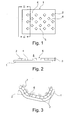
- the laminating film 1 in FIG. 1 consists of a substantially two-dimensional plastic film, which is intended to disguise an interior trim part for a motor vehicle to the user side and to a support member with the in FIG. 1 visible B-side to be laminated.
- a hotmelt is applied to the laminating film 1, in a plurality of diamonds 2 (numbered as an example).
- Each rhombus 2 has a height 3, with which it rises above a surface 4 of the B side 5 of the laminating film 1.
- the laminating film 1 is now laminated in a tool onto a carrier part 7 (cf. FIG. 3 ), the height 3 of the diamonds 2 from the hotmelt maintains the open connected property of the channel system 6. In the tool, the air can be removed laterally. It flows through the free cross sections of the channel system 6. In this case, the laminating film 1 moves step by step ever closer to the support part 7, until finally a direct fit occurs when the air is sucked out of the duct system 6.
- An embodiment of the invention already described provides for depressions to be introduced into the laminating film, for adhesive to be introduced into the depressions, and for the depressions of the laminating film to be flattened in a further step so that the adhesive passes to the surface of the laminating film.
- Such an example can be found in FIG. 4 shown:
- a laminating film 9 tapering in the machine direction 8 has embossed macroscopic depressions 10 (identified by way of example) which are filled with an adhesive 11 (numbered as an example).
- Each trough 10 receives a drop of adhesive 11.
- the laminating film 9 is guided through a station with two radiation heaters 14 (numbered as an example), which leads to heating of the laminating film 9.
- a memory effect in the plastic of the laminating film 9 causes the depressions 10 to recede in the area of the radiation heaters 14 and to become again flat with the surface 12 of the laminating film 9.
- the plastic of the laminating film 9 which resets in the memory effect, lifts the adhesive 11 out of the depressions 10, so that the adhesive ultimately protrudes from the film surface in droplets 15 and forms an open, interconnected channel system 16 (exemplarily numbered) between the droplets 15. forms.
- the film is heated prior to thermoforming.
- the embossed and filled with adhesive troughs back.
- the film becomes smooth again.
- the glue that was in the troughs becomes the excessive adhesive structure on the foil.
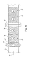
- the embossing roller 17 in the FIGS. 5 and 6 consists essentially of a conventional guide roller, wherein on a lateral surface 18 a plurality of macroscopically structured elevations 19 (numbered example) is arranged. Each individual elevation 19 can, for example, form a part-spherical body.
- a laminating film 20 runs through the plant in a machine direction 21, it is guided around the embossing roll 17 and assumes a multiplicity of hollows 22 (numbered as an example) (cf. FIGS. 7 and 8 ).
- the laminating film 20 provided with depressions 22 is guided along a slot die 23 at a minimum distance. From the slot die 23 occurs during the process of hot melt. Characterized in that the surface of the laminating film 20 between the wells 22 passes directly along the opening of the slot die 23, wherein in the ideal case no contact takes place, adhesive 24 exits only or at least predominantly in the wells 22.
- FIG. 9 A possible roller conveyor 25 for a system for laminating carrier parts with laminating films is shown in FIG. 9
- a laminating film 27 first enters a film store 28 with dancer rollers. After the film storage 28, the laminating film 27 continues to run and around a tempered embossing roll 29 by about 180 ° C.
- the embossing roller 29 transfers the laminating film 27 in the direction of travel directly to a pressure roller 30, which has on the film circulation side a slot die 31 for applying adhesive (not shown).
- a B-side 32 can therefore be fitted with troughs and adhesive, whereas an A-side 33 can remain untouched.
- the embodiment of the engraved roller 34 in the FIGS. 10a, 10b and 11 carries on its coat 35 a predominant area with a scar structure 36, which is preferably modeled on a natural leather.
- a scoring roller 34 can therefore produce individual scores 38, 39 (exemplified), each having a large grained area 40, but also a non-grained area 41 further in a machine direction 42, then the laminating film 43 passes through a station with a slot die 44, in which an adhesive application is made. This leads, with a suitable setting, to a larger, first area 45 on each individual end 38, 39 with adhesive applied, but also to a non-grained area 41 not provided with adhesive.
- Adhesive areas can be left out with this special design of the roller. Areas of application can be found for example in the adhesive savings in, for example, waste areas. In some door side panels, film sections are punched out after lamination. If there is no glue under these areas, then the punched blank can be more easily removed.
- the embossing roller may, for example, comprise a channel pattern.
- the photo 1 shows the remaining after heating and cooling drop structure of the adhesive application.
- the photo 2 shows an example of the adhesive structure after the release of the film from the component.
- the illustration 1 shows the remaining after heating and cooling drop structure of the adhesive application between the film and the component.
- the adhesive is a reactive or non-reactive thermoplastic hot melt adhesive, more preferably a hot melt adhesive based on ethylene vinyl acetates, polyacrylates, copolyamides, copolyesters, copolyethers, polyolefins, polyurethanes and corresponding co- and / or terpolymers.
- the components are interior components of vehicles.
- Such components consist in particular of materials based on natural fiber-reinforced polymer materials, for example a natural fiber, for example a flax polypropylene material, natural fiber, for example a (flax) PU or a natural fiber, for example (flax) epoxy resin material, and also a carrier produced by injection molding of polypropylene (PP), styrene-isoprene-styrene copolymer (ABS), polycarbonate-ABS (PCABS), polycarbonate (PC), thermoplastic polyurethane (TPU), thermoplastic polyolefin (TPO) or Polyamide comprises.
- PP polypropylene
- ABS styrene-isoprene-styrene copolymer
- PCABS polycarbonate-ABS
- PC polycarbonate
- TPU thermoplastic polyurethane
- TPO thermoplastic polyolefin
- Polyamide Polyamide
- the Figure 2 shows an example of an adhesive structure after the release of the film from the component.
- the bright shining channels which have allowed a uniform removal of the air between the component and the film have been completely preserved.
- Components with selected geometry and hole positioning have been shown to provide sufficient air transport within the adhesive grid over distances greater than 10 cm from the nearest hole, as well as over critical areas such as edges and radii.
- a plate-like component (240 mm diameter, 50 mm depth) made of polyoxymethylene (POM) without graining, with vacuum holes at a distance of about 2 cm in the outer edge region was laminated with the coated film to a single-station vacuum laminating the company KIEFEL (Germany), the bottom of the film being at 180 ° C, the top was heated to 140 ° C and the film was stretched in the longitudinal and transverse directions by 5%. Subsequently, the laminated component was inspected for imperfections due to air inclusions as well as the size of the laminated surface (for estimating the range of the air transport through the channels of the engraving).
- POM polyoxymethylene
Landscapes
- Engineering & Computer Science (AREA)
- Quality & Reliability (AREA)
- Manufacturing & Machinery (AREA)
- Chemical & Material Sciences (AREA)
- Organic Chemistry (AREA)
- Lining Or Joining Of Plastics Or The Like (AREA)
- Laminated Bodies (AREA)
- Physics & Mathematics (AREA)
- Fluid Mechanics (AREA)
Applications Claiming Priority (1)
| Application Number | Priority Date | Filing Date | Title |
|---|---|---|---|
| DE102014002568 | 2014-02-26 |
Publications (2)
| Publication Number | Publication Date |
|---|---|
| EP2913184A2 true EP2913184A2 (fr) | 2015-09-02 |
| EP2913184A3 EP2913184A3 (fr) | 2015-10-21 |
Family
ID=52573580
Family Applications (1)
| Application Number | Title | Priority Date | Filing Date |
|---|---|---|---|
| EP15000483.6A Withdrawn EP2913184A3 (fr) | 2014-02-26 | 2015-02-19 | Procédé d'application d'un adhésif sur une feuille de placage, procédé de placage d'un élément de support et installation de placage |
Country Status (6)
| Country | Link |
|---|---|
| US (1) | US10183474B2 (fr) |
| EP (1) | EP2913184A3 (fr) |
| CN (1) | CN104861883B (fr) |
| CA (1) | CA2882969A1 (fr) |
| DE (1) | DE102015001965A1 (fr) |
| MX (1) | MX2015002456A (fr) |
Cited By (2)
| Publication number | Priority date | Publication date | Assignee | Title |
|---|---|---|---|---|
| EP3124242B1 (fr) | 2015-07-28 | 2018-09-19 | SML Maschinengesellschaft m.b.H. | Procede et dispositif de fabrication d'une bande permeable a la vapeur d'eau |
| US10093084B2 (en) | 2014-02-26 | 2018-10-09 | Jowat Se | Laminating process employing grid-like adhesive application |
Families Citing this family (17)
| Publication number | Priority date | Publication date | Assignee | Title |
|---|---|---|---|---|
| EP2933089A1 (fr) * | 2014-04-14 | 2015-10-21 | Jowat SE | Procédé de lamination avec application d'adhésif en forme de grille |
| ES3060189T3 (en) * | 2016-03-31 | 2026-03-25 | Toray Industries | Reinforced fiber laminate sheet, fiber-reinforced resin molded body, and method for manufacturing reinforced fiber laminate sheet |
| DE102017005923A1 (de) | 2017-03-22 | 2018-09-27 | Kiefel Gmbh | Vorrichtung und verfahren zum auftragen von klebstoff, vorrichtung und verfahren zum aufkaschieren eines kaschierfolienelements auf ein bauteil, anlage zum kaschieren sowie verwendung eines ablageteils zum bereitstellen eines kaschierfolienelements |
| US11421381B2 (en) * | 2017-09-14 | 2022-08-23 | Lg Hausys, Ltd. | Artificial leather and method of manufacturing the same |
| CN107571524B (zh) * | 2017-09-26 | 2023-03-10 | 广东美的制冷设备有限公司 | 包装结构及其制造方法及空调器组件 |
| CN108838023A (zh) * | 2018-09-18 | 2018-11-20 | 苏州市贝地龙新型材料有限公司 | 一种底板生产表面滚涂装置及其滚涂工艺 |
| JP7360019B2 (ja) * | 2019-08-07 | 2023-10-12 | 横浜ゴム株式会社 | 接合体、及び基材の接合方法 |
| JP6870124B1 (ja) * | 2020-01-07 | 2021-05-12 | 豊田鉄工株式会社 | 表層付き部品の製造装置、及びその製造方法 |
| CN111204057B (zh) * | 2020-03-05 | 2024-06-18 | 安徽富印新材料股份有限公司 | 涂胶覆膜一体机 |
| CN111994367B (zh) * | 2020-08-11 | 2021-11-26 | 新乡市尊之尼科技有限公司 | 一种消毒湿巾生产设备及其生产工艺 |
| DE102021123195A1 (de) | 2021-09-08 | 2023-03-09 | Bayerische Motoren Werke Aktiengesellschaft | Verfahren zur Applikation eines wässrigen Klebstoffs auf eine Haptikschicht für ein Fahrzeugteil sowie Fahrzeugteil |
| CN114654820B (zh) * | 2022-03-21 | 2023-11-14 | 南通康净环保科技有限公司 | 一种抗病毒杀菌的空气净化设备用新型材料及其制备工艺 |
| CN114997018A (zh) * | 2022-06-16 | 2022-09-02 | 西安理工大学 | 一种计及夹带气体的导向辊处的牵引力计算方法 |
| CN115254528B (zh) * | 2022-06-27 | 2023-09-15 | 江苏奥力新材料股份有限公司 | 一种pp纸背胶涂抹工艺及其涂抹装置 |
| CN115246213B (zh) * | 2022-07-25 | 2025-04-15 | 西安工业大学 | 一种线路涂覆机器人封口加压装置 |
| CN115692607B (zh) * | 2022-12-04 | 2025-10-31 | 重庆石墨烯研究院有限公司 | 锂电池电极片及其制备方法 |
| CN116604810B (zh) * | 2023-05-25 | 2024-01-16 | 惠州市顺美医疗科技有限公司 | 一种导管鞘表面成型设备及其成型工艺 |
Citations (2)
| Publication number | Priority date | Publication date | Assignee | Title |
|---|---|---|---|---|
| DE10323617A1 (de) | 2003-05-26 | 2004-12-23 | Clariant Gmbh | Schmelzklebemassen |
| EP1508579A1 (fr) | 2003-08-21 | 2005-02-23 | Clariant GmbH | Cires de polyoléfine modifiées |
Family Cites Families (14)
| Publication number | Priority date | Publication date | Assignee | Title |
|---|---|---|---|---|
| US4822663A (en) * | 1988-01-26 | 1989-04-18 | Collins & Aikman Corporation | Crease resistant laminate |
| ES2141261T3 (es) * | 1993-10-29 | 2000-03-16 | Minnesota Mining & Mfg | Adhesivos piezosensibles con superficies microestructuradas. |
| GB2288162B (en) * | 1994-03-30 | 1997-11-26 | Harrison & Sons Ltd | Self-adhesive stamps |
| US6197397B1 (en) * | 1996-12-31 | 2001-03-06 | 3M Innovative Properties Company | Adhesives having a microreplicated topography and methods of making and using same |
| US6524675B1 (en) * | 1999-05-13 | 2003-02-25 | 3M Innovative Properties Company | Adhesive-back articles |
| US6495229B1 (en) * | 1999-09-17 | 2002-12-17 | Avery Dennison Corporation | Pattern coated adhesive article |
| JP4398629B2 (ja) * | 2002-05-24 | 2010-01-13 | リンテック株式会社 | 粘着シート |
| US6872268B2 (en) * | 2002-06-11 | 2005-03-29 | 3M Innovative Properties Company | Method of conforming an adherent film to a substrate by application of vacuum |
| DE102004035697A1 (de) * | 2004-02-06 | 2005-09-01 | Peter Ludwig | Trennschichtträger |
| FR2873382B1 (fr) * | 2004-07-22 | 2008-06-06 | Laudan | Procede d'enduction de films adhesifs |
| JP2007046003A (ja) * | 2005-08-12 | 2007-02-22 | Three M Innovative Properties Co | 被着体の貼付方法 |
| DE102005061766A1 (de) * | 2005-12-23 | 2007-06-28 | Lohmann Gmbh & Co Kg | Abdeckung mit feinen Oberflächenstrukturen zur Verminderung der Luftblasenbildung bei der Applikation klebender Erzeugnisse |
| DE102005061768B4 (de) * | 2005-12-23 | 2017-06-22 | Lohmann Gmbh & Co. Kg | Abdeckung für Klebschichten von klebenden Erzeugnissen sowie Verfahren zur Herstellung und Verwendung derselben |
| JP5112780B2 (ja) * | 2007-08-03 | 2013-01-09 | リンテック株式会社 | 易貼付性粘着シート及びその製造方法 |
-
2015
- 2015-02-19 EP EP15000483.6A patent/EP2913184A3/fr not_active Withdrawn
- 2015-02-19 DE DE102015001965.1A patent/DE102015001965A1/de not_active Withdrawn
- 2015-02-25 US US14/631,225 patent/US10183474B2/en active Active
- 2015-02-25 CA CA2882969A patent/CA2882969A1/fr not_active Abandoned
- 2015-02-25 MX MX2015002456A patent/MX2015002456A/es unknown
- 2015-02-26 CN CN201510088707.7A patent/CN104861883B/zh active Active
Patent Citations (2)
| Publication number | Priority date | Publication date | Assignee | Title |
|---|---|---|---|---|
| DE10323617A1 (de) | 2003-05-26 | 2004-12-23 | Clariant Gmbh | Schmelzklebemassen |
| EP1508579A1 (fr) | 2003-08-21 | 2005-02-23 | Clariant GmbH | Cires de polyoléfine modifiées |
Cited By (3)
| Publication number | Priority date | Publication date | Assignee | Title |
|---|---|---|---|---|
| US10093084B2 (en) | 2014-02-26 | 2018-10-09 | Jowat Se | Laminating process employing grid-like adhesive application |
| EP3124242B1 (fr) | 2015-07-28 | 2018-09-19 | SML Maschinengesellschaft m.b.H. | Procede et dispositif de fabrication d'une bande permeable a la vapeur d'eau |
| US10384430B2 (en) | 2015-07-28 | 2019-08-20 | Sml Maschinengesellschaft M. B. H. | Method and device for the production of a water vapor permeable laminar sheet |
Also Published As
| Publication number | Publication date |
|---|---|
| US10183474B2 (en) | 2019-01-22 |
| US20150239224A1 (en) | 2015-08-27 |
| CA2882969A1 (fr) | 2015-08-26 |
| EP2913184A3 (fr) | 2015-10-21 |
| CN104861883A (zh) | 2015-08-26 |
| DE102015001965A1 (de) | 2015-08-27 |
| CN104861883B (zh) | 2020-05-08 |
| MX2015002456A (es) | 2015-10-14 |
Similar Documents
| Publication | Publication Date | Title |
|---|---|---|
| EP2913184A2 (fr) | Procédé d'application d'un adhésif sur une feuille de placage, procédé de placage d'un élément de support et installation de placage | |
| EP2933090B1 (fr) | Procédé de laminage avec application d'adhésif en forme de grille | |
| EP3024669B1 (fr) | Procédé de fabrication d'un panneau mural et de sol décoré | |
| EP1820641B1 (fr) | Procédé destiné au cachetage de feuilles de plastique sur des substrats de matières premières en bois, en particulier pour la production de surfaces hautement brillantes | |
| DE102010021892B4 (de) | Verfahren und Vorrichtung zur Kaschierung eines 3D-Trägerteils mit einem Schichtstoff | |
| WO2017174176A1 (fr) | Procédé et outil de formage pour former à chaud un matériau stratifié thermoplastique plan | |
| DE19818881A1 (de) | Vorrichtung und Verfahren zum Formen von Innenverkleidungen für Kraftfahrzeuge | |
| DE102007008889A1 (de) | Verfahren zur Erzeugung von nano- und/oder mikrostrukturierten Oberflächen in einer klebenden, insbesondere selbstklebenden Schicht | |
| DE10114952A1 (de) | Zusammengesetzter Formartikel, Verfahren zu seiner Herstellung, sowie Innenformwerkzeug und Metallformwerkzeug, die für die Herstellung eines Schaumstoffformartikels, der ein Formmuster aufweist, mit einer Oberflächenhaut verwendet werden | |
| EP2315668A1 (fr) | Procédé de laminage de surfaces à haut brillant | |
| EP1955840B1 (fr) | Procédé de fabrication d'un corps moulé | |
| EP2133273B1 (fr) | Procédé d'encadrement d'un objet à l'aide d'un film de protection | |
| US10093084B2 (en) | Laminating process employing grid-like adhesive application | |
| DE102012012470A1 (de) | Verfahren und Vorrichtung zur Herstellung eines Innenverkleidungsteils | |
| EP3882040A1 (fr) | Procédé d'application d'une feuille à un support au moyen d'une charge électrostatique | |
| EP3285986A1 (fr) | Procédé de fabrication d'un corps profilé décoratif, notamment d'une baguette de lisière | |
| DE102008062200A1 (de) | Trägerfreies Dekor | |
| EP0035251A1 (fr) | Pièces formées en matière synthétique; leur procédé de fabrication et leurs applications | |
| DE102009022980A1 (de) | Schutzfolie für Oberflächen | |
| EP4261046B1 (fr) | Procédé de fabrication d'un panneau décoratif à synchronisation améliorée du décor et de la structure | |
| EP3084099A1 (fr) | Élément de sol stratifié | |
| DE19916565A1 (de) | Verfahren und Vorrichtung zum dreidimensionalen Kaschieren von plattenförmigen Werkstücken | |
| DE102012020484B4 (de) | Verfahren zur Herstellung eines wenigstens zwei Schichten aufweisenden Bauteils und Bauteil | |
| EP2052585A1 (fr) | Composant tridimensionnel luminescent et procédé de fabrication dudit composant | |
| DE7907294U1 (de) | Verbundkoerper |
Legal Events
| Date | Code | Title | Description |
|---|---|---|---|
| PUAI | Public reference made under article 153(3) epc to a published international application that has entered the european phase |
Free format text: ORIGINAL CODE: 0009012 |
|
| AK | Designated contracting states |
Kind code of ref document: A2 Designated state(s): AL AT BE BG CH CY CZ DE DK EE ES FI FR GB GR HR HU IE IS IT LI LT LU LV MC MK MT NL NO PL PT RO RS SE SI SK SM TR |
|
| AX | Request for extension of the european patent |
Extension state: BA ME |
|
| PUAL | Search report despatched |
Free format text: ORIGINAL CODE: 0009013 |
|
| AK | Designated contracting states |
Kind code of ref document: A3 Designated state(s): AL AT BE BG CH CY CZ DE DK EE ES FI FR GB GR HR HU IE IS IT LI LT LU LV MC MK MT NL NO PL PT RO RS SE SI SK SM TR |
|
| AX | Request for extension of the european patent |
Extension state: BA ME |
|
| RIC1 | Information provided on ipc code assigned before grant |
Ipc: B29C 63/00 20060101ALI20150911BHEP Ipc: C09J 7/02 20060101ALI20150911BHEP Ipc: B32B 37/12 20060101ALI20150911BHEP Ipc: B32B 37/00 20060101AFI20150911BHEP |
|
| 17P | Request for examination filed |
Effective date: 20160309 |
|
| RBV | Designated contracting states (corrected) |
Designated state(s): AL AT BE BG CH CY CZ DE DK EE ES FI FR GB GR HR HU IE IS IT LI LT LU LV MC MK MT NL NO PL PT RO RS SE SI SK SM TR |
|
| STAA | Information on the status of an ep patent application or granted ep patent |
Free format text: STATUS: EXAMINATION IS IN PROGRESS |
|
| 17Q | First examination report despatched |
Effective date: 20191105 |
|
| RAP1 | Party data changed (applicant data changed or rights of an application transferred) |
Owner name: PERSICO S.P.A. |
|
| REG | Reference to a national code |
Ref country code: DE Ref legal event code: R079 Free format text: PREVIOUS MAIN CLASS: B32B0037000000 Ipc: C09J0007200000 |
|
| GRAP | Despatch of communication of intention to grant a patent |
Free format text: ORIGINAL CODE: EPIDOSNIGR1 |
|
| STAA | Information on the status of an ep patent application or granted ep patent |
Free format text: STATUS: GRANT OF PATENT IS INTENDED |
|
| RIC1 | Information provided on ipc code assigned before grant |
Ipc: B32B 38/06 20060101ALI20230201BHEP Ipc: B32B 37/10 20060101ALI20230201BHEP Ipc: B29C 63/00 20060101ALI20230201BHEP Ipc: B32B 37/12 20060101ALI20230201BHEP Ipc: B32B 37/00 20060101ALI20230201BHEP Ipc: C09J 7/20 20180101AFI20230201BHEP |
|
| INTG | Intention to grant announced |
Effective date: 20230224 |
|
| STAA | Information on the status of an ep patent application or granted ep patent |
Free format text: STATUS: THE APPLICATION IS DEEMED TO BE WITHDRAWN |
|
| 18D | Application deemed to be withdrawn |
Effective date: 20230707 |