EP2913307A1 - Aufbereitungssystem für schiffsballastwasser - Google Patents
Aufbereitungssystem für schiffsballastwasser Download PDFInfo
- Publication number
- EP2913307A1 EP2913307A1 EP12886910.4A EP12886910A EP2913307A1 EP 2913307 A1 EP2913307 A1 EP 2913307A1 EP 12886910 A EP12886910 A EP 12886910A EP 2913307 A1 EP2913307 A1 EP 2913307A1
- Authority
- EP
- European Patent Office
- Prior art keywords
- ozone
- ballast water
- conduit
- seawater
- treatment system
- Prior art date
- Legal status (The legal status is an assumption and is not a legal conclusion. Google has not performed a legal analysis and makes no representation as to the accuracy of the status listed.)
- Withdrawn
Links
Images


Classifications
-
- C—CHEMISTRY; METALLURGY
- C02—TREATMENT OF WATER, WASTE WATER, SEWAGE, OR SLUDGE
- C02F—TREATMENT OF WATER, WASTE WATER, SEWAGE, OR SLUDGE
- C02F1/00—Treatment of water, waste water, or sewage
- C02F1/72—Treatment of water, waste water, or sewage by oxidation
- C02F1/78—Treatment of water, waste water, or sewage by oxidation with ozone
-
- B—PERFORMING OPERATIONS; TRANSPORTING
- B01—PHYSICAL OR CHEMICAL PROCESSES OR APPARATUS IN GENERAL
- B01F—MIXING, e.g. DISSOLVING, EMULSIFYING OR DISPERSING
- B01F23/00—Mixing according to the phases to be mixed, e.g. dispersing or emulsifying
- B01F23/20—Mixing gases with liquids
-
- B—PERFORMING OPERATIONS; TRANSPORTING
- B01—PHYSICAL OR CHEMICAL PROCESSES OR APPARATUS IN GENERAL
- B01F—MIXING, e.g. DISSOLVING, EMULSIFYING OR DISPERSING
- B01F23/00—Mixing according to the phases to be mixed, e.g. dispersing or emulsifying
- B01F23/20—Mixing gases with liquids
- B01F23/23—Mixing gases with liquids by introducing gases into liquid media, e.g. for producing aerated liquids
- B01F23/232—Mixing gases with liquids by introducing gases into liquid media, e.g. for producing aerated liquids using flow-mixing means for introducing the gases, e.g. baffles
- B01F23/2323—Mixing gases with liquids by introducing gases into liquid media, e.g. for producing aerated liquids using flow-mixing means for introducing the gases, e.g. baffles by circulating the flow in guiding constructions or conduits
-
- B—PERFORMING OPERATIONS; TRANSPORTING
- B01—PHYSICAL OR CHEMICAL PROCESSES OR APPARATUS IN GENERAL
- B01F—MIXING, e.g. DISSOLVING, EMULSIFYING OR DISPERSING
- B01F23/00—Mixing according to the phases to be mixed, e.g. dispersing or emulsifying
- B01F23/20—Mixing gases with liquids
- B01F23/23—Mixing gases with liquids by introducing gases into liquid media, e.g. for producing aerated liquids
- B01F23/237—Mixing gases with liquids by introducing gases into liquid media, e.g. for producing aerated liquids characterised by the physical or chemical properties of gases or vapours introduced in the liquid media
- B01F23/2376—Mixing gases with liquids by introducing gases into liquid media, e.g. for producing aerated liquids characterised by the physical or chemical properties of gases or vapours introduced in the liquid media characterised by the gas being introduced
- B01F23/23761—Aerating, i.e. introducing oxygen containing gas in liquids
- B01F23/237613—Ozone
-
- B—PERFORMING OPERATIONS; TRANSPORTING
- B01—PHYSICAL OR CHEMICAL PROCESSES OR APPARATUS IN GENERAL
- B01F—MIXING, e.g. DISSOLVING, EMULSIFYING OR DISPERSING
- B01F25/00—Flow mixers; Mixers for falling materials, e.g. solid particles
- B01F25/30—Injector mixers
- B01F25/31—Injector mixers in conduits or tubes through which the main component flows
- B01F25/313—Injector mixers in conduits or tubes through which the main component flows wherein additional components are introduced in the centre of the conduit
-
- B—PERFORMING OPERATIONS; TRANSPORTING
- B63—SHIPS OR OTHER WATERBORNE VESSELS; RELATED EQUIPMENT
- B63J—AUXILIARIES ON VESSELS
- B63J4/00—Arrangements of installations for treating ballast water, waste water, sewage, sludge, or refuse, or for preventing environmental pollution not otherwise provided for
- B63J4/002—Arrangements of installations for treating ballast water, waste water, sewage, sludge, or refuse, or for preventing environmental pollution not otherwise provided for for treating ballast water
-
- B—PERFORMING OPERATIONS; TRANSPORTING
- B01—PHYSICAL OR CHEMICAL PROCESSES OR APPARATUS IN GENERAL
- B01F—MIXING, e.g. DISSOLVING, EMULSIFYING OR DISPERSING
- B01F23/00—Mixing according to the phases to be mixed, e.g. dispersing or emulsifying
- B01F23/20—Mixing gases with liquids
- B01F23/23—Mixing gases with liquids by introducing gases into liquid media, e.g. for producing aerated liquids
- B01F23/237—Mixing gases with liquids by introducing gases into liquid media, e.g. for producing aerated liquids characterised by the physical or chemical properties of gases or vapours introduced in the liquid media
- B01F23/2373—Mixing gases with liquids by introducing gases into liquid media, e.g. for producing aerated liquids characterised by the physical or chemical properties of gases or vapours introduced in the liquid media for obtaining fine bubbles, i.e. bubbles with a size below 100 µm
-
- B—PERFORMING OPERATIONS; TRANSPORTING
- B63—SHIPS OR OTHER WATERBORNE VESSELS; RELATED EQUIPMENT
- B63B—SHIPS OR OTHER WATERBORNE VESSELS; EQUIPMENT FOR SHIPPING
- B63B13/00—Conduits for emptying or ballasting; Self-bailing equipment; Scuppers
-
- C—CHEMISTRY; METALLURGY
- C02—TREATMENT OF WATER, WASTE WATER, SEWAGE, OR SLUDGE
- C02F—TREATMENT OF WATER, WASTE WATER, SEWAGE, OR SLUDGE
- C02F2103/00—Nature of the water, waste water, sewage or sludge to be treated
- C02F2103/008—Originating from marine vessels, ships and boats, e.g. bilge water or ballast water
-
- C—CHEMISTRY; METALLURGY
- C02—TREATMENT OF WATER, WASTE WATER, SEWAGE, OR SLUDGE
- C02F—TREATMENT OF WATER, WASTE WATER, SEWAGE, OR SLUDGE
- C02F2303/00—Specific treatment goals
- C02F2303/04—Disinfection
-
- C—CHEMISTRY; METALLURGY
- C02—TREATMENT OF WATER, WASTE WATER, SEWAGE, OR SLUDGE
- C02F—TREATMENT OF WATER, WASTE WATER, SEWAGE, OR SLUDGE
- C02F2305/00—Use of specific compounds during water treatment
- C02F2305/02—Specific form of oxidant
Definitions
- the present invention relates to a ship ballast water treatment system, and more particularly, to a ship ballast water treatment system, which can sterilize ballast water stored in a plurality of ballast tanks disposed in a ship and receiving seawater to improve stability of the ship.
- ships such as LNG carriers, LPG carriers, container ships, bulk carriers, and tankers are designed to transport cargo in navigation.
- the center of gravity of the ship can be shifted upwards, causing instability of the ship.
- the ship can be exposed to impact of waves striking the bottom of the ship, that is, a slamming phenomenon, and also suffers from a propeller racing phenomenon in which the propeller is not fully submerged in water and emerges from a water surface, causing decrease in propulsion performance or increase in load fluctuation on the propeller and main engines, and a problem of deterioration in maneuverability due to insufficient submersion of a rudder in the water.
- ballast water the water stored in the ballast tank.
- Ballast water serves to provide stable adjustment of draft and trim (defined as a longitudinal inclination of a ship) depending upon the amount of cargo loaded on the ship. As described above, if ballast water is not supplied into the ship after cargo is completely unloaded from the ship, it is difficult for the ship to maintain a sufficient draft only with an inherent weight thereof.
- the bow of the ship can severely emerge from the water surface, or the propeller of the ship can be insufficiently submerged in the seawater, thereby causing bow slamming, deterioration of propulsion performance, or deterioration in maneuverability. Therefore, it is necessary for ships to use the ballast water.
- ballast water provides a problem. That is, marine contamination can occur due to microorganisms or marine organisms in the course of supplying or discharging the ballast water into or from the ballast tanks.
- ballast water supplied into a ship in one nation is discharged therefrom in another nation having a completely different environment, various foreign substances, microorganisms, viruses, and other organic materials of the one nation can disturb the marine ecosystem of the other nation.
- ballast water and sediments In consideration of such danger, strengthened international regulations on ballast water and sediments, enforced starting in 2009, require that ballast water be discharged only after sterilization of 99% microorganisms in the ballast water in order to prevent propagation of toxic microorganisms included in the ballast water. As such, the strengthened international regulations on ballast water and sediments increase difficulty in treatment of ballast water and promote development of various techniques related to a ballast water treatment apparatus.
- ballast water treatment apparatus wherein sodium hypochlorite generated through electrolysis of seawater is added to ballast water for sterilization of the ballast water, only some microorganisms can be removed through an indirect method, thereby providing low sterilization efficiency and difficulty in control of a sterilization material.
- ballast water treatment apparatus separately employing a filtration device and an electrolysis device performs sterilization of ballast water through many processes, thereby requiring a very complicated operation mechanism and a large space.
- this apparatus can sterilize some microorganisms through an indirect method, thereby providing low sterilization efficiency and difficulty in control of a sterilization material.
- a ship ballast water treatment system includes: an ozone bubbling unit disposed inside a conduit through which ballast water flows and converting ozone supplied thereto into bubbles; a seawater supply channel provided as a separate line not diverging from the conduit and connected at one end thereof to the ozone bubbling unit, and supplying seawater to the ozone bubbling unit therethrough; and a seawater pumping unit provided to the seawater supply channel and pumping the seawater into the ozone bubbling unit.
- the ozone bubbling unit may include a bubble nozzle connected to the one end of the seawater supply channel and converting the supplied ozone into ozone microbubbles using the seawater; and a spreading unit provided to an outlet of the bubble nozzle and spreading the ozone microbubbles.
- the conduit may include a main conduit and a connecting conduit detachably connected between pieces of the main conduit, and the ozone bubbling unit may be disposed in the connecting conduit.
- Both ends of the connecting conduit may have the same diameter as that of the main conduit, and a central portion of the connecting conduit may have a larger diameter than that of both ends thereof to allow the ozone bubbles to be spread therethrough.
- the ozone bubbling unit may be placed at the central portion of the connecting conduit.
- the seawater pumping unit may include a pump disposed in the seawater supply channel; and a motor provided to the pump and operating the pump.
- the ozone may be supplied from an ozone generating unit disposed on a deck, and the ozone generating unit may include an oxygen generator disposed on the deck; an oxygen storage tank disposed on the deck and storing oxygen generated by the oxygen generator; and an ozone generator disposed on the deck and generating ozone using oxygen supplied from the oxygen storage tank.
- the oxygen generator, the oxygen storage tank and the ozone generator may be disposed inside a container placed on the deck.
- the ozone generated by the ozone generator may be supplied into the ozone bubbling unit through a double-pipe.
- a ship ballast water treatment system includes: an ozone bubbling unit to which part of a conduit through which ballast water flows is detachably coupled, and converting ozone supplied into the part of the conduit into microbubbles using seawater, wherein the seawater is supplied through a separate line not diverging from the conduit.
- Embodiments of the preset invention can achieve efficient sterilization of ballast water by directly supplying ozone bubbles into a conduit through which the ballast water flows, while producing the ozone bubbles by supplying seawater through a separate line instead of the conduit such that a constant amount of ozone can be produced at a constant rate.
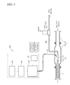
- Fig. 1 is a schematic diagram of a ship ballast water treatment system according to one embodiment of the present invention
- Fig. 2 is a plan view of the ship ballast water treatment system of Fig. 1 , in which an ozone generating unit is disposed on a deck
- Fig. 3 is a schematic diagram of main components of the ship ballast water treatment system of Fig. 1
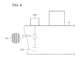
- Fig. 4 schematically shows an installation location of the ozone generating unit and a double-pipe in the ship ballast water treatment system of Fig. 1 .
- a ship ballast water treatment system 1 includes: an ozone bubbling unit 100 disposed inside a conduit L through which ballast water flows and converting ozone supplied thereto into bubbles; a seawater supply channel 200 provided as a separate line not diverging from the conduit L and connected at one end thereof to the ozone bubbling unit 100, and supplying seawater to the ozone bubbling unit 100 therethrough; a seawater pumping unit 300 provided to the seawater supply channel 200 and pumping the seawater into the ozone bubbling unit 100; and an ozone generating unit 400 disposed on a deck D of the ship.
- the ozone bubbling unit 100 is disposed inside the conduit L and converts ozone supplied thereto into ozone microbubbles using seawater while diffusively discharging the ozone microbubbles such that the ozone microbubbles can be dissolved in a wide surface area in the ballast water.
- the ozone bubbling unit 100 includes a bubble nozzle 110 connected to the one end of the seawater supply channel 200 and converting the supplied ozone into ozone microbubbles using seawater; and a spreading unit 120 provided to an outlet of the bubble nozzle 110 and spreading the ozone microbubbles.
- an ozone supply channel OL is detachably coupled to the bubble nozzle 110 of the ozone bubbling unit 100, and ozone generated from an ozone generating unit (see Fig. 2 ) flows into the bubble nozzle 110 through the ozone supply channel OL.
- the bubble nozzle 110 is provided therein with an ozone flow passage (not shown) communicating with the ozone supply channel OL, and a seawater flow passage (not shown) communicating with the seawater supply channel 200.
- a bottleneck portion having a narrower diameter than other portions of the seawater flow passage is formed in region of the seawater flow passage, at which the ozone flow passage meets the seawater flow passage.
- a negative pressure is generated and forces the supplied ozone to be suctioned from the ozone flow passage into the seawater flow passage such that the supplied ozone is converted into the ozone microbubbles and discharged together with the seawater through the outlet of the bubble nozzle.
- the outlet of the bubble nozzle 110 may be provided with a bubble layer (not shown) having a plurality of fine holes, whereby generation of the ozone microbubbles can be promoted while the supplied ozone passes through the bubble layer.
- the spreading unit 120 of the ozone bubbling unit 100 is provided to the outlet of the bubble nozzle 110, and an internal flow passage of a portion of the spreading unit connected to the seawater flow passage has the same diameter as that of the seawater flow passage and an internal flow passage in other regions of the spreading unit distant from the outlet of the bubble nozzle 110 has a larger diameter than the seawater flow passage, whereby the ozone microbubbles can be spread therethrough.
- the ozone bubbling unit 100 is illustrated as one example and may be replaced by any bubble nozzle known in the art.
- the ozone bubbling unit 100 may be composed only of the bubble nozzle 110 without the spreading unit 120.
- the conduit L through which ballast water flows includes a main conduit L1 and a connecting conduit L2 detachably connected between pieces of the main conduit L1, and the ozone bubbling unit 100 may be disposed at a central portion of the connecting conduit L2.
- both ends of the connecting conduit L2 may have the same diameter as that of the main conduit L1, and the central portion of the connection conduit L2 may have a larger diameter D than the diameter d of both ends thereof.
- a flange may be disposed at an interface between the main conduit L1 and the connecting conduit L2 such that the main conduit L1 and the connecting conduit L2 can be coupled to each other by bolts and nuts through the flange.
- a portion of an upper side of the connecting conduit may be cut and detachably coupled thereto by bolts and nuts.
- the seawater supply channel 200 is connected at one end thereof to the bubble nozzle 110 to supply seawater to the bubble nozzle 110 and is provided as a separate line not diverging from the conduit L.
- a constant amount of seawater can be supplied at a constant rate into bubble nozzle 110 without being influenced by the amount or flow rate of the ballast water flowing in the conduit L, thereby guaranteeing generation of the ozone microbubbles at a constant rate.
- the generating amount or speed of the ozone microbubbles depends on the ballast water within the conduit L.
- seawater can be stably and accurately supplied through the seawater supply channel 200, which is a separate line independent of the conduit L, thereby allowing constant generation of the ozone microbubbles.
- seawater supply channel 200 is connected at the other side thereof to a sea chest (not shown) or a sea.
- the seawater pumping unit 300 serves to supply the seawater at a high rate to the bubble nozzle 110, and includes a pump 310 provided to the seawater supply channel 200 and a motor 320 disposed at an upper side of the pump 310 to operate the pump 310, as shown in Figs. 1 and 3 .
- the ozone generating unit 400 is disposed on the deck D and generates ozone to supply ozone bubbles.
- the structure in which the ozone generating unit 400 is disposed on the deck D can solve a problem of complicated operation caused by a narrow installation space in the case that such an ozone generating unit is disposed within a ship as in the related art, and allows toxic gas to be diluted in air on the deck D instead of the interior of the ship in case of emergency, thereby providing safety.
- the ozone generating unit 400 may be disposed inside a container C, as shown in Fig. 2 . This structure allows easy work and provides convenience in installation and movement of the ozone generating unit.
- the ozone generating unit 400 includes an oxygen generator 410 disposed on the deck D and generating oxygen using air supplied thereto, an oxygen storage tank 420 disposed on the deck D and storing oxygen generated by the oxygen generator 410, an ozone generator 430 disposed on the deck D and generating ozone using oxygen supplied from the oxygen storage tank 420, a water chiller 440 configured to remove heat generated in the course of generating ozone, and a control panel 450 that controls these components 410 ⁇ 440.
- the ozone generator 430 may generate ozone in a silent discharge manner wherein, with a dielectric material such as glass or a ceramic material interposed between electrodes, oxygen is supplied into a discharge space and a high voltage of 6 kV ⁇ 15 kV is applied to the electrodes to induce reaction for generating ozone in the discharge space.
- the ozone gas generated by the ozone generator 430 may be supplied at a flow rate of 1 L/min into the conduit L, through which ballast water flows, such that the conduit L has an ozone concentration of 170g/cm 3 and an ozone injection amount of 2 mg/L.
- the ozone generator 430 may cool the ozone generator 430 using the water chiller 440, as shown in Fig. 1 .
- the water chiller 440 may perform a cooling function using cold fresh water, and the fresh water having high temperature resulting from heat exchange may be cooled again through a cooler.
- ozone generated by the ozone generator 430 is supplied to the ozone bubbling unit 100 disposed at the bottom of the ship through the ozone supply channel OL, which passes through a closed space.
- An ozone transport pipe is likely to suffer from corrosion due to characteristics of ozone.
- the ozone supply channel OL, through which ozone is transported may be realized by a double-pipe, as shown in Fig. 4 .
- the ozone supply channel OL may be provided with at least one valve (not shown), which may be opened or closed by a controller (not shown).
- the conduit L may be provided therein with at least one bubble sensor (not shown) capable of measuring the amount of bubbles generated, and the controller may regulate the degree of opening of the at least one valve provided to the ozone supply channel OL and power of the pump 310 based on the amount of the generated bubbles measured by the bubble sensor.
- Fig. 5 schematically shows the ship ballast water treatment system according to the embodiment of the present invention in use. Next, operation of the ship ballast water treatment system according to this embodiment will be described with reference to Fig. 5 .
- Ozone generated in the ozone generating unit 400 is supplied to the ozone bubbling unit 100 through the ozone supply channel OL.
- the ozone bubbling unit 100 converts the supplied ozone into ozone microbubbles using seawater supplied through the seawater supply channel 200.
- the ozone bubbling unit 100 spreads the ozone microbubbles such that the ozone microbubbles can be dissolved in a wide surface area in ballast water. It can be seen that the ozone microbubbles can be more efficiently spread due to decrease in inflow rate of ballast water resulting from a larger diameter of the central portion of the connecting conduit L2 than that of the main conduit L1.
- generation of the ozone microbubbles in the ozone bubbling unit 100 is carried out using the seawater supplied through the seawater supply channel 200 instead of ballast water flowing through the conduit L, and is thus not affected by the amount or flow rate of the ballast water in the conduit L, thereby providing an advantage of generating a constant amount of the ozone microbubbles at a constant rate.
- ozone is converted into bubbles, which in turn are directly supplied into the conduit through which ballast water flows, thereby enabling efficient sterilization of the ballast water, and seawater is supplied to generate ozone bubbles through a separate line instead of the conduit, thereby providing an advantage of generating a constant amount of the ozone bubbles at a constant rate.
Landscapes
- Chemical & Material Sciences (AREA)
- Engineering & Computer Science (AREA)
- Chemical Kinetics & Catalysis (AREA)
- Environmental & Geological Engineering (AREA)
- Combustion & Propulsion (AREA)
- Hydrology & Water Resources (AREA)
- Water Supply & Treatment (AREA)
- Organic Chemistry (AREA)
- Life Sciences & Earth Sciences (AREA)
- Mechanical Engineering (AREA)
- Ocean & Marine Engineering (AREA)
- Health & Medical Sciences (AREA)
- General Health & Medical Sciences (AREA)
- Public Health (AREA)
- Toxicology (AREA)
- Treatment Of Water By Oxidation Or Reduction (AREA)
- Oxygen, Ozone, And Oxides In General (AREA)
Applications Claiming Priority (2)
| Application Number | Priority Date | Filing Date | Title |
|---|---|---|---|
| KR1020120117862A KR101351301B1 (ko) | 2012-10-23 | 2012-10-23 | 선박의 밸러스트수 처리시스템 |
| PCT/KR2012/009341 WO2014065458A1 (ko) | 2012-10-23 | 2012-11-07 | 선박의 밸러스트수 처리시스템 |
Publications (2)
| Publication Number | Publication Date |
|---|---|
| EP2913307A1 true EP2913307A1 (de) | 2015-09-02 |
| EP2913307A4 EP2913307A4 (de) | 2016-07-13 |
Family
ID=50145512
Family Applications (1)
| Application Number | Title | Priority Date | Filing Date |
|---|---|---|---|
| EP12886910.4A Withdrawn EP2913307A4 (de) | 2012-10-23 | 2012-11-07 | Aufbereitungssystem für schiffsballastwasser |
Country Status (6)
| Country | Link |
|---|---|
| US (1) | US20150274560A1 (de) |
| EP (1) | EP2913307A4 (de) |
| JP (1) | JP2016502476A (de) |
| KR (1) | KR101351301B1 (de) |
| CN (1) | CN104755434A (de) |
| WO (1) | WO2014065458A1 (de) |
Cited By (1)
| Publication number | Priority date | Publication date | Assignee | Title |
|---|---|---|---|---|
| EP3421418A1 (de) * | 2017-06-30 | 2019-01-02 | SUEZ Groupe | Ozonerzeugungsmaschine zur verwendung in einem schiff |
Families Citing this family (3)
| Publication number | Priority date | Publication date | Assignee | Title |
|---|---|---|---|---|
| EP3421419B1 (de) * | 2017-06-30 | 2020-02-12 | SUEZ Groupe | Ozonerzeugungsmaschine mit elektrischem, geschlossenem schrank, der von einem geschlossenen regelkreis gekühlt wird |
| CN108946915A (zh) * | 2018-08-10 | 2018-12-07 | 苏州拓拓家软件科技有限公司 | 船舶压载水处理系统 |
| KR102799348B1 (ko) * | 2023-01-30 | 2025-04-23 | 에스엔시스(주) | 버블 생성 장치 및 이를 이용한 선박 평형수 처리 시스템 |
Family Cites Families (27)
| Publication number | Priority date | Publication date | Assignee | Title |
|---|---|---|---|---|
| US4019983A (en) * | 1974-10-10 | 1977-04-26 | Houdaille Industries, Inc. | Disinfection system and method |
| EP0869841B1 (de) * | 1996-07-01 | 2003-06-04 | Heurtaux S.a.s. | Schaumstoffherstellungsvorrichtung |
| US20030015481A1 (en) * | 2001-06-28 | 2003-01-23 | Eidem Ola Magne | Method and apparatus for treating/disinfecting ballast water in ships |
| JP2003154380A (ja) * | 2001-11-21 | 2003-05-27 | Sasakura Engineering Co Ltd | 高濃度オゾンによる水処理方法及び水処理装置 |
| NO20034330D0 (no) * | 2003-09-26 | 2003-09-26 | Norsk Hydro As | Fremgangsmåte for blanding av to fluider og mikser for utövelse av slik fremgangsmåte |
| KR20050104001A (ko) * | 2004-04-27 | 2005-11-02 | 김수영 | 선박용 밸러스트 수 처리방법 및 장치 |
| CN2734317Y (zh) * | 2004-09-21 | 2005-10-19 | 科达生技股份有限公司 | 压力式气液混合器 |
| JP4964120B2 (ja) * | 2005-01-24 | 2012-06-27 | ニューテック オースリー インコーポレイテッド | オゾンを注入する方法およびシステム |
| JP2006263505A (ja) * | 2005-03-22 | 2006-10-05 | Global Trust:Kk | 水処理方法及び装置 |
| JP2006263563A (ja) * | 2005-03-23 | 2006-10-05 | Mitsui Eng & Shipbuild Co Ltd | バラスト水中の微生物等の殺減装置 |
| CN2796713Y (zh) * | 2005-04-29 | 2006-07-19 | 中国农业大学 | 臭氧-紫外线营养液消毒器 |
| CN2810731Y (zh) * | 2005-06-07 | 2006-08-30 | 吴镇霖 | 臭氧水机混合器 |
| JP4948962B2 (ja) * | 2006-10-16 | 2012-06-06 | 住友重機械工業株式会社 | 高濃度オゾン水製造装置及び高濃度オゾン水製造方法 |
| JP4384184B2 (ja) * | 2007-02-02 | 2009-12-16 | 三井造船株式会社 | バラスト処理水供給船 |
| KR100775238B1 (ko) * | 2007-02-22 | 2007-11-28 | 주식회사 엔케이 | 벤추리형혼합기와 오존공급장치를 갖는 밸러스트수 처리장치 |
| KR100802889B1 (ko) | 2007-02-27 | 2008-02-13 | 주식회사 엔케이 | 오존공급장치와 반응탱크를 갖는 밸러스트수 처리장치 |
| JP4885829B2 (ja) * | 2007-11-26 | 2012-02-29 | 三井造船株式会社 | オゾン混合器 |
| JP4688085B2 (ja) * | 2008-01-07 | 2011-05-25 | 三井造船株式会社 | バラスト水の処理装置 |
| JP2010075838A (ja) * | 2008-09-25 | 2010-04-08 | Itaken:Kk | 気泡発生ノズル |
| KR20100104973A (ko) * | 2009-03-20 | 2010-09-29 | 장계원 | 마이크로 버블용 노즐과 버블 발생 모듈 |
| JP5021700B2 (ja) * | 2009-07-31 | 2012-09-12 | 三井造船株式会社 | バラスト処理水供給船 |
| CN201517047U (zh) * | 2009-09-14 | 2010-06-30 | 江苏华阳重工科技股份有限公司 | 船舶压载水臭氧灭菌装置 |
| KR101191147B1 (ko) * | 2010-07-30 | 2012-10-15 | 한국기계연구원 | 마이크로 버블을 이용한 전기분해식 선박 평형수 살균 처리장치 |
| CN201857322U (zh) * | 2010-09-29 | 2011-06-08 | 南通海景船舶压载水处理系统股份有限公司 | 船舶压载水综合处理系统 |
| WO2012053224A1 (ja) * | 2010-10-22 | 2012-04-26 | パナソニック株式会社 | バラスト水処理システム及びバラスト水処理方法 |
| CN201949826U (zh) * | 2011-03-17 | 2011-08-31 | 中国水产科学研究院黑龙江水产研究所 | 微气泡气液混合装置 |
| JP3172935U (ja) * | 2011-10-28 | 2012-01-12 | 株式会社シーメイト | 船舶 |
-
2012
- 2012-10-23 KR KR1020120117862A patent/KR101351301B1/ko not_active Expired - Fee Related
- 2012-11-07 CN CN201280076622.1A patent/CN104755434A/zh active Pending
- 2012-11-07 US US14/437,847 patent/US20150274560A1/en not_active Abandoned
- 2012-11-07 WO PCT/KR2012/009341 patent/WO2014065458A1/ko not_active Ceased
- 2012-11-07 EP EP12886910.4A patent/EP2913307A4/de not_active Withdrawn
- 2012-11-07 JP JP2015539483A patent/JP2016502476A/ja active Pending
Cited By (5)
| Publication number | Priority date | Publication date | Assignee | Title |
|---|---|---|---|---|
| EP3421418A1 (de) * | 2017-06-30 | 2019-01-02 | SUEZ Groupe | Ozonerzeugungsmaschine zur verwendung in einem schiff |
| WO2019002530A1 (en) * | 2017-06-30 | 2019-01-03 | Suez Groupe | OZONE GENERATING MACHINE FOR USE IN A SHIP |
| CN110944939A (zh) * | 2017-06-30 | 2020-03-31 | 苏伊士集团 | 船舶用臭氧发生机器 |
| US11370661B2 (en) | 2017-06-30 | 2022-06-28 | E2Interactive, Inc. | Ozone generating machine for use in a ship |
| CN110944939B (zh) * | 2017-06-30 | 2023-02-17 | 苏伊士集团 | 船舶用臭氧发生机器 |
Also Published As
| Publication number | Publication date |
|---|---|
| EP2913307A4 (de) | 2016-07-13 |
| CN104755434A (zh) | 2015-07-01 |
| WO2014065458A1 (ko) | 2014-05-01 |
| KR101351301B1 (ko) | 2014-01-15 |
| US20150274560A1 (en) | 2015-10-01 |
| JP2016502476A (ja) | 2016-01-28 |
Similar Documents
| Publication | Publication Date | Title |
|---|---|---|
| EP2913308A1 (de) | Aufbereitungssystem für schiffsballastwasser | |
| EP2913307A1 (de) | Aufbereitungssystem für schiffsballastwasser | |
| US7921790B2 (en) | Ship buoyancy control system | |
| KR20110073868A (ko) | 흘수조절이 자유로운 유동 밸러스트구조를 구비한 공기쿠션선박 | |
| KR20190058117A (ko) | 선박의 발전 시스템 및 방법 | |
| JP3172935U (ja) | 船舶 | |
| KR20140046878A (ko) | 선박 | |
| KR20130108764A (ko) | 밸러스트수 처리장치가 필요없는 선박 | |
| JP2008195114A (ja) | 係船装置、船及びバラスト処理水供給船 | |
| JP2008188502A (ja) | 水処理装置及び水処理方法 | |
| KR101004916B1 (ko) | 부력 조절통을 갖는 선박 | |
| CN101600620A (zh) | 压载处理水供给船及压载处理水的供给方法 | |
| JP2006263563A (ja) | バラスト水中の微生物等の殺減装置 | |
| KR20150021983A (ko) | 논 밸러스트 선박 | |
| KR101252577B1 (ko) | 선박의 밸러스트수 처리시스템 | |
| JP2012245852A (ja) | 液化燃料輸送船及び船舶の改造方法、船舶並びに液化燃料輸送船 | |
| JPH11310188A (ja) | 船舶の摩擦抵抗低減装置 | |
| KR101323794B1 (ko) | 선박 | |
| JP4153758B2 (ja) | 移動式水質浄化装置 | |
| KR101536015B1 (ko) | 부력 조절 선박 | |
| CN109070973B (zh) | 大型排水型船体船 | |
| WO2019003380A1 (ja) | バラスト水処理装置 | |
| JP4365331B2 (ja) | 水中の残留オゾン除去方法及びバラスト水中の残留オゾン除去方法 | |
| KR20140090396A (ko) | 논 밸러스트 선박 | |
| EP4385954A1 (de) | Reinigung eines nautischen schiffs |
Legal Events
| Date | Code | Title | Description |
|---|---|---|---|
| PUAI | Public reference made under article 153(3) epc to a published international application that has entered the european phase |
Free format text: ORIGINAL CODE: 0009012 |
|
| 17P | Request for examination filed |
Effective date: 20150522 |
|
| AK | Designated contracting states |
Kind code of ref document: A1 Designated state(s): AL AT BE BG CH CY CZ DE DK EE ES FI FR GB GR HR HU IE IS IT LI LT LU LV MC MK MT NL NO PL PT RO RS SE SI SK SM TR |
|
| AX | Request for extension of the european patent |
Extension state: BA ME |
|
| RIN1 | Information on inventor provided before grant (corrected) |
Inventor name: LEE, YOUNG MAN Inventor name: CHOI, KUM SIK |
|
| DAX | Request for extension of the european patent (deleted) | ||
| RA4 | Supplementary search report drawn up and despatched (corrected) |
Effective date: 20160613 |
|
| RIC1 | Information provided on ipc code assigned before grant |
Ipc: C02F 7/00 20060101ALI20160607BHEP Ipc: C02F 103/00 20060101ALN20160607BHEP Ipc: B63B 13/00 20060101ALN20160607BHEP Ipc: B01F 3/04 20060101ALI20160607BHEP Ipc: B01F 5/04 20060101ALI20160607BHEP Ipc: C02F 1/78 20060101AFI20160607BHEP |
|
| STAA | Information on the status of an ep patent application or granted ep patent |
Free format text: STATUS: THE APPLICATION IS DEEMED TO BE WITHDRAWN |
|
| 18D | Application deemed to be withdrawn |
Effective date: 20170111 |