EP2913544A2 - Couronne d'orientation en Forme de palier lisse - Google Patents
Couronne d'orientation en Forme de palier lisse Download PDFInfo
- Publication number
- EP2913544A2 EP2913544A2 EP15405018.1A EP15405018A EP2913544A2 EP 2913544 A2 EP2913544 A2 EP 2913544A2 EP 15405018 A EP15405018 A EP 15405018A EP 2913544 A2 EP2913544 A2 EP 2913544A2
- Authority
- EP
- European Patent Office
- Prior art keywords
- elements
- sliding
- bearing according
- connection
- sub
- Prior art date
- Legal status (The legal status is an assumption and is not a legal conclusion. Google has not performed a legal analysis and makes no representation as to the accuracy of the status listed.)
- Granted
Links
- 230000036316 preload Effects 0.000 claims description 13
- 229920003023 plastic Polymers 0.000 claims description 7
- 239000004033 plastic Substances 0.000 claims description 7
- 230000013011 mating Effects 0.000 claims description 2
- 238000004519 manufacturing process Methods 0.000 abstract description 7
- 238000002347 injection Methods 0.000 abstract description 4
- 239000007924 injection Substances 0.000 abstract description 4
- 239000002184 metal Substances 0.000 description 7
- 238000000034 method Methods 0.000 description 4
- 238000005096 rolling process Methods 0.000 description 4
- 238000003860 storage Methods 0.000 description 3
- 210000000689 upper leg Anatomy 0.000 description 3
- 239000000853 adhesive Substances 0.000 description 2
- 230000001070 adhesive effect Effects 0.000 description 2
- 230000000295 complement effect Effects 0.000 description 2
- 238000010276 construction Methods 0.000 description 2
- 239000010408 film Substances 0.000 description 2
- 238000000465 moulding Methods 0.000 description 2
- 238000003825 pressing Methods 0.000 description 2
- 238000007789 sealing Methods 0.000 description 2
- 239000007787 solid Substances 0.000 description 2
- 239000002344 surface layer Substances 0.000 description 2
- 239000010409 thin film Substances 0.000 description 2
- 230000009471 action Effects 0.000 description 1
- 230000004913 activation Effects 0.000 description 1
- 238000004026 adhesive bonding Methods 0.000 description 1
- 230000000712 assembly Effects 0.000 description 1
- 238000000429 assembly Methods 0.000 description 1
- 239000002131 composite material Substances 0.000 description 1
- 230000001419 dependent effect Effects 0.000 description 1
- 238000006073 displacement reaction Methods 0.000 description 1
- 238000005516 engineering process Methods 0.000 description 1
- 230000002349 favourable effect Effects 0.000 description 1
- 239000011888 foil Substances 0.000 description 1
- 230000012447 hatching Effects 0.000 description 1
- 238000001746 injection moulding Methods 0.000 description 1
- 238000003780 insertion Methods 0.000 description 1
- 230000037431 insertion Effects 0.000 description 1
- 230000010354 integration Effects 0.000 description 1
- 239000010410 layer Substances 0.000 description 1
- 230000014759 maintenance of location Effects 0.000 description 1
- 239000000463 material Substances 0.000 description 1
- 238000007639 printing Methods 0.000 description 1
- 230000009467 reduction Effects 0.000 description 1
- 238000010079 rubber tapping Methods 0.000 description 1
- 239000011265 semifinished product Substances 0.000 description 1
- 239000012791 sliding layer Substances 0.000 description 1
- 238000005507 spraying Methods 0.000 description 1
- 230000008719 thickening Effects 0.000 description 1
Images



Classifications
-
- F—MECHANICAL ENGINEERING; LIGHTING; HEATING; WEAPONS; BLASTING
- F16—ENGINEERING ELEMENTS AND UNITS; GENERAL MEASURES FOR PRODUCING AND MAINTAINING EFFECTIVE FUNCTIONING OF MACHINES OR INSTALLATIONS; THERMAL INSULATION IN GENERAL
- F16C—SHAFTS; FLEXIBLE SHAFTS; ELEMENTS OR CRANKSHAFT MECHANISMS; ROTARY BODIES OTHER THAN GEARING ELEMENTS; BEARINGS
- F16C33/00—Parts of bearings; Special methods for making bearings or parts thereof
- F16C33/02—Parts of sliding-contact bearings
- F16C33/04—Brasses; Bushes; Linings
- F16C33/046—Brasses; Bushes; Linings divided or split, e.g. half-bearings or rolled sleeves
-
- F—MECHANICAL ENGINEERING; LIGHTING; HEATING; WEAPONS; BLASTING
- F16—ENGINEERING ELEMENTS AND UNITS; GENERAL MEASURES FOR PRODUCING AND MAINTAINING EFFECTIVE FUNCTIONING OF MACHINES OR INSTALLATIONS; THERMAL INSULATION IN GENERAL
- F16C—SHAFTS; FLEXIBLE SHAFTS; ELEMENTS OR CRANKSHAFT MECHANISMS; ROTARY BODIES OTHER THAN GEARING ELEMENTS; BEARINGS
- F16C17/00—Sliding-contact bearings for exclusively rotary movement
- F16C17/10—Sliding-contact bearings for exclusively rotary movement for both radial and axial load
- F16C17/102—Sliding-contact bearings for exclusively rotary movement for both radial and axial load with grooves in the bearing surface to generate hydrodynamic pressure
- F16C17/105—Sliding-contact bearings for exclusively rotary movement for both radial and axial load with grooves in the bearing surface to generate hydrodynamic pressure with at least one bearing surface providing angular contact, e.g. conical or spherical bearing surfaces
-
- F—MECHANICAL ENGINEERING; LIGHTING; HEATING; WEAPONS; BLASTING
- F16—ENGINEERING ELEMENTS AND UNITS; GENERAL MEASURES FOR PRODUCING AND MAINTAINING EFFECTIVE FUNCTIONING OF MACHINES OR INSTALLATIONS; THERMAL INSULATION IN GENERAL
- F16C—SHAFTS; FLEXIBLE SHAFTS; ELEMENTS OR CRANKSHAFT MECHANISMS; ROTARY BODIES OTHER THAN GEARING ELEMENTS; BEARINGS
- F16C25/00—Bearings for exclusively rotary movement adjustable for wear or play
- F16C25/02—Sliding-contact bearings
-
- F—MECHANICAL ENGINEERING; LIGHTING; HEATING; WEAPONS; BLASTING
- F16—ENGINEERING ELEMENTS AND UNITS; GENERAL MEASURES FOR PRODUCING AND MAINTAINING EFFECTIVE FUNCTIONING OF MACHINES OR INSTALLATIONS; THERMAL INSULATION IN GENERAL
- F16C—SHAFTS; FLEXIBLE SHAFTS; ELEMENTS OR CRANKSHAFT MECHANISMS; ROTARY BODIES OTHER THAN GEARING ELEMENTS; BEARINGS
- F16C43/00—Assembling bearings
- F16C43/02—Assembling sliding-contact bearings
-
- F—MECHANICAL ENGINEERING; LIGHTING; HEATING; WEAPONS; BLASTING
- F16—ENGINEERING ELEMENTS AND UNITS; GENERAL MEASURES FOR PRODUCING AND MAINTAINING EFFECTIVE FUNCTIONING OF MACHINES OR INSTALLATIONS; THERMAL INSULATION IN GENERAL
- F16C—SHAFTS; FLEXIBLE SHAFTS; ELEMENTS OR CRANKSHAFT MECHANISMS; ROTARY BODIES OTHER THAN GEARING ELEMENTS; BEARINGS
- F16C2226/00—Joining parts; Fastening; Assembling or mounting parts
- F16C2226/50—Positive connections
- F16C2226/60—Positive connections with threaded parts, e.g. bolt and nut connections
-
- F—MECHANICAL ENGINEERING; LIGHTING; HEATING; WEAPONS; BLASTING
- F16—ENGINEERING ELEMENTS AND UNITS; GENERAL MEASURES FOR PRODUCING AND MAINTAINING EFFECTIVE FUNCTIONING OF MACHINES OR INSTALLATIONS; THERMAL INSULATION IN GENERAL
- F16C—SHAFTS; FLEXIBLE SHAFTS; ELEMENTS OR CRANKSHAFT MECHANISMS; ROTARY BODIES OTHER THAN GEARING ELEMENTS; BEARINGS
- F16C2300/00—Application independent of particular apparatuses
- F16C2300/10—Application independent of particular apparatuses related to size
- F16C2300/14—Large applications, e.g. bearings having an inner diameter exceeding 500 mm
-
- F—MECHANICAL ENGINEERING; LIGHTING; HEATING; WEAPONS; BLASTING
- F16—ENGINEERING ELEMENTS AND UNITS; GENERAL MEASURES FOR PRODUCING AND MAINTAINING EFFECTIVE FUNCTIONING OF MACHINES OR INSTALLATIONS; THERMAL INSULATION IN GENERAL
- F16C—SHAFTS; FLEXIBLE SHAFTS; ELEMENTS OR CRANKSHAFT MECHANISMS; ROTARY BODIES OTHER THAN GEARING ELEMENTS; BEARINGS
- F16C33/00—Parts of bearings; Special methods for making bearings or parts thereof
- F16C33/02—Parts of sliding-contact bearings
- F16C33/04—Brasses; Bushes; Linings
- F16C33/20—Sliding surface consisting mainly of plastics
Definitions
- the present invention relates to a rotary joint in lightweight construction with the functional units outer ring, inner ring and sliding elements as bearing body.
- Rotary joint bearings with sliding elements are used in the CH 691 191 and the EP 2 554 802 described by the applicant.
- these rotary joint bearings are referred to as rotary joints in accordance with industry terminology.
- Slewing rings are a rotary bearing type with a large bearing diameter and compared to small bearing cross sections. Typically, they have average diameters of 400 mm to 1000 mm and an axial height of 56 mm, which is constant in each case for a bearing type over the entire diameter range.
- Another difference of rotary joints to normal radial bearings is that outer and inner rings are provided with holes for receiving screws for attaching the rings to connecting parts, while normal radial bearings have rings without holes and therefore connected by pressing or by fastening rings with the connecting parts have to.
- Outer and inner ring of these known rotary joints on plain bearing base usually consist of sheet metal, which has been reshaped to obtain a light yet stable shape.
- the inner ring has in each case two conical or cone-like surfaces, wherein the one conical surface receives primarily pressure, the other primarily tensile loads and both together radial loads and tilting moments.
- the sliding elements of these known rotary joints on plain bearing base are spatial ring segments with a substantially M-shaped cross-section. According to this form of sliding surfaces and sliding elements, such bearings are also referred to as bearings with M-V cross-section.
- Slide bearings with conical or cone-like sliding surfaces are also known in the diameter range from 5 mm to about 200 mm as double-row angular contact bearings or as spherical plain bearings.
- the "sliding elements" are pure unifunctional surface layers or films; their sole purpose is to separate the metal rings by a low-friction layer. For versions with foils, these are fastened directly to one of the two bearing rings.
- Such a double row angular contact bearing is for example in the FR 972,570 described.
- the solid metal rings are coated with a sliding metal.
- a similar camp as the one according to FR 972,570 is in the CH 459 668 described.
- the "sliding element” is the sliding surface of the inner or outer ring. Also in the accompanying drawings, this sliding layer is not disclosed as a separate element, but as a specially treated surface area of the metal bearing rings.
- Double-row angular contact bearings and spherical plain bearings are also known in the industry in which thin films of low-friction plastic are installed between the metal outer and inner rings instead of the surface layers described in the abovementioned patents. They must be attached to one of the two bearing rings so that they do not slip and crush during operation. For attachment comes for economic reasons in these thin films practically only gluing in question. Because the lubricious films but also do not ensure good adhesion to the adhesives is a complex surface activation necessary before bonding. Since all parts are rigid, all of these bearing designs inevitably require clearance to function. Around To keep this game within limits, the parts must be made very accurately. In operation, inner rings and outer rings can also be subject to different temperatures.
- each sliding element also has in each case a carrier track and a stop track surface.
- the sliding elements in the radial cross section, the sliding elements, as already mentioned, an approximately M-shaped cross-section.
- the M is arranged horizontally, the "base part" of the M is directed outwards, the two conical inner sub-elements of the M each form a slideway.
- Fig. 1 shows such a rotary joint according to EP 2 554 802 , In cross-section, these known rotary joints thus have an analogous basic structure to those known in the linear rolling bearing sector as MV guides linear guides ( Fig.2 ).
- the outer and inner rings of these rotary joints are cheap to produce thanks to the usual metal-pressing technology.
- the sliding elements are relatively short primarily for functional reasons in the circumferential direction. However, their length of usually around 100 mm was also chosen so that small and inexpensive injection molds and machines can be used for spraying the plastic sliding elements.
- practice has shown that the assembly is relatively expensive and that the injection molds are relatively expensive despite the small size, because the M-shape of the elements trains (transverse to the closing direction of the mold movable moldings) in the molds, which also increased Cycle time results.
- the preload springs are first mounted on the standard version with spring preload. Then, whether with or without preload, the elements must be placed around the inner ring.
- the subgroup "inner ring with sliding elements” can be installed with reasonable effort in the lower part of the outer ring, parallel to the arrangement of the sliding elements or subsequently a preferably elastic band must be placed around the sliding elements. This is then removed again. This mounting method is time consuming and expensive.
- the present invention seeks to eliminate the above-described disadvantages of the known rotary joints on plain bearing base, in particular to design a design which allows a particularly cost-effective production of the sliding elements and a rational assembly of the rotary joint.
- each slider is made in two parts, each one sub-element includes the support track and one the track.
- the sliding elements are sliding bodies made of plastic; you can also call them sliding bearing bodies; It is essential that the sliding elements are three-dimensional bodies.
- the lower sub-elements which are already equipped with the nuts, simply inserted into the outer ring lower part. Subsequently, the inner ring is inserted into this subgroup consisting of outer ring lower part and the lower sub-elements. Then the support sleeves and the upper sub-elements are used. The order of these two components is arbitrary. In the standard version, with backlash-free preload, the preload screws with the spring assembly are now screwed into the nuts. Finally it will the outer ring upper part attached. As transport protection, the resulting assembly is held together with three screws. This mounting method is not only simpler and faster than the method for the one-piece sliding elements after EP 2 554 802 A but it also needs no tools.
- This separate version with sub-elements offers further advantageous design options. For example, it is possible to make the spring box so long that it protrudes into a countersinking of the lower part element. This allows partly the use of a long spring assembly with a soft spring characteristic and other part, the upper sub-element and the lower sub-element can be positioned to each other. The soft spring characteristic allows precise adjustment of the preload with large dimension tolerances.
- connection system between complete sliding elements can be formed, for example, by molding a mushroom-headed pin at one end in the circumferential direction and a corresponding T-slot or T-hole at the other end.
- these embodiments are only ever a possibility of the design of fasteners, the function can also be achieved by various other forms, provided that a releasable or non-detachable hinged (and not necessarily positive) connection is made by appropriate means on the sliding elements.
- the sliding elements during assembly simply from the sub-elements and then combine the complete elements to form an endless chain, which greatly facilitates the assembly and shortens assembly times.
- the two-part design of the sliding elements also allows cost-effective integration of form elements such as localized stop surfaces and grid elements, which allow a particularly easy to install design of the combined connection system for connecting the sub-elements and then biasing the rotary joint.
- the invention is advantageously used in a rotary joint with an outer ring and / or inner ring with box-shaped cross-section.
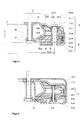
- Fig. 1 shows a known embodiment of a GleitFENK. Identical or similar features are identified in all figures with the same and similar reference numerals, regardless of whether the feature is known from the prior art or has come with the invention.
- the inner ring 3 consists of the support ring 3c and the support ring 3d.
- This rotary joint contains for sealing the cover 11, which also forms the storage space 10 and the labyrinth seal 9 and a lower sealing section 8. Also shown are the inner screws 7, which do not belong to the rotary joint, but are shown only for a better understanding of the function ,
- the inner ring 3 of the plain bearings can be produced from sheet metal.
- the sliding elements 2 are usually made of plastics with a low coefficient of friction. These elements, which belong to the prior art, are basically also present in the inventive rotary joint, but will not be further described.
- the pitch diameter 5a of the illustrated rotary joint is 550mm, the total height hges without the cover 11 is 54 mm.
- the sliding elements 2 are in one piece and have a recess 2e between the lower leg 2a and the upper leg 2b. This recess 2e makes it possible to design the sliding element 2 such that its joint area 2k serves as an elastic joint.
- the sliding track area 2f of the sliding element 2 can be pressed against the retaining track 3b of the inner ring 3 by means of springs which are not visible in this figure.
- the pressure springs are state of the art and are therefore not shown here but they play a role in the assembly of the inventive design and are therefore in the local Described in context and in FIG. 4 shown.
- this functionally related recess 2e has the disadvantage that the manufacture of the sliding elements becomes relatively complicated and expensive. For larger series, the sliding elements 2 are usually sprayed. The recess 2e requires forms with so-called "trains”. The disadvantages of this design are explained in the description of the prior art. Due to the basic shape of this bearing, in which the inner ring cross section on each side roughly the shape of a horizontal V and the sliding elements have the shape of a lying M this basic shape is also referred to as MV bearing (see Fig. 2 ).
- the closed circular shape of the rotary joint has the consequence that GleitFE16 in MV form not as easy as the MV linear guides according to Fig. 2 can be assembled, but that the outer ring 1 must consist of an outer ring lower part 1a and an outer ring upper part 1b and that the sliding elements 2 can not form a closed ring, but a segmented ring of a plurality of elements.
- the second requirement is not a practical disadvantage, because the Gleitcardtell for functional reasons anyway consists of several sliding elements 2. These are usually between six and thirty-two sliding elements 2. Only for applications with subordinate claims and small numbers is a Gleitcardtell according to published patent application EP 2 554 802 A2 ( Fig. 1 ) also with only 2 sliding appropriate.
- the M-shaped cross-section also requires, as described in the prior art, a complex mounting method
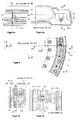
- Fig. 2 shows a rolling bearing linear guide in MV form.
- 16 means the M rail, 17 a simple V rail and 18 a double V rail.
- the linear guide contains as a bearing body cylindrical rollers 19. These cylindrical rollers 19 are held and guided in the angular cage 20.
- MV rails are finite stroke linear guide systems. Usually form two pairs of rails consisting of one M-rail 16 and a simple V-rail 17 together with the cylindrical rollers 19 and the angle cage 20 a complete MV linear guide. In special versions, especially at small distances between the two pairs of rails, the two inner simple V-rails 17 can also be combined to form a double V-rail 18.
- the two M-rails are attached to one component of a machine, for example on a machine frame, the two simple V-rails 17 on another machine part, for example on a carriage.
- the play or at best a slight bias of MV linear guides are adjusted by a rail, for example, an M-rail 16 is made or pressed transversely to the direction of movement.
- the GleitFE after Fig. 1 Corresponds in cross section to a roller bearing linear guide in MV form.
- the inner ring 3 of the rotary joint corresponds to a pair of simple V-rails 17, the sliding elements 2 and the outer ring 1 together correspond to the pair of M-rails 16 and the rolling elements 19.
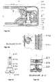
- Fig. 3 shows an embodiment of the inventive rotary joint in an axial cross-sectional view through the support sleeves 4 (section GG in Fig. 6 ).
- the inner ring 3 is here according to a variant of the rotary joint according to EP 2554 802 shown, in which it consists of the support ring 3c and the waisted support sleeves 6. It is similar to the rotary joint according to Fig. 1 configured and the same features are the same, but it has described improvements according to the invention described below.
- Each sliding element 2 consists of the lower part element 2c and the upper part element 2d.
- the upper part member 2d has a clamping board 2h, a bridge portion 2j, and an area with the sliding surface 2f.
- the bridge region 2j is elastic and therefore simultaneously serves as a joint.
- the two sliding element parts lower sub-element 2c and upper sub-element 2d are clamped in the cross-hatched printing area 2g by the outer ring upper part 1b and the outer ring lower part 1a by means of the screws 5.
- the outer ring upper part 1b Before the bracing, there is a gap between the upper end surface 4a of the support sleeve 4 and the horizontal portion 1c of the outer ring upper 1b.
- the outer ring upper part 1b first presses only on the cross-hatched pressure region 2g of the two sliding element parts, which extends over the upper part element 2d and the lower part element 2c.
- Fig. 4 shows an embodiment of the inventive rotary joint with a system for connecting the sub-elements 2c and 2d and for biasing the rotary joint in an axial cross-sectional view through the spring assembly 14 (section FF in Fig. 6 ).
- the screw 13 serves at the same time for connecting the upper sub-element 2 d with the lower sub-element 2 c to a sliding member 2 and as a means for continuously adjusting the biasing force on the rotary joint.
- the biasing force is generated by the spring assembly 14 and transmitted via the nut 15 and the biasing screw 13 to the upper sub-element 2 d.
- This bolted connection allows the preload force of each slewing ring to be optimally matched to the specific requirements of future use.
- the nut 15 is secured in the groove for sliding block 2y against rotation.
- the two sub-elements are first connected to the complete sliding element 2 and then placed around the inner ring 3.
- a sliding element 2 by means of the snap connection 12 according to the FIGS. 5 to 8 attached to the growing chain of sliding elements 2 and connected at the end the initially open C to a closed ring.
- the outer ring upper part 1b is placed over the assembly group consisting of inner ring 3 and sliding elements 2 and placed on this whole assembly group upside down.
- the support sleeves 4 ( Fig. 3 ) and the outer ring lower part 1a placed.
- the complete slewing connection is finished with 3 or 4 screws 5 ( Fig. 3 ) for storage and transport.
- Fig. 5 shows an embodiment of the inventive rotary joint with an additional functional element.
- the Fig. 5 shows one next to each other (right, in Fig. 5b , shown) radial and one (left, in Fig. 5a , shown) tangential sectional view through the connecting portion of two adjacent sliding elements 2 with an embodiment of the connection system.
- Add to that with the Fig. 6 a sectional view in a plane perpendicular to the axis of rotation with the connection system according to Fig. 5 consisting of pin and T-hole.
- a connection system in the form of a snap connection 12 is integrated, which allows the mating of the individual sliding elements 2 to form a closed ring.
- the assembly of the rotary joint is much easier, whereby the assembly time is reduced and the entire assembly is cheaper.
- the cuts of Fig. 5 show the rotary joint approximately on a scale of 1: 1.4.
- the sectional plane of the representation on the left lies tangentially parallel to the z-axis, that on the right is a radial xz-plane. This radial section runs in the gap between two elements.
- she is in FIG. 7 enlarged on a scale of 2: 1 (especially in comparison to the illustrations of the Fig. 5 ).
- connection system can also be realized by using two types of sliding elements. One type then contains a socket at each end and the other type has a plug at each end.
- connection components of the connection system are integrally integrated into the sliding elements 2.
- Fig. 6 is a horizontal partial section through an inventive rotary joint.
- the sectioning CC is in Fig. 5 specified.
- FIG. 6 are also called the axes.
- Fig. 7 shows the in the FIGS. 5 and 6 roughly described embodiment of a connection system in detail, wherein the sectional view of Fig. 7a (left), from the representation of the Fig. 5a (left), along the line DD results.
- the presentation of the Fig. 7b (right) is a sectional view of the Fig. 7a (left), resulting from the representation along the line EE results.
- each lower sub-element 2c has at one end in the circumferential direction a connecting pin 21 and at the other end a T-slot 2q.
- the diameter of the pin head 2n and the width of the groove-undercut 2s are greater than the associated diameter of the pin neck 2m and greater than the width of Nuthalses 2r.
- the pin head 2n can be pushed through the groove neck 2r into the groove-undercut 2s.
- the connecting pin 21 spring back into its original shape.
- the sliding elements 2 are expediently already according to the description Fig. 4 connected by means of the biasing screws 13 and the nut 15 to a mounting group.
- the components are thus provided at each free end of each sub-element 2c and 2d in the circumferential direction to be connectable with complementary components of the adjacent sub-element.
- the basic principle of the snap connection is the mushroom-shaped pin with a complementary undercut recess.
- the center of the connecting pin 21 in the parting plane 2w of the injection molding tool For manufacturing reasons, the center of the connecting pin 21 in the parting plane 2w of the injection molding tool. For the same reason, no bore is provided at the other end of the lower subelement 2c, but only a T-groove 2q which is U-shaped in section E-E.
- the sliding elements are connected only in the radial and tangential direction and in an axial direction.
- a closing cam 2t is attached to the upper part element 2d.
- the snap connection 12 fixes the adjacent sliding elements in all directions.
- the snap connections 12 have so much game that the still c-shaped ring open the sliding elements for insertion of the last sliding element can be opened slightly.
- Fig. 8 shows a rotary joint with a similar connection system for the sliding elements 2 as the Figs. 5-7 according to a further embodiment of the invention.
- the three individual representations are shown as sections along the lines AA ( Fig. 8c ), BB ( Fig. 8a ) and CC ( Fig. 8b ) in this Fig. 8 , It also consists of two connecting pins 2 1 and two T-slots 2q per slider.
- Both the lower one Sub-element 2c as the upper sub-element 2d each contain at one end a connecting pin 2 1 and at the other end a T-slot 2q.
- connection system in the lower subelement 2c is recessed below the lower surface of the recess 2e in the material of the subelement, while in the upper subelement 2d the molded spigot projects into this recess, since the overall height of the upper subelement 2d in the illustrated embodiment is smaller than the necessary Overall height for the tongue and groove connection is. Of course, this can also be provided vice versa.
- connection system is provided at a radial distance from the center of the bearing, which is smaller than the center distance of the support sleeves 4. Since the connection of the individual partial elements 2c or 2d achieved by the connection system has clearance, the choice of the radius in the upper or lower partial element 2c or 2d can be different and can be directed in particular from a spatial point of view. In particular, the connection systems can be provided at different radii.
- each slider at each end of an outlet forming recess for example, according to the sectional view of the AA Fig. 8 with two flexible ends 2v provided therein, and the sliding members 2c and 2d, respectively, are interconnected by separate connecting pin members provided for each connection between two adjacent sliding members. These are then dumbbell-shaped with two thickenings at the opposite ends and a central portion of reduced diameter.
- Fig. 9 shows an alternative embodiment of the connection and biasing system according to Fig. 4 . Same or similar characteristics as those associated with the Fig. 4 have been described here, the same reference numerals have been obtained and will not be explained separately in the following. In many applications, the continuous adjustment of the biasing force, as in the embodiment according to Fig. 4 is provided, not necessary.
- connection system for the two sub-elements 2c and 2d which in turn can be carried out particularly low thanks to the two-part design of the sliding elements.
- This embodiment can be combined with the support sleeve 6 of the inner ring 3.
- the connecting pin 21 forms together with the biasing springs 14, a two-stage connection system for the sub-elements 2c, 2d in the form of a rotary closure.
- the connecting pin 21 is above key-like with two locking wings 21 a and provided in the middle with two positioning wings 21 b; He has about the shape of a key with 2 double beards.
- Fig. 10 shows an embodiment of the inventive rotary joint with a system for biasing the rotary joint in an axial cross-sectional view through the spring assembly 14.
- the screw 13 serves simultaneously for continuously adjusting the biasing force on the rotary joint and as a means for connecting the upper sub-element 2 d with the lower Sub-element 2c to a sliding element 2.
- the biasing force is generated by the spring assembly 14 and transmitted via the nut 15 and the biasing screw 13 to the upper sub-element 2d.
- This bolted connection allows the preload force of each slewing ring to be optimally matched to the specific requirements of future use.
- the nut 15 is poured into the hexagonal recess 14 d in the lower part element 2 c and thus secured against rotation.
- the securing part 14e adjoins the nut 15.
- the bore in this lot is a few tenths of a millimeter smaller than the outer diameter of the preloading screw 13.
- this securing part must be deformed.
- the sliding elements 2 can also be produced from plastic semi-finished products instead of being sprayed.
- the hexagonal recess 14d can be pulled to the end face of the lower part element 2c.
- the nut can then be pressed or glued and the preload screw secured with, for example, adhesives.
- the spring sleeve 14a is provided with a chamfer 14b Provided.
- This chamfer facilitates the positioning of the upper sub-element 2d in relation to the first sub-element 2c installed first and thus additionally contributes to the reduction of the assembly time.
Landscapes
- Engineering & Computer Science (AREA)
- General Engineering & Computer Science (AREA)
- Mechanical Engineering (AREA)
- Physics & Mathematics (AREA)
- Fluid Mechanics (AREA)
- Pivots And Pivotal Connections (AREA)
- Bearings For Parts Moving Linearly (AREA)
- Rolling Contact Bearings (AREA)
Applications Claiming Priority (1)
| Application Number | Priority Date | Filing Date | Title |
|---|---|---|---|
| CH2962014 | 2014-02-27 |
Publications (3)
| Publication Number | Publication Date |
|---|---|
| EP2913544A2 true EP2913544A2 (fr) | 2015-09-02 |
| EP2913544A3 EP2913544A3 (fr) | 2015-10-07 |
| EP2913544B1 EP2913544B1 (fr) | 2018-03-28 |
Family
ID=52630307
Family Applications (1)
| Application Number | Title | Priority Date | Filing Date |
|---|---|---|---|
| EP15405018.1A Not-in-force EP2913544B1 (fr) | 2014-02-27 | 2015-02-26 | Couronne d'orientation en Forme de palier lisse |
Country Status (1)
| Country | Link |
|---|---|
| EP (1) | EP2913544B1 (fr) |
Cited By (4)
| Publication number | Priority date | Publication date | Assignee | Title |
|---|---|---|---|---|
| EP3299645A1 (fr) * | 2016-09-26 | 2018-03-28 | Rudolf Gehring | Couronne d'oriontation à base depalier lisse avec structures d'entrainement |
| CN108393684A (zh) * | 2018-05-03 | 2018-08-14 | 华中科技大学无锡研究院 | 一种可调浮动装置 |
| US12240740B2 (en) | 2022-02-21 | 2025-03-04 | Kundel Industries, Inc. | Method and apparatus for operating a slew bearing |
| CN120715587A (zh) * | 2025-08-29 | 2025-09-30 | 湖南星创智能装备有限公司 | 一种关节轴承的装配装置、装配设备及方法 |
Citations (5)
| Publication number | Priority date | Publication date | Assignee | Title |
|---|---|---|---|---|
| FR972570A (fr) | 1948-09-29 | 1951-01-31 | Coussinet lisse | |
| CH459668A (de) | 1966-06-03 | 1968-07-15 | Skf Svenska Kullagerfab Ab | Axiales und radiales Gleitlager |
| CH691191A5 (de) | 2000-01-06 | 2001-05-15 | Rudolf Ing Htl Gehring | Drehverbindung auf Gleitlagerbasis. |
| US20120183246A1 (en) | 2009-09-29 | 2012-07-19 | Ntn Corporation | Sliding bearing |
| EP2554802A2 (fr) | 2011-08-04 | 2013-02-06 | Rudolf Gehring | Couronne d'orientation en forme de palier lisse |
Family Cites Families (4)
| Publication number | Priority date | Publication date | Assignee | Title |
|---|---|---|---|---|
| CH281535A (de) * | 1950-01-07 | 1952-03-15 | Keller Friedrich | Ringgleitlager. |
| DE102005047625A1 (de) * | 2005-10-05 | 2007-04-12 | Kurz Tribotechnik | Radialgleitlager |
| WO2010070450A2 (fr) * | 2008-12-15 | 2010-06-24 | Jochen Corts | Paliers composites segmentés et générateur éolien utilisant une combinaison pompe hydraulique/moteur |
| DE102011013692B4 (de) * | 2011-03-11 | 2015-06-18 | Voith Patent Gmbh | Lageranordnung zum Aufnehmen des Axialschubes einer Welle |
-
2015
- 2015-02-26 EP EP15405018.1A patent/EP2913544B1/fr not_active Not-in-force
Patent Citations (5)
| Publication number | Priority date | Publication date | Assignee | Title |
|---|---|---|---|---|
| FR972570A (fr) | 1948-09-29 | 1951-01-31 | Coussinet lisse | |
| CH459668A (de) | 1966-06-03 | 1968-07-15 | Skf Svenska Kullagerfab Ab | Axiales und radiales Gleitlager |
| CH691191A5 (de) | 2000-01-06 | 2001-05-15 | Rudolf Ing Htl Gehring | Drehverbindung auf Gleitlagerbasis. |
| US20120183246A1 (en) | 2009-09-29 | 2012-07-19 | Ntn Corporation | Sliding bearing |
| EP2554802A2 (fr) | 2011-08-04 | 2013-02-06 | Rudolf Gehring | Couronne d'orientation en forme de palier lisse |
Cited By (4)
| Publication number | Priority date | Publication date | Assignee | Title |
|---|---|---|---|---|
| EP3299645A1 (fr) * | 2016-09-26 | 2018-03-28 | Rudolf Gehring | Couronne d'oriontation à base depalier lisse avec structures d'entrainement |
| CN108393684A (zh) * | 2018-05-03 | 2018-08-14 | 华中科技大学无锡研究院 | 一种可调浮动装置 |
| US12240740B2 (en) | 2022-02-21 | 2025-03-04 | Kundel Industries, Inc. | Method and apparatus for operating a slew bearing |
| CN120715587A (zh) * | 2025-08-29 | 2025-09-30 | 湖南星创智能装备有限公司 | 一种关节轴承的装配装置、装配设备及方法 |
Also Published As
| Publication number | Publication date |
|---|---|
| EP2913544B1 (fr) | 2018-03-28 |
| EP2913544A3 (fr) | 2015-10-07 |
Similar Documents
| Publication | Publication Date | Title |
|---|---|---|
| DE3931397C2 (fr) | ||
| DE69002141T2 (de) | Untersetzungsmechanismus für ein Gelenk mit Spielausgleich, anwendbar insbesondere zum Verstellen verschiedener Teile eines Fahrzeugsitzes. | |
| EP0472167B1 (fr) | Palier à contact de roulement pour mouvement linéaire, soit des rouleaux guidés sur rails | |
| EP0211243B1 (fr) | Palier à roulement pour mouvements linéaires | |
| DE68904117T2 (de) | Kugelgelenk. | |
| DE3416207A1 (de) | Linear-kugellageranordnung | |
| DE3227902C2 (de) | Linearkugellagereinheit | |
| EP2426050B1 (fr) | Elément de coussinet d'un palier de gouvernail | |
| DE102011000769A1 (de) | Axial-Radialwälzlager, insbesondere für die Lagerung von Rotorblättern an einer Windkraftanlage | |
| CH660215A5 (de) | Rollenumlauflager. | |
| EP2913544B1 (fr) | Couronne d'orientation en Forme de palier lisse | |
| DE3843096A1 (de) | Befestigungseinrichtung fuer verkleidungen | |
| DE102016216286A1 (de) | Segmentierter Wälzlagerkäfig und Käfigsegment zur Bildung desselben | |
| DE3304641A1 (de) | Waelzkoerpergelagerte laengsfuehrung fuer unbegrenzte schiebewege | |
| AT400881B (de) | Spindelhubgetriebe | |
| DE3620571A1 (de) | Waelzlager fuer linearbewegungen | |
| DE102011003376B4 (de) | Segmentkäfig | |
| WO2008043531A1 (fr) | Moule à injection pour réaliser des unités en forme de plaques faites d'une plaque et d'un cadre | |
| DE3910457A1 (de) | Linearkugelbuechse | |
| EP2649331B1 (fr) | Roulement radial avec organes d'espacement libres entre les éléments roulants et procédé d'assemblage du roulement | |
| DE3418621A1 (de) | Waelzlager | |
| WO2004025124A1 (fr) | Stator pour pompe a vis sans fin excentrique | |
| DE3512858A1 (de) | Linearkugellager stichwort: radial-compact-fuehrung | |
| DE1956836A1 (de) | Waelzlageranordnung und Verfahren zu dessen Herstellung | |
| DE102018127682B4 (de) | Anordnung mit einer Justagevorrichtung zur Lageeinstellung zweier miteinander verbundener Bauteile |
Legal Events
| Date | Code | Title | Description |
|---|---|---|---|
| PUAI | Public reference made under article 153(3) epc to a published international application that has entered the european phase |
Free format text: ORIGINAL CODE: 0009012 |
|
| AK | Designated contracting states |
Kind code of ref document: A2 Designated state(s): AL AT BE BG CH CY CZ DE DK EE ES FI FR GB GR HR HU IE IS IT LI LT LU LV MC MK MT NL NO PL PT RO RS SE SI SK SM TR |
|
| AX | Request for extension of the european patent |
Extension state: BA ME |
|
| PUAL | Search report despatched |
Free format text: ORIGINAL CODE: 0009013 |
|
| AK | Designated contracting states |
Kind code of ref document: A3 Designated state(s): AL AT BE BG CH CY CZ DE DK EE ES FI FR GB GR HR HU IE IS IT LI LT LU LV MC MK MT NL NO PL PT RO RS SE SI SK SM TR |
|
| AX | Request for extension of the european patent |
Extension state: BA ME |
|
| RIC1 | Information provided on ipc code assigned before grant |
Ipc: F16C 35/02 20060101ALI20150828BHEP Ipc: F16C 25/02 20060101ALI20150828BHEP Ipc: F16C 17/10 20060101AFI20150828BHEP Ipc: F16C 33/04 20060101ALI20150828BHEP Ipc: F16C 33/20 20060101ALN20150828BHEP Ipc: F16C 43/02 20060101ALI20150828BHEP Ipc: F16C 33/26 20060101ALI20150828BHEP |
|
| 17P | Request for examination filed |
Effective date: 20160225 |
|
| RBV | Designated contracting states (corrected) |
Designated state(s): AL AT BE BG CH CY CZ DE DK EE ES FI FR GB GR HR HU IE IS IT LI LT LU LV MC MK MT NL NO PL PT RO RS SE SI SK SM TR |
|
| 17Q | First examination report despatched |
Effective date: 20160810 |
|
| STAA | Information on the status of an ep patent application or granted ep patent |
Free format text: STATUS: EXAMINATION IS IN PROGRESS |
|
| RIC1 | Information provided on ipc code assigned before grant |
Ipc: F16C 33/04 20060101ALI20171003BHEP Ipc: F16C 17/10 20060101ALI20171003BHEP Ipc: F16C 25/02 20060101ALI20171003BHEP Ipc: F16C 33/20 20060101ALN20171003BHEP Ipc: F16C 11/06 20060101AFI20171003BHEP Ipc: F16C 43/02 20060101ALI20171003BHEP |
|
| REG | Reference to a national code |
Ref country code: DE Ref legal event code: R079 Ref document number: 502015003606 Country of ref document: DE Free format text: PREVIOUS MAIN CLASS: F16C0017100000 Ipc: F16C0011060000 |
|
| GRAP | Despatch of communication of intention to grant a patent |
Free format text: ORIGINAL CODE: EPIDOSNIGR1 |
|
| STAA | Information on the status of an ep patent application or granted ep patent |
Free format text: STATUS: GRANT OF PATENT IS INTENDED |
|
| RIC1 | Information provided on ipc code assigned before grant |
Ipc: F16C 33/20 20060101ALN20171107BHEP Ipc: F16C 25/02 20060101ALI20171107BHEP Ipc: F16C 33/04 20060101ALI20171107BHEP Ipc: F16C 43/02 20060101ALI20171107BHEP Ipc: F16C 17/10 20060101ALI20171107BHEP Ipc: F16C 11/06 20060101AFI20171107BHEP |
|
| RIC1 | Information provided on ipc code assigned before grant |
Ipc: F16C 33/04 20060101ALI20171123BHEP Ipc: F16C 33/20 20060101ALN20171123BHEP Ipc: F16C 25/02 20060101ALI20171123BHEP Ipc: F16C 11/06 20060101AFI20171123BHEP Ipc: F16C 43/02 20060101ALI20171123BHEP Ipc: F16C 17/10 20060101ALI20171123BHEP |
|
| RIC1 | Information provided on ipc code assigned before grant |
Ipc: F16C 33/04 20060101ALI20171124BHEP Ipc: F16C 43/02 20060101ALI20171124BHEP Ipc: F16C 17/10 20060101ALI20171124BHEP Ipc: F16C 11/06 20060101AFI20171124BHEP Ipc: F16C 33/20 20060101ALN20171124BHEP Ipc: F16C 25/02 20060101ALI20171124BHEP |
|
| INTG | Intention to grant announced |
Effective date: 20171213 |
|
| GRAS | Grant fee paid |
Free format text: ORIGINAL CODE: EPIDOSNIGR3 |
|
| GRAA | (expected) grant |
Free format text: ORIGINAL CODE: 0009210 |
|
| STAA | Information on the status of an ep patent application or granted ep patent |
Free format text: STATUS: THE PATENT HAS BEEN GRANTED |
|
| AK | Designated contracting states |
Kind code of ref document: B1 Designated state(s): AL AT BE BG CH CY CZ DE DK EE ES FI FR GB GR HR HU IE IS IT LI LT LU LV MC MK MT NL NO PL PT RO RS SE SI SK SM TR |
|
| REG | Reference to a national code |
Ref country code: GB Ref legal event code: FG4D Free format text: NOT ENGLISH |
|
| REG | Reference to a national code |
Ref country code: CH Ref legal event code: EP |
|
| REG | Reference to a national code |
Ref country code: AT Ref legal event code: REF Ref document number: 983719 Country of ref document: AT Kind code of ref document: T Effective date: 20180415 |
|
| REG | Reference to a national code |
Ref country code: IE Ref legal event code: FG4D Free format text: LANGUAGE OF EP DOCUMENT: GERMAN |
|
| REG | Reference to a national code |
Ref country code: DE Ref legal event code: R096 Ref document number: 502015003606 Country of ref document: DE |
|
| PG25 | Lapsed in a contracting state [announced via postgrant information from national office to epo] |
Ref country code: FI Free format text: LAPSE BECAUSE OF FAILURE TO SUBMIT A TRANSLATION OF THE DESCRIPTION OR TO PAY THE FEE WITHIN THE PRESCRIBED TIME-LIMIT Effective date: 20180328 Ref country code: LT Free format text: LAPSE BECAUSE OF FAILURE TO SUBMIT A TRANSLATION OF THE DESCRIPTION OR TO PAY THE FEE WITHIN THE PRESCRIBED TIME-LIMIT Effective date: 20180328 Ref country code: NO Free format text: LAPSE BECAUSE OF FAILURE TO SUBMIT A TRANSLATION OF THE DESCRIPTION OR TO PAY THE FEE WITHIN THE PRESCRIBED TIME-LIMIT Effective date: 20180628 Ref country code: HR Free format text: LAPSE BECAUSE OF FAILURE TO SUBMIT A TRANSLATION OF THE DESCRIPTION OR TO PAY THE FEE WITHIN THE PRESCRIBED TIME-LIMIT Effective date: 20180328 |
|
| REG | Reference to a national code |
Ref country code: NL Ref legal event code: MP Effective date: 20180328 |
|
| REG | Reference to a national code |
Ref country code: LT Ref legal event code: MG4D |
|
| PG25 | Lapsed in a contracting state [announced via postgrant information from national office to epo] |
Ref country code: BG Free format text: LAPSE BECAUSE OF FAILURE TO SUBMIT A TRANSLATION OF THE DESCRIPTION OR TO PAY THE FEE WITHIN THE PRESCRIBED TIME-LIMIT Effective date: 20180628 Ref country code: RS Free format text: LAPSE BECAUSE OF FAILURE TO SUBMIT A TRANSLATION OF THE DESCRIPTION OR TO PAY THE FEE WITHIN THE PRESCRIBED TIME-LIMIT Effective date: 20180328 Ref country code: SE Free format text: LAPSE BECAUSE OF FAILURE TO SUBMIT A TRANSLATION OF THE DESCRIPTION OR TO PAY THE FEE WITHIN THE PRESCRIBED TIME-LIMIT Effective date: 20180328 Ref country code: LV Free format text: LAPSE BECAUSE OF FAILURE TO SUBMIT A TRANSLATION OF THE DESCRIPTION OR TO PAY THE FEE WITHIN THE PRESCRIBED TIME-LIMIT Effective date: 20180328 Ref country code: GR Free format text: LAPSE BECAUSE OF FAILURE TO SUBMIT A TRANSLATION OF THE DESCRIPTION OR TO PAY THE FEE WITHIN THE PRESCRIBED TIME-LIMIT Effective date: 20180629 |
|
| PG25 | Lapsed in a contracting state [announced via postgrant information from national office to epo] |
Ref country code: MT Free format text: LAPSE BECAUSE OF FAILURE TO SUBMIT A TRANSLATION OF THE DESCRIPTION OR TO PAY THE FEE WITHIN THE PRESCRIBED TIME-LIMIT Effective date: 20180328 |
|
| PG25 | Lapsed in a contracting state [announced via postgrant information from national office to epo] |
Ref country code: PL Free format text: LAPSE BECAUSE OF FAILURE TO SUBMIT A TRANSLATION OF THE DESCRIPTION OR TO PAY THE FEE WITHIN THE PRESCRIBED TIME-LIMIT Effective date: 20180328 Ref country code: EE Free format text: LAPSE BECAUSE OF FAILURE TO SUBMIT A TRANSLATION OF THE DESCRIPTION OR TO PAY THE FEE WITHIN THE PRESCRIBED TIME-LIMIT Effective date: 20180328 Ref country code: ES Free format text: LAPSE BECAUSE OF FAILURE TO SUBMIT A TRANSLATION OF THE DESCRIPTION OR TO PAY THE FEE WITHIN THE PRESCRIBED TIME-LIMIT Effective date: 20180328 Ref country code: RO Free format text: LAPSE BECAUSE OF FAILURE TO SUBMIT A TRANSLATION OF THE DESCRIPTION OR TO PAY THE FEE WITHIN THE PRESCRIBED TIME-LIMIT Effective date: 20180328 Ref country code: NL Free format text: LAPSE BECAUSE OF FAILURE TO SUBMIT A TRANSLATION OF THE DESCRIPTION OR TO PAY THE FEE WITHIN THE PRESCRIBED TIME-LIMIT Effective date: 20180328 Ref country code: AL Free format text: LAPSE BECAUSE OF FAILURE TO SUBMIT A TRANSLATION OF THE DESCRIPTION OR TO PAY THE FEE WITHIN THE PRESCRIBED TIME-LIMIT Effective date: 20180328 |
|
| PG25 | Lapsed in a contracting state [announced via postgrant information from national office to epo] |
Ref country code: SK Free format text: LAPSE BECAUSE OF FAILURE TO SUBMIT A TRANSLATION OF THE DESCRIPTION OR TO PAY THE FEE WITHIN THE PRESCRIBED TIME-LIMIT Effective date: 20180328 Ref country code: SM Free format text: LAPSE BECAUSE OF FAILURE TO SUBMIT A TRANSLATION OF THE DESCRIPTION OR TO PAY THE FEE WITHIN THE PRESCRIBED TIME-LIMIT Effective date: 20180328 Ref country code: CZ Free format text: LAPSE BECAUSE OF FAILURE TO SUBMIT A TRANSLATION OF THE DESCRIPTION OR TO PAY THE FEE WITHIN THE PRESCRIBED TIME-LIMIT Effective date: 20180328 |
|
| PG25 | Lapsed in a contracting state [announced via postgrant information from national office to epo] |
Ref country code: PT Free format text: LAPSE BECAUSE OF FAILURE TO SUBMIT A TRANSLATION OF THE DESCRIPTION OR TO PAY THE FEE WITHIN THE PRESCRIBED TIME-LIMIT Effective date: 20180730 |
|
| REG | Reference to a national code |
Ref country code: DE Ref legal event code: R097 Ref document number: 502015003606 Country of ref document: DE |
|
| PG25 | Lapsed in a contracting state [announced via postgrant information from national office to epo] |
Ref country code: DK Free format text: LAPSE BECAUSE OF FAILURE TO SUBMIT A TRANSLATION OF THE DESCRIPTION OR TO PAY THE FEE WITHIN THE PRESCRIBED TIME-LIMIT Effective date: 20180328 |
|
| PLBE | No opposition filed within time limit |
Free format text: ORIGINAL CODE: 0009261 |
|
| STAA | Information on the status of an ep patent application or granted ep patent |
Free format text: STATUS: NO OPPOSITION FILED WITHIN TIME LIMIT |
|
| PG25 | Lapsed in a contracting state [announced via postgrant information from national office to epo] |
Ref country code: IT Free format text: LAPSE BECAUSE OF FAILURE TO SUBMIT A TRANSLATION OF THE DESCRIPTION OR TO PAY THE FEE WITHIN THE PRESCRIBED TIME-LIMIT Effective date: 20180328 |
|
| 26N | No opposition filed |
Effective date: 20190103 |
|
| PGFP | Annual fee paid to national office [announced via postgrant information from national office to epo] |
Ref country code: FR Payment date: 20190329 Year of fee payment: 5 Ref country code: GB Payment date: 20190325 Year of fee payment: 5 |
|
| PG25 | Lapsed in a contracting state [announced via postgrant information from national office to epo] |
Ref country code: SI Free format text: LAPSE BECAUSE OF FAILURE TO SUBMIT A TRANSLATION OF THE DESCRIPTION OR TO PAY THE FEE WITHIN THE PRESCRIBED TIME-LIMIT Effective date: 20180328 |
|
| PG25 | Lapsed in a contracting state [announced via postgrant information from national office to epo] |
Ref country code: LU Free format text: LAPSE BECAUSE OF NON-PAYMENT OF DUE FEES Effective date: 20190226 Ref country code: MC Free format text: LAPSE BECAUSE OF FAILURE TO SUBMIT A TRANSLATION OF THE DESCRIPTION OR TO PAY THE FEE WITHIN THE PRESCRIBED TIME-LIMIT Effective date: 20180328 |
|
| REG | Reference to a national code |
Ref country code: BE Ref legal event code: MM Effective date: 20190228 |
|
| REG | Reference to a national code |
Ref country code: IE Ref legal event code: MM4A |
|
| PG25 | Lapsed in a contracting state [announced via postgrant information from national office to epo] |
Ref country code: IE Free format text: LAPSE BECAUSE OF NON-PAYMENT OF DUE FEES Effective date: 20190226 |
|
| PG25 | Lapsed in a contracting state [announced via postgrant information from national office to epo] |
Ref country code: BE Free format text: LAPSE BECAUSE OF NON-PAYMENT OF DUE FEES Effective date: 20190228 |
|
| PG25 | Lapsed in a contracting state [announced via postgrant information from national office to epo] |
Ref country code: TR Free format text: LAPSE BECAUSE OF FAILURE TO SUBMIT A TRANSLATION OF THE DESCRIPTION OR TO PAY THE FEE WITHIN THE PRESCRIBED TIME-LIMIT Effective date: 20180328 |
|
| GBPC | Gb: european patent ceased through non-payment of renewal fee |
Effective date: 20200226 |
|
| PG25 | Lapsed in a contracting state [announced via postgrant information from national office to epo] |
Ref country code: GB Free format text: LAPSE BECAUSE OF NON-PAYMENT OF DUE FEES Effective date: 20200226 |
|
| REG | Reference to a national code |
Ref country code: AT Ref legal event code: MM01 Ref document number: 983719 Country of ref document: AT Kind code of ref document: T Effective date: 20200226 |
|
| PG25 | Lapsed in a contracting state [announced via postgrant information from national office to epo] |
Ref country code: CY Free format text: LAPSE BECAUSE OF FAILURE TO SUBMIT A TRANSLATION OF THE DESCRIPTION OR TO PAY THE FEE WITHIN THE PRESCRIBED TIME-LIMIT Effective date: 20180328 Ref country code: AT Free format text: LAPSE BECAUSE OF NON-PAYMENT OF DUE FEES Effective date: 20200226 |
|
| PGFP | Annual fee paid to national office [announced via postgrant information from national office to epo] |
Ref country code: DE Payment date: 20210225 Year of fee payment: 7 |
|
| PG25 | Lapsed in a contracting state [announced via postgrant information from national office to epo] |
Ref country code: IS Free format text: LAPSE BECAUSE OF FAILURE TO SUBMIT A TRANSLATION OF THE DESCRIPTION OR TO PAY THE FEE WITHIN THE PRESCRIBED TIME-LIMIT Effective date: 20180728 |
|
| PG25 | Lapsed in a contracting state [announced via postgrant information from national office to epo] |
Ref country code: HU Free format text: LAPSE BECAUSE OF FAILURE TO SUBMIT A TRANSLATION OF THE DESCRIPTION OR TO PAY THE FEE WITHIN THE PRESCRIBED TIME-LIMIT; INVALID AB INITIO Effective date: 20150226 |
|
| PG25 | Lapsed in a contracting state [announced via postgrant information from national office to epo] |
Ref country code: FR Free format text: LAPSE BECAUSE OF NON-PAYMENT OF DUE FEES Effective date: 20210228 |
|
| PGFP | Annual fee paid to national office [announced via postgrant information from national office to epo] |
Ref country code: CH Payment date: 20220107 Year of fee payment: 8 |
|
| PG25 | Lapsed in a contracting state [announced via postgrant information from national office to epo] |
Ref country code: MK Free format text: LAPSE BECAUSE OF FAILURE TO SUBMIT A TRANSLATION OF THE DESCRIPTION OR TO PAY THE FEE WITHIN THE PRESCRIBED TIME-LIMIT Effective date: 20180328 |
|
| REG | Reference to a national code |
Ref country code: DE Ref legal event code: R119 Ref document number: 502015003606 Country of ref document: DE |
|
| PG25 | Lapsed in a contracting state [announced via postgrant information from national office to epo] |
Ref country code: DE Free format text: LAPSE BECAUSE OF NON-PAYMENT OF DUE FEES Effective date: 20220901 |
|
| REG | Reference to a national code |
Ref country code: CH Ref legal event code: PL |
|
| PG25 | Lapsed in a contracting state [announced via postgrant information from national office to epo] |
Ref country code: LI Free format text: LAPSE BECAUSE OF NON-PAYMENT OF DUE FEES Effective date: 20230228 Ref country code: CH Free format text: LAPSE BECAUSE OF NON-PAYMENT OF DUE FEES Effective date: 20230228 |