EP2913571B1 - Verteilerventil - Google Patents
Verteilerventil Download PDFInfo
- Publication number
- EP2913571B1 EP2913571B1 EP15000470.3A EP15000470A EP2913571B1 EP 2913571 B1 EP2913571 B1 EP 2913571B1 EP 15000470 A EP15000470 A EP 15000470A EP 2913571 B1 EP2913571 B1 EP 2913571B1
- Authority
- EP
- European Patent Office
- Prior art keywords
- distribution valve
- valve according
- valve
- motor
- closure element
- Prior art date
- Legal status (The legal status is an assumption and is not a legal conclusion. Google has not performed a legal analysis and makes no representation as to the accuracy of the status listed.)
- Active
Links
Images


Classifications
-
- F—MECHANICAL ENGINEERING; LIGHTING; HEATING; WEAPONS; BLASTING
- F16—ENGINEERING ELEMENTS AND UNITS; GENERAL MEASURES FOR PRODUCING AND MAINTAINING EFFECTIVE FUNCTIONING OF MACHINES OR INSTALLATIONS; THERMAL INSULATION IN GENERAL
- F16K—VALVES; TAPS; COCKS; ACTUATING-FLOATS; DEVICES FOR VENTING OR AERATING
- F16K31/00—Actuating devices; Operating means; Releasing devices
- F16K31/02—Actuating devices; Operating means; Releasing devices electric; magnetic
- F16K31/04—Actuating devices; Operating means; Releasing devices electric; magnetic using a motor
- F16K31/05—Actuating devices; Operating means; Releasing devices electric; magnetic using a motor specially adapted for operating hand-operated valves or for combined motor and hand operation
Definitions
- the invention relates to a distribution valve, in particular but not exclusively for the regulation of the coolant supply to tools on injection molding machines.
- the cooling liquid is fed in and out centrally via distributors, and the distribution to the individual circuits from there by means of manual valves has hitherto been regulated manually.
- a generic valve according to the features defined in the preamble of claim 1 is for example in CH-A-231,313 shown.
- the invention is therefore based on the object to remedy this situation.
- This object is achieved by a distribution valve with the features of claim 1.
- valve member actuating the closure element is guided in a sleeve positioned in a constant position relative to the valve seat.
- On the sleeve is in turn slide-movable and also sleeve-like a sliding housing part connected, via which the position of the drive motor is changeable and can be locked in different positions.
- the closure element can also be lifted off the valve seat and the valve is in an open position even when the engine has failed or is not activated by lifting the engine and thus via the valve stem be transferred.
- This change in position of the motor via the displaceable housing part is preferably carried out by hand, so that no additional motor drive is needed.
- An embodiment according to the invention provides a locking element, which is connected to the sleeve at least indirectly, for example via a mounting flange, and can fix or lock the displaceable housing part in different positions.
- a closed position but also an open position can be defined. This can preferably be done via a displaceability of the housing part at least in one direction limiting and thus securing spacer or spacer elements, which may have a pronounced distance level.
- an intermediate position e.g. be provided fixed "semi-closed".
- the protection class IP54 or higher is often required, for which purpose the drive motor must be encapsulated.
- the distribution valve is therefore preferably provided with a drive housing.
- the drive housing is preferably provided with recesses or indentations and shaped such that the locking element can be operated from above.
- the ability to mount or dismount the entire distribution valve from above is advantageous, so that the shape of the drive housing preferably also leaves free space to solve any mounting screws for the valve on a manifold or manifold memory from above and set.
- the displaceable housing part is designed to be rotatable, preferably by 360 °.
- linear stepper motors are used for the valves according to the invention. These perform a calibration drive after installation and after each power interruption in order to safely find the zero point and thus ensure a high positioning accuracy.
- the spindle moves a) in the direction of the valve seat as a reference point or b) a small defined distance from the valve seat and then back against the valve seat (as a defined resistance).
- the valve according to the invention is preferably structurally secured with a sealing mechanism against uncontrolled leakage of medium. This can preferably be done by the valve rod is connected to the closure element by a Leerhub Ou (the calibration) against each other axially displaceable and biased by a spring. The bias by the spring thereby causes the closure element always remains on the valve seat, even if the valve stem is raised to perform the calibration drive.
- connection of the valve rod with the closure element may preferably be effected via a pinning which extends through the valve rod and a shaft portion of the closure element.
- the connecting pin is fixed in one of the two parts to be joined and held in the other with the required clearance.
- the pinning is preferably designed so that the sealing force in the closed valve position is not transmitted via the cylinder pin, but directly from the valve stem to the closure element.
- the game is composed of the idle stroke and an additional residual air gap. During the calibration run, the idle stroke then compensates for the movement of the motor.
- the sealing force of the closure element on the valve seat is supported on the one hand by the spring and on the other hand ensured by the applied pressure difference of the operating medium on both sides.
- FIG. 1 a distributor valve according to the invention is shown on a section of a tank profile or distribution tank 1, namely in FIG Fig. 1 a in a perspective view, in Fig. 1b in a side view, in Fig. 1c in a 90 ° rotated side view, in Fig. 1d in a section towards BB through Fig. 1c and in Fig. 1e in a section towards AA through Fig. 1 b.
- the valve has a drive motor 2, which is encapsulated in a drive housing 3.
- the motor acts on a valve rod 4, often also called valve spindle, whereby it can be moved up and down in the direction of the longitudinal axis 5.
- the valve rod 4 carries at its front end a closure element 6, often referred to as a valve plate.
- the closure element 6 has an integrated seal and a control cone 7 and can thus seal a valve seat 8 formed in the distribution tank 1 so that no medium can flow from the interior 9 of the distribution tank to the outlet 11.
- a pressure element 12 here in the form of a spiral spring, is provided on the valve rod 4, which presses the closure element 6 against the valve seat 8 via the valve rod 4.
- the valve rod 4 By energizing the motor 2, the valve rod 4 can be pulled against the force of the pressure element 12 upwards, so that the closure element 6 lifts off the valve seat 8 and opens the valve.
- the valve rod 4 is guided in terms of their linear movement in a sleeve 14.
- a housing part 13 is guided, which is fixedly connected to the drive motor 2 - here via the drive housing 3. If the housing part 13 is displaced upward relative to the sleeve 14 fixed to the distributor tank 1, the motor will also become weaker displaced above and thus the valve rod 4, so that the closure element 6 lifts off the valve seat 8 and the valve is transferred to an open position.
- an in Fig. 1e shown locking element 15 used in Fig. 2 is explained in more detail on the basis of the different valve positions.
- Fig. 2 show different valve positions A to E from the closed state with no current supplied motor A to the fixed in an open position state E at also powered up motor.
- a screw 17 is released via an Allen key 16 attached from above, which fixes the here bow-shaped locking element 15 in the respectively selected position.
- position B the released locking element 15 is pivoted about a fixed pivot axis 18 to the outside and thus gives a small flange 23 (see also Fig. 1 d) of the housing part 13 free.
- the drive motor with the drive housing 3 is lifted or pulled upwards over the housing part 13, thereby manually opening the valve.
- the bow-shaped locking element 15 has two spacer stages 15.1 and 15.2, wherein the one 15.1 fixes the valve in the closed position, while the other 15.2 serves to fix the open position.
- the valve may also be provided in an embodiment not shown here with a multi-stage locking element, for example, still allows the fixation of a semi-open position.
- Fig. 2 also clearly shows that this is 360 ° rotatable drive housing 3 space-optimized with various recesses or indentations, on the one hand for manual operation, the preferably captive designed screw 17 can be solved and tightened and on the other hand, the complete assembly and disassembly of the valve From above it is possible by loosening or fastening screws 24, which preferably fix the sleeve 14 via a fastening flange 29 formed on it and a fixing plate 30 on the distributor tank 1. Also for space optimization is a in Fig. 1c . 2a and 2b recognizable cable entry 19 (with not shown cable) respectively at the bottom of the drive housing. 3
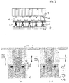
- Fig. 3 is similar to a valve chain Fig. 2 but shown with cut distribution tank 1. Only the middle valve is open, while the two outer valves are closed.
- the Fig. 3b and 3c are detail enlargements and show in Fig. 3b the closed valve at rest and in Fig. 3c the valve during a calibration run while still remaining in a closed position.
- the closure element 6 is connected via a shaft part 26 with the valve rod 4 in the direction of the longitudinal axis 5 slidably.
- the shaft part 26 is guided in a blind hole of the valve rod 4.
- a spring 27 which biases the closure element 6 against the valve rod 4.
- connection between closure element 6 and valve rod 4 is secured via a pinning with a connecting pin 28, which extends through both the shaft portion 26 of the closure element 6 and through the valve rod 4 therethrough.
- the connecting pin 28 is held here in the shaft part 26, but has in the opening of the valve rod 4 game, so that the shaft member 26 in the blind hole of the valve rod 4 can move up and down.
- the total clearance S is made up of the height of an idle stroke LH for the calibra- tion travel and the height of a residual air gap RL, which ensures that the valve during a calibration travel ( Fig. 3c ) via the force of the spring 27 (possibly supported by the pressure difference of acting on the upper side 6 'of the closure element 6 and the control cone 7 media) remains closed.
- the spring force is therefore to be selected accordingly taking into account the pressure difference of the operating medium.
- the above-described sealing mechanism can also be omitted and the valve rod (4) with the closure element (6) as a component in particular in one piece, running.
- the distribution valve according to the invention is extremely versatile and allows independent of the drive motor, the fixation of an open or a closed position. It is mounted in the illustrated embodiment in a small space from above and allows for secure closure the use of linear stepper motors that need for their precise function a calibration drive.
Landscapes
- Engineering & Computer Science (AREA)
- General Engineering & Computer Science (AREA)
- Mechanical Engineering (AREA)
- Mechanically-Actuated Valves (AREA)
- Lift Valve (AREA)
Description
- Die Erfindung betrifft ein Verteilerventil, insbesondere aber nicht ausschließlich für die Regelung der Kühlflüssigkeitszufuhr zu Werkzeugen an Spritzgießmaschinen. Die Kühlflüssigkeit wird dabei über Verteiler zentral zu- und abgeführt und die Verteilung auf die Einzelkreisläufe von dort mittels Handventilen bislang noch manuell eingeregelt.
- Ein gattungsgemässes Ventil entsprechend den im Oberbegriff von Anspruch 1 definierten Merkmalen ist beispielsweise in
CH-A-231 313 - Es sind auch motorisch angetriebene Verteilerventile mit den Merkmalen des Anspruchs 1 bekannt, die aber bisher für diese Zwecke nicht eingesetzt wurden, da sie diverse Nachteile aufweisen. Im Gegensatz zu handbetätigten Ventilen ist es bei den vorbekannten motorischen Ventilen z. B. nachteilig, dass bei nicht aktivem Motor nur eine Position des Ventils möglich ist.
- Der Erfindung liegt daher die Aufgabe zugrunde, hier Abhilfe zu schaffen. Diese Aufgabe wird erfindungsgemäß durch ein Verteilerventil mit den Merkmalen des Anspruchs 1 gelöst.
- Die das Verschlusselement betätigende Ventilstange ist dabei in einer gegenüber dem Ventilsitz gleichbleibend positionierten Hülse geführt. An der Hülse ist wiederum schiebebeweglich und ebenfalls hülsenartig ein verschiebbarer Gehäuseteil angebunden, über den die Position des Antriebsmotors veränderbar und in verschiedenen Positionen arretierbar ist. Dadurch kann auch bei ausgefallenem bzw. nicht aktivem Motor über ein Abheben des Motors und damit über die Ventilstange ebenfalls das Verschlusselement vom Ventilsitz abgehoben und das Ventil in eine Offen-Position überführt werden. Diese Positionsveränderung des Motors über das verschiebbare Gehäuseteil ist bevorzugt von Hand vorzunehmen, so dass kein zusätzlicher motorischer Antrieb benötigt wird.
- Eine erfindungsgemäße Ausgestaltung sieht ein Arretierelement vor, das mit der Hülse zumindest mittelbar, beispielsweise über einen Befestigungsflansch, verbunden ist und das verschiebliche Gehäuseteil in verschiedenen Positionen festlegen bzw. arretieren kann. So kann beispielsweise eine Geschlossen-Position aber auch eine Offen-Position festgelegt werden. Dies kann vorzugsweise über eine Verschiebbarkeit des Gehäuseteils zumindest in eine Richtung begrenzendes und damit sicherndes Abstandselement bzw. Abstandselemente geschehen, welches eine dazu ausgeprägte Abstandsstufe aufweisen kann. Es ist auch möglich, das Arretierelement mehrstufig auszubilden und so mehrere Positionen des Antriebsmotors und damit des Ventils festzulegen. Unter anderem kann neben einer Offen- und einer Geschlossen-Position daher auch eine Zwischenposition, z.B. "halb geschlossen" festlegbar vorgesehen werden.
- Für die erfindungsgemäßen Ventile wird oftmals die Schutzklasse IP54 oder höher gefordert, wozu der Antriebsmotor gekapselt werden muss. Das Verteilerventil ist daher bevorzugt mit einem Antriebsgehäuse vorzusehen. Um trotzdem eine geringe Baugröße zu erreichen und mehrere Ventile zueinander eng benachbart anordnen zu können, ist das Antriebsgehäuse vorzugsweise derart mit Aussparungen bzw. Einbuchtungen versehen und geformt, dass das Arretierelement von oben bedienbar ist. Auch die Möglichkeit, das gesamte Verteilerventil von oben montieren bzw. demontieren zu können, ist vorteilhaft, so dass die Form des Antriebsgehäuses bevorzugt auch Freiräume lässt, eventuelle Montageschrauben für das Ventil auf einem Verteilerrohr oder Verteilerspeicher von oben lösen und festlegen zu können. Insbesondere ist es vorteilhaft, wenn das verschiebbare Gehäuseteil drehbar, vorzugsweise um 360°, ausgestaltet ist.
- Zur Platzersparnis trägt auch bei, das Antriebsgehäuse mit einer Kabeleinführung von der Unter- oder Oberseite aus zu versehen, damit kein Kabel seitlich heraustreten muss und eventuell den Einbau und andere Ventile behindert.
- Für die erfindungsgemäßen Ventile sind bevorzugt lineare Schrittmotoren einzusetzen. Diese führen nach dem Einbau und nach jeder Stromunterbrechung eine Kalibrierfahrt durch, um sicher den Nullpunkt zu finden und somit eine hohe Stellgenauigkeit zu gewährleisten. Je nachdem wie die Motoransteuerung programmiert wird, fährt die Spindel a) in Richtung des Ventilsitzes als Referenzpunkt oder b) eine kleine definierte Wegstrecke vom Ventilsitz aus weg, um dann wieder gegen den Ventilsitz (als definierten Widerstand) anzufahren.
- Befindet sich im Fall b) in dem Sammelbehälter bzw. dem Verteiler während der Kalibierfahrt noch Medium und/oder steht der Behälter unter Druck, kann bei einer Kalibrierfahrt eines eigentlich geschlossenen Ventils ungewollt und unkontrolliert Medium über den Ausgang austreten. Um diesen unerwünschten Effekt zu verhindern und gleichzeitig die Kalibrierfahrt ausführen zu können, ist das erfindungsgemäße Ventil bevorzugt konstruktiv mit einer Dichtmechanik gegen unkontrolliertes Austreten von Medium gesichert. Dies kann vorzugsweise dadurch geschehen, dass die Ventilstange mit dem Verschlusselement um eine Leerhubhöhe (der Kalibrierfahrt) gegeneinander axial verschieblich und mit einer Feder vorgespannt verbunden ist. Die Vorspannung durch die Feder führt dabei dazu, dass das Verschlusselement stets auf dem Ventilsitz verbleibt, auch wenn die Ventilstange angehoben wird, um die Kalibierfahrt auszuführen.
- Die Verbindung der Ventilstange mit dem Verschlusselement kann vorzugsweise über eine Verstiftung erfolgen, die sich durch die Ventilstange und einen Schaftteil des Verschlusselementes erstreckt. Dabei ist der Verbindungsstift in einem der beiden zu verbindenden Teile fest und in dem anderen mit dem erforderlichen Spiel gehalten. Zur Schonung des Ventils ist die Verstiftung bevorzugt so auszulegen, dass die Dichtkraft in der geschlossenen Ventilstellung nicht über den Zylinderstift übertragen wird, sondern direkt von der Ventilstange auf das Verschlusselement. Das Spiel setzt sich dazu aus der Leerhubhöhe und einem zusätzlichen Restluftspalt zusammen. Während der Kalibrierfahrt gleicht der Leerhub dann die Bewegung des Motors aus. Die Dichtkraft des Verschlusselementes auf dem Ventilsitz wird zum Einen durch die Feder unterstützt und zum Anderen durch die anliegende Druckdifferenz des Betriebsmediums auf beiden Seiten gewährleistet.
- Weitere Vorteile und Einzelheiten ergeben sich aus den Unteransprüchen und einem in den Zeichnungen dargestellten Ausführungsbeispiel, das im Folgenden beschrieben wird; es zeigen:
- Fig. 1a bis 1e:
- Verschiedene Ansichten eines erfindungsgemäßen Ventils,
- Fig. 2a bis 2c:
- Fünf der in
Fig. 1 dargestellten Ventile aneinandergereiht und in unterschiedlichen Positionen und - Fig. 3a bis 3c:
- Den Gegenstand aus
Fig. 2 in unterschiedlichen Positionen vor und während einer Kalibrierfahrt. - In
Fig. 1 ist ein erfindungsgemäßes Verteilerventil auf einem Teilstück eines Tankprofils bzw. Verteilertanks 1 dargestellt und zwar inFig. 1 a in einer perspektivischen Ansicht, inFig. 1b in einer Seitenansicht, inFig. 1c in einer dazu um 90° gedrehten Seitenansicht, inFig. 1d in einem Schnitt in Richtung B-B durchFig. 1c und inFig. 1e in einem Schnitt in Richtung A-A durchFig. 1 b. Das Ventil weist einen Antriebsmotor 2 auf, der in einem Antriebsgehäuse 3 gekapselt ist. Der Motor wirkt auf eine Ventilstange 4, oftmals auch Ventilspindel genannt ein, wodurch diese in Richtung der Längsachse 5 auf- und abbewegt werden kann. Die Ventilstange 4 trägt an ihrem vorderen Ende ein Verschlusselement 6, oftmals auch als Ventilteller bezeichnet. Das Verschlusselement 6 hat eine integrierte Dichtung und einen Regelkegel 7 und kann so einen im Verteilertank 1 ausgebildeten Ventilsitz 8 abdichten, so dass kein Medium aus dem Inneren 9 des Verteilertanks zum Ausgang 11 überströmen kann. - In dem Fall, dass der Motor 2 ausfällt bzw. unbestromt ist, soll das Ventil sicher in der in
Fig. 1 dargestellten Geschlossen-Position verbleiben. Um dies zu unterstützen ist an der Ventilstange 4 ein Druckelement 12, hier in Form einer Spiralfeder, vorgesehen, das das Verschlusselement 6 über die Ventilstange 4 gegen den Ventilsitz 8 drückt. Durch Bestromung des Motors 2 kann die Ventilstange 4 gegen die Kraft des Druckelementes 12 nach oben gezogen werden, so dass das Verschlusselement 6 vom Ventilsitz 8 abhebt und das Ventil öffnet. - Die Ventilstange 4 ist hinsichtlich ihrer Linearbewegung in einer Hülse 14 geführt. Auf der Hülse 14 ist wiederum verschiebbar und in verschiedenen Positionen arretierbar ein Gehäuseteil 13 geführt, das mit dem Antriebsmotor 2 - hier über das Antriebsgehäuse 3 - fest verbunden ist. Verschiebt man das Gehäuseteil 13 gegenüber der am Verteilertank 1 fixierten Hülse 14 nach oben, wird der Motor ebenfalls nach oben verlagert und damit die Ventilstange 4, so dass das Verschlusselement 6 vom Ventilsitz 8 abhebt und das Ventil in eine Offen-Position überführt ist. Um diese verschiedenen Positionen zu sichern, wird ein in
Fig. 1e dargestelltes Arretierelement 15 verwendet, das inFig. 2 anhand der verschiedenen Ventilpositionen differenzierter erläutert wird. - Die fünf in
Fig. 2 in unterschiedlichen Ansichten dargestellten Ventile zeigen verschiedene Ventilpositionen A bis E vom geschlossenen Zustand bei unbestromtem Motor A bis zum in einer Offen-Position fixierten Zustand E bei ebenfalls unbestromtem Motor. In Position A wird dazu über einen von oben angesetzten Innensechskantschlüssel 16 eine Schraube 17 gelöst, die das hier bügelförmige Arretierelement 15 in der jeweils gewählten Position fixiert. In Position B wird das gelöste Arretierelement 15 um eine feste Schwenkachse 18 nach außen verschwenkt und gibt so einen kleinen Flansch 23 (siehe auchFig. 1 d) des Gehäuseteils 13 frei. Sodann wird zum Erreichen von Position C der Antriebsmotor mit Antriebsgehäuse 3 über das Gehäuseteil 13 angehoben bzw. nach oben gezogen und dadurch das Ventil manuell geöffnet. Damit die angehobene Einheit nicht wieder vollständig heruntersinkt, ist in Position D das Arretierelement 15 wieder nach innen verschwenkt, bis es an der Hülse 14 anliegt. Der Arretierbügel 15 ist dabei noch weiter zur Ventilmitte verschwenkt als ursprünglich in Position A. Dadurch gelangt ein Abstandselement 25 des Arretierelementes 15 unter das Gehäuseteil 13. Das Gehäuseteil 13 mit daraufliegendem Antriebsgehäuse 3 und Motor kann daher nur wieder so weit heruntersinken, bis es auf der Oberseite des Abstandselementes 25 aufliegt. Dieser erreichte Zustand wird dann wie in Position E dargestellt durch Anziehen der Schraube 17 fixiert, so dass das Ventil in einer Offenposition bleibt. Der Vorgang wird auch als Handnotbetätigung bezeichnet. - Bei der dargestellten Ausführungsform hat das bügelförmige Arretierelement 15 zwei Abstandsstufen 15.1 und 15.2, wobei die eine 15.1 das Ventil in der geschlossenen Position fixiert, während die andere 15.2 zur Fixierung der Offen-Position dient. Das Ventil kann allerdings auch in einer hier nicht dargestellten Ausführungsform mit einem mehrstufigen Arretierelement versehen sein, das beispielsweise noch die Fixierung einer Halboffen-Position ermöglicht.
-
Fig. 2 zeigt ebenfalls deutlich, dass das hier um 360° drehbare Antriebsgehäuse 3 platzoptimiert mit verschiedenen Ausnehmungen bzw. Einbuchtungen versehen ist, über die zum Einen zur Handbetätigung die bevorzugt verliersicher gestaltete Schraube 17 gelöst und festgezogen werden kann und zum Anderen die komplette Montage und Demontage des Ventils von oben möglich ist durch Lösen bzw. Befestigen von Schrauben 24, die die Hülse 14 bevorzugt über einen an ihr angeformten Befestigungsflansch 29 und eine Fixierplatte 30 am Verteilertank 1 festlegen. Ebenfalls zur Platzoptimierung dient eine inFig. 1c ,2a und 2b erkennbare Kabeleinführung 19 (mit nicht dargestelltem Kabel) jeweils an der Unterseite des Antriebsgehäuses 3. - In
Fig. 3 ist eine Ventilkette ähnlichFig. 2 jedoch mit geschnittenem Verteilertank 1 dargestellt. Lediglich das mittlere Ventil ist geöffnet, während die jeweils beiden äußeren Ventile geschlossen sind. DieFig. 3b und 3c sind Detailvergrößerungen und zeigen inFig. 3b das geschlossene Ventil in Ruhestellung und inFig. 3c das Ventil während einer Kalibrierfahrt, bei der es dennoch in einer geschlossenen Position verbleibt. Um eine solche Kalibierfahrt ohne Öffnung des Ventils zu ermöglichen, ist das Verschlusselement 6 über ein Schaftteil 26 mit der Ventilstange 4 in Richtung der Längsachse 5 verschieblich verbunden. Dazu ist hier das Schaftteil 26 in einem Sackloch der Ventilstange 4 geführt. In diesem Sackloch befindet sich eine Feder 27, die das Verschlusselement 6 gegen die Ventilstange 4 vorspannt. Die Verbindung zwischen Verschlusselement 6 und Ventilstange 4 ist über eine Verstiftung mit einem Verbindungsstift 28 gesichert, der sich sowohl durch das Schaftteil 26 des Verschlusselementes 6 als auch durch die Ventilstange 4 hindurch erstreckt. Dabei ist der Verbindungsstift 28 hier im Schaftteil 26 festgehalten, hat jedoch in der Öffnung der Ventilstange 4 Spiel, so dass sich das Schaftteil 26 im Sackloch der Ventilstange 4 auf- und abbewegen kann. Das Gesamtspiel S setzt sich zusammen aus der Höhe eines Leerhubs LH für die Kalibierfahrt und der Höhe eines Restluftspalts RL, der sicherstellt, dass das Ventil bei einer Kalibierfahrt (Fig. 3c ) über die Kraft der Feder 27 (ggf. durch die Druckdifferenz der an der Oberseite 6' des Verschlusselementes 6 und dem Regelkegel 7 wirkenden Medien unterstützt) geschlossen bleibt. Die Federkraft ist daher entsprechend unter Berücksichtigung der Druckdifferenz des Betriebsmediums auszuwählen. Je nachdem wie die Motoransteuerung programmiert wird, kann die vorbeschriebene Dichtmechanik auch entfallen und die Ventilstange (4) mit dem Verschlusselement (6) als ein Bauteil insbesondere einstückig, ausgeführt werden. - Das erfindungsgemäße Verteilerventil ist außerordentlich vielfältig einsetzbar und ermöglicht unabhängig vom Antriebsmotor die Fixierung einer Offen- oder einer Geschlossen-Position. Es ist in der darstellten Ausführungsform auf engem Raum von oben montierbar und lässt bei sicherem Verschluss den Einsatz von linearen Schrittmotoren zu, die für ihre präzise Funktion eine Kalibierfahrt benötigen.
Claims (11)
- Verteilerventil mit einem Gehäuse (3,13), einem Antriebsmotor (2) und einer mit diesem verbundenen, von diesem angetriebenen, linear beweglichen und teilweise in einer Hülse (14) geführten Ventilstange (4) mit angekoppeltem Verschlusselement (6) sowie zumindest einem zwischen Motor (2) und Verschlusselement (6) wirkenden Druckelement (12), das derart angeordnet ist, dass eine zusätzliche Schließkraft zum Motor (2) auf das Verschlusselement (6) in Richtung auf einen Ventilsitz (8) wirkt, dadurch gekennzeichnet, dass der Motor (2) mit einem gegenüber der Hülse (14) verschiebbaren und in verschiedenen Positionen arretierbaren Gehäuseteil (13) verbunden ist, das die Motorposition festlegt, wodurch dessen Abstand zum Ventilsitz (8) bei gegenüber dem Ventilsitz (8) gleichbleibend positionierter Hülse (14) veränderbar ist.
- Verteilerventil nach Anspruch 1, gekennzeichnet durch ein Arretierelement (15), das derart mit der Hülse (14) verbindbar ausgestaltet ist, dass es das verschiebbare Gehäuseteil (13) in verschiedenen Positionen festlegen kann.
- Verteilerventil nach Anspruch 2, dadurch gekennzeichnet, dass das Arretierelement (15) verschwenkbar und/oder verschieblich mit der Hülse (14) verbunden ist und mindestens ein die Verschiebbarkeit des Gehäuseteils (13) zumindest in eine Richtung begrenzendes Abstandselement (25) aufweist.
- Verteilerventil nach Anspruch 2 oder 3, dadurch gekennzeichnet, dass das Arretierelement (15) mit mindestens einer Abstandsstufe (15.1,15.2) ausgebildet ist.
- Verteilerventil nach Anspruch 4, dadurch gekennzeichnet, dass das Arretierelement (15) mehrstufig ausgebildet ist.
- Verteilerventil nach einem der Ansprüche 2 bis 5, gekennzeichnet durch ein Antriebsgehäuse (3), das derart geformt ist, dass das Arretierelement (15) von oben bedienbar ist.
- Verteilerventil nach einem der vorstehenden Ansprüche, gekennzeichnet durch ein Antriebsgehäuse (3), das eine Kabeleinführung (19) von der Unter- oder Oberseite aus hat.
- Verteilerventil nach einem der vorstehenden Ansprüche, dadurch gekennzeichnet, dass die Ventilstange (4) mit dem Verschlusselement (6) um eine Leerhubhöhe (LH) gegeneinander axial verschieblich und mit einer Feder (27) vorgespannt verbunden ist.
- Verteilerventil nach Anspruch 8, dadurch gekennzeichnet, dass die Verbindung der Ventilstange (4) mit dem Verschlusselement (6) über eine Verstiftung der Ventilstange (4) mit einem Schaftteil (26) des Verschlusselements (6) erfolgt, wobei der Verbindungsstift (28) in einem der beiden verbundenen Teile (4,26) fest und in dem anderen mit Spiel (S) gehalten ist.
- Verteilerventil nach Anspruch 9, dadurch gekennzeichnet, dass das Spiel (S) sich aus der Leerhubhöhe (LH) plus einem Restluftspalt (RL) zusammensetzt.
- Verteilerventil nach einem der Ansprüche 8 bis 10, dadurch gekennzeichnet, dass die Kraft der Feder (27) derart ausgelegt ist, dass eine erforderliche Dichtkraft bei geschlossenem Ventil von der Ventilstange (4) über die Feder (27) auf das Verschlusselement (6) übertragen wird.
Applications Claiming Priority (1)
| Application Number | Priority Date | Filing Date | Title |
|---|---|---|---|
| DE102014002838.0A DE102014002838A1 (de) | 2014-02-27 | 2014-02-27 | Verteilerventil |
Publications (2)
| Publication Number | Publication Date |
|---|---|
| EP2913571A1 EP2913571A1 (de) | 2015-09-02 |
| EP2913571B1 true EP2913571B1 (de) | 2016-08-24 |
Family
ID=52544256
Family Applications (1)
| Application Number | Title | Priority Date | Filing Date |
|---|---|---|---|
| EP15000470.3A Active EP2913571B1 (de) | 2014-02-27 | 2015-02-17 | Verteilerventil |
Country Status (2)
| Country | Link |
|---|---|
| EP (1) | EP2913571B1 (de) |
| DE (1) | DE102014002838A1 (de) |
Citations (1)
| Publication number | Priority date | Publication date | Assignee | Title |
|---|---|---|---|---|
| CH231313A (de) * | 1939-07-28 | 1944-03-15 | Schaltapparate Ag F | Spindelverstelleinrichtung. |
Family Cites Families (2)
| Publication number | Priority date | Publication date | Assignee | Title |
|---|---|---|---|---|
| DE102006050664B4 (de) * | 2006-10-24 | 2014-07-24 | Eugen Metzger Gmbh | Betätigungsvorrichtung für ein Ventil |
| DE102009033160A1 (de) * | 2009-07-13 | 2011-01-27 | Porep Gmbh | Ventil |
-
2014
- 2014-02-27 DE DE102014002838.0A patent/DE102014002838A1/de not_active Withdrawn
-
2015
- 2015-02-17 EP EP15000470.3A patent/EP2913571B1/de active Active
Patent Citations (1)
| Publication number | Priority date | Publication date | Assignee | Title |
|---|---|---|---|---|
| CH231313A (de) * | 1939-07-28 | 1944-03-15 | Schaltapparate Ag F | Spindelverstelleinrichtung. |
Also Published As
| Publication number | Publication date |
|---|---|
| EP2913571A1 (de) | 2015-09-02 |
| DE102014002838A1 (de) | 2015-08-27 |
Similar Documents
| Publication | Publication Date | Title |
|---|---|---|
| EP2242944B1 (de) | Hubventil, insbesondere für die prozesstechnik | |
| DE102012208652B3 (de) | Ventil | |
| DE102007011990A1 (de) | Vorrichtung zum hydraulischen Verstellen der Laufschaufeln eines Laufrades eines Axialventilators | |
| EP2456607B1 (de) | Schliesseinheit für eine spritzgiessmaschine | |
| EP2479465A1 (de) | Ventileinrichtung mit Handhilfsbetätigungseinrichtung | |
| EP1363012B1 (de) | Abgaswärmetauscher mit Ventil | |
| EP2852363B1 (de) | Befestigungseinrichtung zum befestigen von zubehörteilen an medizinischen einrichtungen | |
| EP2692956A1 (de) | Höheneinstellbare Ablaufgarntitur | |
| EP2913571B1 (de) | Verteilerventil | |
| DE69509946T2 (de) | Formmechanismus | |
| DE102008011661B3 (de) | Ventileinrichtung mit Handhilfsbetätigungseinrichtung | |
| CH656574A5 (de) | Formenschliesseinheit einer spritzgiessmaschine. | |
| EP1637783B1 (de) | Schnellschluss-Stellventilkombination für eine Dampfturbine | |
| DE10101826B4 (de) | Steuervorrichtung für den Kühlkreislauf einer Brennkraftmaschine | |
| EP1765566B1 (de) | Formschliesseinheit | |
| DE102007036286A1 (de) | Ventil, insbesondere Abgasrückführventil | |
| WO2008052782A1 (de) | Rückschlagventil | |
| DE102018202811B4 (de) | Antriebsvorrichtung für Türflügel und damit ausgestattete Türanordnung | |
| DE102006050664B4 (de) | Betätigungsvorrichtung für ein Ventil | |
| EP2957802B1 (de) | Mehrwegeventil mit zweistufiger betätigung | |
| EP4225543B1 (de) | Schaltbare magnetvorrichtung und system umfassend ein gehäuse und eine schaltbare magnetvorrichtung | |
| EP1821012A2 (de) | Mehrwegeventil | |
| DE102019218402B4 (de) | Federdom für ein Hydraulikventil und Hydraulikventil mit einem solchen Federdom | |
| DE1228478B (de) | Schieberventil | |
| EP1563955B1 (de) | Spannvorrichtung |
Legal Events
| Date | Code | Title | Description |
|---|---|---|---|
| PUAI | Public reference made under article 153(3) epc to a published international application that has entered the european phase |
Free format text: ORIGINAL CODE: 0009012 |
|
| AK | Designated contracting states |
Kind code of ref document: A1 Designated state(s): AL AT BE BG CH CY CZ DE DK EE ES FI FR GB GR HR HU IE IS IT LI LT LU LV MC MK MT NL NO PL PT RO RS SE SI SK SM TR |
|
| AX | Request for extension of the european patent |
Extension state: BA ME |
|
| 17P | Request for examination filed |
Effective date: 20150924 |
|
| RBV | Designated contracting states (corrected) |
Designated state(s): AL AT BE BG CH CY CZ DE DK EE ES FI FR GB GR HR HU IE IS IT LI LT LU LV MC MK MT NL NO PL PT RO RS SE SI SK SM TR |
|
| GRAP | Despatch of communication of intention to grant a patent |
Free format text: ORIGINAL CODE: EPIDOSNIGR1 |
|
| INTG | Intention to grant announced |
Effective date: 20160405 |
|
| GRAS | Grant fee paid |
Free format text: ORIGINAL CODE: EPIDOSNIGR3 |
|
| GRAA | (expected) grant |
Free format text: ORIGINAL CODE: 0009210 |
|
| AK | Designated contracting states |
Kind code of ref document: B1 Designated state(s): AL AT BE BG CH CY CZ DE DK EE ES FI FR GB GR HR HU IE IS IT LI LT LU LV MC MK MT NL NO PL PT RO RS SE SI SK SM TR |
|
| REG | Reference to a national code |
Ref country code: GB Ref legal event code: FG4D Free format text: NOT ENGLISH |
|
| REG | Reference to a national code |
Ref country code: CH Ref legal event code: EP |
|
| REG | Reference to a national code |
Ref country code: AT Ref legal event code: REF Ref document number: 823416 Country of ref document: AT Kind code of ref document: T Effective date: 20160915 |
|
| REG | Reference to a national code |
Ref country code: IE Ref legal event code: FG4D Free format text: LANGUAGE OF EP DOCUMENT: GERMAN |
|
| REG | Reference to a national code |
Ref country code: DE Ref legal event code: R096 Ref document number: 502015000109 Country of ref document: DE |
|
| REG | Reference to a national code |
Ref country code: LT Ref legal event code: MG4D |
|
| REG | Reference to a national code |
Ref country code: NL Ref legal event code: MP Effective date: 20160824 |
|
| PG25 | Lapsed in a contracting state [announced via postgrant information from national office to epo] |
Ref country code: NL Free format text: LAPSE BECAUSE OF FAILURE TO SUBMIT A TRANSLATION OF THE DESCRIPTION OR TO PAY THE FEE WITHIN THE PRESCRIBED TIME-LIMIT Effective date: 20160824 Ref country code: NO Free format text: LAPSE BECAUSE OF FAILURE TO SUBMIT A TRANSLATION OF THE DESCRIPTION OR TO PAY THE FEE WITHIN THE PRESCRIBED TIME-LIMIT Effective date: 20161124 Ref country code: LT Free format text: LAPSE BECAUSE OF FAILURE TO SUBMIT A TRANSLATION OF THE DESCRIPTION OR TO PAY THE FEE WITHIN THE PRESCRIBED TIME-LIMIT Effective date: 20160824 Ref country code: HR Free format text: LAPSE BECAUSE OF FAILURE TO SUBMIT A TRANSLATION OF THE DESCRIPTION OR TO PAY THE FEE WITHIN THE PRESCRIBED TIME-LIMIT Effective date: 20160824 Ref country code: FI Free format text: LAPSE BECAUSE OF FAILURE TO SUBMIT A TRANSLATION OF THE DESCRIPTION OR TO PAY THE FEE WITHIN THE PRESCRIBED TIME-LIMIT Effective date: 20160824 Ref country code: RS Free format text: LAPSE BECAUSE OF FAILURE TO SUBMIT A TRANSLATION OF THE DESCRIPTION OR TO PAY THE FEE WITHIN THE PRESCRIBED TIME-LIMIT Effective date: 20160824 |
|
| PG25 | Lapsed in a contracting state [announced via postgrant information from national office to epo] |
Ref country code: ES Free format text: LAPSE BECAUSE OF FAILURE TO SUBMIT A TRANSLATION OF THE DESCRIPTION OR TO PAY THE FEE WITHIN THE PRESCRIBED TIME-LIMIT Effective date: 20160824 Ref country code: PT Free format text: LAPSE BECAUSE OF FAILURE TO SUBMIT A TRANSLATION OF THE DESCRIPTION OR TO PAY THE FEE WITHIN THE PRESCRIBED TIME-LIMIT Effective date: 20161226 Ref country code: SE Free format text: LAPSE BECAUSE OF FAILURE TO SUBMIT A TRANSLATION OF THE DESCRIPTION OR TO PAY THE FEE WITHIN THE PRESCRIBED TIME-LIMIT Effective date: 20160824 Ref country code: LV Free format text: LAPSE BECAUSE OF FAILURE TO SUBMIT A TRANSLATION OF THE DESCRIPTION OR TO PAY THE FEE WITHIN THE PRESCRIBED TIME-LIMIT Effective date: 20160824 Ref country code: GR Free format text: LAPSE BECAUSE OF FAILURE TO SUBMIT A TRANSLATION OF THE DESCRIPTION OR TO PAY THE FEE WITHIN THE PRESCRIBED TIME-LIMIT Effective date: 20161125 |
|
| PG25 | Lapsed in a contracting state [announced via postgrant information from national office to epo] |
Ref country code: EE Free format text: LAPSE BECAUSE OF FAILURE TO SUBMIT A TRANSLATION OF THE DESCRIPTION OR TO PAY THE FEE WITHIN THE PRESCRIBED TIME-LIMIT Effective date: 20160824 Ref country code: RO Free format text: LAPSE BECAUSE OF FAILURE TO SUBMIT A TRANSLATION OF THE DESCRIPTION OR TO PAY THE FEE WITHIN THE PRESCRIBED TIME-LIMIT Effective date: 20160824 |
|
| REG | Reference to a national code |
Ref country code: DE Ref legal event code: R097 Ref document number: 502015000109 Country of ref document: DE |
|
| PG25 | Lapsed in a contracting state [announced via postgrant information from national office to epo] |
Ref country code: PL Free format text: LAPSE BECAUSE OF FAILURE TO SUBMIT A TRANSLATION OF THE DESCRIPTION OR TO PAY THE FEE WITHIN THE PRESCRIBED TIME-LIMIT Effective date: 20160824 Ref country code: SM Free format text: LAPSE BECAUSE OF FAILURE TO SUBMIT A TRANSLATION OF THE DESCRIPTION OR TO PAY THE FEE WITHIN THE PRESCRIBED TIME-LIMIT Effective date: 20160824 Ref country code: BG Free format text: LAPSE BECAUSE OF FAILURE TO SUBMIT A TRANSLATION OF THE DESCRIPTION OR TO PAY THE FEE WITHIN THE PRESCRIBED TIME-LIMIT Effective date: 20161124 Ref country code: BE Free format text: LAPSE BECAUSE OF NON-PAYMENT OF DUE FEES Effective date: 20170228 Ref country code: SK Free format text: LAPSE BECAUSE OF FAILURE TO SUBMIT A TRANSLATION OF THE DESCRIPTION OR TO PAY THE FEE WITHIN THE PRESCRIBED TIME-LIMIT Effective date: 20160824 Ref country code: DK Free format text: LAPSE BECAUSE OF FAILURE TO SUBMIT A TRANSLATION OF THE DESCRIPTION OR TO PAY THE FEE WITHIN THE PRESCRIBED TIME-LIMIT Effective date: 20160824 |
|
| PLBE | No opposition filed within time limit |
Free format text: ORIGINAL CODE: 0009261 |
|
| STAA | Information on the status of an ep patent application or granted ep patent |
Free format text: STATUS: NO OPPOSITION FILED WITHIN TIME LIMIT |
|
| 26N | No opposition filed |
Effective date: 20170526 |
|
| PG25 | Lapsed in a contracting state [announced via postgrant information from national office to epo] |
Ref country code: SI Free format text: LAPSE BECAUSE OF FAILURE TO SUBMIT A TRANSLATION OF THE DESCRIPTION OR TO PAY THE FEE WITHIN THE PRESCRIBED TIME-LIMIT Effective date: 20160824 |
|
| PG25 | Lapsed in a contracting state [announced via postgrant information from national office to epo] |
Ref country code: MC Free format text: LAPSE BECAUSE OF FAILURE TO SUBMIT A TRANSLATION OF THE DESCRIPTION OR TO PAY THE FEE WITHIN THE PRESCRIBED TIME-LIMIT Effective date: 20160824 |
|
| REG | Reference to a national code |
Ref country code: IE Ref legal event code: MM4A |
|
| REG | Reference to a national code |
Ref country code: FR Ref legal event code: ST Effective date: 20171031 |
|
| PG25 | Lapsed in a contracting state [announced via postgrant information from national office to epo] |
Ref country code: LU Free format text: LAPSE BECAUSE OF NON-PAYMENT OF DUE FEES Effective date: 20170217 |
|
| PG25 | Lapsed in a contracting state [announced via postgrant information from national office to epo] |
Ref country code: FR Free format text: LAPSE BECAUSE OF NON-PAYMENT OF DUE FEES Effective date: 20170228 |
|
| REG | Reference to a national code |
Ref country code: BE Ref legal event code: MM Effective date: 20170228 |
|
| PG25 | Lapsed in a contracting state [announced via postgrant information from national office to epo] |
Ref country code: IE Free format text: LAPSE BECAUSE OF NON-PAYMENT OF DUE FEES Effective date: 20170217 |
|
| REG | Reference to a national code |
Ref country code: CH Ref legal event code: PL |
|
| PG25 | Lapsed in a contracting state [announced via postgrant information from national office to epo] |
Ref country code: MT Free format text: LAPSE BECAUSE OF FAILURE TO SUBMIT A TRANSLATION OF THE DESCRIPTION OR TO PAY THE FEE WITHIN THE PRESCRIBED TIME-LIMIT Effective date: 20160824 |
|
| PG25 | Lapsed in a contracting state [announced via postgrant information from national office to epo] |
Ref country code: AL Free format text: LAPSE BECAUSE OF FAILURE TO SUBMIT A TRANSLATION OF THE DESCRIPTION OR TO PAY THE FEE WITHIN THE PRESCRIBED TIME-LIMIT Effective date: 20160824 |
|
| PG25 | Lapsed in a contracting state [announced via postgrant information from national office to epo] |
Ref country code: CH Free format text: LAPSE BECAUSE OF NON-PAYMENT OF DUE FEES Effective date: 20180228 Ref country code: LI Free format text: LAPSE BECAUSE OF NON-PAYMENT OF DUE FEES Effective date: 20180228 |
|
| PG25 | Lapsed in a contracting state [announced via postgrant information from national office to epo] |
Ref country code: HU Free format text: LAPSE BECAUSE OF FAILURE TO SUBMIT A TRANSLATION OF THE DESCRIPTION OR TO PAY THE FEE WITHIN THE PRESCRIBED TIME-LIMIT; INVALID AB INITIO Effective date: 20150217 |
|
| GBPC | Gb: european patent ceased through non-payment of renewal fee |
Effective date: 20190217 |
|
| PG25 | Lapsed in a contracting state [announced via postgrant information from national office to epo] |
Ref country code: CY Free format text: LAPSE BECAUSE OF FAILURE TO SUBMIT A TRANSLATION OF THE DESCRIPTION OR TO PAY THE FEE WITHIN THE PRESCRIBED TIME-LIMIT Effective date: 20160824 |
|
| PG25 | Lapsed in a contracting state [announced via postgrant information from national office to epo] |
Ref country code: MK Free format text: LAPSE BECAUSE OF FAILURE TO SUBMIT A TRANSLATION OF THE DESCRIPTION OR TO PAY THE FEE WITHIN THE PRESCRIBED TIME-LIMIT Effective date: 20160824 |
|
| PG25 | Lapsed in a contracting state [announced via postgrant information from national office to epo] |
Ref country code: GB Free format text: LAPSE BECAUSE OF NON-PAYMENT OF DUE FEES Effective date: 20190217 |
|
| PG25 | Lapsed in a contracting state [announced via postgrant information from national office to epo] |
Ref country code: TR Free format text: LAPSE BECAUSE OF FAILURE TO SUBMIT A TRANSLATION OF THE DESCRIPTION OR TO PAY THE FEE WITHIN THE PRESCRIBED TIME-LIMIT Effective date: 20160824 |
|
| PG25 | Lapsed in a contracting state [announced via postgrant information from national office to epo] |
Ref country code: IS Free format text: LAPSE BECAUSE OF FAILURE TO SUBMIT A TRANSLATION OF THE DESCRIPTION OR TO PAY THE FEE WITHIN THE PRESCRIBED TIME-LIMIT Effective date: 20161224 |
|
| REG | Reference to a national code |
Ref country code: AT Ref legal event code: MM01 Ref document number: 823416 Country of ref document: AT Kind code of ref document: T Effective date: 20200217 |
|
| PG25 | Lapsed in a contracting state [announced via postgrant information from national office to epo] |
Ref country code: AT Free format text: LAPSE BECAUSE OF NON-PAYMENT OF DUE FEES Effective date: 20200217 |
|
| PGFP | Annual fee paid to national office [announced via postgrant information from national office to epo] |
Ref country code: IT Payment date: 20230224 Year of fee payment: 9 |
|
| PG25 | Lapsed in a contracting state [announced via postgrant information from national office to epo] |
Ref country code: IT Free format text: LAPSE BECAUSE OF NON-PAYMENT OF DUE FEES Effective date: 20240217 |
|
| PGFP | Annual fee paid to national office [announced via postgrant information from national office to epo] |
Ref country code: DE Payment date: 20260218 Year of fee payment: 12 |
|
| PGFP | Annual fee paid to national office [announced via postgrant information from national office to epo] |
Ref country code: CZ Payment date: 20260212 Year of fee payment: 12 |