EP2913663A1 - Spectromètre optique à portée adaptée - Google Patents
Spectromètre optique à portée adaptée Download PDFInfo
- Publication number
- EP2913663A1 EP2913663A1 EP14157397.2A EP14157397A EP2913663A1 EP 2913663 A1 EP2913663 A1 EP 2913663A1 EP 14157397 A EP14157397 A EP 14157397A EP 2913663 A1 EP2913663 A1 EP 2913663A1
- Authority
- EP
- European Patent Office
- Prior art keywords
- optical system
- radiation
- present
- collimator
- spectrometer
- Prior art date
- Legal status (The legal status is an assumption and is not a legal conclusion. Google has not performed a legal analysis and makes no representation as to the accuracy of the status listed.)
- Withdrawn
Links
- 230000003287 optical effect Effects 0.000 title claims abstract description 107
- 230000005855 radiation Effects 0.000 claims abstract description 77
- 238000012545 processing Methods 0.000 claims abstract description 5
- 239000008103 glucose Substances 0.000 claims description 59
- WQZGKKKJIJFFOK-GASJEMHNSA-N Glucose Natural products OC[C@H]1OC(O)[C@H](O)[C@@H](O)[C@@H]1O WQZGKKKJIJFFOK-GASJEMHNSA-N 0.000 claims description 57
- 230000005540 biological transmission Effects 0.000 claims description 23
- 230000001419 dependent effect Effects 0.000 claims description 18
- 238000001514 detection method Methods 0.000 claims description 5
- 230000005284 excitation Effects 0.000 claims description 4
- 238000001228 spectrum Methods 0.000 description 43
- 238000001069 Raman spectroscopy Methods 0.000 description 40
- 210000001519 tissue Anatomy 0.000 description 31
- 230000008901 benefit Effects 0.000 description 24
- 238000000034 method Methods 0.000 description 19
- 230000010354 integration Effects 0.000 description 15
- 230000003595 spectral effect Effects 0.000 description 13
- 238000005259 measurement Methods 0.000 description 11
- 238000003384 imaging method Methods 0.000 description 9
- 230000004044 response Effects 0.000 description 9
- 238000004611 spectroscopical analysis Methods 0.000 description 9
- 239000012491 analyte Substances 0.000 description 7
- 230000002596 correlated effect Effects 0.000 description 4
- 230000008878 coupling Effects 0.000 description 4
- 238000010168 coupling process Methods 0.000 description 4
- 238000005859 coupling reaction Methods 0.000 description 4
- 230000003247 decreasing effect Effects 0.000 description 4
- 230000004907 flux Effects 0.000 description 4
- 238000003331 infrared imaging Methods 0.000 description 4
- 230000035945 sensitivity Effects 0.000 description 4
- LFQSCWFLJHTTHZ-UHFFFAOYSA-N Ethanol Chemical compound CCO LFQSCWFLJHTTHZ-UHFFFAOYSA-N 0.000 description 3
- 238000004566 IR spectroscopy Methods 0.000 description 3
- 210000003722 extracellular fluid Anatomy 0.000 description 3
- 125000002791 glucosyl group Chemical group C1([C@H](O)[C@@H](O)[C@H](O)[C@H](O1)CO)* 0.000 description 3
- 238000005286 illumination Methods 0.000 description 3
- 230000008569 process Effects 0.000 description 3
- 238000011002 quantification Methods 0.000 description 3
- XLYOFNOQVPJJNP-UHFFFAOYSA-N water Chemical compound O XLYOFNOQVPJJNP-UHFFFAOYSA-N 0.000 description 3
- VYPSYNLAJGMNEJ-UHFFFAOYSA-N Silicium dioxide Chemical compound O=[Si]=O VYPSYNLAJGMNEJ-UHFFFAOYSA-N 0.000 description 2
- GZCGUPFRVQAUEE-SLPGGIOYSA-N aldehydo-D-glucose Chemical compound OC[C@@H](O)[C@@H](O)[C@H](O)[C@@H](O)C=O GZCGUPFRVQAUEE-SLPGGIOYSA-N 0.000 description 2
- HVYWMOMLDIMFJA-DPAQBDIFSA-N cholesterol Chemical compound C1C=C2C[C@@H](O)CC[C@]2(C)[C@@H]2[C@@H]1[C@@H]1CC[C@H]([C@H](C)CCCC(C)C)[C@@]1(C)CC2 HVYWMOMLDIMFJA-DPAQBDIFSA-N 0.000 description 2
- 230000001427 coherent effect Effects 0.000 description 2
- 150000001875 compounds Chemical class 0.000 description 2
- 230000000875 corresponding effect Effects 0.000 description 2
- 239000012530 fluid Substances 0.000 description 2
- 238000012544 monitoring process Methods 0.000 description 2
- 238000003825 pressing Methods 0.000 description 2
- 238000003917 TEM image Methods 0.000 description 1
- 238000004458 analytical method Methods 0.000 description 1
- WQZGKKKJIJFFOK-VFUOTHLCSA-N beta-D-glucose Chemical compound OC[C@H]1O[C@@H](O)[C@H](O)[C@@H](O)[C@@H]1O WQZGKKKJIJFFOK-VFUOTHLCSA-N 0.000 description 1
- 210000004369 blood Anatomy 0.000 description 1
- 239000008280 blood Substances 0.000 description 1
- 235000012000 cholesterol Nutrition 0.000 description 1
- 229910052681 coesite Inorganic materials 0.000 description 1
- 229910052906 cristobalite Inorganic materials 0.000 description 1
- 239000008367 deionised water Substances 0.000 description 1
- 229910021641 deionized water Inorganic materials 0.000 description 1
- 238000013461 design Methods 0.000 description 1
- 230000001066 destructive effect Effects 0.000 description 1
- 238000001914 filtration Methods 0.000 description 1
- 230000003993 interaction Effects 0.000 description 1
- 238000004806 packaging method and process Methods 0.000 description 1
- 239000002245 particle Substances 0.000 description 1
- 230000001902 propagating effect Effects 0.000 description 1
- 238000012797 qualification Methods 0.000 description 1
- 230000009467 reduction Effects 0.000 description 1
- 238000007493 shaping process Methods 0.000 description 1
- 239000000377 silicon dioxide Substances 0.000 description 1
- 239000007787 solid Substances 0.000 description 1
- 229910052682 stishovite Inorganic materials 0.000 description 1
- 239000000126 substance Substances 0.000 description 1
- 239000004753 textile Substances 0.000 description 1
- 229910052905 tridymite Inorganic materials 0.000 description 1
- 210000000707 wrist Anatomy 0.000 description 1
Images


Classifications
-
- G—PHYSICS
- G01—MEASURING; TESTING
- G01N—INVESTIGATING OR ANALYSING MATERIALS BY DETERMINING THEIR CHEMICAL OR PHYSICAL PROPERTIES
- G01N21/00—Investigating or analysing materials by the use of optical means, i.e. using sub-millimetre waves, infrared, visible or ultraviolet light
- G01N21/62—Systems in which the material investigated is excited whereby it emits light or causes a change in wavelength of the incident light
- G01N21/63—Systems in which the material investigated is excited whereby it emits light or causes a change in wavelength of the incident light optically excited
- G01N21/65—Raman scattering
-
- A—HUMAN NECESSITIES
- A61—MEDICAL OR VETERINARY SCIENCE; HYGIENE
- A61B—DIAGNOSIS; SURGERY; IDENTIFICATION
- A61B5/00—Measuring for diagnostic purposes; Identification of persons
- A61B5/0059—Measuring for diagnostic purposes; Identification of persons using light, e.g. diagnosis by transillumination, diascopy, fluorescence
- A61B5/0062—Arrangements for scanning
- A61B5/0066—Optical coherence imaging
-
- A—HUMAN NECESSITIES
- A61—MEDICAL OR VETERINARY SCIENCE; HYGIENE
- A61B—DIAGNOSIS; SURGERY; IDENTIFICATION
- A61B5/00—Measuring for diagnostic purposes; Identification of persons
- A61B5/145—Measuring characteristics of blood in vivo, e.g. gas concentration or pH-value ; Measuring characteristics of body fluids or tissues, e.g. interstitial fluid or cerebral tissue
- A61B5/14532—Measuring characteristics of blood in vivo, e.g. gas concentration or pH-value ; Measuring characteristics of body fluids or tissues, e.g. interstitial fluid or cerebral tissue for measuring glucose, e.g. by tissue impedance measurement
-
- A—HUMAN NECESSITIES
- A61—MEDICAL OR VETERINARY SCIENCE; HYGIENE
- A61B—DIAGNOSIS; SURGERY; IDENTIFICATION
- A61B5/00—Measuring for diagnostic purposes; Identification of persons
- A61B5/145—Measuring characteristics of blood in vivo, e.g. gas concentration or pH-value ; Measuring characteristics of body fluids or tissues, e.g. interstitial fluid or cerebral tissue
- A61B5/1455—Measuring characteristics of blood in vivo, e.g. gas concentration or pH-value ; Measuring characteristics of body fluids or tissues, e.g. interstitial fluid or cerebral tissue using optical sensors, e.g. spectral photometrical oximeters
-
- A—HUMAN NECESSITIES
- A61—MEDICAL OR VETERINARY SCIENCE; HYGIENE
- A61B—DIAGNOSIS; SURGERY; IDENTIFICATION
- A61B5/00—Measuring for diagnostic purposes; Identification of persons
- A61B5/44—Detecting, measuring or recording for evaluating the integumentary system, e.g. skin, hair or nails
- A61B5/441—Skin evaluation, e.g. for skin disorder diagnosis
- A61B5/443—Evaluating skin constituents, e.g. elastin, melanin, water
-
- G—PHYSICS
- G01—MEASURING; TESTING
- G01J—MEASUREMENT OF INTENSITY, VELOCITY, SPECTRAL CONTENT, POLARISATION, PHASE OR PULSE CHARACTERISTICS OF INFRARED, VISIBLE OR ULTRAVIOLET LIGHT; COLORIMETRY; RADIATION PYROMETRY
- G01J1/00—Photometry, e.g. photographic exposure meter
- G01J1/02—Details
- G01J1/0204—Compact construction
-
- G—PHYSICS
- G01—MEASURING; TESTING
- G01J—MEASUREMENT OF INTENSITY, VELOCITY, SPECTRAL CONTENT, POLARISATION, PHASE OR PULSE CHARACTERISTICS OF INFRARED, VISIBLE OR ULTRAVIOLET LIGHT; COLORIMETRY; RADIATION PYROMETRY
- G01J1/00—Photometry, e.g. photographic exposure meter
- G01J1/02—Details
- G01J1/04—Optical or mechanical part supplementary adjustable parts
- G01J1/0407—Optical elements not provided otherwise, e.g. manifolds, windows, holograms, gratings
- G01J1/0425—Optical elements not provided otherwise, e.g. manifolds, windows, holograms, gratings using optical fibers
-
- G—PHYSICS
- G01—MEASURING; TESTING
- G01J—MEASUREMENT OF INTENSITY, VELOCITY, SPECTRAL CONTENT, POLARISATION, PHASE OR PULSE CHARACTERISTICS OF INFRARED, VISIBLE OR ULTRAVIOLET LIGHT; COLORIMETRY; RADIATION PYROMETRY
- G01J1/00—Photometry, e.g. photographic exposure meter
- G01J1/02—Details
- G01J1/04—Optical or mechanical part supplementary adjustable parts
- G01J1/0407—Optical elements not provided otherwise, e.g. manifolds, windows, holograms, gratings
- G01J1/0477—Prisms, wedges
-
- G—PHYSICS
- G01—MEASURING; TESTING
- G01J—MEASUREMENT OF INTENSITY, VELOCITY, SPECTRAL CONTENT, POLARISATION, PHASE OR PULSE CHARACTERISTICS OF INFRARED, VISIBLE OR ULTRAVIOLET LIGHT; COLORIMETRY; RADIATION PYROMETRY
- G01J3/00—Spectrometry; Spectrophotometry; Monochromators; Measuring colours
- G01J3/02—Details
- G01J3/0205—Optical elements not provided otherwise, e.g. optical manifolds, diffusers, windows
-
- G—PHYSICS
- G01—MEASURING; TESTING
- G01J—MEASUREMENT OF INTENSITY, VELOCITY, SPECTRAL CONTENT, POLARISATION, PHASE OR PULSE CHARACTERISTICS OF INFRARED, VISIBLE OR ULTRAVIOLET LIGHT; COLORIMETRY; RADIATION PYROMETRY
- G01J3/00—Spectrometry; Spectrophotometry; Monochromators; Measuring colours
- G01J3/02—Details
- G01J3/0205—Optical elements not provided otherwise, e.g. optical manifolds, diffusers, windows
- G01J3/0208—Optical elements not provided otherwise, e.g. optical manifolds, diffusers, windows using focussing or collimating elements, e.g. lenses or mirrors; performing aberration correction
-
- G—PHYSICS
- G01—MEASURING; TESTING
- G01J—MEASUREMENT OF INTENSITY, VELOCITY, SPECTRAL CONTENT, POLARISATION, PHASE OR PULSE CHARACTERISTICS OF INFRARED, VISIBLE OR ULTRAVIOLET LIGHT; COLORIMETRY; RADIATION PYROMETRY
- G01J3/00—Spectrometry; Spectrophotometry; Monochromators; Measuring colours
- G01J3/02—Details
- G01J3/0205—Optical elements not provided otherwise, e.g. optical manifolds, diffusers, windows
- G01J3/021—Optical elements not provided otherwise, e.g. optical manifolds, diffusers, windows using plane or convex mirrors, parallel phase plates, or particular reflectors
-
- G—PHYSICS
- G01—MEASURING; TESTING
- G01J—MEASUREMENT OF INTENSITY, VELOCITY, SPECTRAL CONTENT, POLARISATION, PHASE OR PULSE CHARACTERISTICS OF INFRARED, VISIBLE OR ULTRAVIOLET LIGHT; COLORIMETRY; RADIATION PYROMETRY
- G01J3/00—Spectrometry; Spectrophotometry; Monochromators; Measuring colours
- G01J3/02—Details
- G01J3/0205—Optical elements not provided otherwise, e.g. optical manifolds, diffusers, windows
- G01J3/0227—Optical elements not provided otherwise, e.g. optical manifolds, diffusers, windows using notch filters
-
- G—PHYSICS
- G01—MEASURING; TESTING
- G01J—MEASUREMENT OF INTENSITY, VELOCITY, SPECTRAL CONTENT, POLARISATION, PHASE OR PULSE CHARACTERISTICS OF INFRARED, VISIBLE OR ULTRAVIOLET LIGHT; COLORIMETRY; RADIATION PYROMETRY
- G01J3/00—Spectrometry; Spectrophotometry; Monochromators; Measuring colours
- G01J3/02—Details
- G01J3/0256—Compact construction
-
- G—PHYSICS
- G01—MEASURING; TESTING
- G01J—MEASUREMENT OF INTENSITY, VELOCITY, SPECTRAL CONTENT, POLARISATION, PHASE OR PULSE CHARACTERISTICS OF INFRARED, VISIBLE OR ULTRAVIOLET LIGHT; COLORIMETRY; RADIATION PYROMETRY
- G01J3/00—Spectrometry; Spectrophotometry; Monochromators; Measuring colours
- G01J3/02—Details
- G01J3/0264—Electrical interface; User interface
-
- G—PHYSICS
- G01—MEASURING; TESTING
- G01J—MEASUREMENT OF INTENSITY, VELOCITY, SPECTRAL CONTENT, POLARISATION, PHASE OR PULSE CHARACTERISTICS OF INFRARED, VISIBLE OR ULTRAVIOLET LIGHT; COLORIMETRY; RADIATION PYROMETRY
- G01J3/00—Spectrometry; Spectrophotometry; Monochromators; Measuring colours
- G01J3/02—Details
- G01J3/0291—Housings; Spectrometer accessories; Spatial arrangement of elements, e.g. folded path arrangements
-
- G—PHYSICS
- G01—MEASURING; TESTING
- G01J—MEASUREMENT OF INTENSITY, VELOCITY, SPECTRAL CONTENT, POLARISATION, PHASE OR PULSE CHARACTERISTICS OF INFRARED, VISIBLE OR ULTRAVIOLET LIGHT; COLORIMETRY; RADIATION PYROMETRY
- G01J3/00—Spectrometry; Spectrophotometry; Monochromators; Measuring colours
- G01J3/12—Generating the spectrum; Monochromators
- G01J3/18—Generating the spectrum; Monochromators using diffraction elements, e.g. grating
- G01J3/1895—Generating the spectrum; Monochromators using diffraction elements, e.g. grating using fiber Bragg gratings or gratings integrated in a waveguide
-
- G—PHYSICS
- G01—MEASURING; TESTING
- G01J—MEASUREMENT OF INTENSITY, VELOCITY, SPECTRAL CONTENT, POLARISATION, PHASE OR PULSE CHARACTERISTICS OF INFRARED, VISIBLE OR ULTRAVIOLET LIGHT; COLORIMETRY; RADIATION PYROMETRY
- G01J3/00—Spectrometry; Spectrophotometry; Monochromators; Measuring colours
- G01J3/12—Generating the spectrum; Monochromators
- G01J3/26—Generating the spectrum; Monochromators using multiple reflection, e.g. Fabry-Perot interferometer, variable interference filters
-
- G—PHYSICS
- G01—MEASURING; TESTING
- G01J—MEASUREMENT OF INTENSITY, VELOCITY, SPECTRAL CONTENT, POLARISATION, PHASE OR PULSE CHARACTERISTICS OF INFRARED, VISIBLE OR ULTRAVIOLET LIGHT; COLORIMETRY; RADIATION PYROMETRY
- G01J3/00—Spectrometry; Spectrophotometry; Monochromators; Measuring colours
- G01J3/28—Investigating the spectrum
- G01J3/30—Measuring the intensity of spectral lines directly on the spectrum itself
- G01J3/36—Investigating two or more bands of a spectrum by separate detectors
-
- G—PHYSICS
- G01—MEASURING; TESTING
- G01J—MEASUREMENT OF INTENSITY, VELOCITY, SPECTRAL CONTENT, POLARISATION, PHASE OR PULSE CHARACTERISTICS OF INFRARED, VISIBLE OR ULTRAVIOLET LIGHT; COLORIMETRY; RADIATION PYROMETRY
- G01J3/00—Spectrometry; Spectrophotometry; Monochromators; Measuring colours
- G01J3/28—Investigating the spectrum
- G01J3/44—Raman spectrometry; Scattering spectrometry ; Fluorescence spectrometry
-
- G—PHYSICS
- G01—MEASURING; TESTING
- G01N—INVESTIGATING OR ANALYSING MATERIALS BY DETERMINING THEIR CHEMICAL OR PHYSICAL PROPERTIES
- G01N33/00—Investigating or analysing materials by specific methods not covered by groups G01N1/00 - G01N31/00
- G01N33/48—Biological material, e.g. blood, urine; Haemocytometers
- G01N33/483—Physical analysis of biological material
- G01N33/487—Physical analysis of biological material of liquid biological material
- G01N33/49—Blood
-
- G—PHYSICS
- G02—OPTICS
- G02B—OPTICAL ELEMENTS, SYSTEMS OR APPARATUS
- G02B6/00—Light guides; Structural details of arrangements comprising light guides and other optical elements, e.g. couplings
- G02B6/0001—Light guides; Structural details of arrangements comprising light guides and other optical elements, e.g. couplings specially adapted for lighting devices or systems
- G02B6/0011—Light guides; Structural details of arrangements comprising light guides and other optical elements, e.g. couplings specially adapted for lighting devices or systems the light guides being planar or of plate-like form
- G02B6/0013—Means for improving the coupling-in of light from the light source into the light guide
- G02B6/0023—Means for improving the coupling-in of light from the light source into the light guide provided by one optical element, or plurality thereof, placed between the light guide and the light source, or around the light source
- G02B6/0026—Wavelength selective element, sheet or layer, e.g. filter or grating
-
- G—PHYSICS
- G02—OPTICS
- G02B—OPTICAL ELEMENTS, SYSTEMS OR APPARATUS
- G02B6/00—Light guides; Structural details of arrangements comprising light guides and other optical elements, e.g. couplings
- G02B6/0001—Light guides; Structural details of arrangements comprising light guides and other optical elements, e.g. couplings specially adapted for lighting devices or systems
- G02B6/0011—Light guides; Structural details of arrangements comprising light guides and other optical elements, e.g. couplings specially adapted for lighting devices or systems the light guides being planar or of plate-like form
- G02B6/0013—Means for improving the coupling-in of light from the light source into the light guide
- G02B6/0023—Means for improving the coupling-in of light from the light source into the light guide provided by one optical element, or plurality thereof, placed between the light guide and the light source, or around the light source
- G02B6/0031—Reflecting element, sheet or layer
-
- G—PHYSICS
- G02—OPTICS
- G02B—OPTICAL ELEMENTS, SYSTEMS OR APPARATUS
- G02B6/00—Light guides; Structural details of arrangements comprising light guides and other optical elements, e.g. couplings
- G02B6/0001—Light guides; Structural details of arrangements comprising light guides and other optical elements, e.g. couplings specially adapted for lighting devices or systems
- G02B6/0011—Light guides; Structural details of arrangements comprising light guides and other optical elements, e.g. couplings specially adapted for lighting devices or systems the light guides being planar or of plate-like form
- G02B6/0033—Means for improving the coupling-out of light from the light guide
- G02B6/0035—Means for improving the coupling-out of light from the light guide provided on the surface of the light guide or in the bulk of it
- G02B6/0038—Linear indentations or grooves, e.g. arc-shaped grooves or meandering grooves, extending over the full length or width of the light guide
-
- G—PHYSICS
- G02—OPTICS
- G02B—OPTICAL ELEMENTS, SYSTEMS OR APPARATUS
- G02B6/00—Light guides; Structural details of arrangements comprising light guides and other optical elements, e.g. couplings
- G02B6/0001—Light guides; Structural details of arrangements comprising light guides and other optical elements, e.g. couplings specially adapted for lighting devices or systems
- G02B6/0011—Light guides; Structural details of arrangements comprising light guides and other optical elements, e.g. couplings specially adapted for lighting devices or systems the light guides being planar or of plate-like form
- G02B6/0033—Means for improving the coupling-out of light from the light guide
- G02B6/0035—Means for improving the coupling-out of light from the light guide provided on the surface of the light guide or in the bulk of it
- G02B6/0045—Means for improving the coupling-out of light from the light guide provided on the surface of the light guide or in the bulk of it by shaping at least a portion of the light guide
- G02B6/0046—Tapered light guide, e.g. wedge-shaped light guide
- G02B6/0048—Tapered light guide, e.g. wedge-shaped light guide with stepwise taper
-
- A—HUMAN NECESSITIES
- A61—MEDICAL OR VETERINARY SCIENCE; HYGIENE
- A61B—DIAGNOSIS; SURGERY; IDENTIFICATION
- A61B2562/00—Details of sensors; Constructional details of sensor housings or probes; Accessories for sensors
- A61B2562/02—Details of sensors specially adapted for in-vivo measurements
- A61B2562/0233—Special features of optical sensors or probes classified in A61B5/00
-
- A—HUMAN NECESSITIES
- A61—MEDICAL OR VETERINARY SCIENCE; HYGIENE
- A61B—DIAGNOSIS; SURGERY; IDENTIFICATION
- A61B2562/00—Details of sensors; Constructional details of sensor housings or probes; Accessories for sensors
- A61B2562/02—Details of sensors specially adapted for in-vivo measurements
- A61B2562/0233—Special features of optical sensors or probes classified in A61B5/00
- A61B2562/0238—Optical sensor arrangements for performing transmission measurements on body tissue
-
- G—PHYSICS
- G01—MEASURING; TESTING
- G01J—MEASUREMENT OF INTENSITY, VELOCITY, SPECTRAL CONTENT, POLARISATION, PHASE OR PULSE CHARACTERISTICS OF INFRARED, VISIBLE OR ULTRAVIOLET LIGHT; COLORIMETRY; RADIATION PYROMETRY
- G01J3/00—Spectrometry; Spectrophotometry; Monochromators; Measuring colours
- G01J3/12—Generating the spectrum; Monochromators
- G01J2003/1213—Filters in general, e.g. dichroic, band
-
- G—PHYSICS
- G01—MEASURING; TESTING
- G01N—INVESTIGATING OR ANALYSING MATERIALS BY DETERMINING THEIR CHEMICAL OR PHYSICAL PROPERTIES
- G01N2201/00—Features of devices classified in G01N21/00
- G01N2201/06—Illumination; Optics
- G01N2201/061—Sources
- G01N2201/06113—Coherent sources; lasers
-
- G—PHYSICS
- G01—MEASURING; TESTING
- G01N—INVESTIGATING OR ANALYSING MATERIALS BY DETERMINING THEIR CHEMICAL OR PHYSICAL PROPERTIES
- G01N2201/00—Features of devices classified in G01N21/00
- G01N2201/06—Illumination; Optics
- G01N2201/063—Illuminating optical parts
- G01N2201/0633—Directed, collimated illumination
-
- G—PHYSICS
- G01—MEASURING; TESTING
- G01N—INVESTIGATING OR ANALYSING MATERIALS BY DETERMINING THEIR CHEMICAL OR PHYSICAL PROPERTIES
- G01N2201/00—Features of devices classified in G01N21/00
- G01N2201/06—Illumination; Optics
- G01N2201/063—Illuminating optical parts
- G01N2201/0636—Reflectors
Definitions
- the invention relates to techniques for non-invasive measuring of analytes.
- the present invention relates to techniques for non-invasive measuring of analytes in skin or other tissue using Raman spectroscopy.
- the method can also be used to measure the properties of produce, fluids, textile, etc.
- Raman spectroscopy is a known optical technique for identifying molecules. The identification is based on vibrational information specific to chemical bonds and symmetry of molecules. The technique provides a fingerprint by which molecules may be uniquely identified. Consequently, Raman spectroscopy can be used as a qualification and quantification technique for detecting analytes of interest in a sample.
- Raman spectroscopy also be used for identifying targets of interest in medical applications, for example identifying molecules in the skin of an individual and to estimate the total number of such molecules in the volume probed.
- targets of interest for example identifying molecules in the skin of an individual and to estimate the total number of such molecules in the volume probed.
- One application that has been envisaged in the past is the sensing of glucose in a living creature.
- the response signal when measuring glucose is very limited.
- a small signal variation is to be measured while a significant amount of background signal is present. Therefore it is important that a detector based on Raman spectroscopy has a high sensitivity.
- the present invention relates to an optical system for characterizing a radiation beam
- the spectrometer comprising an optical radiation guiding system comprising a collimator for collimating the radiation beam into a collimated radiation beam, and a beam shaper for distributing the power of the collimated radiation beam over a discrete number of line shaped fields, and a spectrometer chip wherein the spectrometer chip is adapted for processing the radiation in a discrete number of line shaped fields coming from the beam shaper.
- the optical system may be a spectrometer By increasing the number of waveguides of the optical system, the overall spectrometer étendue can be increased to match the source étendue. It is an advantage of embodiments of the present invention that a very large number of incoupling gratings can be realized.
- the collimated radiation beam may be directed substantially in a single direction with a maximum angular spread of 20°.
- the beam shaper may have a wedge shape. It is an advantage of embodiments of the present invention that collimated radiation entering the wedge can be spread out over a large area while allowing to keep the height of the system limited. The latter advantageously improves the wearability of the device.
- the beam shaper may be shaped so that radiation incident orthogonally at a wedge entrance area is guided directly to the wedge exit area without first being reflected at another surface of the wedge.
- At least part of the collimator may have a 3D parabolic or hyperbolic shape. It is an advantage of embodiments of the present invention that accurate beam collimation can be obtained.
- the collimator may have an entrance point and is shaped so as to fold an irradiation beam between the entrance point and an output of the collimator. It is an advantage of embodiments of the present invention that a compact optical system can be provided.
- the beam shaper may comprise an exit area for directing the radiation to the discrete number of line shaped fields, the exit area having a waved or stepped pattern. It is an advantage of embodiments of the present invention that the light refracted on the exit area of the wedge and that the refraction is location dependent.
- the waved or stepped pattern may comprise a plurality of first segments and a plurality of second segments, the second segments interconnecting the first segments, neighbouring first segments being positioned at a distance shorter than the length of the first segments and oriented substantially parallel with an orthogonal direction to an entrance area of the beam shaper.
- the spectrometer chip may comprise a plurality of detection channels, each detection channel may comprise an incoupling grating, an outcoupling grating, a spectrally dependent transmission system wherein the incoupling grating may be coupled with the outcoupling grating through the spectrally dependent transmission system and wherein the incoupling gratings of the different detectors may be arranged on a discrete number of lines.
- the incoupling grating and/or outcoupling grating may be shared over a number of detectors.
- the spectrally dependent transmission system may be a Fabry-Perot system.
- a first rejection filter may be present between the collimator and the beam shaper for rejecting an excitation radiation.
- a second rejection filter may be present between the beam shaper and the spectrometer chip and/or a third rejection filter may be implemented in the spectrally dependent transmission system using Bragg grating.
- the optical system may be integrated in a wristband. It is an advantage of embodiments of the present invention that by wearing the wristband a good contact between the entrance of the collimator and the skin can be realized. It is an advantage of embodiments of the present invention that a good wearability of the sensing system is obtained.
- the present invention also relates to the use of an optical system as described above as a glucose sensor. It is an advantage of embodiments of the present invention that a glucose level of a patient or a variation therein can be measured without disturbing the patient too much, i.e. that a glucose measurement can be done without substantially hampering patient comfort .
- the measured spectra may be correlated with a reference glucose spectrum for increasing the signal to noise ratio. It is an advantage of embodiments of the present invention that the signal to noise ratio can be increased if a standard response of a particle or molecule to be detected can be used as reference spectrum.
- Embodiments of the present invention also relate to a detector system wherein the detector system comprises an optical system mounted on an optical printed circuit board and a read-out printed circuit board wherein the read-out printed circuit board is connected with the optical printed circuit board for digitizing the optical signal and/or processing the digitized result. It is an advantage of embodiments of the present invention that the read-out printed circuit board and the optical system are directly connected reducing the overall noise in the detector system. In some embodiments, the optical system and/or the read-out system may be integrated in a wristband.
- the present invention also relates to an optical radiation guiding system comprising a collimator for collimating radiation beam into a collimated radiation beam, and a beam shaper for distributing the power of the collimated radiation beam over a discrete number of line shaped fields.
- N reference is made to the total number of waveguides on the chip.
- N varies between 1,000 and 10,000,000, e.g. between 100,000 and 5,000,000.
- the number of waveguides is a function of the étendue of the optical signal that need to be measured.
- the total étendue of the collection of waveguides should ideally exceed the étendue of the light signal that impinges on the chip. Practical considerations such as maximum reticle size and cost of the chip may result in a lower practical optimum.
- L refers to the total number of different spectral responses. In embodiments of the present invention L varies between 50 and 500.
- M reference is made to the number of repeats.
- L is equal to the total number of waveguides N divided by the total number of different spectral responses.
- M varies between 200 and 10000.
- the optical system also comprises a beam shaper for distributing the power of the light coming from the collimator over a discrete number of line shaped fields.
- the optical system 100 furthermore comprises a spectrometer chip wherein the spectrometer chip is adapted for processing the radiation in a discrete number of line shaped fields coming from the beam shaper.
- the étendue is conserved.
- the collimator expands the cross-section of the light beam in exchange for collimation.
- the collimator redirects the radiation from an incoming radiation beam into a single direction with a maximum angular spread of 20°, preferably 10°.
- the exit area of the collimator is between 3 and 80 mm 2 , more preferably between 5 and 20 mm 2 , for example 10 mm 2 .
- the entrance area of the collimator is between 0,25 and 10 mm 2 , more preferably between 0.5 and 2 mm 2 , for example 1 mm 2 .
- the collimator may have a 3D parabolic shape.
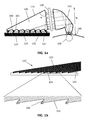
- the collimator 110 is designed such that, when a radiation beam is provided at the entrance of the collimator 110, the actual beam path is folded, as shown by way of example in FIG. 1a .
- the radiation beam may be folded over an angle between 30° and 150°, e.g. over an angle between 60° and 120°.
- the radiation at the entrance 150 may correspond with a diffuse source generating not collimated light, stemming from an irradiated tissue or interstitial fluid, e.g. at the skin.
- the angular spread of the radiation ranges between 0° and 90°, so that the radiation coming out of the diffuse scattering source, e.g. the skin, may be shaped as a full 90 degrees half cone.
- the radiation at entrance in the illustrative example has a photon flux of 10 7 -10 8 photons/sec.
- the radiation (e.g. Raman light leaving the skin) goes through a collimator 110 in which the area of the radiation is expanded and the radiation gets collimated.
- the exit area of the collimator of the exemplary system schematically presented in FIG.1a is 30 mm 2 and the angular spread of the outgoing radiation is 10.5°.
- the radiation leaving the collimator has an étendue of 1.2 mm 2 .
- the photon flux at the output of the collimator 110 equals 0.8 x 10 8 photons/sec in the example.
- the incoming light is oriented and collimated by reflection on the side walls of the collimator. The reflection may be based on total internal reflection or by a metallic coated surface with a high reflectance.
- the shape typically is optimized for redirecting the radiation and collimating it.
- the collimation part may be designed such that it resembles or is equal to a compound hyperbolic concentrator or a compound parabolic concentrator. Nevertheless, also other collimator elements based on lenses could be used.
- the collimator is limited in height.
- the height h c of the collimator in the example of FIG. 1a is about 5 mm
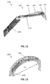
- the beam shaper 120 advantageously may have the shape of a wedge.
- the wedge 120 has a wedge entrance area 122 oriented towards the exit area of the collimator 110 and a wedge exit area 124 oriented towards the spectrometer chip 130.
- the cross-section of a wedge 120 is shown. The drawing is not at scale.
- the angle between the wedge entrance area 122 and the upper area of the wedge 123 is 90° so that irradiation entering the wedge perpendicularly to the wedge entrance does not hit the upper edge first but hits the wedge exit area 124 first.
- the angle ⁇ which is 90° in the exemplary embodiment of the present invention is not preserved in the drawing of the same exemplary invention.
- the enlarged portion in FIG. 1b illustrates how the reflection of the radiation occurs.
- the wedge exit area 124 has a waved or stepped pattern.
- a stepped pattern can be seen for the wedge exit area 124.
- the stepped exit area 124 thereby comprises first segments 310 which in some embodiments may be surfaces oriented orthogonally to the wedge entrance area 122. The distance between neighboring first segments 310 may be smaller than the length of the first segments 310.
- the stepped shape moreover comprises second segments 320 interconnecting the first segments 310.
- the second segments 320 may be flat surfaces or curved surfaces.
- the second segments 320 may be cylindrically shaped surfaces.
- the etendue is limited by the smallest etendue of the system, and while the etendue of the totality of the emitted light will increase, the etendue of the light reaching the grating couplers will have decreased, due to the limitations of the optics.
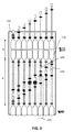
- the spectrometer chip comprises 200 lines wherein radiation is received.
- the height of the active part of the spectrometer chip equals 20 mm. This corresponds with a distance d l between the lines of 0.1 mm.
- Each line in the spectrometer chip comprising around 2000 x 2 waveguides.
- the spectrometer étendue is up to 0.58 mm 2 per photonics layer. With denser arrangements of waveguides, larger étendues per phtotonics layer may be possible. Multiple photonics layers can also be stacked to achieve higher overall étendues.
- the spectrally dependent transmission system 140 is a Fabry-Perot system.
- Other compact structures with spectrally tunable transmission can be used as spectrally dependent transmission system 140.
- the signal level is increased when the number of photons at the output of the spectrometer chip 130 is increased.
- the photon output of the spectrometer chip 130 is proportional to the étendue multiplied with the average photon transmission probability.
- the étendue per waveguide/incoupling grating 220 is limited. It is an advantage of embodiments of the present invention that a high photon output can be realized using a Fabry-Perot type spectrally dependent transmission system 140.
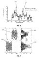
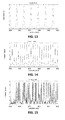
- FIG. 13, FIG. 14, and FIG. 15 show the transmission (T j ( ⁇ )) of a waveguide in an optical system according to an embodiment of the present invention.
- a Fabry-Perot type spectrally dependent transmission system 140 is assumed.
- the length of the waveguide is 0.03 mm in case of FIG. 13 , 0.1 mm in case of FIG. 14 and 0.5 mm in case of FIG. 15 .
- the figures show the transmission in function of the wavelength.
- the transmission is measured at the outcoupling grating 230.
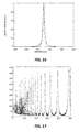
- FIG. 16 shows the incoming spectrum.
- the spectral intensity S( ⁇ ) is shown in function of the wavelength.
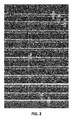
- FIG. 17 shows the transform of the spectrum response as a function of the waveguide index when the same spectrum is inserted in every waveguide.
- the input spectrum may be reconstructed based on the measurement results.
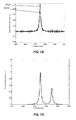
- the spectrum may be reconstructed using a least square fit. Such a reconstruction is shown in FIG. 18.
- FIG. 18 shows the input spectrum 1910 and shows the reconstructed spectrum 1920.
- the spectrum is reconstructed based on the measurement result shown in FIG. 17 .
- a complete reconstruction of the input spectrum is not required (e.g. for the estimation of a glucose concentration).
- FIG. 19 shows an input spectrum with a double peak. One at 885 nm and one at 875 nm.
- FIG. 20 shows the input spectrum 2110 as well as the reconstructed spectrum 2120.
- the overall optical density thus obtained may be above 9.
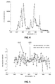
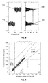
- FIG. 5 shows the measured spectrum 610 after an integration time of 10 seconds and the spectrum without noise 620.
- FIG. 6 shows the measured spectrum 710 after an integration time of 120 seconds and the spectrum without noise 720. Given a glucose spectrum P glucose x ⁇ det a SNR peak, sk i n of 1.7 can be obtained after a 10 seconds integration time and a SNR peak , skin of 6 can be obtained after a 120 seconds integration time.
- the estimated glucose concentration for a set of measurements on a sample without glucose is shown (910) as well as on a sample with 40 mg/dl of glucose (920).
- the histograms 930 and 940 are also shown. 500 fits were done without glucose (noise is seen as glucose contribution), and 500 fits with glucose at 40 mg/dl. 40 mg/dl is the minimum physiological concentration of glucose.
- FIG. 9 and FIG.10 show a Clarke error grid for the SNR system after a ten seconds integration time and 120 seconds integration time respectively.
- the incoupling efficiency ⁇ ic of both is equal to 2%
- the detector efficiency ⁇ det is equal to 30%.
- a background signal 1000 times stronger than the glucose signal is assumed.
- the SNR system corresponding with FIG. 9 is equal to 3.9 and the SNR system corresponding with FIG. 10 is equal to 13. From the graphs it can be concluded that a SNR system > 4 at the lowest physiological concentration of (40 mg/ dl) is sufficient for glucose concentration. It is an advantage of embodiments of the present invention that this signal to noise ratio can be obtained.
- the present invention relates to a detector system 1200.
- the detector system 1200 comprises an optical system 100 as indicated above being part of or being mounted on an optical printed circuit board 1210, including the optical part of the spectrometer.
- the detector system 1200 moreover comprises a read-out printed circuit board 1220 for reading out the optical signal received from the optical part of the spectrometer described in the first aspect.
- the read-out printed circuit board 1220 is connected with the optical printed circuit board 1210.
- the read-out printed circuit board 1220 digitizes the optical signal coming from the optical system 100 and/or processes the digitized result. An exemplary embodiment thereof is shown in FIG. 11 .
- the present invention also relates to an optical radiation guiding system comprising a collimator and beam shaper as described in the first aspect, without the optical part of the spectrometer being present.
- an optical radiation guiding system thus may be a separate components.
- Features and advantages thereof may be as described in the first aspect.
- RAMAN spectrometer in the embodiments of the present invention corresponds with an optical system according to the previous aspects of the present invention.
- an integrated circuit for performing spectroscopy on tissue comprises: a first optical unit comprising: a RAMAN spectrometer; an OCT spectrometer; an interferometer optically coupled to the OCT spectrometer; and a light coupler, positioned to couple scattered and reflected light from illuminated tissue into the RAMAN and OCT spectrometer; and an imaging region optically coupled to the RAMAN and OCT spectrometer.
- the integrated circuit further comprises at least a second optical unit, wherein the imaging region is optically coupled to the RAMAN and OCT spectrometer of each optical unit.
- the first optical unit further comprises an IR spectrometer optically coupled to the light coupler; and further comprising an infrared imaging region optically coupled to the IR spectrometer.
- an integrated circuit for performing spectroscopy on tissue comprises: a first optical unit comprising: a RAMAN spectrometer; an IR spectrometer; a light coupler, positioned to couple scattered and reflected light from illuminated tissue into the RAMAN and IR spectrometer; an imaging region optically coupled to the RAMAN spectrometer; and an infrared imaging region optically coupled to the IR spectrometer.
- the integrated circuit further comprises at least a second optical unit; wherein the imaging region is optically coupled to the RAMAN spectrometer of each optical unit; and wherein the infrared imaging region is optically coupled to the IR spectrometer of each optical unit.
- the first optical unit further comprises: an OCT spectrometer optically coupled to light coupler; and an interferometer optically coupled to the OCT spectrometer; and wherein the imaging region is optically coupled to the OCT spectrometer.
- the integrated circuit further comprises at least a second optical unit; wherein the imaging region is optically coupled to the RAMAN and OCT spectrometer of each optical unit; and wherein the infrared imaging region is optically coupled to the IR spectrometer of each optical unit.
- the integrated circuit further comprises at least one optical waveguide distributor for distributing a light beam of a light source on the integrated circuit thereby allowing simultaneous illumination of different locations of tissue.
- the integrated circuit further comprises at least one through-hole thereby allowing illumination of tissue through the integrated circuit.
- the integrated circuit further comprises at least one rejection filter located to allow, when in operation, only scattered light reaching the RAMAN spectrometer.
- the integrated circuit comprises a plurality of active electronic component layers thereby forming a three-dimensional integrated circuit wherein each active electronic component layer comprises the first optical unit or the at least one second optical unit.
- the integrated circuit may be a 3D (stacked) integrated circuit comprising different layers, each layer comprising an optical unit.
- the light coupler of the first or the at least one second optical unit of each active electronic component layer is configured to couple light with a different wavelength into the RAMAN spectrometer.
- Each light coupler of an optical unit present in a layer of the 3D integrated circuit may be configured to couple light with a specific wavelength in a spectrometer.
- the wavelength ranges of different light couplers may be adjacent to allow in coupling of light with wavelengths falling within a specific wavelength range.
- one or more photodiodes of the imaging region comprise a spectral filter for spectrally resolving RAMAN scattered light.
- At least one photodiode in the imaging region which may be present in an active electronic component layer of the integrated circuit, may comprise a spectral filter. Different photodiodes of the imaging region may comprise different spectral filters.
- a wearable system for non-invasive measuring of the concentration of an analyte in tissue comprising: an integrated circuit according to an embodiment of the disclosure; a first light source optically coupled to the integrated circuit and configured to emit a laser beam for performing Raman spectroscopy; a second light source optically coupled to the integrated circuit and configured to emit a broadband light beam for performing OCT spectroscopy or IR spectroscopy; read-out electronics electrically coupled to the integrated circuit and configured to read out and correlate spectroscopic data from the RAMAN and IR spectrometer or from the RAMAN and OCT spectrometer and to determine the concentration of an analyte using the correlated spectroscopic data.
- the system further comprises a third light source optically coupled to the integrated circuit and configured to emit a broadband light beam for performing IR spectroscopy or OCT spectroscopy; and wherein the read-out electronics is further configured to read out and correlate spectroscopic data from the RAMAN, OCT and IR spectrometer and determine the concentration of an analyte using the correlated spectroscopic data.
- the second light source is a low coherent light source or a very wide bandwidth source and the third light source is low coherent light source or a very wide bandwidth source.
- the system further comprises at least one optical reflector adapted to couple light from a light source in the integrated circuit.
- the tissue is skin tissue and the system is completely packaged in a wearable casing and the wearable casing is adapted to press the integrated circuit against the skin tissue of an individual when worn thereby allowing scattered and reflected light from illuminated skin tissue to be received by the integrated circuit.
- the wearable casing is a wristband, the size of the wristband being adaptable to allow pressing of the integrated circuit against the skin of an individual when worn.
- the wearable casing is a watch comprising a watch strap, the size of the watch strap being adaptable to allow pressing of the integrated circuit against the skin of an individual when worn.
- a method for non-invasive measuring of the concentration of analyte in tissue using the wearable system comprises: simultaneously obtaining spectra of Raman scattered light at different locations of the tissue; obtaining an optical model of the tissue; correlating the obtained spectra of Raman scattered light with the obtained optical model; determining the concentration of the analyte using the correlated data.
- obtaining an optical model of the tissue comprises determining thicknesses and optical properties of different layers of the tissue.
- the tissue is skin tissue and obtaining an optical model of the tissue comprises obtaining a skin model of skin tissue underneath the sensor, the skin model comprising information on thickness and optical properties of different layers of the skin tissue.
- the skin model further comprises information on the refractive index of interstitial fluid and blood in the skin tissue.
- the analyte is glucose.
- obtaining an optical model of the tissue is done using IR spectroscopy and/or using OCT spectroscopy.
- simultaneously obtaining spectra of Raman scattered light of the tissue at different locations and obtaining an optical model of the tissue is performed simultaneously.
Landscapes
- Physics & Mathematics (AREA)
- Spectroscopy & Molecular Physics (AREA)
- Health & Medical Sciences (AREA)
- General Physics & Mathematics (AREA)
- Life Sciences & Earth Sciences (AREA)
- Engineering & Computer Science (AREA)
- Biomedical Technology (AREA)
- General Health & Medical Sciences (AREA)
- Pathology (AREA)
- Optics & Photonics (AREA)
- Biophysics (AREA)
- Molecular Biology (AREA)
- Heart & Thoracic Surgery (AREA)
- Medical Informatics (AREA)
- Surgery (AREA)
- Animal Behavior & Ethology (AREA)
- Public Health (AREA)
- Veterinary Medicine (AREA)
- Chemical & Material Sciences (AREA)
- Hematology (AREA)
- Immunology (AREA)
- Biochemistry (AREA)
- Analytical Chemistry (AREA)
- Nuclear Medicine, Radiotherapy & Molecular Imaging (AREA)
- Emergency Medicine (AREA)
- Ecology (AREA)
- Dermatology (AREA)
- Urology & Nephrology (AREA)
- Food Science & Technology (AREA)
- Medicinal Chemistry (AREA)
- Radiology & Medical Imaging (AREA)
- Human Computer Interaction (AREA)
- Measurement Of The Respiration, Hearing Ability, Form, And Blood Characteristics Of Living Organisms (AREA)
- Investigating, Analyzing Materials By Fluorescence Or Luminescence (AREA)
Priority Applications (5)
| Application Number | Priority Date | Filing Date | Title |
|---|---|---|---|
| EP14157397.2A EP2913663A1 (fr) | 2014-02-28 | 2014-02-28 | Spectromètre optique à portée adaptée |
| US15/119,055 US9909992B2 (en) | 2014-02-28 | 2015-02-28 | Optical spectrometer with matched étendue |
| JP2016545927A JP6247770B2 (ja) | 2014-02-28 | 2015-02-28 | 適合したエテンデュを有する分光計 |
| PCT/EP2015/054225 WO2015128503A1 (fr) | 2014-02-28 | 2015-02-28 | Spectromètre optique avec étendue adaptée |
| EP15707139.0A EP3111197B1 (fr) | 2014-02-28 | 2015-02-28 | Spectromètre optique avec étendue adaptée |
Applications Claiming Priority (1)
| Application Number | Priority Date | Filing Date | Title |
|---|---|---|---|
| EP14157397.2A EP2913663A1 (fr) | 2014-02-28 | 2014-02-28 | Spectromètre optique à portée adaptée |
Publications (1)
| Publication Number | Publication Date |
|---|---|
| EP2913663A1 true EP2913663A1 (fr) | 2015-09-02 |
Family
ID=52596500
Family Applications (2)
| Application Number | Title | Priority Date | Filing Date |
|---|---|---|---|
| EP14157397.2A Withdrawn EP2913663A1 (fr) | 2014-02-28 | 2014-02-28 | Spectromètre optique à portée adaptée |
| EP15707139.0A Active EP3111197B1 (fr) | 2014-02-28 | 2015-02-28 | Spectromètre optique avec étendue adaptée |
Family Applications After (1)
| Application Number | Title | Priority Date | Filing Date |
|---|---|---|---|
| EP15707139.0A Active EP3111197B1 (fr) | 2014-02-28 | 2015-02-28 | Spectromètre optique avec étendue adaptée |
Country Status (4)
| Country | Link |
|---|---|
| US (1) | US9909992B2 (fr) |
| EP (2) | EP2913663A1 (fr) |
| JP (1) | JP6247770B2 (fr) |
| WO (1) | WO2015128503A1 (fr) |
Cited By (6)
| Publication number | Priority date | Publication date | Assignee | Title |
|---|---|---|---|---|
| WO2018217171A1 (fr) * | 2017-05-25 | 2018-11-29 | National University Of Singapore | Appareil, sonde optique et procédé de caractérisation in vivo d'un tissu |
| US10514333B2 (en) | 2015-06-30 | 2019-12-24 | Imec Vzw | Absorption spectrum detection of a fluid |
| US10578490B2 (en) | 2017-02-02 | 2020-03-03 | Samsung Electronics Co., Ltd. | Spectrometer and apparatus for measuring biological component using the same |
| US10656087B2 (en) | 2015-06-30 | 2020-05-19 | Imec Vzw | Detection of fluid absorption spectrum |
| EP3936842A1 (fr) | 2020-07-06 | 2022-01-12 | Imec VZW | Système de transmission de lumière pour fournir de la lumière à un spectromètre raman |
| US11280675B2 (en) | 2019-06-18 | 2022-03-22 | Ruolin Li | Method, system and apparatus for a Raman spectroscopic measurement system |
Families Citing this family (14)
| Publication number | Priority date | Publication date | Assignee | Title |
|---|---|---|---|---|
| US10254164B2 (en) | 2015-04-16 | 2019-04-09 | Nanommics, Inc. | Compact mapping spectrometer |
| US9924894B2 (en) * | 2015-06-03 | 2018-03-27 | Hong Kong Applied Science And Technology Research Institute Co. Ltd. | Non-invasive measurement of skin thickness and glucose concentration with Raman spectroscopy and method of calibration thereof |
| US10533993B2 (en) * | 2016-09-05 | 2020-01-14 | Cheng-Hao KO | Test strip, inspection system and inspection method thereof |
| EP3330759B1 (fr) | 2016-12-05 | 2025-02-12 | IMEC vzw | Coupleur de lumière à circuit photonique et procédé associé |
| CN109425572B (zh) * | 2017-08-30 | 2023-07-25 | 三星电子株式会社 | 用于光谱仪的收集光学系统和拉曼光谱系统 |
| EP3454023B1 (fr) * | 2017-08-30 | 2024-05-29 | Samsung Electronics Co., Ltd. | Système optique de collecte pour spectromètre et système spectral raman |
| KR101870837B1 (ko) * | 2017-11-17 | 2018-06-27 | 부경대학교 산학협력단 | 부갑상선 실시간 이미징 시스템 |
| US20200370958A1 (en) * | 2017-12-13 | 2020-11-26 | Trinamix Gmbh | Spectrometer device and system |
| KR20200095547A (ko) * | 2017-12-13 | 2020-08-10 | 트리나미엑스 게엠베하 | 분광계 장치 및 시스템 |
| US11627895B2 (en) * | 2018-08-10 | 2023-04-18 | Samsung Electronics Co., Ltd. | Apparatus and method for estimating analyte concentration, and apparatus and method for generating analyte concentration estimation model |
| WO2022032218A1 (fr) * | 2020-08-07 | 2022-02-10 | Endectra, Llc | Spectromètre portatif pour l'interrogation de biomolécules dans un tissu biologique |
| CN115078266B (zh) * | 2021-03-11 | 2025-07-04 | 上海与光彩芯科技有限公司 | 光学系统及其设计方法 |
| KR102535460B1 (ko) * | 2022-12-29 | 2023-05-30 | 주식회사 앤서레이 | 라만 분광 장비 |
| WO2025154634A1 (fr) * | 2024-01-19 | 2025-07-24 | 富士フイルム株式会社 | Capteur optique |
Citations (5)
| Publication number | Priority date | Publication date | Assignee | Title |
|---|---|---|---|---|
| US5011284A (en) * | 1990-03-22 | 1991-04-30 | Kaiser Optical Systems | Detection system for Raman scattering employing holographic diffraction |
| WO1997002475A1 (fr) * | 1995-07-05 | 1997-01-23 | Lockheed Martin Energy Systems, Inc. | Spectrometre monolithique et son procede de fabrication |
| US20070127019A1 (en) * | 2005-12-07 | 2007-06-07 | Anis Zribi | Collection probe for use in a Raman spectrometer system and methods of making and using the same |
| US7925069B2 (en) * | 1999-01-25 | 2011-04-12 | Amnis Corporation | Blood and cell analysis using an imaging flow cytometer |
| US20120275189A1 (en) * | 2011-04-26 | 2012-11-01 | Laine Jeffrey A | Patterned Light Distribution Device |
Family Cites Families (5)
| Publication number | Priority date | Publication date | Assignee | Title |
|---|---|---|---|---|
| EP1882916A1 (fr) * | 2006-07-20 | 2008-01-30 | Interuniversitair Microelektronica Centrum | Spectromètre catadioptrique compact |
| US8242462B2 (en) * | 2009-01-23 | 2012-08-14 | Lumencor, Inc. | Lighting design of high quality biomedical devices |
| GB0915775D0 (en) | 2009-09-09 | 2009-10-07 | Univ Gent | Implantable sensor |
| GB2489717B (en) * | 2011-04-05 | 2017-10-18 | Electronic Medical Solutions Ltd | Device and method for the detection of blood analytes |
| WO2013163298A1 (fr) * | 2012-04-24 | 2013-10-31 | Senseonics, Incorporated | Filtre passe-bande sélectif en angle d'incidence pour capteur chimique pouvant être implanté |
-
2014
- 2014-02-28 EP EP14157397.2A patent/EP2913663A1/fr not_active Withdrawn
-
2015
- 2015-02-28 JP JP2016545927A patent/JP6247770B2/ja not_active Expired - Fee Related
- 2015-02-28 US US15/119,055 patent/US9909992B2/en active Active
- 2015-02-28 EP EP15707139.0A patent/EP3111197B1/fr active Active
- 2015-02-28 WO PCT/EP2015/054225 patent/WO2015128503A1/fr not_active Ceased
Patent Citations (5)
| Publication number | Priority date | Publication date | Assignee | Title |
|---|---|---|---|---|
| US5011284A (en) * | 1990-03-22 | 1991-04-30 | Kaiser Optical Systems | Detection system for Raman scattering employing holographic diffraction |
| WO1997002475A1 (fr) * | 1995-07-05 | 1997-01-23 | Lockheed Martin Energy Systems, Inc. | Spectrometre monolithique et son procede de fabrication |
| US7925069B2 (en) * | 1999-01-25 | 2011-04-12 | Amnis Corporation | Blood and cell analysis using an imaging flow cytometer |
| US20070127019A1 (en) * | 2005-12-07 | 2007-06-07 | Anis Zribi | Collection probe for use in a Raman spectrometer system and methods of making and using the same |
| US20120275189A1 (en) * | 2011-04-26 | 2012-11-01 | Laine Jeffrey A | Patterned Light Distribution Device |
Cited By (6)
| Publication number | Priority date | Publication date | Assignee | Title |
|---|---|---|---|---|
| US10514333B2 (en) | 2015-06-30 | 2019-12-24 | Imec Vzw | Absorption spectrum detection of a fluid |
| US10656087B2 (en) | 2015-06-30 | 2020-05-19 | Imec Vzw | Detection of fluid absorption spectrum |
| US10578490B2 (en) | 2017-02-02 | 2020-03-03 | Samsung Electronics Co., Ltd. | Spectrometer and apparatus for measuring biological component using the same |
| WO2018217171A1 (fr) * | 2017-05-25 | 2018-11-29 | National University Of Singapore | Appareil, sonde optique et procédé de caractérisation in vivo d'un tissu |
| US11280675B2 (en) | 2019-06-18 | 2022-03-22 | Ruolin Li | Method, system and apparatus for a Raman spectroscopic measurement system |
| EP3936842A1 (fr) | 2020-07-06 | 2022-01-12 | Imec VZW | Système de transmission de lumière pour fournir de la lumière à un spectromètre raman |
Also Published As
| Publication number | Publication date |
|---|---|
| EP3111197B1 (fr) | 2018-02-28 |
| JP2017506738A (ja) | 2017-03-09 |
| EP3111197A1 (fr) | 2017-01-04 |
| US9909992B2 (en) | 2018-03-06 |
| JP6247770B2 (ja) | 2017-12-13 |
| WO2015128503A1 (fr) | 2015-09-03 |
| US20160356720A1 (en) | 2016-12-08 |
Similar Documents
| Publication | Publication Date | Title |
|---|---|---|
| EP3111197B1 (fr) | Spectromètre optique avec étendue adaptée | |
| EP3076871B1 (fr) | Dispositif et procédé pour des mesures non invasives d'analytes | |
| US6167290A (en) | Method and apparatus of non-invasive measurement of human/animal blood glucose and other metabolites | |
| Zhao et al. | Integrated real‐time Raman system for clinical in vivo skin analysis | |
| US7944555B2 (en) | High-speed, rugged, time-resolved, Raman spectrometer for sensing multiple components of a sample and for diagnostics of pathological skin conditions such as cancer | |
| US5842995A (en) | Spectroscopic probe for in vivo measurement of raman signals | |
| EP2130029B1 (fr) | Eclairage d'un milieu à diffusion diffuse | |
| US10520438B2 (en) | Collection optics system for spectrometer and Raman spectral system | |
| US20060106317A1 (en) | Optical system and use thereof for detecting patterns in biological tissue | |
| EP1931969A1 (fr) | Procédé et système de mesure de composition sous-jacente d un échantillon | |
| JP2023550206A (ja) | 被分析物の存在または濃度の非侵襲的インビボ(生体内)測定のためのラマンプローブおよび装置および方法 | |
| JP7253885B2 (ja) | 分光器用集光光学系、及びそれを含むラマン分光システム | |
| US10478106B2 (en) | Probe, system, and method for non-invasive measurement of blood analytes | |
| EP2896347A1 (fr) | Dispositif de mesure de lumière diffusée | |
| JP3992064B2 (ja) | 光学分析装置 | |
| JP4120684B2 (ja) | 分光分析法による血液成分濃度の分析装置 | |
| EP3454023B1 (fr) | Système optique de collecte pour spectromètre et système spectral raman | |
| Okubo et al. | Compact fluorescence endoscope with speckle-generating fiber probe | |
| JP2001041883A (ja) | 体液成分濃度の分析装置 |
Legal Events
| Date | Code | Title | Description |
|---|---|---|---|
| PUAI | Public reference made under article 153(3) epc to a published international application that has entered the european phase |
Free format text: ORIGINAL CODE: 0009012 |
|
| AK | Designated contracting states |
Kind code of ref document: A1 Designated state(s): AL AT BE BG CH CY CZ DE DK EE ES FI FR GB GR HR HU IE IS IT LI LT LU LV MC MK MT NL NO PL PT RO RS SE SI SK SM TR |
|
| AX | Request for extension of the european patent |
Extension state: BA ME |
|
| STAA | Information on the status of an ep patent application or granted ep patent |
Free format text: STATUS: THE APPLICATION IS DEEMED TO BE WITHDRAWN |
|
| 18D | Application deemed to be withdrawn |
Effective date: 20160303 |