EP2913697A1 - Optiksystem und damit ausgestattete optische vorrichtung - Google Patents
Optiksystem und damit ausgestattete optische vorrichtung Download PDFInfo
- Publication number
- EP2913697A1 EP2913697A1 EP13849089.1A EP13849089A EP2913697A1 EP 2913697 A1 EP2913697 A1 EP 2913697A1 EP 13849089 A EP13849089 A EP 13849089A EP 2913697 A1 EP2913697 A1 EP 2913697A1
- Authority
- EP
- European Patent Office
- Prior art keywords
- lens group
- lens
- optical system
- stop member
- end state
- Prior art date
- Legal status (The legal status is an assumption and is not a legal conclusion. Google has not performed a legal analysis and makes no representation as to the accuracy of the status listed.)
- Withdrawn
Links
Images




Classifications
-
- G—PHYSICS
- G02—OPTICS
- G02B—OPTICAL ELEMENTS, SYSTEMS OR APPARATUS
- G02B15/00—Optical objectives with means for varying the magnification
- G02B15/14—Optical objectives with means for varying the magnification by axial movement of one or more lenses or groups of lenses relative to the image plane for continuously varying the equivalent focal length of the objective
- G02B15/144—Optical objectives with means for varying the magnification by axial movement of one or more lenses or groups of lenses relative to the image plane for continuously varying the equivalent focal length of the objective having four groups only
- G02B15/1441—Optical objectives with means for varying the magnification by axial movement of one or more lenses or groups of lenses relative to the image plane for continuously varying the equivalent focal length of the objective having four groups only the first group being positive
- G02B15/144113—Optical objectives with means for varying the magnification by axial movement of one or more lenses or groups of lenses relative to the image plane for continuously varying the equivalent focal length of the objective having four groups only the first group being positive arranged +-++
-
- G—PHYSICS
- G02—OPTICS
- G02B—OPTICAL ELEMENTS, SYSTEMS OR APPARATUS
- G02B13/00—Optical objectives specially designed for the purposes specified below
- G02B13/18—Optical objectives specially designed for the purposes specified below with lenses having one or more non-spherical faces, e.g. for reducing geometrical aberration
-
- G—PHYSICS
- G02—OPTICS
- G02B—OPTICAL ELEMENTS, SYSTEMS OR APPARATUS
- G02B15/00—Optical objectives with means for varying the magnification
- G02B15/14—Optical objectives with means for varying the magnification by axial movement of one or more lenses or groups of lenses relative to the image plane for continuously varying the equivalent focal length of the objective
- G02B15/142—Optical objectives with means for varying the magnification by axial movement of one or more lenses or groups of lenses relative to the image plane for continuously varying the equivalent focal length of the objective having two groups only
-
- G—PHYSICS
- G02—OPTICS
- G02B—OPTICAL ELEMENTS, SYSTEMS OR APPARATUS
- G02B15/00—Optical objectives with means for varying the magnification
- G02B15/14—Optical objectives with means for varying the magnification by axial movement of one or more lenses or groups of lenses relative to the image plane for continuously varying the equivalent focal length of the objective
- G02B15/145—Optical objectives with means for varying the magnification by axial movement of one or more lenses or groups of lenses relative to the image plane for continuously varying the equivalent focal length of the objective having five groups only
- G02B15/1451—Optical objectives with means for varying the magnification by axial movement of one or more lenses or groups of lenses relative to the image plane for continuously varying the equivalent focal length of the objective having five groups only the first group being positive
- G02B15/145121—Optical objectives with means for varying the magnification by axial movement of one or more lenses or groups of lenses relative to the image plane for continuously varying the equivalent focal length of the objective having five groups only the first group being positive arranged +-+-+
-
- G—PHYSICS
- G02—OPTICS
- G02B—OPTICAL ELEMENTS, SYSTEMS OR APPARATUS
- G02B15/00—Optical objectives with means for varying the magnification
- G02B15/14—Optical objectives with means for varying the magnification by axial movement of one or more lenses or groups of lenses relative to the image plane for continuously varying the equivalent focal length of the objective
- G02B15/16—Optical objectives with means for varying the magnification by axial movement of one or more lenses or groups of lenses relative to the image plane for continuously varying the equivalent focal length of the objective with interdependent non-linearly related movements between one lens or lens group, and another lens or lens group
- G02B15/20—Optical objectives with means for varying the magnification by axial movement of one or more lenses or groups of lenses relative to the image plane for continuously varying the equivalent focal length of the objective with interdependent non-linearly related movements between one lens or lens group, and another lens or lens group having an additional movable lens or lens group for varying the objective focal length
-
- G—PHYSICS
- G02—OPTICS
- G02B—OPTICAL ELEMENTS, SYSTEMS OR APPARATUS
- G02B9/00—Optical objectives characterised both by the number of the components and their arrangements according to their sign, i.e. + or -
- G02B9/04—Optical objectives characterised both by the number of the components and their arrangements according to their sign, i.e. + or - having two components only
-
- G—PHYSICS
- G02—OPTICS
- G02B—OPTICAL ELEMENTS, SYSTEMS OR APPARATUS
- G02B9/00—Optical objectives characterised both by the number of the components and their arrangements according to their sign, i.e. + or -
- G02B9/04—Optical objectives characterised both by the number of the components and their arrangements according to their sign, i.e. + or - having two components only
- G02B9/10—Optical objectives characterised both by the number of the components and their arrangements according to their sign, i.e. + or - having two components only one + and one - component
-
- G—PHYSICS
- G02—OPTICS
- G02B—OPTICAL ELEMENTS, SYSTEMS OR APPARATUS
- G02B1/00—Optical elements characterised by the material of which they are made; Optical coatings for optical elements
- G02B1/10—Optical coatings produced by application to, or surface treatment of, optical elements
- G02B1/11—Anti-reflection coatings
-
- G—PHYSICS
- G02—OPTICS
- G02B—OPTICAL ELEMENTS, SYSTEMS OR APPARATUS
- G02B27/00—Optical systems or apparatus not provided for by any of the groups G02B1/00 - G02B26/00, G02B30/00
- G02B27/64—Imaging systems using optical elements for stabilisation of the lateral and angular position of the image
- G02B27/646—Imaging systems using optical elements for stabilisation of the lateral and angular position of the image compensating for small deviations, e.g. due to vibration or shake
Definitions
- the present invention relates to an optical system and an optical apparatus equipped therewith.
- Patent Document 1 Japanese Patent Application Laid-open No. 2001-296465
- the present invention is made in view of the above-described problem, and has an object to provide an optical system and an optical apparatus equipped therewith, the optical system being capable of reducing light outside of an effective light flux (beyond the maximum angle of view) of the optical system that light is collected on the position of the focal point of the most object side lens group having positive refractive power, thereby reducing generation of heat by a member in the vicinity of the focal point of the lens group having positive refractive power so that it is possible to prevent the member from being deformed and deteriorated, thus reducing the influence on the imaging performance.
- the present invention provides an optical system which comprises a first lens group disposed at a most object side and having positive refractive power; a stop member disposed at an image side of the first lens group; and a second lens group disposed at an image side of the stop member; and the following conditional expressions being satisfied: 0.20 ⁇ ds / f ⁇ 1 ⁇ 0.60 1.00 ⁇ ⁇ ⁇ 2 ⁇ ⁇ s ⁇ 0.8 ⁇ ⁇ ⁇ 1 (unit: mm) where ds denotes a distance along the optical axis between a lens surface of a most image side lens in the first lens group and the aperture stop, f1 denotes a focal length of the first lens group, ⁇ 1 denotes an outer diameter of the most image side lens in the first lens group, ⁇ 2 denotes an outer diameter of a most object side lens in the second lens group, and ⁇ s denotes a diameter of an aperture of the stop member.
- the present invention provides an optical apparatus equipped with the optical system.
- an optical system and an optical apparatus equipped therewith the optical system being capable of reducing light outside of an effective light flux of the optical system (beyond the maximum angle of view), that light being collected on the position of the focal point of the most object side lens group having positive refractive power, thereby capable of reducing heat from being generated by a member in the vicinity of the focal point, so that it is possible to prevent the member from being deformed and deteriorated, thus reducing affecting on imaging performance.
- the optical system of the present application is characterized in comprising a first lens group disposed in a most object side and having positive refractive power, a stop member disposed at an image side of the first lens group and a second lens group disposed at an image side of the stop member.
- An optical system is characterized in having a state where the following conditional expressions (1) and (2) are satisfied: 0.20 ⁇ ds / f ⁇ 1 ⁇ 0.60 1.00 ⁇ ⁇ ⁇ 2 ⁇ ⁇ s ⁇ 0.8 ⁇ ⁇ ⁇ 1 (unit: mm) where ds denotes a distance along the optical axis between a lens surface of a most image side lens in the first lens group and the aperture stop, f1 denotes a focal length of the first lens group, ⁇ 1 denotes an outer diameter of the most image side lens in the first lens group, ⁇ 2 denotes an outer diameter of a most object side lens in the second lens group, and ⁇ s denotes a diameter of an aperture of the stop member.
- the conditional expression (1) defines a relation of an optimum position of the stop member on the optical axis to the focal length of the first lens group.
- the optical system of the present application can reduce light outside of the effective light flux (beyond the maximum angle of view) that is collected on the focal point position of the first lens group having positive refractive power, so that heat generation of a member in the vicinity of the focusing position is reduced, thereby deformation as well as deterioration of the member being reduced and thus the influence on the image performance is able to be reduced.
- conditional expression (1) When the value ds/f1 of conditional expression (1) is equal to or falls below the lower limit, it becomes not possible to reduce superbly light out of an effective light flux (beyond the maximum angle of view) that is collected on the focal point position of the first lens group having positive refractive power and it becomes difficult to reduce the influence on the imaging performance. This is not preferable.
- conditional expression (1) when the value ds/f1 of conditional expression (1) is equal to or exceeds the upper limit, an end of the stop member is located in the effective light flux and blocks the effective light flux from passing, and thereby the imaging performance being influenced, so it is not preferable. Further, light rays are collected on the end of the stop member, so that the stop member generates heat, thereby the imaging performance being influenced. This is not preferable.
- the conditional expression (2) defines a proper aperture diameter of the stop member with a relation of outer diameters of the first lens group and the second lens group.
- the aperture diameter of the stop member is larger than the effective diameter of the optical system in the position of the stop member along the optical axis.
- an aperture diameter of the stop member is larger than an effective diameter of the optical system in a position of the stop member along the optical axis.
- the aperture diameter of the stop member is not larger than the effective diameter, light rays are apt to impinge on the stop member, be reflected thereby and reach an imaging area as flare, so the imaging performance is deteriorated. It is not preferable.
- the optical system of the present application it is desirable that the optical system is able to vary magnification and upon varying magnification from a wide angle end state to a telephoto end state, a distance between the first lens group and the second lens group varies. With this configuration, the optical system of the present application can realize a variable magnification optical system having a superb imaging performance.
- the optical system of the present application it is desirable that the optical system is able to vary magnification and upon varying magnification from a wide angle end state to a telephoto end state, a distance between the first lens group and the stop member varies.
- the optical system of the present application can reduce light outside of the effective light flux (beyond the maximum angle of view) that is collected on the focal point position of a lens group having positive refractive power, without influencing on the effective light flux, so that in a state where a member in the vicinity of the focal point position generates easily heat, that is in a state where the first lens group and the second lens group are apart from each other, it becomes possible to make a state where heat generation is least, thereby deformation as well as deterioration of the member being reduced and thus it is possible to reduce the influence on the image performance.
- the optical system of the present application it is desirable that the optical system is able to vary magnification, and upon varying magnification from a wide angle end state to a telephoto end state, a distance between the second lens group and the stop member varies.
- the optical system of the present application can reduce light outside of the effective light flux (beyond the maximum angle of view) that is collected on the focal point position of a lens group having positive refractive power, without influencing on the effective light flux, so that in a state where a member in the vicinity of the focal point position generates easily heat, that is in a state where the first lens group and the second lens group are apart from each other, it becomes possible to make a state where heat generation is least, thereby deformation as well as deterioration of the member being reduced and thus it is possible to reduce the influence on the image performance.
- the optical system is able to vary magnification, and the optical system comprises a moving mechanism for moving the stop member along the optical axis upon varying magnification from a wide angle end state to a telephoto end state.
- the optical system of the present application allows the stop member to be disposed at an optimum position in the variable magnification optical system, so that the optical system can reduce light outside of the effective light flux (beyond the maximum angle of view) that is collected on the focal point position of a lens group having positive refractive power, and heat generation of a member in the vicinity of the focal point position is reduced, thereby deformation as well as deterioration of the member being reduced and thus it being possible to realize a variable magnification optical system in which the influence on the image performance is reduced.
- the stop member has an antireflection member on a surface thereof.
- the optical system of the present application can reduce flare light that is generated by light rays which are outside of the effective light flux (beyond the maximum field of view), impinge on the surface of the stop member and reflected thereby and repeatedly reflected by an internal surface of a lens barrel and reach the imaging plane, so that influence on the imaging performance is reduced.
- the optical system of the present application it is desirable that a position of an optical axis side end of the stop member in the direction of the optical axis is at a more image side than a position of a barrel side end of the stop member in the direction of the optical axis.
- the optical system of the present application can prevent various members disposed in the lens barrel and the ends of the stop member from interfering with each other, so that the stop member is disposed at a optimum position.
- the optical system of the present application can reduce light outside of the effective light flux (beyond the maximum angle of view) that is collected on the focal point position of the lens group having positive refractive power, without influencing on the effective light flux, so that heat generation of a member in the vicinity of the focal point position is reduced, thereby deformation as well as deterioration of the member being reduced and thus the influence on the image performance is reduced.
- the optical apparatus of the present application is characterized in comprising the optical system having the configuration as described above.
- variable magnification optical system that is an optical system according to each numerical Example of the present application is explained with reference to the accompanying drawings.
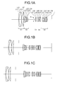
- Figs. 1A, 1B and 1C are sectional views showing an optical system according to a First Example of the present application, in a wide angle end state W, in an intermediate focal length state M and in a telephoto end state T, respectively.
- the optical system according to the First Example of the present application is composed of a first lens group G1 disposed at a most object side and having positive refractive power, a second lens group G2 disposed at an image side of the first lens group G1 and having negative refractive power, a third lens group G3 disposed at an image side of the second lens group G2 and having positive refractive power, a fourth lens group G4 disposed at an image side of the third lens group G3 and having negative refractive power and a fifth lens group G5 disposed at an image side of the fourth lens group G4 and having positive refractive power.
- An aperture stop S is disposed at the image side of the third lens group G3.
- the first lens group G1 is composed of, in order from the object, a cemented lens constructed by a negative meniscus lens L11 having a convex surface facing the object side cemented with a double convex positive lens L12, and a positive meniscus lens L13 having a convex surface facing the object side.
- the second lens group G2 is composed of, in order from the object side, a negative meniscus lens L21 having a convex surface facing the object side, a double concave negative lens L22, a double convex positive lens L23, and a negative meniscus lens L24 having a concave surface facing the object side.
- the negative meniscus lens L24 is a glass mold type aspherical lens whose object side lens surface is aspherically shaped.
- a stop member ST is disposed between the first lens group G1 and the second lens group G2.
- the third lens group G3 is composed of, in order from the object, a cemented lens constructed by a negative meniscus lens L31 having a convex surface facing the object side cemented with a double convex positive lens L32.
- the fourth lens group G4 is composed of, in order from the object, a cemented lens constructed by a double convex positive lens L41 cemented with a double concave negative lens L42 and a cemented lens constructed by a double concave negative lens L43 cemented with a positive meniscus lens L44 having a convex surface facing the object side.
- the double concave negative lens L42 is a glass mold type aspherical lens whose object side surface is aspherically shaped.
- the fifth lens group G5 is composed of, in order from the object side, a double convex positive lens L51, a cemented lens constructed by a double convex positive lens L52 cemented with a negative meniscus lens L53 having a concave surface facing the object side, a cemented lens constructed by a negative meniscus lens L54 having a convex surface facing the object side cemented with a double convex positive lens L55, and a negative meniscus lens L56 having a convex surface facing the object side.
- the negative meniscus lens L56 is a glass mold type aspherical lens whose image side lens surface is aspherically shaped, and light rays exitted from the negative meniscus lens L56 forms an image on an imaging plane I.
- the first lens group G1 is moved toward the object side monotonously
- the second lens group G2 is moved toward the object side from the wide angle end state W to the intermediate focal length state M and toward the image side from the intermediate focal length state M to the telephoto end state T
- the third lens group G3 is moved toward the object side monotonously
- the aperture stop S, the fourth lens group G4 and the fifth lens group G5 are moved toward the object side from the wide angle end state W to the intermediate focal length state M and toward the image side from the intermediate focal length state M to the telephoto end state T, such that a distance between the first lens group G1 and the second lens group G2 is increased, a distance between the second lens group G2 and the third lens group G3 is decreased, a distance between the third lens group G3 and the fourth lens group G4 is increased, a distance between the fourth lens group G4 and the fifth lens group G5
- a low pass filter, a glass for covering a sensor and the like which are not illustrated may be disposed between the negative meniscus lens L56 and the image plane I.
- Table 1 below shows various values of the variable magnification optical system according to the present Example.
- f denotes a focal length
- BF denotes a back focal length (a distance on the optical axis between the most image side lens surface and the image plane I).
- a surface number denotes an order of an optical surface counted from the object side
- r denotes a radius of curvature
- d denotes a surface-to-surface distance(an interval from an n-th surface to an (n+1)-th surface, where n is an integer.
- OP denotes an object surface
- variable denotes a variable surface-to-surface distance
- STOP denotes an aperture stop S.
- the position of an aspherical surface is expressed by attaching "*" to the surface number, and in the column of the radius of curvature, a paraxial radius of curvature is shown.
- E-n where n is an integer, denotes “ ⁇ 10 -n ", for example, "1.234E-05” denotes “1.234 ⁇ 10 -5 ".
- the 2nd order aspherical surface coefficient A2 is 0, and omitted in the description.
- FNO denotes an f-number
- ⁇ denotes a half angle of view(unit "°")
- Y denotes an image height
- TL denotes a total length of the variable magnification optical system, that is, a distance along the optical axis from the first surface to the image plane I upon focusing on an infinitely distant object
- dn denotes a variable interval between an n-th surface and an (n+1)-th surface
- ⁇ denotes an aperture diameter of the aperture stop S.
- W denotes a wide-angle end state
- M denotes an intermediate focal length state
- T denotes a telephoto end state.
- ST denotes a starting surface number and a focal length of each lens group.
- d1 denotes a distance measured along the optical axis from the most image side lens surface of the first lens group G1 to the most object side lens surface of the second lens group G2
- ds denotes a distance measured along the optical axis between the most image side lens surface of the first lens group G1 and the aperture portion of the stop member ST
- ds2 denotes a distance measured along the optical axis between the aperture portion of the stop member ST and the most object side lens surface of the second lens group G2
- ⁇ e denotes an effective diameter of light rays at the position of the stop member ST
- ⁇ s denotes an aperture diameter of the stop member ST
- ⁇ 1 denotes an outer diameter of the lens L13 disposed at the most image side of the first lens group G1
- ⁇ 2 denotes an outer diameter of the lens L12 disposed at the most object side of the second lens group G2.
- mm is generally used for the unit of length such as the focal length f, the radius of curvature r and the unit for other lengths shown in Table 1.
- the unit is not necessarily to be limited to "mm”.
- the aperture diameter ⁇ s of the stop member ST is larger than the effective diameter ⁇ e of the light rays at the position of the stop member ST.
- a light reduction ratio by the stop member ST in the telephoto end state T is about 25% in the imaging point position of the first lens group G1 at the height 22mm from the optical axis, thus attaining sufficient light reduction effect.
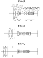
- Figs. 2A, 2B and 2C are sectional views of an optical system according to the Second Example of the present application, in a wide angle end state W, in an intermediate focal length state M and in a telephoto end state T, respectively.
- the optical system according to the Second Example of the present application is composed of a first lens group G1 disposed at a most object side and having positive refractive power, a second lens group G2 disposed at an image side of the first lens group G1 and having negative refractive power, a third lens group G3 disposed at an image side of the second lens group G2 and having positive refractive power, a fourth lens group G4 disposed at an image side of the third lens group G3 and having negative refractive power and a fifth lens group G5 disposed at an image side of the fourth lens group G4 and having positive refractive power.
- An aperture stop S is disposed at an object side of the third lens group G3.
- a stop member ST is disposed between the first lens group G1 and the second lens group G2.
- the first lens group G1 is composed of, in order from the object side, a cemented lens constructed by a negative meniscus lens L11 having a convex surface facing the object side cemented with a double convex positive lens L12, and a positive meniscus lens L13 having a convex surface facing the object side.
- the second lens group G2 is composed of, in order from the object side, a negative meniscus lens L21 having a convex surface facing the object side, a double concave negative lens L22, a double convex positive lens L23, and a negative meniscus lens L24 having a concave surface facing the object side.
- the negative meniscus lens L24 is a glass mold type aspherical lens whose object side lens surface is aspherically shaped.
- the third lens group G3 is composed of, in order from the object side, a cemented lens constructed by a negative meniscus lens L31 having a convex surface facing the object side cemented with a double convex positive lens L32.
- the fourth lens group G4 is composed of, in order from the object, a cemented lens constructed by a double convex positive lens L41 cemented with a double concave negative lens L42, and a cemented lens constructed by a double concave negative lens L43 cemented with a positive meniscus lens L44 having a convex surface facing the object side.
- the double concave negative lens L42 is a glass mold type aspherical lens whose object side surface is aspherically shaped.
- the fifth lens group G5 is composed of, in order from the object side, a double convex positive lens L51, a cemented lens constructed by a double convex positive lens L52 cemented with a negative meniscus lens L53 having a concave surface facing the object side, a cemented lens constructed by a negative meniscus lens L54 having a convex surface facing the object side cemented with a double convex positive lens L55, and a negative meniscus lens L56 having a convex surface facing the object side.
- the negative meniscus lens L56 is a glass mold type aspherical lens whose image side lens surface is aspherically shaped, and light rays exitted from the negative meniscus lens L56 form an image on an imaging plane I.
- variable magnification optical system upon zooming from the wide angle end state W to the telephoto end state T, with respect to the imaging plane I, the first lens group G1 is moved toward the object side monotonously, the second lens group G2 is moved toward the object side from the wide angle end state W to the intermediate focal length state M and toward the image side from the intermediate focal length state M to the telephoto end state T, the third lens group G3 is moved toward the object side monotonously, the aperture stop S, the fourth lens group G4 and the fifth lens group G5 are moved toward the object side from the wide angle end state W to the intermediate focal length state M and toward the image side from the intermediate focal length state M to the telephoto end state T, such that a distance between the first lens group G1 and the second lens group G2 is increased, a distance between the second lens group G2 and the third lens group G3 is decreased, a distance between the third lens group G3 and the fourth lens group G4 is increased, a distance between the fourth lens group G
- the stop member ST upon zooming from the wide angle end state W to the telephoto end state T, a distance between the first lens group G1 and the stop member ST is increased, and a distance between the stop member ST and the second lens group G2 is increased.
- a low pass filter, a glass for covering a sensor and the like which are not illustrated may be disposed between the negative meniscus lens L56 and the image plane I.
- Table 2 shows various values of the variable magnification optical system according to the present Second Example.
- Table 2 Second Example [Surface Data] Surface number r d nd ⁇ d OP ⁇ 1 104.5118 1.6000 2.003300 28.27 2 39.3751 7.4000 1.497820 82.57 3 -463.5701 0.1000 4 40.3116 5.4000 1.834810 42.73 5 241.9089 variable *6 79.9711 1.0000 1.851350 40.10 7 8.1252 4.8500 8 -14.2116 1.0000 1.883000 40.66 9 124.9279 0.1000 10 30.8124 3.3500 1.808090 22.74 11 -15.1873 0.3000 12 -13.2222 1.0000 1.883000 40.66 13 -23.0302 variable 14 (STOP) ⁇ variable 15 26.1923 1.0000 1.954000 33.46 16 12.2483 2.8500 1.719990 50.27 17 -43.5073 variable 18 14.5527 2.8500 1.497820 82.57 19
- the aperture diameter ⁇ s of the stop member ST is larger than the effective diameter ⁇ e of the light rays at the position of the stop member ST.
- a light reduction ratio by the stop member ST in the telephoto end state T is about 55% in the imaging point position of the first lens group G1 at the height 22mm from the optical axis, thus attaining sufficient light reduction effect.
- Figs. 3A, 3B and 3C are sectional views showing an optical system according to a Third Example of the present application, in a wide angle end state W, in an intermediate focal length state M and in a telephoto end state T, respectively.
- the optical system according to the third Example of the present application is composed of a first lens group G1 disposed at the most object side and having positive refractive power, a second lens group G2 disposed at an image side of the first lens group G1 and having negative refractive power, a third lens group G3 disposed at an image side of the second lens group G2 and having positive refractive power, a fourth lens group G4 disposed at an image side of the third lens group G3 and having positive refractive power.
- An aperture stop S is disposed at an object side of the third lens group G3.
- the first lens group G1 is composed of, in order from the object side, a cemented lens constructed by a negative meniscus lens L11 having a convex surface facing the object side cemented with a double convex positive lens L12, and a plano-convex positive lens L13 having a convex surface facing the object side.
- the second lens group G2 is composed of, in order from the object side, a negative meniscus lens L21 having a convex surface facing the object side, a negative meniscus lens L22 having a concave surface facing the object side, and a cemented lens constructed by a double convex positive lens L23 cemented with a negative meniscus lens L24 having a concave surface facing the object side.
- the negative meniscus lens L21 is a compound-type aspherical lens formed by a resin material and a glass material, whose object side lens surface is aspherically shaped.
- a stop member ST is disposed between the first lens group G1 and the second lens group G2.
- the third lens group G3 is composed of, in order from the object side, a cemented lens constructed by a negative meniscus lens L31 having a convex surface facing the object side cemented with a double convex positive lens L32.
- the fourth lens group G4 is composed of, in order from the object, a cemented lens constructed by a double convex positive lens L41 cemented with a negative meniscus lens L42 having a convex surface facing the image side, a cemented lens constructed by a positive meniscus lens L43 having a concave surface facing the object side cemented with a double concave negative lens L44, a double convex positive lens L45, a cemented lens constructed by a double convex positive lens L46 cemented with a double concave negative lens L47, a cemented lens constructed by a double convex positive lens L48 cemented with a negative meniscus lens L49 having a convex surface facing the image side, and a negative meniscus lens L410 having a concave surface facing the object side.
- the double concave negative lens L44 is a glass mold type aspherical lens whose image side surface is aspherically shaped
- the negative meniscus lens L410 is a glass mold type aspherical lens whose image side surface is aspherically shaped. Light rays exited from the negative meniscus lens L410 forms an image on an imaging plane I.
- the first lens group G1 is moved toward the object side monotonously
- the second lens group G2 is moved toward the object side
- the aperture stop S, the third lens group G3 and the fourth lens group G4 are moved toward the object side monotonously, such that a distance between the first lens group G1 and the second lens group G2 is increased, a distance between the second lens group G2 and the third lens group G3 is decreased, a distance between the third lens group G3 and the fourth lens group G4 is decreased from the wide angle end state W to the intermediate focal length state M and is increased from the intermediate focal length state M to the telephoto end state T, and a distance between the aperture stop S and the third lens group G3 is increased from the wide angle end state W to the intermediate focal length state M and is decreased from the intermediate focal length state M to the telephoto end state T.
- a low pass filter, a glass for covering a sensor and the like which are not illustrated may be disposed between the negative meniscus lens L19 and the image plane I.
- Table 3 shows various values of the lens system according to the Third Example.
- Table 3 Third Example [Surface Data] Surface number r d nd ⁇ d OP ⁇ 1 145.1831 1.7000 2.001000 29.14 2 36.6390 8.1000 1.497820 82.57 3 -399.3519 0.1000 4 43.2076 6.0000 1.883000 40.66 5 ⁇ variable *6 436.5967 0.1000 1.553890 38.09 7 87.0031 1.1000 1.834810 42.73 8 8.3001 5.3500 9 -12.6073 1.0000 1.755000 52.34 10 -32.7993 0.8000 11 41.1197 2.9500 1.808090 22.74 12 -19.6043 0.9000 1.883000 40.66 13 -73.1316 variable 14 (STOP) ⁇ variable 15 22.3725 0.9000 1.902650 35.73 16 12.2299 3.4500 1.670030 47.14 17 -59.6992 variable 18 13.7390 3.6000 1.497820 82.57 19
- the aperture diameter ⁇ s of the stop member ST is larger than the effective diameter ⁇ e of the light rays at the position of the stop member ST.
- a light reduction ratio by the stop member ST in the telephoto end state T is about 33% in the imaging point position of the first lens group G1 at the height 22mm from the optical axis, thus attaining sufficient light reduction effect.
- Figs. 4A, 4B and 4C are sectional views showing an optical system according to the Fourth Example of the present application, in a wide angle end state W, in an intermediate focal length state M and in a telephoto end state T, respectively.
- the optical system according to the Fourth Example of the present application is composed of a first lens group G1 disposed at a most object side and having positive refractive power, a second lens group G2 disposed at an image side of the first lens group G1 and having negative refractive power, a third lens group G3 disposed at an image side of the second lens group G2 and having positive refractive power, a fourth lens group G4 disposed at an image side of the third lens group G3 and having positive refractive power.
- An aperture stop S is disposed at an object side of the third lens group G3.
- the first lens group G1 is composed of, in order from the object side, a cemented lens constructed by a negative meniscus lens L11 having a convex surface facing the object side cemented with a double convex positive lens L12, and a plano-convex positive lens L13 having a convex surface facing the object side.
- the second lens group G2 is composed of, in order from the object side, a negative meniscus lens L21 having a convex surface facing the object side, a negative meniscus lens L22 having a concave surface facing the object side, and a cemented lens constructed by a double convex positive lens L23 cemented with a negative meniscus lens L24 having a concave surface facing the object side, and a negative meniscus lens L24 having a concave surface facing the object side.
- the negative meniscus lens L21 is a compound-type aspherical lens formed by a resin material and a glass material, whose object side lens surface is aspherically shaped.
- the stop member ST is disposed between the first lens group G1 and the second lens group G2.
- the third lens group G3 is composed of, in order from the object side, a cemented lens constructed by a negative meniscus lens L31 having a convex surface facing the object side cemented with a double convex positive lens L32.
- the fourth lens group G4 is composed of, in order from the object side, a cemented lens constructed by a double convex positive lens L41 cemented with a negative meniscus lens L42 having a convex surface facing the image side, a cemented lens constructed by a positive meniscus lens L43 having a concave surface facing the object side cemented with a double concave negative lens L44, a double convex positive lens L45, a cemented lens constructed by a double convex positive lens L46 cemented with a double concave negative lens L47, a cemented lens constructed by a double convex positive lens L48 cemented with a negative meniscus lens L49 having a convex surface facing the image side, and a negative meniscus lens L410 having a concave surface facing the object side.
- the double concave negative lens L44 is a glass mold type aspherical lens whose image side surface is aspherically shaped
- the negative meniscus lens L410 is a glass mold type aspherical lens whose image side surface is aspherically shaped. Light rays exited from the negative meniscus lens L410 forms an image on the image plane I.
- the first lens group G1 is moved toward the object side monotonously
- the second lens group G2 is moved toward the object side
- the aperture stop S, the third lens group G3 and the fourth lens group G4 are moved monotonously toward the object side, such that a distance between the first lens group G1 and the second lens group G2 is increased, a distance between the second lens group G2 and the third lens group G3 is decreased, a distance between the third lens group G3 and the fourth lens group G4 is decreased from the wide angle end state W to the intermediate focal length state M and increased from the intermediate focal length state M to the telephoto end state T, and a distance between the aperture stop S and the third lens group G3 is increased from the wide angle end state W to the intermediate focal length state M and decreased from the intermediate focal length state M to the telephoto end state T.
- the stop member ST upon zooming from the wide angle end state W to the telephoto end state T, a distance between the first lens group G1 and the stop member ST is increased, and a distance between the stop member ST and the second lens group G2 is increased.
- a low pass filter, a glass for covering a sensor and the like which are not illustrated, may be disposed between the negative meniscus lens L19 and the image plane I.
- Table 4 shows various values of the variable magnification optical system according to the present Fourth Example.
- Table 4 Fourth Example [Surface Data] Surface number r d nd ⁇ d OP ⁇ 1 145.1831 1.7000 2.001000 29.14 2 36.6390 8.1000 1.497820 82.57 3 -399.3519 0.1000 4 43.2076 6.0000 1.883000 40.66 5 ⁇ variable *6 436.5967 0.1000 1.553890 38.09 7 87.0031 1.1000 1.834810 42.73 8 8.3001 5.3500 9 -12.6073 1.0000 1.755000 52.34 10 -32.7993 0.8000 11 41.1197 2.9500 1.808090 22.74 12 -19.6043 0.9000 1.883000 40.66 13 -73.1316 variable 14 (STOP) ⁇ variable 15 22.3725 0.9000 1.902650 35.73 16 12.2299 3.4500 1.670030 47.14 17 -59.6992 variable 18 13.7390 3.6000 1.497820
- the aperture diameter ⁇ s of the stop member ST is larger than the effective diameter ⁇ e of the light rays at the position of the stop member ST.
- a light reduction ratio by the stop member ST in the telephoto end state T is about 43% in the imaging point position of the first lens group G1 at the height 22mm from the optical axis, thus attaining sufficient light reduction effect.
- variable magnification optical system which can reduce light rays outside of an effective light flux (a largest angle of view) collected on a focal point position of a lens group having positive refractive power with no influence on the effective light flux, thereby heat generation by any member in the vicinity of the focal point position, being reduced and deformation or deterioration of the member being reduced, so that deterioration of imaging performance is prevented.
- each of the Examples as described above demonstrates one specific example, however, the present application is not limited to these Examples. Contents of the following description can be properly adopted within a range that does not deteriorate the optical performance of the variable magnification optical system of the present application.
- variable magnification optical system has been demonstrated by way of the Numerical Examples of the variable magnification optical system according to the present application, however, the present application is not limited to these lens group configurations but can take other lens group configurations, in which, for instance, a 3-lens-group optical system, a 6-lens-group optical system or the like, can be configured as the variable magnification optical system.
- any inconvenience may not be caused by taking a configuration of adding or removing a lens or a lens group on the side closest to the object or on the side closest to the image.
- the lens group represents a unit including at least one lens element separated by an air gap that varies upon zooming.
- a part of a lens group, one whole lens group, or a plurality of lens groups may be configured to be moved in the direction of the optical axis as a focusing lens group.
- at least a part of the third lens group or at least a part of the fourth lens group is made to be a focusing lens group.
- focusing lens group is applied to auto focusing, and is suitably driven by a motor, such as an ultrasonic motor etc..
- variable magnification optical system can be also configured so that the whole or a part of any one of the lens groups is moved as an anti-vibration lens group so as to have a component in the direction perpendicular to the optical axis, or is rotationally moved, i.e., swayed in an intra-plane direction containing the optical axis, thereby correcting the image blur caused by the camera shake etc.
- a lens surface of each of the lenses configuring the variable magnification optical system according to the present application may be formed as a spherical surface or a flat surface or an aspherical surface.
- a case that the lens surface is the spherical surface or the flat surface facilitates lens machining and an assembly adjustment and is preferable because of being capable of preventing the optical performance from being deteriorated due to errors of the lens machining and the assembly adjustment.
- the case is preferable if the image plane deviates, since there is a small amount of deterioration of image rendering performance.
- the lens surface is the aspherical surface, it may be sufficient that the lens surface is formed as any one of an aspherical surface based on the cutting work, a glass mold aspherical surface formed by molding a glass in an aspherical shape and a composite aspherical surface formed by coating a resin over the surface of the glass in the aspherical shape. Further, the lens surface may be formed as a diffraction surface, and the lens may be formed as a refractive index distribution type lens (GRIN lens) or a plastic lens.
- GRIN lens refractive index distribution type lens
- the aperture stop is disposed in the vicinity of the third lens group or the fourth lens group, however, a lens frame may also substitute for a role of the aperture stop without providing a member as the aperture stop.
- each of the lenses configuring the variable magnification optical system according to the present application may be coated with an anti-reflection film having a high transmittance in a broad wavelength range.
- Fig.5 is a view showing a configuration of a camera equipped with the optical system according to the present application.
- the camera is a single lens reflex camera equipped with the variable magnification optical system according to the First Example as the optical system 2.
- light rays from an unillustrated object are collected by the optical system 2 according to the First Example, and an image of the collected light is formed on the image plane I of the optical system 2 via a quick return mirror 3, and a real image is formed on a focusing screen 3 that is disposed in the vicinity of the image plane I.
- the light from the focusing screen 3 is reflected a plural number of times within a pentaprism 4 and guided to an eyepiece optical system 6.
- the light converted to an erected image through the pentaprism 5 is enlarged through the eyepiece optical system 6 and is guided to an eye point EP. The operation being thus performed, a photographer can observe the image of the object as an erect image via the eyepiece optical system 6.
- the quick return mirror 3 When the photographer presses an unillustrated release button, the quick return mirror 3 is retracted out of the optical path, the light from the unillustrated object reaches an imaging device 7. Accordingly, the light emitted from the object is captured by the imaging device 7, and stored in an unillustrated memory as a photographed image of the object. In this manner, the photographer can take a picture of the object by the camera 1.
- variable magnification optical system installed in the present camera 1 as the optical system 2 is a variable magnification optical system in which light outside of effective light flux (beyond the largest angle of view) collected on the focal point position of a lens group having positive refractive power is reduced, thereby heat generation by a member in the vicinity of the focal point position being reduced, so that deformation or deterioration of the member is prevented and high optical performance is realized with reducing the influence on the imaging performance.
- the camera 1 can reduce light outside of effective light flux (beyond the largest angle of view) collected on the focal point position of a lens group having positive refractive power, thereby heat generation by a member in the vicinity of the focal point position being reduced, so that deformation or deterioration of the member is prevented and high optical performance is realized with reducing the influence on the imaging performance.
- a camera is so configured to be equipped with the variable magnification optical system according to each of the above described Second to Fourth Examples as the optical system 2, a similar effect to the camera 1 can be attained.
- the variable magnification optical system according to each of the above described Examples is mounted on a mirror-less camera having no quick return mirror, a similar effect to the camera 1 can be attained.
- Fig. 6 is a sectional view showing an example of a lens barrel of the optical system according to the present application.
- a sectional view above the optical axis shows a wide angle end state and a sectional view below the optical axis shows a telephoto end state.
- a first lens group G1, a stop member ST, a second lens group G2, other members, lens groups and the like are disposed.
- the first lens group G1, the stop member ST and the second lens group G2 are respectively fixed to a first lens group frame 104, a stop member frame 106 and a second lens group frame 108.
- a mount portion 116 to be detachably attached to the camera 1 described above is disposed.
- the first lens group G1, the second lens group G2, other lens groups and the like are moved along the optical axis by a known mechanism.
- a cam cylinder 120 is disposed between the first lens group frame 104 and the second lens group frame 108, and on an outer most periphery of the cam cylinder 120 a zoom ring 130 is disposed.
- a connecting member 132 is disposed between the cam cylinder 120 and the zoom ring 130.
- the cam cylinder 120 is formed with unillustrated cam grooves for moving along the optical axis the first lens group frame 104, the second lens group frame 108 and others.
- An elongated guide hole 140 for moving the stop member frame 106 along the optical axis is formed in the vicinity of the most object side end of the cam cylinder 120.
- the stop member frame 106 is slidably engaged with the elongated guide groove 140, and the stop member frame 106 is provided with a trapezoidal pin 142.
- An end of the trapezoidal pin 142 is in engagement with a cam groove 144 which is formed on the first lens group frame 104 to move the stop member.
- the rotation is transmitted through the connecting pin 132 to the cam cylinder 120, and the first lens group frame 104, the second lens frame 108 and the like are moved back or forth along the optical axis through cam pins 134 and 136 engaged with unillustrated cam grooves formed on the cam cylinder 120 corresponding to the respective moving members.
- the stop member ST is moved along the optical axis in association with the movement of the first lens group frame 104 through the trapezoidal pin 142 engaged with the cam groove 144 formed on the first lens group frame 104 for moving the stop member.
- the cam groove 144 for moving the stop member is so configured to move the stop member ST toward the object side, upon varying magnification from the wide angle end state to the telephoto end state, and in the vicinity of the telephoto end once from the object side toward the image side and then toward object side.
- the stop member ST is formed on the surface with an antireflection member.
- the lens barrel 100 Since the lens barrel 100 is configured as described above, light outside of the effective light flux (largest angle of view) that is collected on the focal point position (shown in broken line in the drawing) of a lens group (the first lens group) having positive refractive power is reduced and thereby heat generation by a member in the vicinity of the focal point position is reduced, thereby deformation as well as deterioration of the member being prevented, so that the influence on the imaging performance is reduced.
Landscapes
- Physics & Mathematics (AREA)
- General Physics & Mathematics (AREA)
- Optics & Photonics (AREA)
- Nonlinear Science (AREA)
- Lenses (AREA)
- Adjustment Of Camera Lenses (AREA)
Applications Claiming Priority (2)
| Application Number | Priority Date | Filing Date | Title |
|---|---|---|---|
| JP2012233971A JP5949438B2 (ja) | 2012-10-23 | 2012-10-23 | 光学系、これを具備する光学装置 |
| PCT/JP2013/078549 WO2014065267A1 (ja) | 2012-10-23 | 2013-10-22 | 光学系、これを具備する光学装置 |
Publications (2)
| Publication Number | Publication Date |
|---|---|
| EP2913697A1 true EP2913697A1 (de) | 2015-09-02 |
| EP2913697A4 EP2913697A4 (de) | 2016-05-25 |
Family
ID=50544646
Family Applications (1)
| Application Number | Title | Priority Date | Filing Date |
|---|---|---|---|
| EP13849089.1A Withdrawn EP2913697A4 (de) | 2012-10-23 | 2013-10-22 | Optiksystem und damit ausgestattete optische vorrichtung |
Country Status (6)
| Country | Link |
|---|---|
| US (1) | US10466453B2 (de) |
| EP (1) | EP2913697A4 (de) |
| JP (1) | JP5949438B2 (de) |
| KR (1) | KR101600764B1 (de) |
| CN (1) | CN104737053B (de) |
| WO (1) | WO2014065267A1 (de) |
Families Citing this family (5)
| Publication number | Priority date | Publication date | Assignee | Title |
|---|---|---|---|---|
| CN106796339B (zh) | 2014-08-29 | 2020-07-21 | 株式会社尼康 | 变倍光学系统及光学设备 |
| US10802291B1 (en) * | 2018-03-21 | 2020-10-13 | Apple Inc. | Folded projection system |
| JP6844087B2 (ja) * | 2019-08-20 | 2021-03-17 | エスゼット ディージェイアイ テクノロジー カンパニー リミテッドSz Dji Technology Co.,Ltd | レンズ系、撮像装置、及び移動体 |
| CN114690370B (zh) * | 2020-12-28 | 2023-06-23 | 上海浚真生命科学有限公司 | 结像镜组件、显微装置和光学检测设备 |
| US12222486B2 (en) | 2020-12-28 | 2025-02-11 | Bioaces (Shanghai) Life Science Co., Ltd | Light source apparatus, microscopic device, optical detection device and optical detection method |
Family Cites Families (34)
| Publication number | Priority date | Publication date | Assignee | Title |
|---|---|---|---|---|
| JPS5229930B2 (de) * | 1972-08-03 | 1977-08-04 | ||
| JP2787320B2 (ja) * | 1988-11-30 | 1998-08-13 | コニカ株式会社 | 固定絞りのあるズームレンズ |
| JPH02107111U (de) * | 1989-02-09 | 1990-08-27 | ||
| JP2991477B2 (ja) * | 1989-11-21 | 1999-12-20 | 旭光学工業株式会社 | 広角を包括するコンパクトカメラ用ズームレンズ |
| JPH04362909A (ja) * | 1991-01-23 | 1992-12-15 | Nikon Corp | 防振補正光学系を備えたズームレンズ |
| JP2998434B2 (ja) * | 1992-06-19 | 2000-01-11 | キヤノン株式会社 | 防振機能を有した変倍光学系 |
| JPH06186478A (ja) * | 1992-12-17 | 1994-07-08 | Ricoh Co Ltd | 超広角を有するズームレンズ |
| US5815320A (en) * | 1993-01-14 | 1998-09-29 | Canon Kabushiki Kaisha | Zoom lens |
| JP3517854B2 (ja) * | 1995-08-17 | 2004-04-12 | 株式会社ニコン | 中望遠レンズ |
| US5886829A (en) * | 1997-07-28 | 1999-03-23 | Eastman Kodak Company | Compact zoom lens with a large zoom ratio |
| JP3415765B2 (ja) * | 1998-03-25 | 2003-06-09 | 富士写真光機株式会社 | ズームレンズ |
| JP4032502B2 (ja) * | 1998-05-14 | 2008-01-16 | 株式会社ニコン | 大口径比内焦超望遠レンズ |
| JP2001108879A (ja) * | 1999-10-04 | 2001-04-20 | Olympus Optical Co Ltd | レンズ鏡枠及びこれを使用する電子カメラ |
| JP2002023050A (ja) * | 2000-07-06 | 2002-01-23 | Fuji Photo Film Co Ltd | 撮影レンズ |
| JP4630451B2 (ja) * | 2000-11-30 | 2011-02-09 | キヤノン株式会社 | ズームレンズ及びそれを用いた光学機器 |
| JP3668436B2 (ja) | 2001-03-26 | 2005-07-06 | オリンパス株式会社 | レンズ鏡筒および該レンズ鏡筒を有するカメラ |
| JP4043753B2 (ja) * | 2001-10-22 | 2008-02-06 | オリンパス株式会社 | 電子撮像装置 |
| JP2003149550A (ja) * | 2001-11-09 | 2003-05-21 | Nikon Corp | 合焦レンズ群径の小さい縮胴式内焦超望遠レンズ系 |
| JP3891567B2 (ja) * | 2002-12-03 | 2007-03-14 | フジノン株式会社 | フレアストッパ |
| JP2005250285A (ja) * | 2004-03-05 | 2005-09-15 | Victor Co Of Japan Ltd | ズームレンズ |
| WO2006017548A1 (en) * | 2004-08-04 | 2006-02-16 | 3M Innovative Properties Company | Foldable projection lenses |
| JP2007241207A (ja) * | 2006-02-09 | 2007-09-20 | Matsushita Electric Ind Co Ltd | 撮像装置およびカメラ |
| JP4822512B2 (ja) | 2006-02-13 | 2011-11-24 | パナソニック株式会社 | ズームレンズ系、レンズ鏡筒、撮像装置及びカメラ |
| JP2007212962A (ja) * | 2006-02-13 | 2007-08-23 | Matsushita Electric Ind Co Ltd | ズームレンズ系、レンズ鏡筒、撮像装置及びカメラ |
| JP5433942B2 (ja) * | 2007-11-22 | 2014-03-05 | 株式会社ニコン | ズームレンズ、これを搭載する光学機器および結像方法 |
| JP5154981B2 (ja) * | 2008-03-10 | 2013-02-27 | オリンパスイメージング株式会社 | ズームレンズを備えた撮像装置 |
| US8369030B2 (en) * | 2009-05-25 | 2013-02-05 | Ricoh Company, Limited | Image forming lens, camera device, and handheld terminal |
| JP5424745B2 (ja) * | 2009-07-02 | 2014-02-26 | キヤノン株式会社 | 光学系及びそれを有する光学機器 |
| JP4790052B2 (ja) * | 2009-08-31 | 2011-10-12 | キヤノン株式会社 | ズームレンズ及びそれを有する撮像装置 |
| JP5264674B2 (ja) * | 2009-10-16 | 2013-08-14 | キヤノン株式会社 | 光学系及びそれを有する光学機器 |
| US8284496B2 (en) * | 2010-03-10 | 2012-10-09 | Olympus Corporation | Zoom optical system and electronic pickup apparatus using the same |
| JP2011252962A (ja) * | 2010-05-31 | 2011-12-15 | Olympus Imaging Corp | 結像光学系及びそれを備えた撮像装置 |
| JP5686644B2 (ja) * | 2011-03-24 | 2015-03-18 | キヤノン株式会社 | ズームレンズ及びそれを有する撮像装置 |
| US8867143B2 (en) * | 2011-11-16 | 2014-10-21 | Canon Kabushiki Kaisha | Zoom lens and image pickup apparatus including the same |
-
2012
- 2012-10-23 JP JP2012233971A patent/JP5949438B2/ja active Active
-
2013
- 2013-10-22 WO PCT/JP2013/078549 patent/WO2014065267A1/ja not_active Ceased
- 2013-10-22 KR KR1020157013163A patent/KR101600764B1/ko active Active
- 2013-10-22 EP EP13849089.1A patent/EP2913697A4/de not_active Withdrawn
- 2013-10-22 CN CN201380055171.8A patent/CN104737053B/zh active Active
-
2015
- 2015-04-23 US US14/694,911 patent/US10466453B2/en active Active
Also Published As
| Publication number | Publication date |
|---|---|
| EP2913697A4 (de) | 2016-05-25 |
| CN104737053B (zh) | 2018-02-16 |
| CN104737053A (zh) | 2015-06-24 |
| KR20150063595A (ko) | 2015-06-09 |
| JP5949438B2 (ja) | 2016-07-06 |
| KR101600764B1 (ko) | 2016-03-07 |
| US20150226930A1 (en) | 2015-08-13 |
| US10466453B2 (en) | 2019-11-05 |
| WO2014065267A1 (ja) | 2014-05-01 |
| JP2014085498A (ja) | 2014-05-12 |
Similar Documents
| Publication | Publication Date | Title |
|---|---|---|
| US20250076611A1 (en) | Zoom lens, optical apparatus, and method for manufacturing zoom lens | |
| EP3176625B1 (de) | Optisches system mit variabler leistung, optische vorrichtung und herstellungsverfahren für optisches system mit variabler leistung | |
| EP2360504B1 (de) | Zoomobjektivsystem, optische Vorrichtung und Verfahren zur Herstellung eines Zoomobjektivsystems | |
| JP5273184B2 (ja) | ズームレンズ、光学装置、ズームレンズの製造方法 | |
| EP2620796B1 (de) | Optisches System und Bildgebungsvorrichtung | |
| US11061210B2 (en) | Variable magnification optical system, optical device, and manufacturing method for variable magnification optical system | |
| CN107621690B (zh) | 变焦光学系统 | |
| EP2003479B1 (de) | Telezoomobjektiv mit hohem Vergrösserungsverhältnis | |
| US8995064B2 (en) | Zoom lens, imaging apparatus, and method for manufacturing zoom lens | |
| EP1998204B1 (de) | Vibrationsbeständiges Telezoomobjektiv mit vier Linsengruppen vom Hinterfokus-Typ | |
| JP5344279B2 (ja) | ズームレンズ、これを有する光学機器及び変倍方法 | |
| US8559117B2 (en) | Zoom lens, optical apparatus and method for manufacturing zoom lens | |
| JP2020034932A (ja) | 変倍光学系、光学装置、および変倍光学系の製造方法 | |
| US10466453B2 (en) | Optical system and optical device provided therewith | |
| EP2383598A2 (de) | Zoomobjektiv, optische Vorrichtung und Verfahren zur Herstellung eines Zoomobjektivs | |
| EP2333601A2 (de) | Optisches Element, Zoomlinse, optische Vorrichtung, Verfahren zur Herstellung eines optischen Elements und Verfahren zur Herstellung einer Zoomlinse | |
| US8379319B2 (en) | Zoom lens, optical apparatus and method for manufacturing zoom lens | |
| EP2921897A1 (de) | Optische anordnung mit variabler leistung, optische vorrichtung und verfahren zur herstellung der optischen anordnung mit variabler leistung | |
| CN106461922B (zh) | 变倍光学系统以及光学装置 | |
| EP2482112A1 (de) | Zoomobjektiv, optische Vorrichtung und Verfahren zur Herstellung eines Zoomobjektivs | |
| EP2916156A1 (de) | Optisches system mit variabler vergrösserung, optische vorrichtung und herstellungsverfahren für ein optisches system mit variabler vergrösserung |
Legal Events
| Date | Code | Title | Description |
|---|---|---|---|
| PUAI | Public reference made under article 153(3) epc to a published international application that has entered the european phase |
Free format text: ORIGINAL CODE: 0009012 |
|
| 17P | Request for examination filed |
Effective date: 20150423 |
|
| AK | Designated contracting states |
Kind code of ref document: A1 Designated state(s): AL AT BE BG CH CY CZ DE DK EE ES FI FR GB GR HR HU IE IS IT LI LT LU LV MC MK MT NL NO PL PT RO RS SE SI SK SM TR |
|
| AX | Request for extension of the european patent |
Extension state: BA ME |
|
| DAX | Request for extension of the european patent (deleted) | ||
| RA4 | Supplementary search report drawn up and despatched (corrected) |
Effective date: 20160425 |
|
| RIC1 | Information provided on ipc code assigned before grant |
Ipc: G02B 13/18 20060101ALI20160419BHEP Ipc: G02B 15/20 20060101AFI20160419BHEP |
|
| STAA | Information on the status of an ep patent application or granted ep patent |
Free format text: STATUS: EXAMINATION IS IN PROGRESS |
|
| 17Q | First examination report despatched |
Effective date: 20210518 |
|
| REG | Reference to a national code |
Ref country code: DE Ref legal event code: R079 Free format text: PREVIOUS MAIN CLASS: G02B0015200000 Ipc: G02B0001110000 |
|
| GRAP | Despatch of communication of intention to grant a patent |
Free format text: ORIGINAL CODE: EPIDOSNIGR1 |
|
| STAA | Information on the status of an ep patent application or granted ep patent |
Free format text: STATUS: GRANT OF PATENT IS INTENDED |
|
| RIC1 | Information provided on ipc code assigned before grant |
Ipc: G02B 15/20 20060101ALI20220826BHEP Ipc: G02B 13/18 20060101ALI20220826BHEP Ipc: G02B 15/14 20060101ALI20220826BHEP Ipc: G02B 27/64 20060101ALI20220826BHEP Ipc: G02B 1/11 20150101AFI20220826BHEP |
|
| INTG | Intention to grant announced |
Effective date: 20220920 |
|
| STAA | Information on the status of an ep patent application or granted ep patent |
Free format text: STATUS: THE APPLICATION IS DEEMED TO BE WITHDRAWN |
|
| 18D | Application deemed to be withdrawn |
Effective date: 20230131 |