EP2913734A2 - Dispositif de fonctionnement d'une installation ayant au moins un dispositif de réglage et/ou de commande de chauffage, dispositif de réglage et/ou de commande de chauffage et installation - Google Patents
Dispositif de fonctionnement d'une installation ayant au moins un dispositif de réglage et/ou de commande de chauffage, dispositif de réglage et/ou de commande de chauffage et installation Download PDFInfo
- Publication number
- EP2913734A2 EP2913734A2 EP15154354.3A EP15154354A EP2913734A2 EP 2913734 A2 EP2913734 A2 EP 2913734A2 EP 15154354 A EP15154354 A EP 15154354A EP 2913734 A2 EP2913734 A2 EP 2913734A2
- Authority
- EP
- European Patent Office
- Prior art keywords
- heating
- control
- heating elements
- fan drives
- values
- Prior art date
- Legal status (The legal status is an assumption and is not a legal conclusion. Google has not performed a legal analysis and makes no representation as to the accuracy of the status listed.)
- Granted
Links
- 238000010438 heat treatment Methods 0.000 title claims abstract description 196
- 238000000034 method Methods 0.000 title claims description 13
- 230000001105 regulatory effect Effects 0.000 claims abstract description 70
- 238000005265 energy consumption Methods 0.000 claims abstract description 48
- 238000004891 communication Methods 0.000 claims description 23
- 238000004364 calculation method Methods 0.000 claims description 8
- 238000005259 measurement Methods 0.000 claims description 8
- 238000009434 installation Methods 0.000 claims description 6
- 230000001276 controlling effect Effects 0.000 claims description 2
- 238000005457 optimization Methods 0.000 claims description 2
- 238000010276 construction Methods 0.000 description 2
- 230000003993 interaction Effects 0.000 description 2
- 230000004044 response Effects 0.000 description 2
- 239000004065 semiconductor Substances 0.000 description 2
- 230000008901 benefit Effects 0.000 description 1
- 238000000071 blow moulding Methods 0.000 description 1
- 230000006735 deficit Effects 0.000 description 1
- 230000001419 dependent effect Effects 0.000 description 1
- 230000006870 function Effects 0.000 description 1
- RVRCFVVLDHTFFA-UHFFFAOYSA-N heptasodium;tungsten;nonatriacontahydrate Chemical compound O.O.O.O.O.O.O.O.O.O.O.O.O.O.O.O.O.O.O.O.O.O.O.O.O.O.O.O.O.O.O.O.O.O.O.O.O.O.O.[Na+].[Na+].[Na+].[Na+].[Na+].[Na+].[Na+].[W].[W].[W].[W].[W].[W].[W].[W].[W].[W].[W] RVRCFVVLDHTFFA-UHFFFAOYSA-N 0.000 description 1
- 230000008569 process Effects 0.000 description 1
- 230000000750 progressive effect Effects 0.000 description 1
- 239000007787 solid Substances 0.000 description 1
- 230000002123 temporal effect Effects 0.000 description 1
Images
Classifications
-
- H—ELECTRICITY
- H05—ELECTRIC TECHNIQUES NOT OTHERWISE PROVIDED FOR
- H05B—ELECTRIC HEATING; ELECTRIC LIGHT SOURCES NOT OTHERWISE PROVIDED FOR; CIRCUIT ARRANGEMENTS FOR ELECTRIC LIGHT SOURCES, IN GENERAL
- H05B1/00—Details of electric heating devices
- H05B1/02—Automatic switching arrangements specially adapted to apparatus ; Control of heating devices
-
- H—ELECTRICITY
- H05—ELECTRIC TECHNIQUES NOT OTHERWISE PROVIDED FOR
- H05B—ELECTRIC HEATING; ELECTRIC LIGHT SOURCES NOT OTHERWISE PROVIDED FOR; CIRCUIT ARRANGEMENTS FOR ELECTRIC LIGHT SOURCES, IN GENERAL
- H05B1/00—Details of electric heating devices
- H05B1/02—Automatic switching arrangements specially adapted to apparatus ; Control of heating devices
- H05B1/0227—Applications
- H05B1/023—Industrial applications
-
- H—ELECTRICITY
- H05—ELECTRIC TECHNIQUES NOT OTHERWISE PROVIDED FOR
- H05B—ELECTRIC HEATING; ELECTRIC LIGHT SOURCES NOT OTHERWISE PROVIDED FOR; CIRCUIT ARRANGEMENTS FOR ELECTRIC LIGHT SOURCES, IN GENERAL
- H05B3/00—Ohmic-resistance heating
- H05B3/02—Details
Definitions
- the invention relates to a method for operating a system having at least one heating control and / or regulating device according to claim 1, a heating control and / or regulating device according to claim 8 and a system comprising such a heating control and / or regulating device according to claim 12 ,
- blow molding plants usually have radiant heater fields for heating preforms.
- the radiant heaters infrared radiators
- the radiant heaters are electrically supplied by a heating control and / or regulating device via a switching element switched into the power supply, controlled in terms of their power output and monitored.
- the heating control and / or regulating device frequently receives via an open field bus from a higher-level control and / or regulating device, eg a programmable logic controller (PLC), setpoint values for the heating power of the connected heating elements.
- the Setpoint values can be present, for example, in the form of absolute setpoint values, setpoint values related to a maximum power, or nominal values related to a nominal power.
- the power may relate, for example, to a heat output to be output or a received electric power of heating elements. From these set values, control signals for the switching elements are then derived in the heating control and / or regulating device with the aid of a predetermined control and / or regulating algorithm.
- setpoint values can already be present in the form of pulse packets or percent values at half cycles per unit time (eg per second), from which direct drive signals for the switching elements can then be derived.
- the switching states of the switching elements and thus the heating powers of the heating elements are then controlled or regulated via the control signals.
- setpoints for a heating output all of these setpoints will be referred to below as "setpoints for a heating output”.
- the control of the switching elements and thus the control or regulation of the switching state or the heating power can be done for example with a phase control or a half-wave control with zero-switching power switching elements.
- switching elements for example, semiconductor switches (for example, solid-state relay).
- Conventional heating control and / or regulating devices of this type usually have an electrical output power of approximately 0.5 to 5 kW per heating element (with a supply voltage of 230V dc) and a max. total electrical output of 500kW.
- values for energy consumption and / or actual power consumption of the heating elements are determined by characteristic parameters of the heating elements and by values of control and / or regulating variables for the control and / or regulation of a heating power the heating elements determined. According to the invention, no measured values for electrical currents are used here
- heating elements the energy consumption and / or the current power consumption without measuring electrical currents, preferably even without measuring any electrical variables, by a calculation based on characteristic parameters of the heating elements and on the basis of values of control and / or to determine control variables for the control and / or regulation of the heating power of the heating elements.
- the reason is that heating elements are essentially ohmic consumers and therefore components of low electrical complexity.
- the accuracy of the calculation is somewhat lower than a measurement, but - as has surprisingly been found - sufficient for most systems or applications.
- straight measuring devices for measuring electrical currents are very expensive and therefore expensive. Since, according to the invention, no measured values for electrical currents are used, such a measuring device can be dispensed with. A determination of the energy consumption and / or the current power consumption and thus the network load can thus be done with less effort. If the determination of the energy consumption and / or the current power consumption takes place entirely without measurement of any electrical variables, no measuring devices are necessary at all and expenditure for this can be completely avoided.
- the control and / or regulation variables can be, for example, setpoint values for the heating elements, which are present, for example, in the form of absolute setpoint values, setpoint values related to a maximum power or nominal values related to a nominal power.
- the power can be, for example, a heat output to be delivered or a received electrical power of heating elements Respectively.
- the setpoints can already be present in the form of pulse packets or percent values at half-waves per unit time (eg per second) for switching elements for the heating elements.
- the determination of the energy consumption and / or the power consumption can be carried out directly in the respective Schuungs Kunststoffungs- and / or -regelungs Rhein and the determined values can then be transferred, for example, to a higher-level control and / or regulating device for the heating elements or to an energy management system of the system ,
- the Schuungs Kunststoffungs- and / or regulation device also serves to control and / or control of electric fan drives, wherein values for energy consumption and / or a current power consumption of the fan drives without the use of measured values for electrical currents based on characteristic parameters of the fan and based on Values of control and / or control variables for the control and / or regulation of the fan units are determined.
- This is especially possible when it comes to simple fan drives with low electrical complexity (for example single-phase powered fan drives). It can thus be taken into account in determining the network load and the energy consumption and / or power consumption of the fan, and this is at least without measuring electrical currents, preferably completely without measuring any electrical variables, determined by a calculation.
- the consideration of the energy consumption or the power consumption of the fans is especially important in systems in which the energy consumption and / or the power consumption of the fan is not negligible compared to those of the heating elements.
- the characteristic parameters include one or more of the following information about the heating elements, preferably also to fan drives: type, rated power, rated current, rated voltage.
- the rated power, rated current and / or nominal voltage associated with this type can be determined by means of control and / or regulation variables, such as e.g. an absolute setpoint, a setpoint in the form of a percentage set point related to a maximum power, a percentage of halfwaves per unit time (eg, one second), or a number of pulse packets per unit time (eg, one second) very easy to apply through a heating element, preferably also a fan drive, flowing currents and applied voltages are closed and thus the energy consumption or the current power consumption can be determined.
- Non-linearities in the current / voltage characteristics of the heating elements can be taken into account by characteristics that describe the dependence of the absorbed power of the respective setpoint.
- voltages applied to the heating elements or a common supply voltage for the heating elements can be measured, and an accuracy of the determined values of the energy consumption and / or the current power consumption can be improved with the measured voltage values.
- Measuring devices for a pure voltage measurement are not very expensive and often already integrated in Bankungs Kunststoffungs and / or -regelungs boots, since they are used to measure a common supply voltage for the heating elements and thus voltage fluctuations in the control and / or regulation of the heating power of the heating elements compensate.
- the accuracy of determining power consumption and / or current power consumption can be improved with little effort.
- the heating powers of the heating elements are controlled and / or regulated on the basis of the determined energy consumption and / or the determined current power consumption.
- the network load and the operation of the system can be optimized based on a variety of criteria.
- the control and / or regulation can take place, for example, by a higher-level control and / or regulating device or an energy management system.
- the determined energy consumption and / or the current power consumption can then be transmitted or reported via the communication interface, for example to a higher-level control and / or regulating device or to a higher-level energy management system.
- the characteristic parameters include one or more of the following information about the heating elements, preferably also to the fan drives: type, rated power, rated current, rated voltage.
- the Schuungs Kunststoffungs- and / or -regelungs is designed such that it queries the characteristic parameters in a configuration or commissioning and stores in the memory.
- the Schuungs capitaungs- and / or -regelungs adopted with a voltage measuring device for measurement connected to the heating elements voltages or a common supply voltage of the heating elements, preferably also for measuring voltage applied to the fan drives voltages or a common supply voltage of the fan drives, and is designed such that it with the voltage measurement accuracy of the determined values of energy consumption and / or the current Power consumption improved.
- the superordinate device is preferably designed such that it controls and / or regulates heat outputs of the heating elements, preferably also powers of the fan drives, based on the transmitted energy consumption determined and / or the power consumption determined.
- the higher-level control and / or regulating device is designed such that it determines the energy consumption and / or the current power consumption of the heating elements, preferably also the fan drives, over a long time, analyzes the time course and based on this analysis Makes recommendations for optimizing the system.
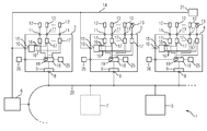
- a plant 1 shown in the figure comprises a plurality of heating control and / or regulating devices 2, 3, 4, a higher-level control and / or regulating device 5 for the heating control and / or regulating devices 2, 3, 4, further components which is shown for simplicity only a single component 6, and optionally an energy management system 7, all of these components are connected to a communication system 20 and can communicate with each other here.
- the communication system 20 is preferably an open industrial communication system, such as a computer. PROFIBUS or PROFINET.
- Each of the heating control and / or regulating devices 2, 3, 4 has for this purpose a communication interface 8 and a communication unit 9. Furthermore, each of the Heating control and / or regulating devices 2, 3, 4 a power input 10 and a plurality (eg nine) power outputs 11 on. In addition, the units 2, 3, 4 not yet shown further communication interfaces and / or power supply interfaces for internal power supply of the units 2, 3, 4 have.
- a heating element 12 in particular in each case a radiant heater, or alternatively a fan drive 13 (see, for example, the Schuungs Kunststoffungs- and / or -regelungs soliciten 3 and 4), electrically connected or connected.
- All of the power inputs 10 and the further system component 6 are electrically connected to an on-board power supply network 14 (e.g., rated at 400Vac) for powering the heater elements 12 and the fan drive 13, respectively.
- the power supply network 14 is in turn fed from a network 21 of an energy supplier.
- Each of the heating control and / or regulating devices 2, 3, 4 has a power distribution device 15 with line protection elements, not shown in more detail, which is electrically connected on the input side to the power input 10 and on the output side via a respective branch 16 electrically connected to the power outputs 11 supply electrical power from the power supply network 14.
- a switching element 17 is connected in each case.
- a semiconductor switch for example a so-called "solid state relay”
- an electromechanical contactor is used.
- the switching elements 17 are integrated into the Schuungs Kunststoffungs- and / or -regelungs Rheinen 2, 3, 4, that is enclosed by the housing, but it can also be around separate (ie not integrated into the housing) switching elements act.
- Each of the heating control and / or regulating devices 2, 3, 4 furthermore has a control and / or regulating unit 18.
- the control unit 18 is arranged to control and / or regulate the switching state of the switching elements 17 in response to control commands (e.g., enable commands, shutdown commands) and heating power setpoints.
- control commands e.g., enable commands, shutdown commands
- the setpoints may, for example, be in the form of absolute setpoints or setpoints related to a maximum power.
- the power may relate, for example, to a heat output to be output or a received electric power of heating elements.
- control signals for the switching elements 17 are then derived in the heating control and / or regulation device 2, 3, 4 with the aid of a predetermined control and / or regulation algorithm.
- the setpoint values can already be present in the form of pulse packets or percentages at half-waves per unit of time (for example per second), from which direct drive signals for the switching elements can then be derived in the control and / or regulating unit 18.
- the switching states of the switching elements 17 and thus the heating powers of the heating elements 12 are then controlled or regulated via the control signals.
- the control of the switching elements 17 and thus the control or regulation of the switching state or the heating power can be done for example with a phase control or a half-wave control.
- the communication unit 9 is set up in such a way that it commands specific commands for the respective unit 2, 3, 4 (eg commands for connecting or disconnecting the heating elements 12) or from the power supply network 14) and nominal values for the heating power via the communication interface 8 receives and transfers to the control and / or regulating unit 18.
- control and / or regulating unit 18 is set up in such a manner that it controls the switching state of the switching element 17 for the fan drive 13 in response to control commands (eg commands for switching on or off the fan drive 13 to and from the power supply network 14) and optionally also controlled by setpoint values for the drive power of the fan drive 13 and / or controls.
- control commands eg commands for switching on or off the fan drive 13 to and from the power supply network 14
- setpoint values for the drive power of the fan drive 13 and / or controls optionally also controlled by setpoint values for the drive power of the fan drive 13 and / or controls.
- the Schuungs horrids- and / or -regels wornen 2, 3, 4 are shown in the figure in an embodiment as independently operating compact devices, each with its own housing.
- the heating control and / or regulation devices 2, 3, 4 may also have a modular construction and in turn consist of several modules, such as e.g. a communication and control module as well as a plurality of power modules with a fundamentally similar construction to the heating control and / or regulation devices 2, 3, 4.
- the communication and control module serves as an interface to the communication system 20 and controls the power modules via a further communication system, which may also be a proprietary communication system.
- the heating control and / or regulating devices 2, 3, 4 receive from the higher-level control and / or regulating device 5 via the communication system 20 supply and shutdown commands for connecting or disconnecting the heating elements 12 and the fan 13 to or from the power supply network 14 and the setpoint values for the heating power of the heating elements 12, optionally also for the performance of the fan drive 13th
- the heating control and / or regulating devices 2, 3, 4 furthermore have a memory 25 in which characteristic parameters are stored for the heating elements 12 and, if present, the fan drive 13.
- the characteristic parameters include one or more of the following information about the heating elements or fan drives: type, rated power, rated current, rated voltage.
- the heating control and / or regulating devices 2, 3, 4 are designed for this purpose in such a way that they interrogate the characteristic parameters during a configuration or commissioning and store them in the memory 25.
- the control and / or regulating unit 18 comprises a calculation unit 19 which is set up in such a way that it determines values for an energy consumption and / or an actual power consumption of the heating elements 12 and, if present, the fan drive 13 without the use of measured values of electric currents characteristic parameters and based on values of control and / or regulation variables for the control and / or regulation of the heating power of the heating elements 12 and - if available - the fan drive 13 determined.
- the determination of the values is done without using measurements of any electrical quantities, i. solely on the basis of the characteristic parameters and values of control and / or regulation variables.
- the accuracy of the determined values of the energy consumption and / or the power consumption can be optionally improved with relatively little effort by the control and / or regulating units 18 with a voltage measuring device 26 for measurement on the heating elements 12 - and if present on the fan drive 13 - connected voltages or for measuring the voltage of the power supply network 14 and is designed such that it improves the accuracy of the determined values of energy consumption and / or the current power consumption with the voltage measured values.
- the communication unit 9 and the communication interface 8 then serve to transmit the determined energy consumption and / or the determined power consumption to the higher-level control and / or regulating device 5 and / or - if present - to the energy management system 7.
- the higher-level control and / or regulating device 5, or if present the energy management system 7, is also designed such that it determines the power consumption of the heating elements 12 over a longer period of time (eg a work cycle or a working day) and by an analysis of the temporal Progressive recommendations for an optimization of the system 1 outputs. For example, a time average of the power consumption can be determined, compared with a rated power of the heating elements and when exceeding and / or falling below the rated power by a predetermined threshold value, a signal can be generated.
- each of the heating control and / or regulating devices 2, 3, 4 by the respective calculation unit 19 based on the characteristic parameters of the heating elements 12, preferably also the fan drives 13, and based on values of control and / or Control variables for the control and / or regulation of the heating power of the heating elements 12, preferably also the performance of the fan drives 13, determines their energy consumption and / or power consumption and the communication system 20 to the higher-level control and / or regulating device 5, if available also to the Energy management system 7, transmitted.
- a nominal power Pn of each heating element 12 with applied rated voltage eg 230 Vac
- a type factor T (S) are stored in the memory 25, which depends on the type of the heating element 12 and the desired value for the heating power (in% of the nominal power Pn).
- the type factor takes into account the non-linearity, depending on the particular type of heating element, between the setpoint and the actual power consumption or the actual electrical power consumed.
- the type factor (TS) can be present, for example, in the form of a family of characteristic lines for different setpoint values S in each case.
- the voltage applied to the heating elements 12, preferably also to the fan drives 13, or the voltage of the common voltage supply 14 can be measured and the accuracy of the determined values of the energy consumption and / or the power consumption can be improved with the measured voltage values.
- the heating powers of the heating elements 12, preferably also the fan drives 13, are then controlled and / or regulated by the higher-level control and / or regulating device 5 on the basis of the received energy consumption and / or power consumption. This can also take place in cooperation with the energy management system 7, which supply or shutdown commands for the heating elements 12, preferably also for the fan drives 13, or limits for the absorbed power or energy consumption via the communication system 20 to the higher-level control and / or regulating device 5 transmitted. This then generates the control commands and setpoint values for the heating power of the heating elements 12, preferably also for the power of the fan drives 13, as a function of the values received by the energy management system 7.
- a time average of the power consumption is determined, compared with a rated power of the heating elements 12 and at a (undershooting) of the rated power by a predetermined limit, the heating elements 12 are replaced by heating elements with a higher (lower) rated power. It can thus be easily detected undersizing (oversizing) of heating elements and carried out a replacement by more suitable heating elements.
- a corresponding procedure is of course also possible with respect to the fan drives 13.
- the energy consumption and / or the power consumption is thus without measuring electrical currents, preferably without measuring any electrical variables, by a calculation based on characteristic parameters of the heating elements 12 (preferably also the fan drives 13) and based on values of control and / or regulation variables for the control and / or regulation of the heating power of the heating elements 12 (preferably also the power of the fan drives 13) determined. It is therefore only a small or no consuming and expensive measuring device necessary.
Landscapes
- Control Of Temperature (AREA)
- Air Conditioning Control Device (AREA)
- Supply And Distribution Of Alternating Current (AREA)
- Control Of Resistance Heating (AREA)
Applications Claiming Priority (1)
| Application Number | Priority Date | Filing Date | Title |
|---|---|---|---|
| DE102014203667.4A DE102014203667A1 (de) | 2014-02-28 | 2014-02-28 | Verfahren zum Betreiben einer Anlage mit zumindest einer Heizungssteuerungs- und/oder -regelungseinrichtung, Heizungssteuerungs- und/oder -regelungseinrichtung sowie Anlage |
Publications (3)
| Publication Number | Publication Date |
|---|---|
| EP2913734A2 true EP2913734A2 (fr) | 2015-09-02 |
| EP2913734A3 EP2913734A3 (fr) | 2015-12-23 |
| EP2913734B1 EP2913734B1 (fr) | 2019-03-27 |
Family
ID=52669398
Family Applications (1)
| Application Number | Title | Priority Date | Filing Date |
|---|---|---|---|
| EP15154354.3A Active EP2913734B1 (fr) | 2014-02-28 | 2015-02-09 | Dispositif de fonctionnement d'une installation ayant au moins un dispositif de réglage et/ou de commande de chauffage, dispositif de réglage et/ou de commande de chauffage et installation |
Country Status (5)
| Country | Link |
|---|---|
| US (1) | US9980319B2 (fr) |
| EP (1) | EP2913734B1 (fr) |
| CN (1) | CN104883752B (fr) |
| DE (1) | DE102014203667A1 (fr) |
| TW (1) | TW201535110A (fr) |
Cited By (1)
| Publication number | Priority date | Publication date | Assignee | Title |
|---|---|---|---|---|
| EP3706018A1 (fr) * | 2019-03-07 | 2020-09-09 | Siemens Aktiengesellschaft | Dispositif et procédé de configuration d'un système technique |
Families Citing this family (4)
| Publication number | Priority date | Publication date | Assignee | Title |
|---|---|---|---|---|
| DE102014203667A1 (de) | 2014-02-28 | 2015-09-03 | Siemens Aktiengesellschaft | Verfahren zum Betreiben einer Anlage mit zumindest einer Heizungssteuerungs- und/oder -regelungseinrichtung, Heizungssteuerungs- und/oder -regelungseinrichtung sowie Anlage |
| CN108141928B (zh) * | 2015-10-23 | 2020-11-17 | 三菱电机株式会社 | 感应加热烹调器 |
| CN105353709A (zh) * | 2015-12-04 | 2016-02-24 | 重庆臻远电气有限公司 | 防雷的开关柜监控设备 |
| CN105353708A (zh) * | 2015-12-04 | 2016-02-24 | 重庆臻远电气有限公司 | 开关柜监控设备 |
Family Cites Families (13)
| Publication number | Priority date | Publication date | Assignee | Title |
|---|---|---|---|---|
| FR2621406B1 (fr) * | 1987-10-02 | 1990-01-05 | Saint Gobain Vitrage | Commande de four electrique industriel |
| JPH0241826A (ja) * | 1988-07-28 | 1990-02-13 | Fanuc Ltd | ワイヤ張力制御方式 |
| FR2649555A1 (fr) * | 1989-07-10 | 1991-01-11 | Eurotherm Automation Sa | Procede et dispositif de commande de l'alimentation de charges, adaptes pour reduire les fluctuations de tension sur le reseau |
| US5023430A (en) * | 1989-09-08 | 1991-06-11 | Environwear, Inc. | Hybrid electronic control system and method for cold weather garment |
| US5280434A (en) * | 1991-07-01 | 1994-01-18 | Thermoforming Technologies, Inc. | Heating system for thermoforming |
| DE19529313A1 (de) * | 1995-08-09 | 1997-02-13 | Siemens Ag | Betriebsverfahren für eine programmgesteuerte Recheneinheit zur Steuerung von Strahlerfeldern insbesondere von Thermoformmaschinen |
| KR100347097B1 (ko) * | 1999-10-16 | 2002-08-03 | 엘지전자주식회사 | 조리기의 부품 이상동작감지방법 |
| JP5041016B2 (ja) * | 2010-03-01 | 2012-10-03 | 東京エレクトロン株式会社 | 熱処理装置、熱処理方法及び記憶媒体 |
| US8525083B2 (en) * | 2010-09-17 | 2013-09-03 | General Electric Company | Water heater with power consumption reporting |
| EP2625465A2 (fr) * | 2010-10-08 | 2013-08-14 | BSH Bosch und Siemens Hausgeräte GmbH | Système pour appareils ménagers |
| CN102090772A (zh) * | 2010-12-21 | 2011-06-15 | 刘建波 | 一种新型无线电吹风 |
| DE202013003006U1 (de) * | 2013-03-28 | 2013-04-25 | Siemens Aktiengesellschaft | Heizungssteuerungsgerät |
| DE102014203667A1 (de) | 2014-02-28 | 2015-09-03 | Siemens Aktiengesellschaft | Verfahren zum Betreiben einer Anlage mit zumindest einer Heizungssteuerungs- und/oder -regelungseinrichtung, Heizungssteuerungs- und/oder -regelungseinrichtung sowie Anlage |
-
2014
- 2014-02-28 DE DE102014203667.4A patent/DE102014203667A1/de not_active Ceased
-
2015
- 2015-02-09 CN CN201510067564.1A patent/CN104883752B/zh not_active Expired - Fee Related
- 2015-02-09 EP EP15154354.3A patent/EP2913734B1/fr active Active
- 2015-02-10 TW TW104104327A patent/TW201535110A/zh unknown
- 2015-03-02 US US14/635,283 patent/US9980319B2/en not_active Expired - Fee Related
Non-Patent Citations (1)
| Title |
|---|
| None |
Cited By (1)
| Publication number | Priority date | Publication date | Assignee | Title |
|---|---|---|---|---|
| EP3706018A1 (fr) * | 2019-03-07 | 2020-09-09 | Siemens Aktiengesellschaft | Dispositif et procédé de configuration d'un système technique |
Also Published As
| Publication number | Publication date |
|---|---|
| DE102014203667A1 (de) | 2015-09-03 |
| EP2913734B1 (fr) | 2019-03-27 |
| US20150250023A1 (en) | 2015-09-03 |
| CN104883752B (zh) | 2020-01-07 |
| CN104883752A (zh) | 2015-09-02 |
| US9980319B2 (en) | 2018-05-22 |
| TW201535110A (zh) | 2015-09-16 |
| EP2913734A3 (fr) | 2015-12-23 |
Similar Documents
| Publication | Publication Date | Title |
|---|---|---|
| EP2916191B1 (fr) | Appareil de régulation et/ou de commande de chauffage | |
| EP2913734B1 (fr) | Dispositif de fonctionnement d'une installation ayant au moins un dispositif de réglage et/ou de commande de chauffage, dispositif de réglage et/ou de commande de chauffage et installation | |
| EP2913735B1 (fr) | Module de puissance et module d'interface pour réglage de chauffage | |
| EP2192457B1 (fr) | Elément d'automatisation pour une installation d'automatisation industrielle et procédé d'activation d'un état de fonctionnement | |
| DE202013003006U1 (de) | Heizungssteuerungsgerät | |
| EP2192458B1 (fr) | Dispositif de commande et procédé de gestion de l'énergie d'une installation d'automatisation industrielle | |
| EP2555074B1 (fr) | Procédé de réglage en fonction du besoin d'une installation de refroidissement et/ou de chauffage pour un objet comprenant au moins une unité d'utilisation | |
| EP2982018A1 (fr) | Unité d'alimentation en courant et procédé de montage en parallèle de plusieurs unités d'alimentation en courant | |
| DE102008051199A1 (de) | Verfahren und Anordnung zur Lüfteransteuerung | |
| DE19842043B4 (de) | Verfahren zur automatischen und verbraucherorientierten Minimierung des Gesamtstromverbrauchs und der Leistungsspitze einer Gruppe von an einem Leistungsversorgungsnetz angeschlossenen einzelnen elektrischen Verbrauchern | |
| EP1178551A2 (fr) | Procédé pour contrôler un système de pile à combustible | |
| EP2624428A1 (fr) | Alimentation électrique C.C. modulaire avec des sorties indépendantes | |
| EP3440976B1 (fr) | Appareil électroménager entraîné par un accumulateur ainsi que procédé de fonctionnement d'un appareil électroménager | |
| EP2594858A1 (fr) | Procédé et système de télécommande de climatisations individuelles décentralisées sans interface de mise en réseau | |
| EP2953420A1 (fr) | Installation de chauffage electrique par accumulation | |
| DE102023103643A1 (de) | Vorrichtung für ein Heizsystem sowie Heizsystem und Verfahren zu dessen Betrieb | |
| DE19651484A1 (de) | Verfahren zur Leistungsaufnahmeoptimierung eines Verbundes elektrisch geheizter bzw. gekühlter Verbraucher | |
| DE102021101589A1 (de) | Steuersystem zur optimierten Elektroenergienutzung | |
| DE102015015941B4 (de) | Umschaltbare Analog-Schnittstelle bei Feldgeräten | |
| DE59508258C5 (de) | Elektrisches Heizgerät und Verfahren zu dessen Betreiben | |
| EP4502488A1 (fr) | Dispositif de commutation, installation domotique et procédé de fonctionnement d'un dispositif de chauffage | |
| DE102012111046A1 (de) | Verfahren zum Begrenzen einer maximalen Leistungsaufnahme einer komplexen Produktionsmaschine, insbesondere einer Spritzgießmaschine | |
| EP0697084A1 (fr) | Appareil de chauffage electrique a accumulation | |
| DE102009023694A1 (de) | Gerät mit hoher Leistungsaufnahme, insbesondere Frequenzumformer, Reihenanordnung, Energieverteilungssystem, Sicherung und Kühlsystem | |
| EP4443820A1 (fr) | Commutateur ethernet avec alimentation intégrée |
Legal Events
| Date | Code | Title | Description |
|---|---|---|---|
| PUAI | Public reference made under article 153(3) epc to a published international application that has entered the european phase |
Free format text: ORIGINAL CODE: 0009012 |
|
| AK | Designated contracting states |
Kind code of ref document: A2 Designated state(s): AL AT BE BG CH CY CZ DE DK EE ES FI FR GB GR HR HU IE IS IT LI LT LU LV MC MK MT NL NO PL PT RO RS SE SI SK SM TR |
|
| AX | Request for extension of the european patent |
Extension state: BA ME |
|
| PUAL | Search report despatched |
Free format text: ORIGINAL CODE: 0009013 |
|
| AK | Designated contracting states |
Kind code of ref document: A3 Designated state(s): AL AT BE BG CH CY CZ DE DK EE ES FI FR GB GR HR HU IE IS IT LI LT LU LV MC MK MT NL NO PL PT RO RS SE SI SK SM TR |
|
| AX | Request for extension of the european patent |
Extension state: BA ME |
|
| RIC1 | Information provided on ipc code assigned before grant |
Ipc: H05B 1/02 20060101AFI20151117BHEP |
|
| 17P | Request for examination filed |
Effective date: 20160621 |
|
| RBV | Designated contracting states (corrected) |
Designated state(s): AL AT BE BG CH CY CZ DE DK EE ES FI FR GB GR HR HU IE IS IT LI LT LU LV MC MK MT NL NO PL PT RO RS SE SI SK SM TR |
|
| R17P | Request for examination filed (corrected) |
Effective date: 20160621 |
|
| RIN1 | Information on inventor provided before grant (corrected) |
Inventor name: SCHMIDT, BERNHARD Inventor name: SCHNEIDER, REINHARD Inventor name: STOLL, JUERGEN Inventor name: BACH, CHRISTINE Inventor name: INDEFREY, KLAUS |
|
| STAA | Information on the status of an ep patent application or granted ep patent |
Free format text: STATUS: EXAMINATION IS IN PROGRESS |
|
| 17Q | First examination report despatched |
Effective date: 20170630 |
|
| RAP1 | Party data changed (applicant data changed or rights of an application transferred) |
Owner name: SIEMENS AKTIENGESELLSCHAFT |
|
| GRAP | Despatch of communication of intention to grant a patent |
Free format text: ORIGINAL CODE: EPIDOSNIGR1 |
|
| STAA | Information on the status of an ep patent application or granted ep patent |
Free format text: STATUS: GRANT OF PATENT IS INTENDED |
|
| INTG | Intention to grant announced |
Effective date: 20180926 |
|
| GRAS | Grant fee paid |
Free format text: ORIGINAL CODE: EPIDOSNIGR3 |
|
| GRAA | (expected) grant |
Free format text: ORIGINAL CODE: 0009210 |
|
| STAA | Information on the status of an ep patent application or granted ep patent |
Free format text: STATUS: THE PATENT HAS BEEN GRANTED |
|
| AK | Designated contracting states |
Kind code of ref document: B1 Designated state(s): AL AT BE BG CH CY CZ DE DK EE ES FI FR GB GR HR HU IE IS IT LI LT LU LV MC MK MT NL NO PL PT RO RS SE SI SK SM TR |
|
| REG | Reference to a national code |
Ref country code: GB Ref legal event code: FG4D Free format text: NOT ENGLISH |
|
| REG | Reference to a national code |
Ref country code: CH Ref legal event code: EP |
|
| REG | Reference to a national code |
Ref country code: AT Ref legal event code: REF Ref document number: 1114549 Country of ref document: AT Kind code of ref document: T Effective date: 20190415 |
|
| REG | Reference to a national code |
Ref country code: IE Ref legal event code: FG4D Free format text: LANGUAGE OF EP DOCUMENT: GERMAN |
|
| REG | Reference to a national code |
Ref country code: DE Ref legal event code: R096 Ref document number: 502015008444 Country of ref document: DE |
|
| PG25 | Lapsed in a contracting state [announced via postgrant information from national office to epo] |
Ref country code: NO Free format text: LAPSE BECAUSE OF FAILURE TO SUBMIT A TRANSLATION OF THE DESCRIPTION OR TO PAY THE FEE WITHIN THE PRESCRIBED TIME-LIMIT Effective date: 20190627 Ref country code: FI Free format text: LAPSE BECAUSE OF FAILURE TO SUBMIT A TRANSLATION OF THE DESCRIPTION OR TO PAY THE FEE WITHIN THE PRESCRIBED TIME-LIMIT Effective date: 20190327 Ref country code: SE Free format text: LAPSE BECAUSE OF FAILURE TO SUBMIT A TRANSLATION OF THE DESCRIPTION OR TO PAY THE FEE WITHIN THE PRESCRIBED TIME-LIMIT Effective date: 20190327 Ref country code: LT Free format text: LAPSE BECAUSE OF FAILURE TO SUBMIT A TRANSLATION OF THE DESCRIPTION OR TO PAY THE FEE WITHIN THE PRESCRIBED TIME-LIMIT Effective date: 20190327 |
|
| REG | Reference to a national code |
Ref country code: NL Ref legal event code: MP Effective date: 20190327 |
|
| PG25 | Lapsed in a contracting state [announced via postgrant information from national office to epo] |
Ref country code: LV Free format text: LAPSE BECAUSE OF FAILURE TO SUBMIT A TRANSLATION OF THE DESCRIPTION OR TO PAY THE FEE WITHIN THE PRESCRIBED TIME-LIMIT Effective date: 20190327 Ref country code: NL Free format text: LAPSE BECAUSE OF FAILURE TO SUBMIT A TRANSLATION OF THE DESCRIPTION OR TO PAY THE FEE WITHIN THE PRESCRIBED TIME-LIMIT Effective date: 20190327 Ref country code: HR Free format text: LAPSE BECAUSE OF FAILURE TO SUBMIT A TRANSLATION OF THE DESCRIPTION OR TO PAY THE FEE WITHIN THE PRESCRIBED TIME-LIMIT Effective date: 20190327 Ref country code: GR Free format text: LAPSE BECAUSE OF FAILURE TO SUBMIT A TRANSLATION OF THE DESCRIPTION OR TO PAY THE FEE WITHIN THE PRESCRIBED TIME-LIMIT Effective date: 20190628 Ref country code: BG Free format text: LAPSE BECAUSE OF FAILURE TO SUBMIT A TRANSLATION OF THE DESCRIPTION OR TO PAY THE FEE WITHIN THE PRESCRIBED TIME-LIMIT Effective date: 20190627 Ref country code: RS Free format text: LAPSE BECAUSE OF FAILURE TO SUBMIT A TRANSLATION OF THE DESCRIPTION OR TO PAY THE FEE WITHIN THE PRESCRIBED TIME-LIMIT Effective date: 20190327 |
|
| PG25 | Lapsed in a contracting state [announced via postgrant information from national office to epo] |
Ref country code: EE Free format text: LAPSE BECAUSE OF FAILURE TO SUBMIT A TRANSLATION OF THE DESCRIPTION OR TO PAY THE FEE WITHIN THE PRESCRIBED TIME-LIMIT Effective date: 20190327 Ref country code: ES Free format text: LAPSE BECAUSE OF FAILURE TO SUBMIT A TRANSLATION OF THE DESCRIPTION OR TO PAY THE FEE WITHIN THE PRESCRIBED TIME-LIMIT Effective date: 20190327 Ref country code: RO Free format text: LAPSE BECAUSE OF FAILURE TO SUBMIT A TRANSLATION OF THE DESCRIPTION OR TO PAY THE FEE WITHIN THE PRESCRIBED TIME-LIMIT Effective date: 20190327 Ref country code: CZ Free format text: LAPSE BECAUSE OF FAILURE TO SUBMIT A TRANSLATION OF THE DESCRIPTION OR TO PAY THE FEE WITHIN THE PRESCRIBED TIME-LIMIT Effective date: 20190327 Ref country code: PT Free format text: LAPSE BECAUSE OF FAILURE TO SUBMIT A TRANSLATION OF THE DESCRIPTION OR TO PAY THE FEE WITHIN THE PRESCRIBED TIME-LIMIT Effective date: 20190727 Ref country code: SK Free format text: LAPSE BECAUSE OF FAILURE TO SUBMIT A TRANSLATION OF THE DESCRIPTION OR TO PAY THE FEE WITHIN THE PRESCRIBED TIME-LIMIT Effective date: 20190327 Ref country code: AL Free format text: LAPSE BECAUSE OF FAILURE TO SUBMIT A TRANSLATION OF THE DESCRIPTION OR TO PAY THE FEE WITHIN THE PRESCRIBED TIME-LIMIT Effective date: 20190327 |
|
| PG25 | Lapsed in a contracting state [announced via postgrant information from national office to epo] |
Ref country code: PL Free format text: LAPSE BECAUSE OF FAILURE TO SUBMIT A TRANSLATION OF THE DESCRIPTION OR TO PAY THE FEE WITHIN THE PRESCRIBED TIME-LIMIT Effective date: 20190327 Ref country code: SM Free format text: LAPSE BECAUSE OF FAILURE TO SUBMIT A TRANSLATION OF THE DESCRIPTION OR TO PAY THE FEE WITHIN THE PRESCRIBED TIME-LIMIT Effective date: 20190327 |
|
| PG25 | Lapsed in a contracting state [announced via postgrant information from national office to epo] |
Ref country code: IS Free format text: LAPSE BECAUSE OF FAILURE TO SUBMIT A TRANSLATION OF THE DESCRIPTION OR TO PAY THE FEE WITHIN THE PRESCRIBED TIME-LIMIT Effective date: 20190727 |
|
| REG | Reference to a national code |
Ref country code: DE Ref legal event code: R097 Ref document number: 502015008444 Country of ref document: DE |
|
| PG25 | Lapsed in a contracting state [announced via postgrant information from national office to epo] |
Ref country code: DK Free format text: LAPSE BECAUSE OF FAILURE TO SUBMIT A TRANSLATION OF THE DESCRIPTION OR TO PAY THE FEE WITHIN THE PRESCRIBED TIME-LIMIT Effective date: 20190327 |
|
| PLBE | No opposition filed within time limit |
Free format text: ORIGINAL CODE: 0009261 |
|
| STAA | Information on the status of an ep patent application or granted ep patent |
Free format text: STATUS: NO OPPOSITION FILED WITHIN TIME LIMIT |
|
| PG25 | Lapsed in a contracting state [announced via postgrant information from national office to epo] |
Ref country code: SI Free format text: LAPSE BECAUSE OF FAILURE TO SUBMIT A TRANSLATION OF THE DESCRIPTION OR TO PAY THE FEE WITHIN THE PRESCRIBED TIME-LIMIT Effective date: 20190327 |
|
| 26N | No opposition filed |
Effective date: 20200103 |
|
| PG25 | Lapsed in a contracting state [announced via postgrant information from national office to epo] |
Ref country code: TR Free format text: LAPSE BECAUSE OF FAILURE TO SUBMIT A TRANSLATION OF THE DESCRIPTION OR TO PAY THE FEE WITHIN THE PRESCRIBED TIME-LIMIT Effective date: 20190327 |
|
| REG | Reference to a national code |
Ref country code: CH Ref legal event code: PL |
|
| GBPC | Gb: european patent ceased through non-payment of renewal fee |
Effective date: 20200209 |
|
| REG | Reference to a national code |
Ref country code: BE Ref legal event code: MM Effective date: 20200229 |
|
| PG25 | Lapsed in a contracting state [announced via postgrant information from national office to epo] |
Ref country code: MC Free format text: LAPSE BECAUSE OF FAILURE TO SUBMIT A TRANSLATION OF THE DESCRIPTION OR TO PAY THE FEE WITHIN THE PRESCRIBED TIME-LIMIT Effective date: 20190327 Ref country code: LU Free format text: LAPSE BECAUSE OF NON-PAYMENT OF DUE FEES Effective date: 20200209 |
|
| PG25 | Lapsed in a contracting state [announced via postgrant information from national office to epo] |
Ref country code: LI Free format text: LAPSE BECAUSE OF NON-PAYMENT OF DUE FEES Effective date: 20200229 Ref country code: CH Free format text: LAPSE BECAUSE OF NON-PAYMENT OF DUE FEES Effective date: 20200229 |
|
| PG25 | Lapsed in a contracting state [announced via postgrant information from national office to epo] |
Ref country code: IE Free format text: LAPSE BECAUSE OF NON-PAYMENT OF DUE FEES Effective date: 20200209 Ref country code: GB Free format text: LAPSE BECAUSE OF NON-PAYMENT OF DUE FEES Effective date: 20200209 |
|
| PG25 | Lapsed in a contracting state [announced via postgrant information from national office to epo] |
Ref country code: BE Free format text: LAPSE BECAUSE OF NON-PAYMENT OF DUE FEES Effective date: 20200229 |
|
| REG | Reference to a national code |
Ref country code: AT Ref legal event code: MM01 Ref document number: 1114549 Country of ref document: AT Kind code of ref document: T Effective date: 20200209 |
|
| PG25 | Lapsed in a contracting state [announced via postgrant information from national office to epo] |
Ref country code: AT Free format text: LAPSE BECAUSE OF NON-PAYMENT OF DUE FEES Effective date: 20200209 |
|
| PG25 | Lapsed in a contracting state [announced via postgrant information from national office to epo] |
Ref country code: MT Free format text: LAPSE BECAUSE OF FAILURE TO SUBMIT A TRANSLATION OF THE DESCRIPTION OR TO PAY THE FEE WITHIN THE PRESCRIBED TIME-LIMIT Effective date: 20190327 Ref country code: CY Free format text: LAPSE BECAUSE OF FAILURE TO SUBMIT A TRANSLATION OF THE DESCRIPTION OR TO PAY THE FEE WITHIN THE PRESCRIBED TIME-LIMIT Effective date: 20190327 |
|
| PG25 | Lapsed in a contracting state [announced via postgrant information from national office to epo] |
Ref country code: MK Free format text: LAPSE BECAUSE OF FAILURE TO SUBMIT A TRANSLATION OF THE DESCRIPTION OR TO PAY THE FEE WITHIN THE PRESCRIBED TIME-LIMIT Effective date: 20190327 |
|
| PGFP | Annual fee paid to national office [announced via postgrant information from national office to epo] |
Ref country code: FR Payment date: 20230221 Year of fee payment: 9 |
|
| PGFP | Annual fee paid to national office [announced via postgrant information from national office to epo] |
Ref country code: IT Payment date: 20230221 Year of fee payment: 9 Ref country code: DE Payment date: 20220620 Year of fee payment: 9 |
|
| REG | Reference to a national code |
Ref country code: DE Ref legal event code: R119 Ref document number: 502015008444 Country of ref document: DE |
|
| PG25 | Lapsed in a contracting state [announced via postgrant information from national office to epo] |
Ref country code: DE Free format text: LAPSE BECAUSE OF NON-PAYMENT OF DUE FEES Effective date: 20240903 |
|
| PG25 | Lapsed in a contracting state [announced via postgrant information from national office to epo] |
Ref country code: FR Free format text: LAPSE BECAUSE OF NON-PAYMENT OF DUE FEES Effective date: 20240229 |
|
| PG25 | Lapsed in a contracting state [announced via postgrant information from national office to epo] |
Ref country code: FR Free format text: LAPSE BECAUSE OF NON-PAYMENT OF DUE FEES Effective date: 20240229 Ref country code: DE Free format text: LAPSE BECAUSE OF NON-PAYMENT OF DUE FEES Effective date: 20240903 |
|
| PG25 | Lapsed in a contracting state [announced via postgrant information from national office to epo] |
Ref country code: IT Free format text: LAPSE BECAUSE OF NON-PAYMENT OF DUE FEES Effective date: 20240209 |