EP2914323B1 - Intumask-anordnung - Google Patents
Intumask-anordnung Download PDFInfo
- Publication number
- EP2914323B1 EP2914323B1 EP13850523.5A EP13850523A EP2914323B1 EP 2914323 B1 EP2914323 B1 EP 2914323B1 EP 13850523 A EP13850523 A EP 13850523A EP 2914323 B1 EP2914323 B1 EP 2914323B1
- Authority
- EP
- European Patent Office
- Prior art keywords
- tubus
- olt
- laryngeal mask
- integrated
- balloon
- Prior art date
- Legal status (The legal status is an assumption and is not a legal conclusion. Google has not performed a legal analysis and makes no representation as to the accuracy of the status listed.)
- Not-in-force
Links
- 210000003437 trachea Anatomy 0.000 claims description 20
- 238000007789 sealing Methods 0.000 claims description 18
- 210000003238 esophagus Anatomy 0.000 claims description 16
- 239000012530 fluid Substances 0.000 claims description 16
- 238000009423 ventilation Methods 0.000 claims description 11
- 230000002093 peripheral effect Effects 0.000 claims description 10
- 238000011109 contamination Methods 0.000 claims description 8
- 210000001260 vocal cord Anatomy 0.000 claims description 7
- 239000013013 elastic material Substances 0.000 claims description 6
- 239000000463 material Substances 0.000 claims description 6
- 230000000087 stabilizing effect Effects 0.000 claims description 5
- 238000000034 method Methods 0.000 description 98
- 210000000867 larynx Anatomy 0.000 description 11
- 238000003780 insertion Methods 0.000 description 7
- 230000037431 insertion Effects 0.000 description 7
- 238000004891 communication Methods 0.000 description 6
- 230000000873 masking effect Effects 0.000 description 3
- 230000000712 assembly Effects 0.000 description 2
- 238000000429 assembly Methods 0.000 description 2
- 230000000977 initiatory effect Effects 0.000 description 2
- 210000004072 lung Anatomy 0.000 description 2
- 238000004519 manufacturing process Methods 0.000 description 2
- 238000000926 separation method Methods 0.000 description 2
- 230000004913 activation Effects 0.000 description 1
- 239000000560 biocompatible material Substances 0.000 description 1
- 230000015572 biosynthetic process Effects 0.000 description 1
- 210000000621 bronchi Anatomy 0.000 description 1
- 230000001419 dependent effect Effects 0.000 description 1
- 230000000694 effects Effects 0.000 description 1
- 239000000806 elastomer Substances 0.000 description 1
- 229920001971 elastomer Polymers 0.000 description 1
- 210000002409 epiglottis Anatomy 0.000 description 1
- 239000000835 fiber Substances 0.000 description 1
- 239000011796 hollow space material Substances 0.000 description 1
- 208000015181 infectious disease Diseases 0.000 description 1
- 230000010354 integration Effects 0.000 description 1
- 230000029058 respiratory gaseous exchange Effects 0.000 description 1
- 238000001356 surgical procedure Methods 0.000 description 1
- 210000000115 thoracic cavity Anatomy 0.000 description 1
- 238000002627 tracheal intubation Methods 0.000 description 1
- 238000011144 upstream manufacturing Methods 0.000 description 1
Images


Classifications
-
- A—HUMAN NECESSITIES
- A61—MEDICAL OR VETERINARY SCIENCE; HYGIENE
- A61M—DEVICES FOR INTRODUCING MEDIA INTO, OR ONTO, THE BODY; DEVICES FOR TRANSDUCING BODY MEDIA OR FOR TAKING MEDIA FROM THE BODY; DEVICES FOR PRODUCING OR ENDING SLEEP OR STUPOR
- A61M16/00—Devices for influencing the respiratory system of patients by gas treatment, e.g. ventilators; Tracheal tubes
- A61M16/04—Tracheal tubes
- A61M16/0488—Mouthpieces; Means for guiding, securing or introducing the tubes
-
- A—HUMAN NECESSITIES
- A61—MEDICAL OR VETERINARY SCIENCE; HYGIENE
- A61B—DIAGNOSIS; SURGERY; IDENTIFICATION
- A61B1/00—Instruments for performing medical examinations of the interior of cavities or tubes of the body by visual or photographical inspection, e.g. endoscopes; Illuminating arrangements therefor
- A61B1/32—Devices for opening or enlarging the visual field, e.g. of a tube of the body
-
- A—HUMAN NECESSITIES
- A61—MEDICAL OR VETERINARY SCIENCE; HYGIENE
- A61M—DEVICES FOR INTRODUCING MEDIA INTO, OR ONTO, THE BODY; DEVICES FOR TRANSDUCING BODY MEDIA OR FOR TAKING MEDIA FROM THE BODY; DEVICES FOR PRODUCING OR ENDING SLEEP OR STUPOR
- A61M16/00—Devices for influencing the respiratory system of patients by gas treatment, e.g. ventilators; Tracheal tubes
- A61M16/04—Tracheal tubes
-
- A—HUMAN NECESSITIES
- A61—MEDICAL OR VETERINARY SCIENCE; HYGIENE
- A61M—DEVICES FOR INTRODUCING MEDIA INTO, OR ONTO, THE BODY; DEVICES FOR TRANSDUCING BODY MEDIA OR FOR TAKING MEDIA FROM THE BODY; DEVICES FOR PRODUCING OR ENDING SLEEP OR STUPOR
- A61M16/00—Devices for influencing the respiratory system of patients by gas treatment, e.g. ventilators; Tracheal tubes
- A61M16/04—Tracheal tubes
- A61M16/0402—Special features for tracheal tubes not otherwise provided for
- A61M16/0409—Special features for tracheal tubes not otherwise provided for with mean for closing the oesophagus
-
- A—HUMAN NECESSITIES
- A61—MEDICAL OR VETERINARY SCIENCE; HYGIENE
- A61M—DEVICES FOR INTRODUCING MEDIA INTO, OR ONTO, THE BODY; DEVICES FOR TRANSDUCING BODY MEDIA OR FOR TAKING MEDIA FROM THE BODY; DEVICES FOR PRODUCING OR ENDING SLEEP OR STUPOR
- A61M16/00—Devices for influencing the respiratory system of patients by gas treatment, e.g. ventilators; Tracheal tubes
- A61M16/04—Tracheal tubes
- A61M16/0434—Cuffs
- A61M16/044—External cuff pressure control or supply, e.g. synchronisation with respiration
-
- A—HUMAN NECESSITIES
- A61—MEDICAL OR VETERINARY SCIENCE; HYGIENE
- A61M—DEVICES FOR INTRODUCING MEDIA INTO, OR ONTO, THE BODY; DEVICES FOR TRANSDUCING BODY MEDIA OR FOR TAKING MEDIA FROM THE BODY; DEVICES FOR PRODUCING OR ENDING SLEEP OR STUPOR
- A61M16/00—Devices for influencing the respiratory system of patients by gas treatment, e.g. ventilators; Tracheal tubes
- A61M16/04—Tracheal tubes
- A61M16/0402—Special features for tracheal tubes not otherwise provided for
- A61M16/0425—Metal tubes
-
- A—HUMAN NECESSITIES
- A61—MEDICAL OR VETERINARY SCIENCE; HYGIENE
- A61M—DEVICES FOR INTRODUCING MEDIA INTO, OR ONTO, THE BODY; DEVICES FOR TRANSDUCING BODY MEDIA OR FOR TAKING MEDIA FROM THE BODY; DEVICES FOR PRODUCING OR ENDING SLEEP OR STUPOR
- A61M16/00—Devices for influencing the respiratory system of patients by gas treatment, e.g. ventilators; Tracheal tubes
- A61M16/04—Tracheal tubes
- A61M16/0434—Cuffs
Definitions
- This invention generally pertains to artificial airway assemblies.
- it relates to artificial airway assemblies in which the airway tube is designed for ease of function and placement, and for ensuring that the airway assembly is secured in the correct position.
- US patent application 2003192548 discloses a laryngeal mask tube which consists of a dual-airway tube, a mask with an inflatable bladder and an inflation indicator device.
- the dual-airway tube comprises a simplified primary tube and secondary tube integrally combined.
- the primary tube communicates with the mask to guide gas into the body of a patient and the secondary tube communicates between with the bladder and the inflation indicator device to inflate the bladder and monitor the inflation.
- two ribs are formed in the mask to prevent blockage of the primary tube, and a tongue is formed inside the bladder to prevent the bladder from folding and preventing a seal around the larynx. All of this ensures that the laryngeal mask airway is convenient and efficient to use.
- US patent application 2004089307 discloses an artificial airway device comprising a laryngo-pharyngeal mask which includes an expandable masking ring of roughly elliptical shape.
- the expandable mask sealingly surrounds the laryngeal inlet when expanded, to obstruct communication between the laryngeal inlet and the esophagus.
- One or more airway tubes connected to the mask provide for fluid flow to a portion of the mask facing the laryngeal inlet when the mask sealingly surrounds the laryngeal inlet.
- a gastro-tube connected to the mask is bonded along most of its length to the airway tube and provides a fluid flow-path to the surface of the mask facing the esophagus when the mask sealingly surrounds the laryngeal inlet.
- the distal end of the gastro tube passes through the masking ring at its narrower distal region where, when installed in a patient, it abuts against the esophagus; and the distal portion of the gastro tube flattens when the mask is deflated to facilitate smooth passage behind the larynx during insertion through the mouth and throat of the patient.
- US patent 4,681,094 discloses a laryngoscope comprising a disposable blade unit including two full length blades releasably interconnected along the length thereof to define a tubular passage.
- a reusable handle unit removably receives one end of the blade unit and retains the blades thereof.
- the blade unit includes an inflatable balloon expandable against the roof of the mouth to center an inserted laryngoscope and effect movement thereof against the tongue and epiglottis.
- a pair of suction channels are defined through the blade unit and communicated with the interior of the tubular passage at the leading end thereof.
- the handle unit includes means for communicating the balloon and suction passages with sources of positive and negative air pressure respectively.
- the handle unit also mounts illuminating means and a selectively usable adapter for accommodating a hand-manipulable air bag for emergency respiration directly through the laryngoscope.
- PCT application WO2004006746 discloses a device for the lateral separation of the air passages of patients or for single-lung ventilation during thoracic surgery.
- the device comprises a laryngeal mask, upstream of the larynx of the patient, in which a first tube is integrated for lung ventilation.
- the aim of the invention is to develop a device which enables the lateral separation of the air passages of the patient, or single-lung ventilation, in a safe and effective manner, and which enables the disadvantages of the double lumen tube used until now and the bronchus blocker available until now to be avoided.
- one such device comprises a second tube which can be introduced into the air passages via the first tube.
- US patent application 2007/0163597 discloses an over-tube which guides a device having an insertion section to be insereted into a body of a patient.
- GB patent application 2, 317,830 discloses a laryngeal mask assembly having a mask portion formed by a flexible bag enclosing a mount attached to the patient end of a tube.
- US patent application 2007/0102001 discloses a laryngeal mask airway device including a mask portion and an airway tube.
- a laryngeal mask assembly that comprises active means for manipulating the tubing into the trachea still remains a long-standing but unmet need.
- the present invention relates to an integrated tubus and laryngeal mask device in accordance with amended appended independent claim 1 and appended dependent claims 2 to 16.
- an integrated (i) tubus, and (ii) laryngeal mask device comprising: (a)an outer laryngeal mask tube (OLT) having proximal portion and distal portion; comprising: (i)a balloon cuff shaped as a laryngeal mask, having at least one inflated configuration and at least one deflated configuration, located in the distal portion; the balloon in a fluid connection with an inflating means, located at the proximal end; and,(ii)an elongated tube in connection with the balloon cuff (TOLT);
- OLT outer laryngeal mask tube
- TOLT an integrated (i) tubus, and (ii) laryngeal mask device, comprising: (a)an outer laryngeal mask tube (OLT) having proximal portion and distal portion; comprising: (i)a balloon cuff shaped as a laryngeal mask, having at least one inflated configuration and at least one deflated configuration, located in the
- the integrated tubus and laryngeal mask device as defined above, additionally comprising a stopper adapted to fixedly secure the tubus to the operating position within the OLT.
- the integrated tubus and laryngeal mask device as defined above, additionally comprising a guide wire substantially accommodated along the length of the OLT; the guide wire is located in an inner canal of the laryngeal mask.
- the integrated tubus and laryngeal mask device as defined above, wherein the guide wire is adapted for affixing and stabilizing the laryngeal mask within patient's throat.
- the integrated tubus and laryngeal mask device as defined above, wherein the OLT can be easily peeled off by using the guide wire .
- the integrated tubus and laryngeal mask device as defined above, wherein the inflating means is a pilot balloon valve connected to an inflation lumen extending along the OLT and the tubus.
- the integrated tubus and laryngeal mask device as defined above, wherein the lateral movement preventing element is an O-ring.
- the integrated tubus and laryngeal mask device as defined above, wherein the sizes of the O-ring are specified by the outside diameter of the tubus and the cross sectional diameter between the tubus and the OLT.
- the integrated tubus and laryngeal mask device as defined above, wherein the O-ring is an elastomeric O-ring for sealing.
- the integrated tubus and laryngeal mask device as defined above, wherein the lateral movement preventing element is a balloon ring.
- the integrated tubus and laryngeal mask device as defined above, wherein the lateral movement preventing element is a gasket which has the structure and characteristic elements enabling the lateral movement preventing element to be placed between the tubus and the OLT.
- the integrated tubus and laryngeal mask device as defined above, wherein the sealing structure is selected from the group consisting of: a peripheral seal, a radial seal and any combination thereof.
- the integrated tubus and laryngeal mask device as defined above, wherein the stopper prevents travel of the tubus lengthwise in the OLT.
- the introducer as defined above, additionally comprising a maneuvering mechanism adapted to reorient the distal end of the tubus.
- the integrated tubus and laryngeal mask device as defined above, wherein the OLT is further adapted for guiding a working tool to an operating position to view vocal cords and trachea of the patient.
- the integrated tubus and laryngeal mask device as defined above, further wherein the OLT guides a working tool in a manner which allows ventilation through the tubus to continue without interruption.
- the integrated tubus and laryngeal mask device as defined above, additionally comprising a second inflatable balloon located at the distal end of the tubus.
- the integrated tubus and laryngeal mask device as defined above, additionally comprising a second valve for controlling inflation and deflation of the second balloon.
- the integrated tubus and laryngeal mask device as defined above,wherein the second balloon is made of a flexible material.
- the integrated tubus and laryngeal mask device as defined above, wherein the balloon cuff is inflated to its first state when the laryngeal mask is inserted, such that it blocks entry into the esophagus of the TOLT.
- the integrated tubus and laryngeal mask device as defined above, wherein the first state is a state of the tubus which prevents entry of the esophagus into the internal cavity within the OLT.
- the integrated tubus and laryngeal mask device as defined above, wherein the second inflatable balloon is disposed about one side of, and in physical contact with, the tubus.
- the integrated tubus and laryngeal mask device as defined above, wherein the second balloon is in physical contact with one side of the tubus, whereby upon inflation of the second balloon while the integrated tubus and laryngeal mask device is in place, at least part of the tubus is positioned in a predetermined direction.
- the integrated tubus and laryngeal mask device as defined above, wherein the predetermined direction is in the direction of the trachea of the patient.
- the integrated tubus and laryngeal mask device as defined above, wherein the OLT has flexible walls integral with the balloon cuff of the OLT and the two are in contact when the balloon cuff is deflated.
- the integrated tubus and laryngeal mask device as defined above, wherein the balloon cuff is deflated to its second state once the tubus is inserted to the correct position, such that it provides no substantial obstruction within the OLT.
- the integrated tubus and laryngeal mask device as defined above, wherein the second state is a state in which the internal cavity within the OLT is substantially open.
- the integrated tubus and laryngeal mask device as defined above, wherein the balloon cuff is an expansible member made of an elastic material.
- the integrated tubus and laryngeal mask device as defined above, wherein the balloon cuff is attached to the OLT and communicates with an inflation lumen extending along the OLT and the tubus.
- the integrated tubus and laryngeal mask device as defined above, wherein the second inflatable balloon is disposed externally to the flexible airway.
- the integrated tubus and laryngeal mask device as defined above, wherein the second inflatable balloon is disposed within the flexible airway.
- a method for intubating a patient using an integrated tubus and laryngeal mask device, the method comprising a step of: (a)obtaining an integrated (i) tubus and, (ii) laryngeal mask device, comprising: (i)an outer laryngeal mask tube (OLT) having proximal end and distal portion; comprising: (1)a laryngeal mask with integral balloon cuff, having at least one inflated configuration and at least one deflated configuration, located in the distal portion and in fluid connection with an inflating means located at the proximal end of the OLT; and,(2) a longitudinal tube in communication with the balloon cuff;
- OLT outer laryngeal mask tube
- the integrated tubus and laryngeal mask device further comprises an airway-directing mechanism disposed about one side of the tubus, the method further comprising a step of at least partially maneuvering the airway-directing mechanism whereby the tubus is directed toward the trachea of the patient.
- OLT is further adapted for guiding the working tool to an operating position to view vocal cords and trachea of the patient.
- a method not forming part of the invention, as defined above, additionally comprising a step of, upon inflation of the inflatable balloon while the tubus is in place, directing at least part of the integrated tubus and laryngeal mask device in the direction of the trachea of the patient.
- a method, not forming part of the invention, as defined above additionally comprising a stopper adapted to fixedly secure the tubus in the operating position of the tubus.
- a method, not forming part of the invention, as defined above additionally comprising a guide wire substantially accommodated along the length of the OLT; the guide wire is located in an inner canal of the laryngeal mask.
- the guide wire is adapted for affixing and stabilizing the laryngeal mask within patient's throat.
- the OLT can be easily peeled off by using the guide wire.
- valve is a pilot balloon connected to an inflation lumen extending along the OLT and the tubus.
- the lateral movement preventing element is any type of a gasket which has the structure and characteristics to be placed between the tubus and the OLT.
- sealing structure is selected from the group consisting of: a peripheral seal, a radial seal, and any combination thereof.
- stopper is adapted to prevent travel of the tubus lengthwise in the OLT.
- stopper has size, shape and mechanism to reinforce the tubus.
- the first state is a state of the integrated tubus and laryngeal mask device which prevents entry of the esophagus into the internal cavity within the mask.
- the OLT tube has flexible walls integral with the cuff balloon of the OLT; the OLT walls and the cuff balloon walls being substantially in contact when the cuff balloon is deflated.
- the second state is a state in which the internal cavity within the mask is substantially open.
- a method, not forming part of the invention, of producing an integrated tubus and laryngeal mask device comprising steps of: (a)providing an outer laryngeal mask tube (OLT) having proximal end and distal portion having: (i) a balloon cuff shaped as a laryngeal mask, having at least one inflated configuration and at least one deflated configuration, located in the distal portion; the balloon in a fluid connection with an inflating means, located at the proximal end, and an elongated tube in connection with the balloon cuff (TOLT); (ii) an inner tube (tubus); the tubus characterized by a main longitudinal axis; (iii) at least one lateral movement preventing element, (b)locating the tubus within the OLT (c)positioning the lateral movement preventing element circumferentially to the tubus and between the tubus and the OLT, wherein, the balloon cuff in its deflated configuration is not protruding
- the lateral movement preventing element is adapted both (i) to prevent lateral movement of the tubus with respect to the OLT, such that contamination of the environment between the tubus and the OLT is prevented; and (ii) to allow longitudinal reciprocating movement of the tubus along the main longitudinal axis with respect to the OLT, in a manner that a seal is provided for the inner volume between the OLT and the tubus.
- a method, not forming part of the invention, as defined above additionally comprising a guide substantially accommodated along the length of the OLT; the guide wire is located in an inner canal of the laryngeal mask.
- the guide wire is adapted for affixing and stabilizing the laryngeal mask within patient's throat.
- the OLT can be easily peeled off by using the guide wire .
- tubus additionally comprises a second inflatable balloon.
- the inflating means is a pilot balloon valve connected to an inflation lumen extending along the OLT and the tubus.
- the second inflating means is a pilot balloon valve connected to an inflation lumen extending along the OLT and the tubus.
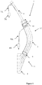
- FIG. 1 shows a cross-sectional view of an artificial airway assembly before insertion according to one embodiment 1 of the present invention.
- the integrated tubus and laryngeal mask device 1 comprises an outer laryngeal mask tube (OLT) 4 having proximal portion 12 and distal portion 11 .
- the OLT comprises a balloon cuff 5 in a communication with a longitudinal tube 3 .
- the balloon cuff 5 is shaped as a laryngeal mask, having at least one inflated configuration and at least one deflated configuration, and is in fluid connection with an inflating means.
- the balloon cuff is located at the distal end 11 of the OLT.
- the balloon cuff is an expansible member, made of an elastic material, which has an approximately toroidal shape.
- the integrated tubus and laryngeal mask device 1 further comprises a flexible airway tube (i.e., a tubus) 4 as an inner tube (tubus) located within the OLT 3.
- the tubus is characterized by a main longitudinal axis.
- the balloon cuff is connected to an inflation lumen 8A extending along the OLT and the tubus with an inflatable valve 8B , such as a pilot balloon, located at the inflation lumen edge.
- the valve assembly 8B is in fluid connection with the OLT and allows air to pass in and out of the OLT balloon cuff, allowing for easier insertion, as the OLT balloon cuff need not be inflated until it is already substantially in place.
- the OLT is adapted to conform to the space immediately adjacent to the larynx of the patient.
- the OLT is constructed of a resilient flexible biocompatible material in the form of a peripheral ring capable of defining a hollow space, capable of being inflated and deflated to accommodate the space adjacent to the larynx.
- the OLT adopts a configuration substantially conforming to the shape of the laryngeal inlet.
- the integrated tubus and laryngeal mask device 1 further comprises at least one lateral movement preventing element 9-10 located circumferentially to the tubus and between the inner lumen of the tubus and the OLT.
- the lateral movement preventing element is adapted to prevent lateral movement of the tubus with respect to the OLT such that a contact-free environment between the tubus and the OLT is provided.
- the lateral movement preventing element is further adapted to allow longitudinal reciprocating movement of the tubus along the main longitudinal axis with respect to the OLT.
- the main goal of the lateral movement preventing element is to create a peripheral sealing or a radial sealing of the inner volume between the tube of the OLT and the tubus, preventing any contamination of the inner tube or infection of the throat or esophagus.
- the lateral movement preventing element 9-10 is selected from the group consisting of: an O ring, an inflated balloon ring or any gasket which has the structure and character to create a peripheral seal or a radial seal in between the tubus and the OLT.
- the O-ring acts as a mechanical gasket. It has the shape of a torus, and is designed as a loop of elastomer with a disc-shaped cross-section.
- the lateral movement preventing element can be positioned in the distal portion or/and in the proximal portion of the device.
- the lateral movement preventing element can be activated by an inflation valve assembly 7 if inflation or deflation of the element is required.
- the integrated tubus and laryngeal mask device 1 further comprises a stopper 2 as an engagement part located in the proximal portion.
- the stopper fixedly secures the tubus to an operating position inside the OLT.
- the stopper prevents the tubus from traveling lengthwise in the OLT tube when ventilation is performed.
- the integrated tubus and laryngeal mask device 1 further comprises a guide wire substantially accommodated along the length of the OLT.
- the guide wire is adapted for immutability and easy intubation of the laryngeal mask by providing a stiffness characters to the OLT. Further more, the guide wire enables the laryngeal mask to be flexible and rigid simultaneously such that it will not collapse or fold when inserted to patient's delivery system.
- the guide wire is positioned within an inner canal of the laryngeal mask.
- the guide wire is further adapted for affixing and stabilizing the laryngeal mask within patient's throat. Further more, the OLT can be easily removed using the guide wire such that the OLT is peeled off from patient's throat whilst the tubus remains within the patient's throat.
- FIG. 2 shows a cross-sectional view of the integrated tubus and laryngeal mask device of a second embodiment of the invention.
- the tubus is inserted into patient's trachea until it is substantially in place order to intubate a patient.
- the tubus 4 is inserted into the mouth of the patient.
- the OLT 5 is positioned adjacent to the larynx, thus sealing at least partially the integrated tubus and laryngeal mask device for communication exclusively through the laryngeal inlet.
- air is injected into the OLT balloon cuff 5 via the valve assembly 8A-8B .
- the distal end of the fully inflatable cuff formation prevents the more rigid distal end of the OLT from catching the inside of the throat and subjecting the patient to undesirable forces.
- a valve assembly 7A-7B is presented.
- the valve assembly 7A-7B comprises an inflation lumen 7A and an operation valve 7B located within the edge of the inflation lumen.
- the valve assembly is in physical connection with the tubus.
- the valve 7A-7B controls the inflating and deflating activation respectively of a second balloon attached to the distal end of the tubus when the integrated tubus and laryngeal mask device is substantially in place. Air can be also injected into the second balloon 6 by use of a syringe, but any means known in the art may be used instead.
- FIG. 3 shows a cross-sectional view of the integrated tubus and laryngeal mask device of a third embodiment of the invention.
- the tubus is in its operating position as it is used to intubate a patient.
- the OLT balloon cuff 5 is positioned adjacent to the larynx, thus sealing at least partially the integrated tubus and laryngeal mask device for communication exclusively through the laryngeal inlet as it is positioned inside the trachea in order to start the ventilation process on a patient.
- the balloon cuff 5 is inflated to its first state so that it blocks entry into the esophagus of the TOLT.
- the balloon cuff 5 is deflated to its second state so that it provides no substantial obstruction within the mask 5.
- the tubus is fixedly secured inside the patient's trachea thus allowing deflation of the balloon cuff using the valve assembly 8A-8B .
- the resilience of the balloon 5 causes it to retract. Its thickness is reduced so that the balloon cuff lies flat against the surface of the OLT and adjacent to the OLT tube's walls, resulting an integration of the cuff with the tube of the OLT.
- the OLT tube is integrated with a deflated cuff balloon (masking ring) which provides a seal around the laryngeal inlet with an adjacent independent airway supply to the patient's lungs.
- FIG 3 further presents a second balloon 6 disposed about one side, which is inflated by supplying air or other fluid along the inflation lumen 7A in the usual way, so that the balloon expands to substantially fill the cavity of the trachea.
- the second balloon 6 is in physical contact with the tubus' distal end.
- the second balloon 6 may be of any appropriate biocompatible rubber-like material. In preferred embodiments of the invention, it is disposed on the outer circumference of the tubus. In other embodiments, it is disposed within tubus.
- an additional working tool may be inserted through the proximal portion of the OLT and into the trachea in a position from which a viewing device (e.g. a fiber optic device) can be used to observe the vocal cords.
- a viewing device e.g. a fiber optic device
- the artificial airway assembly defined above is provided with a pneumatic airway-directing mechanism which comprises at least one inflatable balloon useful to direct at least part of the integrated tubus and laryngeal mask device to a predetermined location.
- a pneumatic airway-directing mechanism which comprises at least one inflatable balloon useful to direct at least part of the integrated tubus and laryngeal mask device to a predetermined location.
- the integrated tubus and laryngeal mask device defined above is provided with a mechanical airway-directing mechanism which comprises at least one maneuverable effecter useful to direct at least part of the flexible airway to a predetermined location.
- the integrated tubus and laryngeal mask device which comprises an integrated mechanism, namely a pneumatic and mechanical mechanism, is possible.
- OLT outer laryngeal mask tube
- the balloon is in a fluid connection with an inflating means, located at the proximal end; and, (ii) an elongated tube in connection with the balloon cuff (TOLT); (b) an inner tube (tubus) located within the OLT; the tubus is characterized by a main longitudinal axis; and, (c) at least one lateral movement preventing element located circumferentially to the tubus and between the tubus and the OLT; adapted both (i) to prevent lateral movement of the tubus with respect to the OLT, such that contamination of the environment between the tubus and the OLT is prevented; and (ii) to allow longitudinal reciprocating movement of the tubus along the main longitudinal axis with respect to the OLT, in a manner that a seal is provided in the inner volume between the OLT and the tubus; wherein, when the balloon cuff is in the deflated configuration, the thickness of the same is reduced such that the balloon cuff is not protruding from the TOLT.
- Fig 4 illustrates a flow chart of a method for intubating a patient using a laryngeal mask assembly. It is a method for intubating a patient using an integrated tubus and laryngeal mask device, the method comprising a step of: (a) obtaining an integrated (I) tubus and (II) laryngeal mask device 100 , comprising: (i) an outer laryngeal mask tube (OLT) having proximal end and distal portion, comprising: (a) a laryngeal mask with integral balloon cuff, having at least one inflated configuration and at least one deflated configuration, located in the distal portion and in fluid connection with an inflating means located at the proximal end of the OLT; and, (b) a longitudinal tube in communication with the balloon cuff;
- OLT outer laryngeal mask tube
- the integrated tubus and laryngeal mask device further comprises an airway-directing mechanism disposed about one side of the tubus, the method further comprising a step of at least partially maneuvering the airway-directing mechanism whereby the tubus is directed toward the trachea of the patient.
- the OLT is further adapted for guiding the working tool to an operating position to view vocal cords and trachea of the patient.
- valve is a pilot balloon connected to an inflation lumen extending along the OLT and the tubus.
- the lateral movement preventing element is an O-ring.
- the O-ring has sizes specified by the outside diameter of the tubus and the cross sectional diameter between the tubus and the OLT.
- the O-ring is an elastomeric O-ring for sealing.
- lateral movement preventing element is ring-type balloon.
- the lateral movement preventing element is any type of a gasket which has the structure and characteristics to be placed between the tubus and the OLT.
- sealing structure is selected from the group consisting of: a peripheral seal, a radial seal, and any combination thereof.
- stopper has the size, shape and mechanism to reinforce the tubus.
- the balloon cuff is made of a flexible material.
- the first state is a state of the integrated tubus and laryngeal mask device which prevents entry of the esophagus into the internal cavity within the mask.
- the OLT tube has flexible walls integral with the cuff balloon of the OLT and substantially in contact with them when the cuff balloon is deflated.
- the second state is a state in which the internal cavity within the mask is substantially open.
- the second balloon and the balloon cuff are expansible members made of an elastic material.
- Fig 5 illustrates a flow chart of a method for producing a laryngeal mask assembly. It is provided a method of producing an integrated tubus and laryngeal mask device as defined above, comprising steps of: (a) providing an outer laryngeal mask tube (OLT) having proximal end and distal portion 200 having: (i) a balloon cuff shaped as a laryngeal mask, having at least one inflated configuration and at least one deflated configuration, located at the distal portion; the balloon in fluid connection with an inflating means, located at the proximal end, and an elongated tube in connection with the balloon cuff (TOLT); (ii) an inner tube (tubus); the tubus characterized by a main longitudinal axis; (iii) at least one lateral movement preventing element; (b) locating the tubus within the OLT 210 , (c) positioning the lateral movement preventing element circumferentially to the tubus and in between the tubus and the OLT
- the lateral movement preventing element is adapted both (i) to prevent lateral movement of the tubus with respect to the OLT, such that contamination of the environment between the tubus and the OLT is prevented; and (ii) to allow longitudinal reciprocating movement of the tubus along the main longitudinal axis with respect to the OLT, in a manner that a seal is provided for the inner volume between the OLT and the tubus.
- tubus additionally comprises a second inflatable balloon.
- seal is a peripheral seal.
- the inflating means is a pilot balloon valve connected to an inflation lumen extending along the OLT and the tubus.
- the second inflating means is a pilot balloon valve connected to an inflation lumen extending along the OLT and the tubus.
Landscapes
- Health & Medical Sciences (AREA)
- Pulmonology (AREA)
- Life Sciences & Earth Sciences (AREA)
- Public Health (AREA)
- Engineering & Computer Science (AREA)
- Biomedical Technology (AREA)
- Heart & Thoracic Surgery (AREA)
- Animal Behavior & Ethology (AREA)
- General Health & Medical Sciences (AREA)
- Veterinary Medicine (AREA)
- Anesthesiology (AREA)
- Hematology (AREA)
- Emergency Medicine (AREA)
- Surgery (AREA)
- Otolaryngology (AREA)
- Biophysics (AREA)
- Nuclear Medicine, Radiotherapy & Molecular Imaging (AREA)
- Molecular Biology (AREA)
- Medical Informatics (AREA)
- Pathology (AREA)
- Physics & Mathematics (AREA)
- Radiology & Medical Imaging (AREA)
- Optics & Photonics (AREA)
- Endoscopes (AREA)
- Prostheses (AREA)
Claims (16)
- Integrierte (i) Tubus und (ii) Kehlkopfmaskenvorrichtung (1), umfassend:a. eine äußere Larynxmaskenröhre (OLT) (3) mit einem proximalen Abschnitt (12) und einem distalen Abschnitt (11); bestehend aus:i. einer Ballonmanschette (5), die als Kehlkopfmaske geformt ist und mindestens eine aufgeblasene Konfiguration und mindestens eine entleerte Konfiguration aufweist, die in dem distalen Abschnitt (11) angeordnet ist; der Ballon in einer Fluidverbindung mit einer Aufblaseinrichtung (8A, 8B), die an dem proximalen Ende angeordnet ist; und,ii. einer länglichen Röhre in Verbindung mit der Ballonmanschette (TOLT);b. eine innere Röhre (Tubus) (4), die innerhalb der OLT (3) angeordnet ist und eine Belüftung durch den Tubus ermöglicht; der Tubus (4) ist durch eine Hauptlängsachse gekennzeichnet; und,c. mindestens ein Element (9, 10) zur Verhinderung einer seitlichen Bewegung, das in Umfangsrichtung zu dem Tubus (4) und zwischen dem Tubus (4) und der OLT (3) angeordnet ist; adaptiert sowohl (i) um eine seitliche Bewegung des Tubus in Bezug auf die OLT zu verhindern, so dass eine Kontamination der Umgebung zwischen dem Tubus und der OLT verhindert wird; und (ii) um eine longitudinale Hin- und Her Bewegung des Tubus entlang der Hauptlängsachse in Bezug auf die OLT zu ermöglichen, in einer Weise, dass eine Abdichtung in dem inneren Volumen zwischen der OLT und dem Tubus vorgesehen ist wobei, wenn sich die Ballonmanschette (5) in der nicht aufgeblasenen Konfiguration befindet, die Dicke derselben verringert ist, so dass die Ballonmanschette (5) nicht von der TOLT vorsteht.
- Integrierte Tubus und Kehlkopfmaskenvorrichtung (1) nach Anspruch 1, zusätzlich umfassend ein Element ausgewählt aus einer Gruppe bestehend ausa. einem Stopper (2), der angepasst ist, um den Tubus (4) fest an der Betriebsposition innerhalb der OLT (3) zu befestigenb. einem Führungsdraht, der im Wesentlichen entlang der Länge der OLT untergebracht ist; der Führungsdraht befindet sich in einem Innenkanal der Larynxmaskewobei der Führungsdraht angepasst ist zum Befestigen und Stabilisieren der Kehlkopfmaske innerhalb des Rachens des Patienten.
- Integrierte Tubus und Kehlkopfmaskenvorrichtung (1) nach Anspruch 1, dadurch gekennzeichnet, dass eine der folgenden Aussagen eingehalten wirda. die OLT (3) kann unter Verwendung des Führungsdrahts leicht abgezogen werdenb. das Aufblasmittel (8A, 8B) ist ein Pilotballonventil, das mit einem Inflationslumen verbunden ist, das sich entlang der OLT (3) und des Tubus (4) erstreckt.c. das Seitenbewegungsverhinderungselement (9, 10) ist ein O-Ringd. das Seitenbewegungsverhinderungselement (9, 10) ist eine Dichtung, die die Struktur und die charakteristischen Elemente aufweist, die es ermöglichen, dass das Seitenbewegungsverhinderungselement zwischen dem Tubus und dem OLT platziert werden kanne. die Dichtungsstruktur ist ausgewählt aus der Gruppe bestehend aus: einer Umfangsdichtung, einer Radialdichtung und einer beliebigen Kombination davon.
- Integrierter Tubus und Kehlkopfmaskenvorrichtung (1) nach Anspruch 1, wobei das Seitenbewegungsverhinderungselement (9, 10) ein O-Ring ist.
- Integrierte Tubus- und Kehlkopfmaskenvorrichtung (1) nach Anspruch 4, wobei einer der folgenden Punkte erfüllt ista. die Größen des O-Rings sind durch den Außendurchmesser des Tubus (4) und den Querschnittsdurchmesser zwischen dem Tubus (4) und der OLT (3) festgelegtb. der O-Ring ist ein Elastomer O-Ring zum Abdichten.
- Integrierter Tubus und Kehlkopfmaskenvorrichtung (1) nach Anspruch 2, wobei der Stopper (2) die Bewegung des Tubus (4) in Längsrichtung in der OLT (3) verhindert.
- Integrierte Tubus und Kehlkopfmaskenvorrichtung (1) nach Anspruch 1, zusätzlich umfassend einen Manövriermechanismus, der angepasst ist, um das distale Ende des Tubus neu auszurichten.
- Integrierte Tubus und Kehlkopfmaskenvorrichtung nach einem der Ansprüche 1 bis 7, dadurch gekennzeichnet, dass einer der folgenden Punkte erfüllt ista. die OLT (3) ist ferner angepasst, um ein Arbeitswerkzeug zu einer Betriebsposition zu führen, um Stimmbänder und Luftröhre des Patienten zu betrachten;b. die OLT (3) führt ein Arbeitsgerät in einer Weise, die eine ununterbrochene Belüftung durch den Tubus ermöglicht.
- Integrierte Tubus und Kehlkopfmaskenvorrichtung (1) nach Anspruch 1, zusätzlich umfassend einen zweiten aufblasbaren Ballon (6), der am distalen Ende des Tubus (4) angeordnet ist.
- Integrierte Tubus und Kehlkopfmaskenvorrichtung (1) nach Anspruch 7, wobei eines der folgenden Gesichtspunkte erfüllt ista. wobei die integrierte Tubus und Kehlkopfmaskenvorrichtung (1) zusätzlich ein zweites Ventil (7A, 7B) zum Steuern des Aufblasens und Entleerens des zweiten Ballons (6) aufweist;b. der zweite Ballon (6) aus einem flexiblen Material hergestellt ist;c. der zweite Ballon (6) in physischem Kontakt mit einer Seite des Tubus (4) steht, wobei beim Aufblasen des zweiten Ballons (6), während die integrierte Tubus- und Kehlkopfmaskenvorrichtung (1) an Ort und Stelle ist, mindestens ein Teil des Tubus (4) ist in einer vorbestimmten Richtung positioniert; wobei der zweite Zustand ein Zustand ist, in dem der innere Hohlraum innerhalb der OLT im Wesentlichen offen ist;d. der zweite aufblasbare Ballon (6) außerhalb des flexiblen Luftwegs angeordnet ist;e. der zweite aufblasbare Ballon (6) innerhalb des flexiblen Luftwegs angeordnet ist;f. der zweite aufblasbare Ballon (6) ist in den flexiblen Luftweg integriert.
- Integrierter Tubus und Kehlkopfmaskenvorrichtung (1) nach Anspruch 1, wobei die Ballonmanschette (5) in ihren ersten Zustand aufgeblasen wird, wenn die Kehlkopfmaske eingeführt wird, so dass sie den Eintritt in die Speiseröhre der TOLT blockiert.
- Integrierte Tubus und Kehlkopfmaskenvorrichtung (1) nach Anspruch 10, wobei der erste Zustand ein Zustand des Tubus (4) ist, der den Eintritt des Ösophagus in den inneren Hohlraum innerhalb der OLT (3) verhindert.
- Integrierte Tubus und Kehlkopfmaskenvorrichtung (1) nach Anspruch 1, wobei der zweite aufblasbare Ballon (6) um eine Seite des Tubus (4) angeordnet ist und sich in physischem Kontakt mit diesem befindet.
- Integrierter Tubus und Kehlkopfmaskenvorrichtung (1) nach Anspruch 12, wobei die vorbestimmte Richtung in Richtung der Luftröhre des Patienten ist.
- Integrierte Tubus und Kehlkopfmaskenvorrichtung (1) nach Anspruch 1, dadurch gekennzeichnet, dass eine der folgenden Aussagen eingehalten wirda. die OLT (3) hat flexible Wände, die integral mit der Ballonmanschette (5) der OLT sind, und die beiden sind in Kontakt, wenn die Ballonmanschette entleert ist;b. die Ballonmanschette (5) ist ein dehnbares Element, das aus einem elastischen Material hergestellt ist;c. die Ballonmanschette (5) ist an der OLT (3) angebracht und kommuniziert mit einem Inflationslumen, das sich entlang der OLT und des Tubus erstreckt;d. die OLT (3) ist fest an der Betriebsposition des Tubus (4) befestigt.
- Integrierter Tubus und Kehlkopfmaskenvorrichtung (1) nach Anspruch 1, wobei die Ballonmanschette (5) in ihren zweiten Zustand entleert wird, sobald der Tubus (4) in die korrekte Position eingeführt ist, so dass er keine wesentliche Behinderung bereitstellt innerhalb der OLT (3).
Applications Claiming Priority (2)
| Application Number | Priority Date | Filing Date | Title |
|---|---|---|---|
| US201261719972P | 2012-10-30 | 2012-10-30 | |
| PCT/IL2013/050879 WO2014068558A1 (en) | 2012-10-30 | 2013-10-28 | An intumask assembly |
Publications (3)
| Publication Number | Publication Date |
|---|---|
| EP2914323A1 EP2914323A1 (de) | 2015-09-09 |
| EP2914323A4 EP2914323A4 (de) | 2016-06-22 |
| EP2914323B1 true EP2914323B1 (de) | 2018-12-12 |
Family
ID=50626580
Family Applications (1)
| Application Number | Title | Priority Date | Filing Date |
|---|---|---|---|
| EP13850523.5A Not-in-force EP2914323B1 (de) | 2012-10-30 | 2013-10-28 | Intumask-anordnung |
Country Status (3)
| Country | Link |
|---|---|
| US (1) | US20150283346A1 (de) |
| EP (1) | EP2914323B1 (de) |
| WO (1) | WO2014068558A1 (de) |
Families Citing this family (7)
| Publication number | Priority date | Publication date | Assignee | Title |
|---|---|---|---|---|
| US20150122251A1 (en) * | 2013-11-05 | 2015-05-07 | Arman Azhir | Kink resistant intubation device |
| WO2016187108A1 (en) * | 2015-05-15 | 2016-11-24 | The Cleveland Clinic Foundation | Reversible airway device and related method for ventilating a subject |
| US10596339B2 (en) | 2018-05-21 | 2020-03-24 | Sridhar R. Musuku | Intubation devices and methods of use |
| USD858752S1 (en) | 2018-05-21 | 2019-09-03 | Sridhar R. Musuku | Intubation device |
| CN109172983B (zh) * | 2018-08-03 | 2024-09-20 | 郑州大学第一附属医院 | 喉罩气管导管联合导管 |
| USD921185S1 (en) * | 2019-01-24 | 2021-06-01 | Sridhar R. Musuku | Intubation device |
| CN111905214B (zh) * | 2020-09-17 | 2025-04-11 | 安徽探索医疗器械科技有限公司 | 喉罩 |
Family Cites Families (27)
| Publication number | Priority date | Publication date | Assignee | Title |
|---|---|---|---|---|
| GB2111394B (en) * | 1981-12-16 | 1985-09-11 | Archibald Ian Jeremy Brain | Artificial airway device |
| US4681094A (en) * | 1985-11-27 | 1987-07-21 | American Medical And Emergency Research Corporation | Balloon laryngoscope |
| US5477851A (en) * | 1995-01-26 | 1995-12-26 | Callaghan; Eric B. | Laryngeal mask assembly and method for removing same |
| US6634354B2 (en) * | 1996-02-26 | 2003-10-21 | Evergreen Medical Incorporated | Laryngeal mask airway |
| GB2317830B (en) * | 1996-10-03 | 2000-03-29 | Smiths Industries Plc | Laryngeal mask airways and their manufacture |
| GB9705537D0 (en) * | 1997-03-18 | 1997-05-07 | Smiths Industries Plc | Laryngeal mask assemblies |
| GB9821771D0 (en) * | 1998-10-06 | 1998-12-02 | Brain Archibald Ian Jeremy | Improvements relating to laryngeal mask airway devices |
| US6631720B1 (en) * | 1999-10-07 | 2003-10-14 | Archibald I. J. Brain | Laryngeal mask with large-bore gastric drainage |
| GB0103815D0 (en) * | 2001-02-16 | 2001-04-04 | Smiths Group Plc | Laryngeal mask assemblies |
| US7159589B2 (en) * | 2001-08-23 | 2007-01-09 | Indian Ocean Medical Inc. | Disposable laryngeal mask airway device |
| US6705322B2 (en) * | 2002-03-11 | 2004-03-16 | Ti-Li Chang | Laryngeal mask airway |
| GB0218868D0 (en) * | 2002-08-14 | 2002-09-25 | Nasir Muhammed A | Improved airway management device |
| US7128071B2 (en) * | 2003-09-10 | 2006-10-31 | Indian Ocean Medical Inc. | Intubating laryngeal mask airway device with fiber optic assembly |
| US20070028923A1 (en) * | 2005-08-08 | 2007-02-08 | Patrick Souris | Tip-laryngeal airway |
| US8225794B2 (en) * | 2006-01-13 | 2012-07-24 | Olympus Medical Systems Corp. | Overtube |
| DE102006029182B3 (de) * | 2006-06-24 | 2007-07-12 | Universitätsklinikum Schleswig-Holstein | Larynxmaske mit integriertem Endotrachealtubus |
| GB0700388D0 (en) * | 2007-01-10 | 2007-02-14 | Smiths Group Plc | Laryngeal mask assemblies and obturators |
| US20080257356A1 (en) * | 2007-04-23 | 2008-10-23 | The Penn State Research Foundation | Control tip for supraglottic airway device |
| FR2921840B1 (fr) * | 2007-10-08 | 2011-04-29 | Georges Boussignac | Dispositif d'assistance respiratoire |
| EP3329955B1 (de) * | 2009-02-06 | 2020-10-21 | Endoclear LLC | Gerät zur reinigung eines endotrachealtubus |
| US8468637B2 (en) * | 2009-02-06 | 2013-06-25 | Endoclear Llc | Mechanically-actuated endotracheal tube cleaning device |
| WO2011001437A2 (en) * | 2009-07-02 | 2011-01-06 | Tubular Medical Ltd. | Multi-layer endotracheal tube apparatus |
| DE102011001325B4 (de) * | 2011-03-16 | 2015-09-10 | Vbm Medizintechnik Gmbh | Larynxtubus und Verfahren zu dessen Herstellung |
| FR2973708B1 (fr) * | 2011-04-06 | 2013-05-10 | Georges Boussignac | Dispositif d'assistance respiratoire |
| US11135385B2 (en) * | 2012-01-10 | 2021-10-05 | Samreen Mehar Ali | Neonatal laryngeal mask airway |
| US20140041673A1 (en) * | 2012-08-13 | 2014-02-13 | Christopher C. Walters | Devices for containing fluid and debris on endotracheal tubes, laryngeal masks, endoscopes, bronchoscopes and catheters and method of use thereof |
| US10556077B2 (en) * | 2012-10-08 | 2020-02-11 | The Cleveland Clinic Foundation | Reversible airway device and related method for ventilating a subject |
-
2013
- 2013-10-28 EP EP13850523.5A patent/EP2914323B1/de not_active Not-in-force
- 2013-10-28 WO PCT/IL2013/050879 patent/WO2014068558A1/en not_active Ceased
- 2013-10-28 US US14/439,068 patent/US20150283346A1/en not_active Abandoned
Non-Patent Citations (1)
| Title |
|---|
| None * |
Also Published As
| Publication number | Publication date |
|---|---|
| EP2914323A4 (de) | 2016-06-22 |
| EP2914323A1 (de) | 2015-09-09 |
| WO2014068558A1 (en) | 2014-05-08 |
| US20150283346A1 (en) | 2015-10-08 |
Similar Documents
| Publication | Publication Date | Title |
|---|---|---|
| EP2914323B1 (de) | Intumask-anordnung | |
| EP2903673B1 (de) | Umkehrbare atemwegsvorrichtung | |
| EP1061983B1 (de) | Endotrachealtubus zum selektiven okkludierender bronchien | |
| US7938118B2 (en) | Combination laryngeal mask airway with dual blocking and fluid removal features and method | |
| US10786640B2 (en) | Reversible airway device and related method for ventilating a subject | |
| US20080066746A1 (en) | Method and device for placing an endotracheal tube | |
| JPH0359713B2 (de) | ||
| US20080011304A1 (en) | Endotracheal tube with suction attachment | |
| US20030192548A1 (en) | Laryngeal mask airway | |
| EP3458123B1 (de) | Dynamische katheterspitzenokklusion | |
| US20040000314A1 (en) | Airway assembly | |
| US20190201645A1 (en) | Laryngeal mask assembly | |
| US20150314094A1 (en) | Reversible airway device and related method for ventilating a subject | |
| US20170216545A1 (en) | Reversible airway device and related method for ventilating a subject | |
| CN113412134A (zh) | 用于维持患者中的气道的装置 | |
| CN114795363A (zh) | 联合气管导管的管壁附着式支气管封堵器 | |
| EP3880282B1 (de) | Trachealhilfe | |
| WO2017132423A1 (en) | Insertable device to prevent aspiration of stomach contents during ventilation and intubation | |
| EP3166672B1 (de) | Umkehrbare atemwegsvorrichtung | |
| EP3171924A1 (de) | Umkehrbare atemwegsvorrichtung und entsprechendes verfahren zur beatmung einer person | |
| CN221358064U (zh) | 气管插管组件 | |
| CA2100998C (en) | Laryngeal mask airway with concentric drainage of oesophagus discharge | |
| GB2542002A (en) | Tracheostomy tube assemblies |
Legal Events
| Date | Code | Title | Description |
|---|---|---|---|
| PUAI | Public reference made under article 153(3) epc to a published international application that has entered the european phase |
Free format text: ORIGINAL CODE: 0009012 |
|
| 17P | Request for examination filed |
Effective date: 20150520 |
|
| AK | Designated contracting states |
Kind code of ref document: A1 Designated state(s): AL AT BE BG CH CY CZ DE DK EE ES FI FR GB GR HR HU IE IS IT LI LT LU LV MC MK MT NL NO PL PT RO RS SE SI SK SM TR |
|
| AX | Request for extension of the european patent |
Extension state: BA ME |
|
| DAX | Request for extension of the european patent (deleted) | ||
| RA4 | Supplementary search report drawn up and despatched (corrected) |
Effective date: 20160520 |
|
| RIC1 | Information provided on ipc code assigned before grant |
Ipc: A61B 17/34 20060101ALI20160513BHEP Ipc: A61M 25/06 20060101ALI20160513BHEP Ipc: A61M 16/20 20060101ALI20160513BHEP Ipc: A61M 25/09 20060101ALI20160513BHEP Ipc: A61B 1/32 20060101ALI20160513BHEP Ipc: A61B 17/02 20060101ALI20160513BHEP Ipc: A61M 16/04 20060101AFI20160513BHEP |
|
| GRAP | Despatch of communication of intention to grant a patent |
Free format text: ORIGINAL CODE: EPIDOSNIGR1 |
|
| STAA | Information on the status of an ep patent application or granted ep patent |
Free format text: STATUS: GRANT OF PATENT IS INTENDED |
|
| RAP1 | Party data changed (applicant data changed or rights of an application transferred) |
Owner name: BRESLAUER LTD. |
|
| INTG | Intention to grant announced |
Effective date: 20180305 |
|
| GRAS | Grant fee paid |
Free format text: ORIGINAL CODE: EPIDOSNIGR3 |
|
| GRAA | (expected) grant |
Free format text: ORIGINAL CODE: 0009210 |
|
| STAA | Information on the status of an ep patent application or granted ep patent |
Free format text: STATUS: THE PATENT HAS BEEN GRANTED |
|
| AK | Designated contracting states |
Kind code of ref document: B1 Designated state(s): AL AT BE BG CH CY CZ DE DK EE ES FI FR GB GR HR HU IE IS IT LI LT LU LV MC MK MT NL NO PL PT RO RS SE SI SK SM TR |
|
| REG | Reference to a national code |
Ref country code: GB Ref legal event code: FG4D |
|
| REG | Reference to a national code |
Ref country code: CH Ref legal event code: EP |
|
| REG | Reference to a national code |
Ref country code: AT Ref legal event code: REF Ref document number: 1075152 Country of ref document: AT Kind code of ref document: T Effective date: 20181215 |
|
| REG | Reference to a national code |
Ref country code: DE Ref legal event code: R096 Ref document number: 602013048250 Country of ref document: DE |
|
| REG | Reference to a national code |
Ref country code: IE Ref legal event code: FG4D |
|
| REG | Reference to a national code |
Ref country code: NL Ref legal event code: MP Effective date: 20181212 |
|
| REG | Reference to a national code |
Ref country code: LT Ref legal event code: MG4D |
|
| PG25 | Lapsed in a contracting state [announced via postgrant information from national office to epo] |
Ref country code: ES Free format text: LAPSE BECAUSE OF FAILURE TO SUBMIT A TRANSLATION OF THE DESCRIPTION OR TO PAY THE FEE WITHIN THE PRESCRIBED TIME-LIMIT Effective date: 20181212 Ref country code: LV Free format text: LAPSE BECAUSE OF FAILURE TO SUBMIT A TRANSLATION OF THE DESCRIPTION OR TO PAY THE FEE WITHIN THE PRESCRIBED TIME-LIMIT Effective date: 20181212 Ref country code: FI Free format text: LAPSE BECAUSE OF FAILURE TO SUBMIT A TRANSLATION OF THE DESCRIPTION OR TO PAY THE FEE WITHIN THE PRESCRIBED TIME-LIMIT Effective date: 20181212 Ref country code: NO Free format text: LAPSE BECAUSE OF FAILURE TO SUBMIT A TRANSLATION OF THE DESCRIPTION OR TO PAY THE FEE WITHIN THE PRESCRIBED TIME-LIMIT Effective date: 20190312 Ref country code: HR Free format text: LAPSE BECAUSE OF FAILURE TO SUBMIT A TRANSLATION OF THE DESCRIPTION OR TO PAY THE FEE WITHIN THE PRESCRIBED TIME-LIMIT Effective date: 20181212 Ref country code: BG Free format text: LAPSE BECAUSE OF FAILURE TO SUBMIT A TRANSLATION OF THE DESCRIPTION OR TO PAY THE FEE WITHIN THE PRESCRIBED TIME-LIMIT Effective date: 20190312 Ref country code: LT Free format text: LAPSE BECAUSE OF FAILURE TO SUBMIT A TRANSLATION OF THE DESCRIPTION OR TO PAY THE FEE WITHIN THE PRESCRIBED TIME-LIMIT Effective date: 20181212 |
|
| REG | Reference to a national code |
Ref country code: AT Ref legal event code: MK05 Ref document number: 1075152 Country of ref document: AT Kind code of ref document: T Effective date: 20181212 |
|
| PG25 | Lapsed in a contracting state [announced via postgrant information from national office to epo] |
Ref country code: RS Free format text: LAPSE BECAUSE OF FAILURE TO SUBMIT A TRANSLATION OF THE DESCRIPTION OR TO PAY THE FEE WITHIN THE PRESCRIBED TIME-LIMIT Effective date: 20181212 Ref country code: SE Free format text: LAPSE BECAUSE OF FAILURE TO SUBMIT A TRANSLATION OF THE DESCRIPTION OR TO PAY THE FEE WITHIN THE PRESCRIBED TIME-LIMIT Effective date: 20181212 Ref country code: GR Free format text: LAPSE BECAUSE OF FAILURE TO SUBMIT A TRANSLATION OF THE DESCRIPTION OR TO PAY THE FEE WITHIN THE PRESCRIBED TIME-LIMIT Effective date: 20190313 Ref country code: AL Free format text: LAPSE BECAUSE OF FAILURE TO SUBMIT A TRANSLATION OF THE DESCRIPTION OR TO PAY THE FEE WITHIN THE PRESCRIBED TIME-LIMIT Effective date: 20181212 |
|
| PG25 | Lapsed in a contracting state [announced via postgrant information from national office to epo] |
Ref country code: NL Free format text: LAPSE BECAUSE OF FAILURE TO SUBMIT A TRANSLATION OF THE DESCRIPTION OR TO PAY THE FEE WITHIN THE PRESCRIBED TIME-LIMIT Effective date: 20181212 |
|
| PG25 | Lapsed in a contracting state [announced via postgrant information from national office to epo] |
Ref country code: PT Free format text: LAPSE BECAUSE OF FAILURE TO SUBMIT A TRANSLATION OF THE DESCRIPTION OR TO PAY THE FEE WITHIN THE PRESCRIBED TIME-LIMIT Effective date: 20190412 Ref country code: CZ Free format text: LAPSE BECAUSE OF FAILURE TO SUBMIT A TRANSLATION OF THE DESCRIPTION OR TO PAY THE FEE WITHIN THE PRESCRIBED TIME-LIMIT Effective date: 20181212 Ref country code: PL Free format text: LAPSE BECAUSE OF FAILURE TO SUBMIT A TRANSLATION OF THE DESCRIPTION OR TO PAY THE FEE WITHIN THE PRESCRIBED TIME-LIMIT Effective date: 20181212 Ref country code: IT Free format text: LAPSE BECAUSE OF FAILURE TO SUBMIT A TRANSLATION OF THE DESCRIPTION OR TO PAY THE FEE WITHIN THE PRESCRIBED TIME-LIMIT Effective date: 20181212 |
|
| PG25 | Lapsed in a contracting state [announced via postgrant information from national office to epo] |
Ref country code: RO Free format text: LAPSE BECAUSE OF FAILURE TO SUBMIT A TRANSLATION OF THE DESCRIPTION OR TO PAY THE FEE WITHIN THE PRESCRIBED TIME-LIMIT Effective date: 20181212 Ref country code: IS Free format text: LAPSE BECAUSE OF FAILURE TO SUBMIT A TRANSLATION OF THE DESCRIPTION OR TO PAY THE FEE WITHIN THE PRESCRIBED TIME-LIMIT Effective date: 20190412 Ref country code: SK Free format text: LAPSE BECAUSE OF FAILURE TO SUBMIT A TRANSLATION OF THE DESCRIPTION OR TO PAY THE FEE WITHIN THE PRESCRIBED TIME-LIMIT Effective date: 20181212 Ref country code: EE Free format text: LAPSE BECAUSE OF FAILURE TO SUBMIT A TRANSLATION OF THE DESCRIPTION OR TO PAY THE FEE WITHIN THE PRESCRIBED TIME-LIMIT Effective date: 20181212 Ref country code: SM Free format text: LAPSE BECAUSE OF FAILURE TO SUBMIT A TRANSLATION OF THE DESCRIPTION OR TO PAY THE FEE WITHIN THE PRESCRIBED TIME-LIMIT Effective date: 20181212 |
|
| REG | Reference to a national code |
Ref country code: DE Ref legal event code: R097 Ref document number: 602013048250 Country of ref document: DE |
|
| PLBE | No opposition filed within time limit |
Free format text: ORIGINAL CODE: 0009261 |
|
| STAA | Information on the status of an ep patent application or granted ep patent |
Free format text: STATUS: NO OPPOSITION FILED WITHIN TIME LIMIT |
|
| PG25 | Lapsed in a contracting state [announced via postgrant information from national office to epo] |
Ref country code: SI Free format text: LAPSE BECAUSE OF FAILURE TO SUBMIT A TRANSLATION OF THE DESCRIPTION OR TO PAY THE FEE WITHIN THE PRESCRIBED TIME-LIMIT Effective date: 20181212 Ref country code: DK Free format text: LAPSE BECAUSE OF FAILURE TO SUBMIT A TRANSLATION OF THE DESCRIPTION OR TO PAY THE FEE WITHIN THE PRESCRIBED TIME-LIMIT Effective date: 20181212 Ref country code: AT Free format text: LAPSE BECAUSE OF FAILURE TO SUBMIT A TRANSLATION OF THE DESCRIPTION OR TO PAY THE FEE WITHIN THE PRESCRIBED TIME-LIMIT Effective date: 20181212 |
|
| 26N | No opposition filed |
Effective date: 20190913 |
|
| PG25 | Lapsed in a contracting state [announced via postgrant information from national office to epo] |
Ref country code: TR Free format text: LAPSE BECAUSE OF FAILURE TO SUBMIT A TRANSLATION OF THE DESCRIPTION OR TO PAY THE FEE WITHIN THE PRESCRIBED TIME-LIMIT Effective date: 20181212 |
|
| PG25 | Lapsed in a contracting state [announced via postgrant information from national office to epo] |
Ref country code: MC Free format text: LAPSE BECAUSE OF FAILURE TO SUBMIT A TRANSLATION OF THE DESCRIPTION OR TO PAY THE FEE WITHIN THE PRESCRIBED TIME-LIMIT Effective date: 20181212 |
|
| REG | Reference to a national code |
Ref country code: CH Ref legal event code: PL |
|
| PG25 | Lapsed in a contracting state [announced via postgrant information from national office to epo] |
Ref country code: CH Free format text: LAPSE BECAUSE OF NON-PAYMENT OF DUE FEES Effective date: 20191031 Ref country code: LI Free format text: LAPSE BECAUSE OF NON-PAYMENT OF DUE FEES Effective date: 20191031 Ref country code: LU Free format text: LAPSE BECAUSE OF NON-PAYMENT OF DUE FEES Effective date: 20191028 |
|
| PGFP | Annual fee paid to national office [announced via postgrant information from national office to epo] |
Ref country code: FR Payment date: 20200427 Year of fee payment: 7 Ref country code: DE Payment date: 20200427 Year of fee payment: 7 |
|
| REG | Reference to a national code |
Ref country code: BE Ref legal event code: MM Effective date: 20191031 |
|
| PG25 | Lapsed in a contracting state [announced via postgrant information from national office to epo] |
Ref country code: BE Free format text: LAPSE BECAUSE OF NON-PAYMENT OF DUE FEES Effective date: 20191031 |
|
| PGFP | Annual fee paid to national office [announced via postgrant information from national office to epo] |
Ref country code: GB Payment date: 20200427 Year of fee payment: 7 |
|
| PG25 | Lapsed in a contracting state [announced via postgrant information from national office to epo] |
Ref country code: IE Free format text: LAPSE BECAUSE OF NON-PAYMENT OF DUE FEES Effective date: 20191028 |
|
| REG | Reference to a national code |
Ref country code: DE Ref legal event code: R119 Ref document number: 602013048250 Country of ref document: DE |
|
| PG25 | Lapsed in a contracting state [announced via postgrant information from national office to epo] |
Ref country code: CY Free format text: LAPSE BECAUSE OF FAILURE TO SUBMIT A TRANSLATION OF THE DESCRIPTION OR TO PAY THE FEE WITHIN THE PRESCRIBED TIME-LIMIT Effective date: 20181212 |
|
| GBPC | Gb: european patent ceased through non-payment of renewal fee |
Effective date: 20201028 |
|
| PG25 | Lapsed in a contracting state [announced via postgrant information from national office to epo] |
Ref country code: HU Free format text: LAPSE BECAUSE OF FAILURE TO SUBMIT A TRANSLATION OF THE DESCRIPTION OR TO PAY THE FEE WITHIN THE PRESCRIBED TIME-LIMIT; INVALID AB INITIO Effective date: 20131028 Ref country code: MT Free format text: LAPSE BECAUSE OF FAILURE TO SUBMIT A TRANSLATION OF THE DESCRIPTION OR TO PAY THE FEE WITHIN THE PRESCRIBED TIME-LIMIT Effective date: 20181212 Ref country code: DE Free format text: LAPSE BECAUSE OF NON-PAYMENT OF DUE FEES Effective date: 20210501 Ref country code: FR Free format text: LAPSE BECAUSE OF NON-PAYMENT OF DUE FEES Effective date: 20201031 |
|
| PG25 | Lapsed in a contracting state [announced via postgrant information from national office to epo] |
Ref country code: GB Free format text: LAPSE BECAUSE OF NON-PAYMENT OF DUE FEES Effective date: 20201028 |
|
| PG25 | Lapsed in a contracting state [announced via postgrant information from national office to epo] |
Ref country code: MK Free format text: LAPSE BECAUSE OF FAILURE TO SUBMIT A TRANSLATION OF THE DESCRIPTION OR TO PAY THE FEE WITHIN THE PRESCRIBED TIME-LIMIT Effective date: 20181212 |