EP2914458B1 - Dispositif servant à retenir des appareils plats sensiblement rectangulaires comme des tablettes électroniques ou des téléphones portables dans l'habitacle d'un véhicule à moteur - Google Patents
Dispositif servant à retenir des appareils plats sensiblement rectangulaires comme des tablettes électroniques ou des téléphones portables dans l'habitacle d'un véhicule à moteur Download PDFInfo
- Publication number
- EP2914458B1 EP2914458B1 EP13792287.8A EP13792287A EP2914458B1 EP 2914458 B1 EP2914458 B1 EP 2914458B1 EP 13792287 A EP13792287 A EP 13792287A EP 2914458 B1 EP2914458 B1 EP 2914458B1
- Authority
- EP
- European Patent Office
- Prior art keywords
- der
- slide
- holder
- carrier
- und
- Prior art date
- Legal status (The legal status is an assumption and is not a legal conclusion. Google has not performed a legal analysis and makes no representation as to the accuracy of the status listed.)
- Active
Links
Images












Classifications
-
- B—PERFORMING OPERATIONS; TRANSPORTING
- B60—VEHICLES IN GENERAL
- B60R—VEHICLES, VEHICLE FITTINGS, OR VEHICLE PARTS, NOT OTHERWISE PROVIDED FOR
- B60R11/00—Arrangements for holding or mounting articles, not otherwise provided for
- B60R11/02—Arrangements for holding or mounting articles, not otherwise provided for for radio sets, television sets, telephones, or the like; Arrangement of controls thereof
-
- B—PERFORMING OPERATIONS; TRANSPORTING
- B60—VEHICLES IN GENERAL
- B60R—VEHICLES, VEHICLE FITTINGS, OR VEHICLE PARTS, NOT OTHERWISE PROVIDED FOR
- B60R11/00—Arrangements for holding or mounting articles, not otherwise provided for
- B60R11/02—Arrangements for holding or mounting articles, not otherwise provided for for radio sets, television sets, telephones, or the like; Arrangement of controls thereof
- B60R11/0241—Arrangements for holding or mounting articles, not otherwise provided for for radio sets, television sets, telephones, or the like; Arrangement of controls thereof for telephones
-
- B—PERFORMING OPERATIONS; TRANSPORTING
- B60—VEHICLES IN GENERAL
- B60N—SEATS SPECIALLY ADAPTED FOR VEHICLES; VEHICLE PASSENGER ACCOMMODATION NOT OTHERWISE PROVIDED FOR
- B60N3/00—Arrangements or adaptations of other passenger fittings, not otherwise provided for
- B60N3/001—Arrangements or adaptations of other passenger fittings, not otherwise provided for of tables or trays
- B60N3/002—Arrangements or adaptations of other passenger fittings, not otherwise provided for of tables or trays of trays
-
- B—PERFORMING OPERATIONS; TRANSPORTING
- B60—VEHICLES IN GENERAL
- B60R—VEHICLES, VEHICLE FITTINGS, OR VEHICLE PARTS, NOT OTHERWISE PROVIDED FOR
- B60R11/00—Arrangements for holding or mounting articles, not otherwise provided for
- B60R11/02—Arrangements for holding or mounting articles, not otherwise provided for for radio sets, television sets, telephones, or the like; Arrangement of controls thereof
- B60R11/0252—Arrangements for holding or mounting articles, not otherwise provided for for radio sets, television sets, telephones, or the like; Arrangement of controls thereof for personal computers, e.g. laptops, notebooks
-
- F—MECHANICAL ENGINEERING; LIGHTING; HEATING; WEAPONS; BLASTING
- F16—ENGINEERING ELEMENTS AND UNITS; GENERAL MEASURES FOR PRODUCING AND MAINTAINING EFFECTIVE FUNCTIONING OF MACHINES OR INSTALLATIONS; THERMAL INSULATION IN GENERAL
- F16M—FRAMES, CASINGS OR BEDS OF ENGINES, MACHINES OR APPARATUS, NOT SPECIFIC TO ENGINES, MACHINES OR APPARATUS PROVIDED FOR ELSEWHERE; STANDS; SUPPORTS
- F16M11/00—Stands or trestles as supports for apparatus or articles placed thereon ; Stands for scientific apparatus such as gravitational force meters
- F16M11/02—Heads
- F16M11/04—Means for attachment of apparatus; Means allowing adjustment of the apparatus relatively to the stand
- F16M11/041—Allowing quick release of the apparatus
-
- F—MECHANICAL ENGINEERING; LIGHTING; HEATING; WEAPONS; BLASTING
- F16—ENGINEERING ELEMENTS AND UNITS; GENERAL MEASURES FOR PRODUCING AND MAINTAINING EFFECTIVE FUNCTIONING OF MACHINES OR INSTALLATIONS; THERMAL INSULATION IN GENERAL
- F16M—FRAMES, CASINGS OR BEDS OF ENGINES, MACHINES OR APPARATUS, NOT SPECIFIC TO ENGINES, MACHINES OR APPARATUS PROVIDED FOR ELSEWHERE; STANDS; SUPPORTS
- F16M11/00—Stands or trestles as supports for apparatus or articles placed thereon ; Stands for scientific apparatus such as gravitational force meters
- F16M11/02—Heads
- F16M11/04—Means for attachment of apparatus; Means allowing adjustment of the apparatus relatively to the stand
- F16M11/06—Means for attachment of apparatus; Means allowing adjustment of the apparatus relatively to the stand allowing pivoting
- F16M11/10—Means for attachment of apparatus; Means allowing adjustment of the apparatus relatively to the stand allowing pivoting around a horizontal axis
- F16M11/105—Means for attachment of apparatus; Means allowing adjustment of the apparatus relatively to the stand allowing pivoting around a horizontal axis the horizontal axis being the roll axis, e.g. for creating a landscape-portrait rotation
-
- F—MECHANICAL ENGINEERING; LIGHTING; HEATING; WEAPONS; BLASTING
- F16—ENGINEERING ELEMENTS AND UNITS; GENERAL MEASURES FOR PRODUCING AND MAINTAINING EFFECTIVE FUNCTIONING OF MACHINES OR INSTALLATIONS; THERMAL INSULATION IN GENERAL
- F16M—FRAMES, CASINGS OR BEDS OF ENGINES, MACHINES OR APPARATUS, NOT SPECIFIC TO ENGINES, MACHINES OR APPARATUS PROVIDED FOR ELSEWHERE; STANDS; SUPPORTS
- F16M11/00—Stands or trestles as supports for apparatus or articles placed thereon ; Stands for scientific apparatus such as gravitational force meters
- F16M11/20—Undercarriages with or without wheels
- F16M11/2007—Undercarriages with or without wheels comprising means allowing pivoting adjustment
- F16M11/2035—Undercarriages with or without wheels comprising means allowing pivoting adjustment in more than one direction
- F16M11/2064—Undercarriages with or without wheels comprising means allowing pivoting adjustment in more than one direction for tilting and panning
-
- F—MECHANICAL ENGINEERING; LIGHTING; HEATING; WEAPONS; BLASTING
- F16—ENGINEERING ELEMENTS AND UNITS; GENERAL MEASURES FOR PRODUCING AND MAINTAINING EFFECTIVE FUNCTIONING OF MACHINES OR INSTALLATIONS; THERMAL INSULATION IN GENERAL
- F16M—FRAMES, CASINGS OR BEDS OF ENGINES, MACHINES OR APPARATUS, NOT SPECIFIC TO ENGINES, MACHINES OR APPARATUS PROVIDED FOR ELSEWHERE; STANDS; SUPPORTS
- F16M13/00—Other supports for positioning apparatus or articles; Means for steadying hand-held apparatus or articles
- F16M13/02—Other supports for positioning apparatus or articles; Means for steadying hand-held apparatus or articles for supporting on, or attaching to, an object, e.g. tree, gate, window-frame, cycle
-
- B—PERFORMING OPERATIONS; TRANSPORTING
- B60—VEHICLES IN GENERAL
- B60R—VEHICLES, VEHICLE FITTINGS, OR VEHICLE PARTS, NOT OTHERWISE PROVIDED FOR
- B60R11/00—Arrangements for holding or mounting articles, not otherwise provided for
- B60R2011/0001—Arrangements for holding or mounting articles, not otherwise provided for characterised by position
- B60R2011/0003—Arrangements for holding or mounting articles, not otherwise provided for characterised by position inside the vehicle
-
- B—PERFORMING OPERATIONS; TRANSPORTING
- B60—VEHICLES IN GENERAL
- B60R—VEHICLES, VEHICLE FITTINGS, OR VEHICLE PARTS, NOT OTHERWISE PROVIDED FOR
- B60R11/00—Arrangements for holding or mounting articles, not otherwise provided for
- B60R2011/0001—Arrangements for holding or mounting articles, not otherwise provided for characterised by position
- B60R2011/0003—Arrangements for holding or mounting articles, not otherwise provided for characterised by position inside the vehicle
- B60R2011/0007—Mid-console
-
- B—PERFORMING OPERATIONS; TRANSPORTING
- B60—VEHICLES IN GENERAL
- B60R—VEHICLES, VEHICLE FITTINGS, OR VEHICLE PARTS, NOT OTHERWISE PROVIDED FOR
- B60R11/00—Arrangements for holding or mounting articles, not otherwise provided for
- B60R2011/0042—Arrangements for holding or mounting articles, not otherwise provided for characterised by mounting means
- B60R2011/0049—Arrangements for holding or mounting articles, not otherwise provided for characterised by mounting means for non integrated articles
- B60R2011/005—Connection with the vehicle part
- B60R2011/0061—Connection with the vehicle part using key-type connections
-
- B—PERFORMING OPERATIONS; TRANSPORTING
- B60—VEHICLES IN GENERAL
- B60R—VEHICLES, VEHICLE FITTINGS, OR VEHICLE PARTS, NOT OTHERWISE PROVIDED FOR
- B60R11/00—Arrangements for holding or mounting articles, not otherwise provided for
- B60R2011/0042—Arrangements for holding or mounting articles, not otherwise provided for characterised by mounting means
- B60R2011/0049—Arrangements for holding or mounting articles, not otherwise provided for characterised by mounting means for non integrated articles
- B60R2011/0078—Quick-disconnect two-parts mounting means
-
- B—PERFORMING OPERATIONS; TRANSPORTING
- B60—VEHICLES IN GENERAL
- B60R—VEHICLES, VEHICLE FITTINGS, OR VEHICLE PARTS, NOT OTHERWISE PROVIDED FOR
- B60R11/00—Arrangements for holding or mounting articles, not otherwise provided for
- B60R2011/0042—Arrangements for holding or mounting articles, not otherwise provided for characterised by mounting means
- B60R2011/008—Adjustable or movable supports
- B60R2011/0084—Adjustable or movable supports with adjustment by linear movement in their operational position
-
- B—PERFORMING OPERATIONS; TRANSPORTING
- B60—VEHICLES IN GENERAL
- B60R—VEHICLES, VEHICLE FITTINGS, OR VEHICLE PARTS, NOT OTHERWISE PROVIDED FOR
- B60R11/00—Arrangements for holding or mounting articles, not otherwise provided for
- B60R2011/0042—Arrangements for holding or mounting articles, not otherwise provided for characterised by mounting means
- B60R2011/008—Adjustable or movable supports
- B60R2011/0085—Adjustable or movable supports with adjustment by rotation in their operational position
-
- B—PERFORMING OPERATIONS; TRANSPORTING
- B60—VEHICLES IN GENERAL
- B60R—VEHICLES, VEHICLE FITTINGS, OR VEHICLE PARTS, NOT OTHERWISE PROVIDED FOR
- B60R11/00—Arrangements for holding or mounting articles, not otherwise provided for
- B60R2011/0042—Arrangements for holding or mounting articles, not otherwise provided for characterised by mounting means
- B60R2011/008—Adjustable or movable supports
- B60R2011/0085—Adjustable or movable supports with adjustment by rotation in their operational position
- B60R2011/0087—Adjustable or movable supports with adjustment by rotation in their operational position around two axes
-
- B—PERFORMING OPERATIONS; TRANSPORTING
- B60—VEHICLES IN GENERAL
- B60R—VEHICLES, VEHICLE FITTINGS, OR VEHICLE PARTS, NOT OTHERWISE PROVIDED FOR
- B60R11/00—Arrangements for holding or mounting articles, not otherwise provided for
- B60R2011/0042—Arrangements for holding or mounting articles, not otherwise provided for characterised by mounting means
- B60R2011/008—Adjustable or movable supports
- B60R2011/0085—Adjustable or movable supports with adjustment by rotation in their operational position
- B60R2011/0089—Adjustable or movable supports with adjustment by rotation in their operational position around three axes, i.e. universally mounted
Definitions
- the invention relates to a holder for flat, roughly rectangular devices such as tablet computers or mobile phones, in particular a holder for a device for holding flat, roughly rectangular devices such as tablet computers or mobile phones in the interior of a motor vehicle, in particular for use by the driver or the passenger of the vehicle.
- a holder with the features of the preamble of claim 1 is from DE 10 2011 075 621 A1 known.
- Tablet computers and smartphones also make it possible to receive numerous information and entertainment programs that are of interest to the passenger.
- the tablet computers Since no folding tables are usually provided for the front seats of vehicles, the tablet computers must be placed on the front passenger seat or the center armrest for use by the driver.
- the front passenger seat is often occupied by a person or blocked with other objects and a flat space on the center console is usually only available to a very limited extent.
- For working on the tablet computer files are often also required, which makes handling the tablet computer even more difficult.
- Stands and holders for tablet computers and smartphones for use by the driver of vehicles are known, but they are often difficult to access or hinder or make impossible the use of the front passenger seat or the handling of vehicle controls or they cover displays and ventilation nozzles or endanger them the safety of vehicle occupants in the event of an accident.
- the object of the invention is to create a holder for flat, roughly rectangular devices such as tablet computers or cell phones, which can be adapted to different dimensions of the devices and ensures optimal protection against injuries to passengers in the event of an accident.
- the invention is preferably characterized by a fastening device for fastening the device to a vehicle component as well as a holder for receiving the devices and a transfer arrangement provided between the holder and the fastening device with which the holder can be moved into different positions relative to the vehicle component, the transfer arrangement being a on the fastening device arranged support element with a first swivel joint with an approximately vertically oriented axis of rotation and a pivot arm arranged near the upper end of the support element with a second swivel joint with an approximately horizontally oriented axis of rotation, which is connected to the holder.
- the transfer arrangement enables a very simple, robust and compact structure of the device with the possibility of the holder with the tablet computer in the smallest of spaces in any desired position of use in portrait or landscape format for convenient use by the driver and / or the passenger or in a Non-use position in which neither driver nor front passenger or the operation of the vehicle are impaired.
- the transfer arrangement preferably has a swivel arm on which is connected to the fastening device via a first rotary joint with an approximately vertically oriented axis of rotation and to the holder or the carrier via a second rotary joint with an approximately horizontally oriented axis of rotation.
- the transfer arrangement enables a very simple, robust and compact structure of the device with the possibility of the holder or the carrier with the tablet computer and / or the mobile phone in the smallest of spaces in any desired position of use in portrait or Landscape format for comfortable use by the driver and / or the front passenger or in a non-use position in which neither the driver nor the front passenger or the operation of the vehicle are impaired.
- the device is mounted in the vehicle in such a way that the axis of rotation of the first swivel joint runs approximately vertically and the swivel arm can preferably be rotated in an approximately horizontally oriented plane.
- the first swivel joint is preferably arranged at the lower end of the support element between the plug-in element and the support element and the second swivel joint at the end of the swivel arm between the swivel arm and the holder or the carrier.
- the holder has an approximately rectangular outer contour and the axis of rotation of the second swivel joint runs approximately parallel to two outer edges of the holder, the pivot arm being arranged near an outer edge of the holder and aligned parallel to this.
- the holder is connected to the pivot arm via a support arm, the longitudinal axis of the pivot arm and the longitudinal axis of the support arm being approximately perpendicular to one another.
- the support arm and the support element are preferably aligned parallel to one another and connected at right angles to the swivel arm at one end each.
- the holder is preferably connected to the support arm on its rear wall via a third hinge whose axis of rotation runs perpendicular to the broad side of the rear wall and can be rotated by at least 90 ° between a horizontal and a vertical position of use, the axis of rotation of the third hinge preferably being approximately at the intersection of the two Diagonals of the rear wall of the holder is arranged.
- a double joint is arranged between the pivot arm and the support arm with a pivot bearing which is connected to the pivot arm and a pivot bearing which is connected to the support arm, the pivot bearing rotating about an axis of rotation which is parallel to the axis of rotation of the first
- the rotary joint runs and the pivot bearing rotates about an axis of rotation which is perpendicular to the axis of rotation of the pivot bearing.
- manually releasable stops can be provided on the first swivel joint and / or on the second swivel joint and / or on the third swivel joint, which limit the angle of rotation of the support element or the swivel arm or the holder in predetermined positions.
- the receiving bush is preferably integrated as a built-in part in a cavity of a center console or arranged as an attachment on the outside of a center console.
- the receiving socket is arranged vertically aligned in the center console and the insertion opening for the plug element is arranged on the top of the center console, preferably near the side wall of the center console directed towards the passenger seat.
- the receiving socket can be arranged horizontally in the center console and the insertion opening for the plug-in element can be arranged on the side wall of the center console that is directed towards the passenger seat.
- the receiving socket is arranged horizontally or vertically aligned as a separate part on the outside of the side wall of the center console directed towards the passenger seat, the receiving socket with a screw or Adhesive connection can be attached to the top or to the side wall of the center console directed towards the passenger seat.
- the device is attached to a guide rail attached to the vehicle floor for one of the vehicle seats.
- a support is preferably attached to the front end in the direction of travel of the guide rail of the passenger seat arranged next to the center console, which protrudes approximately vertically upwards between the side wall of the center console directed towards the passenger seat and the side wall of the passenger seat directed towards the center console and at its upper end the first fastening means or the receiving socket is arranged.
- the support is preferably made in one piece from a stamped / bent part made of stable sheet metal and comprises a fastening element with a first segment that protrudes from the front into the guide rail or is arranged under the guide rail and a second segment that points from the guide rail towards the center console and a support element bent upwards at approximately right angles on the second segment, the broad sides of the two segments of the fastening element running approximately parallel to the vehicle floor and the broad side of the supporting element approximately parallel to the side wall of the center console.
- the receiving socket which is open at the top, is attached to the upper end of the support element.
- the first segment of the fastening element is screwed firmly to the vehicle floor together with the guide rail with the screw already present on the vehicle side for fastening the guide rail.
- the support element preferably rests on the side wall of the center console following the contour and is supported on the side wall of the center console with a rubber pad arranged at the upper end so that vibrations of the support and the devices attached to it are prevented.
- a screw can be provided with which the support element is level with the rubber pad can be screwed to the side wall of the center console.
- a double-sided adhesive tape with a foam intermediate layer or a detachable Velcro connection or a mechanical hooking between the support element and the center console could be provided.
- the support could also be attached directly to the vehicle floor or to the side wall of the passenger seat directed towards the center console in the same manner.
- the attachment or installation of the first fastening means or the receiving socket can take place between the center console and the driver's seat.
- the first fastening means or the receiving socket can be displaced parallel to the direction of travel and can be locked in different positions on a vehicle part, for example on the side wall of the center console or the side wall of a vehicle seat or on the vehicle floor or a guide rail for a vehicle seat.
- the holder or carrier In particular in the non-use position of the holder or carrier, which is parallel to the direction of travel and vertically aligned, it is advantageous if the holder or carrier can be moved parallel to the direction of travel, for example to the rear between the backrests of the driver and front passenger seats.
- the holder can be displaced, for example, via a horizontally arranged rail in which a slide with the device is guided.
- the first fastening means is preferably connected to the vehicle component via a ball joint, so that the axis of rotation of the first rotary joint can be aligned vertically independently of the contour of the vehicle component.
- the device can have a flat cuboid, preferably rectangular, carrier for comprise a plurality of holders that are rotated with the described fastening and transfer arrangements from a vertical non-use position between the driver and front passenger seats on the second swivel joint in a horizontal or inclined position of use and on the first swivel joint in any desired position towards the driver or front passenger can be swiveled.
- a flat cuboid, preferably rectangular, carrier for comprise a plurality of holders that are rotated with the described fastening and transfer arrangements from a vertical non-use position between the driver and front passenger seats on the second swivel joint in a horizontal or inclined position of use and on the first swivel joint in any desired position towards the driver or front passenger can be swiveled.
- the possibility of pivoting the carrier around the first pivot joint and tilting it around the second pivot joint is particularly advantageous for the use of tablet computers and mobile telephones, which can thus be aligned with the driver or front passenger or with people in the rear seats.
- the swivel arm is preferably attached centrally to one of the narrow side walls of the carrier, the axis of rotation of the second pivot joint preferably running parallel to the longitudinal edges of the carrier.
- the carrier can be rotated 360 ° about the second swivel joint and can preferably be locked in the two vertical non-use positions with a manually releasable latching device.
- a friction brake can be provided which fixes the carrier in the set positions by friction.
- a latching device can also be provided which also fixes the intermediate positions or only a friction brake without latching positions can be provided.
- the carrier can be used on both sides. This makes it possible to accommodate several holders for different devices or other objects that can be arranged on one and the other broad side of the carrier.
- one or the other broad side of the carrier can be turned upwards and into any inclined positions and pivoted about the first pivot bearing towards the driver or front passenger.
- the ability to pivot the carrier about the first pivot and tilt the second pivot is particularly useful for this use of tablet computers and mobile phones, which can be aligned steplessly to the driver or front passenger or people in the rear seats.
- objects or containers are formed on the two broad sides of the carrier of different receiving and storage trays for holders.
- One of the two broad sides of the carrier can also be designed as a table top, preferably with a circumferential edge.
- a receiving space with a receptacle for the swivel arm can be provided on the narrow side of the carrier directed towards the support element.
- the swivel arm could be extendable so that the distance between the carrier and the support element can be variably adjusted.
- cavities that are open to the outside or can be closed with a cover can be arranged in which, for example, fixed or fold-out cup holders are arranged that are accessible from one or the other broad side of the carrier.
- holders for holding flat, approximately rectangular devices such as tablet computers or mobile phones are arranged on one or both broad sides of the carrier.
- the holders comprise a receiving tray in which a holder for receiving the device is arranged.
- a receiving shell extending approximately over the width of the carrier is provided on a broad side of the carrier, in which a holder for a mobile phone is arranged.
- the receiving tray with a holder for a mobile phone is followed by a storage tray for storing smaller objects or for Insertion of a separate container, for example for food or waste, arranged on the carrier.
- the receiving tray for a holder of a mobile phone and the storage tray are preferably approximately the same width and are arranged together next to one another on a broad side of the carrier.
- a holder is provided on the other broad side of the carrier with a receiving shell extending approximately over the length and width of the carrier with a holder for a tablet computer.
- the user can either use the mobile phone and the storage tray or the tablet computer, depending on the position of the carrier.
- the holder for a mobile phone and the holder for a tablet computer can be arranged next to one another on a broad side of the carrier.
- the dimensions of the receiving trays are matched to the largest device to be accommodated in each case and the holders arranged in the receiving trays are designed in such a way that they can accommodate mobile telephones or tablet computers of different sizes.
- the brackets in a further preferred embodiment comprise two jaws movable relative to one another, the distance between which can be adjusted and locked to the respective width or length of a device inserted in the holder, for example with a spindle or a latching device so that the two jaws form fixed stops for a device inserted between the jaws.
- one of the jaws is designed as a U-shaped receiving pocket and the other jaw is provided with a movable retaining clip which is pretensioned with a spring in the direction of the inserted device and covers it so that it is securely held in the holder in all positions .
- the receiving pocket is formed on a side wall of the receiving shell.
- a lifting device is provided, which is preferably arranged on the holder and, after opening the retaining clip, lifts the device over the edge of the receiving shell to such an extent that it can be comfortably grasped and removed from the holder.
- the side walls of the receiving shells in which the brackets are arranged form stops for the devices inserted in the brackets so that they cannot slip laterally out of the brackets even at high accelerations such as can occur in an accident.
- the side edges of the receiving shells are so high that the upper edges of the devices inserted in the holder are covered so that no contact with the upper edges of the devices is possible in the event of an accident.
- the holders for cell phones and tablet computers are identical assemblies with identical components which can be inserted into the carrier.
- the carrier comprises two housing shells in which the receiving shells and the storage shell are formed and a carrier plate arranged between the two housing shells to which the housing shells are attached.
- a receptacle for the swivel arm and guides for parts of the holders are arranged on the support plate.
- One housing shell preferably comprises an outwardly open, approximately across the width of the carrier, receiving shell for a holder for a mobile phone and a laterally adjoining storage shell and the other housing shell preferably comprises an outwardly open, approximately along the length and the width of the carrier extending, receiving tray for a holder for a tablet computer.
- the housing shell provided for receiving tablet computers of different sizes is included a receiving tray and a holder arranged in the receiving tray so designed that it forms a holder provided with a flat rear wall which can be attached to a vehicle component directly or with a transfer arrangement of the embodiments described above.
- the rear wall of the holder is provided with a pivot bearing, so that the holder can be rotated between a portrait format position and a landscape format position.
- a device for wireless transmission - for example by induction - of current for charging devices fastened in the holders is provided on the carrier or holder.
- a container is provided with a receiving tray and a closable hinged lid for receiving in particular food or waste, which with centering and / or releasable holding means - for example clamps, magnets, snap hooks or the like - in the storage tray arranged on the carrier can be used and releasably attached.
- the hinged lid is secured to the receiving tray with a separate releasable lock so that the hinged lid can also be opened when the receiving tray is fixed to the carrier.
- the container attached to the carrier can also be opened and used, for example, as a waste container when the carrier is in the vertical non-use position.
- the terms “driver's seat” or “passenger seat” refer to left-hand drive vehicles in which the driver's seat is located on the left of the center console in the direction of travel and the passenger seat is on the right of the center console.
- Figs. 1 to 7 and Fig. 10 show a first embodiment of the device.
- the pivot arm 6 is tubular and aligned horizontally.
- the first swivel joint 7 is arranged, the axis of rotation z1 of which is oriented vertically.
- the plug element 3 On the underside of the swivel joint 7, the plug element 3 is arranged, which can be inserted vertically into the insertion opening 2a of a receiving socket 2 arranged in a vehicle component 15.
- the receptacle 2 is integrated in a cavity of the center console 15 and the insertion opening 2a is approximately aligned with the top 15b of the center console 15 ( FIGS. 3 to 7 )
- a release button 7c is attached to the top of the swivel joint 7, with which a form-fitting latching device for the swivel arm 6 on the swivel joint 7 can be released.
- the second swivel joint 8 is arranged, which is designed as a tubular extension of the swivel arm and whose axis of rotation x1 runs parallel to the longitudinal axis of the swivel arm 6.
- a plate-shaped support arm 10 is arranged on the second swivel joint 8 transversely to the pivot arm 6.
- the longitudinal axes of the swivel arm 6 and Support arm 10 are perpendicular to each other.
- the holder 5 for a tablet computer 1 is connected to the support arm 10 via the third swivel joint 11.
- the axis of rotation y of the third swivel joint is perpendicular to the rear wall 5a of the holder 5 and is arranged at the intersection of the diagonals of the rear wall 5a so that the holder 5 can be rotated 360 ° between locked portrait and landscape positions.
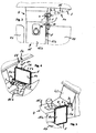
- the holder 5 can be moved with the first swivel joint 7 about a vertical axis Z1 from a storage position ( FIGS. 3 and 5 ) turn into different positions of use for the driver or front passenger ( Fig. 3, Fig. 4 , Fig. 7 ) and swivel with the second swivel joint 8 around a horizontal axis X1 ( Fig. 5 , Fig. 6, Fig. 7 ) and rotate with the third pivot bearing 11 between portrait and landscape format ( Fig. 5 ).
- a circumferential border 5b is provided on the edges of the rear wall 5a of the holder 5, which laterally support the tablet computer 1 inserted in the holder 5 and cover the edges of the screen 1a
- the tablet computer 1 is opened from the front ( Fig. 2 ) inserted in holder 5.
- the lower edge of the tablet computer 1 is inserted into the two receiving pockets 5c and the tablet computer 1 is pivoted into the holder 5 until the spring-loaded retaining clip 5d engages over the upper edge of the tablet computer 1.
- the retaining clip 5d is pressed outwards against the spring force parallel to the main side of the screen 1a.
- FIGS. 8 and 9 show two variants of receiving sockets 2 which are arranged on the side wall 15a of the center console 15 directed towards the front passenger seat 14.
- Fig. 8 shows a screwed to the side wall 15a of the center console 15
- Fig. 9 shows a receptacle 2 integrated in a cavity of the center console 15, its insertion opening 2a on the side wall 15a of FIG Center console 15 is arranged so that the plug element 3 can be inserted horizontally.
- the holder 5 and the plug-in element 3 can be rotated against each other around the second swivel joint 8 until the holder 5 and the plug-in element 3 lie above or next to each other ( Fig. 10 ).
- FIG. 11 to 13 show variants of the transfer arrangement.
- Fig. 11 a length-adjustable swivel arm 6.
- two tube sections 6 'and 6 are telescopically guided into one another and can be fixed in the desired extension length (not shown).
- Fig. 12 shows a plate-shaped pivot arm 6 on which, instead of the second swivel joint 8, a double joint 12 is provided, via which the support arm 10 is connected to the pivot arm 6.
- the double joint 12 comprises the pivot bearing 12a which is connected to the pivot arm 6 and the pivot bearing 12b which is connected to the support arm 10.
- the pivot bearing 12a rotates about the axis of rotation z2 which runs vertically parallel to the axis of rotation z1 of the first swivel joint 7 and the pivot bearing 12b rotates about the axis of rotation x2 which is perpendicular to the axis of rotation z2 of the rotary bearing 12a.
- Fig. 13 shows a height-adjustable support element 7d.
- a vertically aligned bearing pin 7a which, with a bearing sleeve 7b arranged at the end 6a of the pivot arm 6, forms the swivel joint 7.
- the bearing sleeve 7b can be fixed in the desired position on the bearing journal 7a by means of friction or a detachable latching device (not shown).
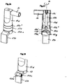
- Fig. 14 shows a locking device 9a, 9b, 9c with which the plug element 3 can be releasably locked in the receiving socket 2.
- a spring tongue 9c is provided on the plug element 3, which is provided with a latching hook 9a which snaps into a recess 9b made on the side wall of the receiving socket 2 when the Plug element is fully inserted into the receiving socket.
- the spring tongue 9c can be pressed towards the first swivel joint 7 until the latching hook 9a is released and the plug element 3 can be pulled out of the receptacle 2.
- the insertion opening 2a of the receiving socket 2 is closed with a hinged cover 2b so that the receiving socket 2 cannot get dirty.
- the hinged cover 2b is pivoted to the side in a cavity so that the plug-in element can be inserted into the receiving socket 2.
- FIGs. 15-25 show a second embodiment of the device.
- a vertically upwardly extending support element 17d is provided on the first swivel joint 17 arranged on the plug element 130, at the upper end of which the swivel arm 16 with the second swivel joint 18 is arranged at right angles.
- the support arm 110 is arranged on the second swivel joint 18, at the upper end of which the holder 150 is rotatably attached to the third swivel joint 111.
- the outer contour of the support element 17d is roughly aligned with the short side edge 150b 'of the Holder 150 and the outer contour of the swivel arm 16 with the second swivel joint 18 approximately with the long side edge 150b "of the holder 150 ( Fig. 24 ).
- Plug element 130 oriented approximately parallel to the side edges 150b 'and 150b "within the outer contours of the holder 150 ( Fig. 25 ).
- the height of the support element 17d is dimensioned such that the plane of rotation of the swivel arm 16 is so high that the holder 150 is positioned above both the legs of a passenger ( Fig. 21 ) as well as via the gear knob 15c ( Fig. 18 ) can be swiveled towards the driver.
- FIGs. 17-20 are various positions of use of the holder 150 for use by the driver and in the Figures 21 and 22 shown for use by the passenger.
- Figures 17, 19 and 21st show the holder 150 in landscape format.
- Figures 18, 20 and 22nd show the holder 150 in portrait format.
- Fig. 23 shows the holder 150 in a non-use position aligned parallel to the side wall 15a of the center console 15 in portrait format.
- Fig. 26 and Fig. 27 show an adjustment device for vertically aligning the axis of rotation z1 of the first swivel joint 17.
- the contours of the side walls 15a of the center consoles 15 on which the receptacle 120 is attached are often not vertical.
- a subsequently attached receiving socket 2, 120 is often mounted at an angle without the aid of a spirit level, so that the plane of rotation of the swivel arm 6, 16 does not run horizontally.
- a pivot bearing 17e is arranged at the lower end of the support element 17d, which is connected to the support element 17d via the pivot bearing 17e ′′ and forms the first pivot joint 7, 17.
- a spherical head cover 130a is attached which, together with the spherical socket 17e 'arranged on the lower side of the pivot bearing 17e, forms the ball joint 130a, 17e'.
- a spacer sleeve 17h is arranged in the center of the support element 17d which is supported on the pivot bearing 17e and is provided with internal threads at both ends.
- a pressure cap 17f is provided on the inside of the spherical head cover 130a, which is screwed into the lower thread of the spacer sleeve 17h with the clamping screw 17g and which prestresses the spherical head cover 130a against the ball socket 17e 'on the pivot bearing 17e.
- the support element 17d By loosening the clamping screw 17g, the support element 17d can be aligned vertically and fixed in this position by tightening the clamping screw 17g.
- the support element 17d is secured against axial displacement with the collar screw 17i, which is screwed into the upper thread of the spacer sleeve 17h, but remains rotatable together with the pivot arm 16.
- Fig. 28 shows a simplified variant of an adjusting device for vertically aligning the axis of rotation z1 of the first rotary joint 17 in an axis.
- the support element 17d can be aligned about an axis and fixed by tightening the locking screw 130b.
- the plug-in element 130 can be folded over and placed against the support element 17d.
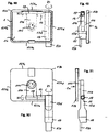
- Figures 29 to 31 show a further embodiment of the first and second fastening means 120, 130 with a locking device 19a, 19a ', 19a ", 19b.
- the first fastening means 120 comprises a base plate 120b, which is divided into the lamellae A to F by parallel V-shaped dilution channels ( FIGS. 30 and 31 ).
- the dilution channels have the function of film hinges, so that the base plate 120b also on curved surfaces, such as a side wall 15a of a center console 15 ( Fig. 8 ) can be attached by gluing or screwing. Screw holes 120b '''are provided on the outer slats A and F for screwing.
- two domes 120b are also on which the intermediate plate 120c, which comprises the receiving bushing 120, is fastened to the fastening arms 120c 'with the screws 120c".
- a free space is provided between the base plate 120b and the receptacle 120 ( Fig. 32 ) into which the base plate 120b can arch when attached to curved surfaces.
- the locking device 19a, 19a ', 19a ′′ is also arranged on the intermediate plate 120c a spring (not shown) is pretensioned so that the locking hook 19a snaps into the recess 19b on the plug-in element 130e and the plug-in element 130 is locked in the receiving socket 120 ( Fig. 31 ).
- the release button 19a 'down By pressing the release button 19a 'down, the lock is released and the plug element 130 can be pulled out of the receiving socket 120.
- a covering hood 120d is provided to cover the intermediate plate 120c.
- Fig. 33 shows a support element 17d at the lower end of which the first pivot bearing 17 is arranged.
- the plug-in element 130 is connected to the first pivot bearing 17 via the pivot joint 130b and can be fixed in the desired positions with the locking screw 130c.
- a horizontal position is shown in which the plug-in element is inserted into a horizontally aligned receiving socket 2, the insertion opening 2a of which is arranged on the outer wall 15a of a center console 15 ( Fig. 9 ).
- Fig. 34 shows a further variant of a receiving socket 2, which is arranged on the side wall 15a of a center console 15 and is fastened with the fastening arm 2e and the fastening screw 2d on the upper side 15b of the center console 15.
- FIGS. 35 to 37 show a further variant of a receiving socket 2 aligned vertically on the side wall 15a of a center console 15 an insertion opening 2a arranged at the top.
- Lateral fastening arms 2e ', 2e are attached to the narrow side walls of the receptacle bushing 2 and are provided with elongated holes 2f', 2f" for the blind rivet screws 2c, with which the receptacle bushing 2 is fastened to the side wall 15a with blind rivet nuts 2h ( Fig. 37 ).
- a recess 2g is provided so that the receptacle 2 can also be screwed tension-free to arched side walls 15a, for which purpose the elongated holes 2f ', 2f "are provided in which the screws 2c are slightly inclined can ask.
- FIG. 38 to 43 show a variant of the device that differs from that in the Figures 15 and 16
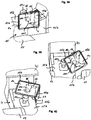
- the embodiment shown differs in that a stop cam 17l arranged on the first swivel joint 17 and a stop slot 17k arranged horizontally on the outer wall of the support element 17d in which the stop cam 17l rotates form stops that define the angle of rotation of the support element 17d and thus of the pivot arm 16 of the support arm 110 and the holder 150 to about 120 ° to 135 °, so that the holder 150 can only be rotated clockwise from the non-use position towards the center console 15 in about 120 ° to 135 ° ( Fig. 42 )
- a stop cam 18a is provided on the second swivel joint 18 and a stop recess 16c is provided on the swivel arm 16, which limit the swivel angle of the second swivel joint 18 and thus of the support arm 110 and the holder 150 to about 90 °, so that the holder 150 can be seen from a vertical position downward non-use position can be pivoted about 90 ° into a horizontal use position ( Fig. 42 ).
- the tablet computer 1 can be moved from the vertically downward non-use position ( Fig. 38 ) in inclined positions of use for both the front passenger ( Fig. 39 ) as well as the driver ( Fig. 40 ) can be aligned without removing the holder 150 to the extent to swivel into the passenger compartment that hindrances to the deployment of the passenger airbag could occur in certain vehicles.
- the holder 150 moves between the non-use position and the use positions for the driver and front passenger, essentially over the center console 15 so that the front passenger is also not obstructed.
- this arrangement enables the holder 150 to be adjusted very simply and quickly.
- Figures 44 to 47 show a further particularly compact and stable embodiment of the device.
- the pivot arm 160 is arranged at the upper end of the support element 170d and the second pivot bearing 180 is mounted in a fork-shaped manner on the pivot arm 160, the support element 170d and the support arm 110a being approximately in alignment.
- the rotation of the holder 150 about the first swivel joint 170 thus takes place on an arc of a circle with a smaller radius, which can be advantageous in tight spaces in the vehicle.
- Figures 44 and 45 show the device with the holder 150 and 150 pointing vertically downwards
- Figures 46 and 47 show the device with the holder 150 pointing vertically upwards.
- Figures 48 to 51 show the device as shown in FIG Figs. 38 to 43 with the arrangement of the support element 17d with the first swivel joint 17 and the plug-in element 130, the pivot arm 16 with the second swivel joint 18 and the support arm 110 with the third pivot bearing 111 in relation to the longitudinal edges 151a, 151c and the transverse edges 151b, 151d of the holder 150, with the holder in a vertically downward position ( 48 and 49 ) and vertically upward position ( Figures 50 and 51 ).
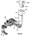
- Fig. 52 and 53 show an alternative fastening device with which the device can be fastened in a vehicle.
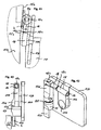
- the fastening device comprises a support 21, which is arranged approximately vertically between the center console and the vehicle seat (not shown), which at the lower end has a fastening element 21a at the front end of a guide rail 14c arranged on the vehicle floor, in which the seat frame 14a of the vehicle seat with a slide 14b is slidably mounted, is releasably attached with a screw connection.
- the support 21 is made of sheet metal and is fastened at the lower end with a screw connection to the fastening element 21a, which engages under the guide rail 14c in a U-shape. At the upper end, the support 21 is bent in a U-shape. On the upper side, two tabs are notched out of the sheet metal which form the counter hooks 21b for the latching hooks 190a of the plug-in element 30.
- the receiving socket 20 is made of plastic and is fastened to the upper end of the support 21 with a screw connection (not shown).
- the support 21 is covered with a cover panel 21c.
- the plug element 20 can be inserted into the receiving socket 20 from above until the latching hooks 190a engage in the counter-hooks 21b. The locking is released by pressing the release buttons 190a ′ on the plug element 30.
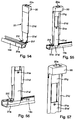
- Figs. 54 to 58 show a further variant of the fastening device.
- the support 21 comprises a profile rail 21d with a C-shaped cross section and a broad side curved in the transverse direction, so that a high level of stability of the support is achieved and damage to the upholstery of the vehicle seat when the seat is moved is prevented.
- the profile rail is open at both ends so that the locking plate 21g with the two notched counter hooks 21b can be inserted into the rail and pressed into the rail at the upper end.
- the fastening element 21a is designed as a C-shaped sheet metal part and surrounds the guide rail 14c from below. For assembly, the fastening element 21a can be pushed onto the free-standing end of the guide rail 14c from the front.
- the fastening element is on the side facing the center console15
- the foot 21a ′′ projects beyond the platform of the fastening element 21a and presses on the upper side of the guide rail 14c so that the fastening element 21a is clamped to the guide rail 14 when the clamping screws 21f are tightened.
- the guide rail 21a ' protrudes vertically upwards and can be inserted into the lower opening of the profile rail 21d.
- the profile rail 21d is guided linearly displaceably on the guide rail 21a ', so that the desired height of the receiving bushing can be set and fixed with the locking screw 21e.
- 59 to 68 show a further embodiment of the device with a plate-shaped rectangular carrier 300.
- the basic structure of the support element 270d with the first swivel joint 270 arranged at the lower end and the plug element 230 with the two latching hooks 290a and the two release buttons 290a 'as well as the pivot arm 260 arranged at the upper end correspond to the previously described concepts to which reference is made.
- the axes of rotation of the first rotary joint 270 and of the second rotary joint 280 are perpendicular to one another.
- a carrier 300 is arranged on the pivot arm 260, the axis of rotation of the second swivel joint 280 running parallel to the longitudinal edges 300 ', 300' '' of the carrier 300 and centrally between them.
- a receiving space 310 is provided in which the pivot arm 260 is arranged in the center.
- the second pivot joint 280 can be arranged between the pivot arm 260 and the support element 270d or between the pivot arm 260 and the carrier 300 or within a two-part pivot arm 260.
- the carrier 300 can be rotated through 360 ° about the second swivel joint 280, with a latching device (not shown) being provided with which the carrier 300 is in the vertical non-use positions ( Fig. 61 ) and in the horizontal position of use ( Figs. 59 and 60 ) is blocked.
- a release button 300 e is provided for the lock.
- the cup holders comprise a cover 300c which can be folded out to the carrier 300 via a first joint 310c '90 ° and a support ring 300d which can be folded out to the cover 300c via a second joint 300d' 90 °, the axes of rotation of the first swivel joint 310c 'and of the second pivot joint 300d 'are aligned in parallel.
- the covers 300c and the support rings 300d lie parallel to the broad side of the carrier 300, folded up one above the other in the cavities of the receiving space 310 ( Fig. 62 ).
- the covers 300c are perpendicular to the broad side of the carrier 300 upwards and the support rings 300d are aligned parallel to the broad side of the carrier 300 and spaced from it ( Fig. 63 ).
- the carrier Adjacent to the receiving space 310, the carrier is shell-shaped and provided with a circumferential, outwardly inclined edge 300 ', 300 ", 300"', 300 "", the upper edges of which are flush with the closed covers 300c ( Fig. 59 ).
- retaining clips 300f ', 300f ′′ are arranged in the middle with which a container 400 with a receiving tray 400a and a lid 400b hinged to the receiving tray 400a with a film hinge can be releasably attached to the carrier 300 ( Figures 64 and 65 ).
- the outer contour of the receiving shell 400a is designed to be complementary to the shell-shaped inner shape of the carrier 300, 300 ', 300 ", 300"', 300 "", so that the container 400 is laterally supported when it is secured with the holding clips 300f ', 300f "on the Support 300 is attached.
- the cover 400b can be releasably locked to the receiving shell 400a with a locking clip 400c.
- the cover 400b On the narrow sides of the cover 400b are arranged centrally Recesses 400b ', 400b "are provided so that the retaining clips 300f', 300f" only hold the receptacle 400a on the carrier 300, but the lid 400b of the container 400 can be opened and locked separately to the receptacle 400a via the locking clip 400c.
- the retaining clips 300f ′, 300f ′′ can be moved outward until the container 400 can be removed from the carrier 300.
- FIG. 13 shows the device in the non-use position attached to the fastening element 21a at the front end of the guide rail 14c for the passenger seat 14, which is arranged near the center console 15, as in FIG Figures 52 to 58 shown and described.
- the carrier 300 can be rotated about the second swivel joint 280 by 90 ° into a horizontal use position and swiveled about the first swivel joint 270 180 ° against the driver's seat 13 or the front passenger seat 14.
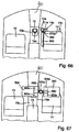
- Fig. 67 shows two positions of use of the carrier 300, above the center console 15 for use by the driver and above the passenger seat 14 for use by the passenger.
- the carrier 300 When not in use, the carrier 300 can be removed from the receiving socket 20 by releasing the latching hooks 290a with the release buttons 290a ' Fig. 53 ) separated and the support element 270d aligned and locked on the second swivel joint 280 parallel to the broad sides of the carrier 300 for space-saving storage ( Fig. 61 ).
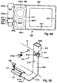
- Fig. 68 shows an alternative arrangement of the swivel arm 260 on the carrier 300. Instead of being arranged centrally between the two cup holders 300d, the swivel arm 260 is located near the outer edge 300 ′ in the receiving space 310. Otherwise, the embodiment corresponds to the illustrations in FIG 59 to 67 and is provided with identical reference numbers.
- Fig. 69 shows a further variant of the fastening device.
- the support 210 is made in one piece from a stamped / bent part made of stable sheet metal and comprises an L-shaped fastening element with the sections 210a, 210b and one at the end of the section 210b approximately Support section 210c bent upwards at right angles, the broad sides of sections 210a, 210b running approximately parallel to the vehicle floor and the broad side of support section 210c running approximately parallel to side wall 15a of center console 15.
- the receiving bushing 200 which is open at the top, is attached to the upper end of the support section 210c.
- section 210a is inserted from the front into C-shaped guide rail 14c of passenger seat 14 so that screw hole 210a 'on section 210a and screw hole 14c' on guide rail 14c are congruent on top of each other.
- the support 210 and the guide rail 14c are then screwed together firmly to the vehicle floor with the screw 14d already present on the vehicle side for fastening the guide rail 14c, without additional components being required.
- the support section 210c is biased with a slight bias against the side wall 15a of the center console 15 and is supported by the rubber pad 210d arranged at the upper end on the side wall 15a of the center console 15 so that vibrations of the support 210 and the devices 1, 300 can be prevented.
- a screw 210e is provided with which the support section 210c can be screwed to the side wall 15a of the center console 15 at the level of the rubber pad 210d.
- corresponding bores 210c ', 210d', 15a ' are provided on the support section 210c and on the rubber pad 210d and on the side wall 15a, which are congruent on top of one another when the support 210 has been inserted into the guide rail 14c and fastened with the screw 14d.
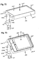
- Figures 70 and 71 show a hinged cover 200b for closing the insertion opening 20a, 200a of the receiving socket 20, 200 in the closed position.
- the hinged cover 200b is preferably articulated on the wide side wall 200c of the receiving socket 200 directed towards the front passenger seat 14 with a joint 200b 'with a horizontally oriented axis of rotation the leg spring 200b "is biased into the closed position, in which it covers the receiving socket 200.
- the hinged cover 200b is preferably provided with large safety radii all around on its outside.
- the hinged cover 200b When the plug-in element 30, 230 is inserted into the receiving socket 200, the hinged cover 200b is pressed with the leg spring 200b "against the broad side of the plug-in element 30, 230, the release buttons 190a ', 290a' for releasing the lock 190a, 290a ( Fig. 53 ) remain freely accessible.
- the spring-loaded hinged cover 200b automatically closes the insertion opening 20a, 200a of the receptacle 20, 200 so that it is protected from contamination.
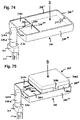
- the 72 to 77 show a further embodiment of the device with a carrier 300 which is arranged so that it can rotate 360 ° about the second swivel joint 280 and can be used on both sides.
- One broad side of the carrier (marked A) is designed as a table top and the other broad side of the carrier (marked B) is provided with two cup holders and a storage tray.
- side B corresponds in principle to the description of the representations in the Fig. 59 to Fig. 67 referred to. For this reason, the corresponding reference numerals are also used by the Fig. 59 to Fig. 67 used.
- Brackets 300f 'and 300f shown for holding the receiving tray 400a of the container 400 on the carrier 300 are shown in FIGS Fig. 74 , 78 and 79 Retaining lugs 311f ′, 311f ′′ attached to the carrier 300 which snap into correspondingly arranged retaining lugs (not shown) on the receiving shell 400a.
- the side A of the carrier 300 comprises a flat table top 311 which is provided with a non-slip covering and a circumferential edge 311 ', 311 ", 311' '', 311 '' '' which prevents objects such as tablet computers 1 or Mobile telephones 1 'can fall from the table top 311 with an inclined support 300 or lateral accelerations.
- the carrier 300 can be continuously rotated around the first rotary joint 270 in a horizontal plane and inclined continuously around the second rotary joint 280 so that, for example, the screen 1a of a tablet computer 1 or mobile phone 1 'attached to the carrier 300 can be continuously aligned with the user can.
- the carrier 300 can be attached to the second swivel joint 280 ( Figs. 59 to 65 ) rotate through 360 ° and can be locked in the two horizontal use positions and the two vertical non-use positions of the carrier 300 with a latching device (for example a spring-loaded spur toothing).
- the lock can be unlocked with the release button 300e.
- a friction brake is provided which fixes the carrier 300 in the intermediate positions by friction.
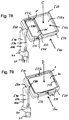
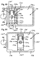
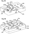
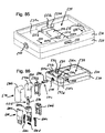
- 78 to 86 show a further embodiment of the device with a carrier 500 which is arranged on the end face 511a in the center of the swivel arm 560 and is rotatably mounted around the second swivel joint 580 360 ° and which has a first receiving tray 521 on a broad side (C) with a holder 540 located centrally in the first receiving tray 521 for a mobile phone 1 'as well as a storage tray 522 adjoining the first receiving tray 521 and on the other broad side (D) a second receiving tray 531 with a holder 550 for a tablet computer 1 arranged centrally in the second receiving tray 531.
- a carrier 500 which is arranged on the end face 511a in the center of the swivel arm 560 and is rotatably mounted around the second swivel joint 580 360 ° and which has a first receiving tray 521 on a broad side (C) with a holder 540 located centrally in the first receiving tray 521 for a
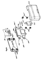
- the carrier 500 comprises a carrier plate 510 with a bottom wall 510a with two aligned parallel to the narrow side of the carrier 500 Slide guides 512a, 512b for the two slides 541, 551 of the two brackets 540, 550 and a bearing bushing 511 arranged in the middle of the end face 511a for receiving the swivel arm 560 and a first housing shell 520 and a second housing shell 530, which are positioned on the upper and lower respectively Be placed on the broad side of the carrier plate 510 and are provided with corresponding recesses for the two brackets 540, 550.
- the first housing shell 520 comprises the first receiving shell 521 for receiving the holder 540 for a mobile phone 1 ′ as well as the storage shell 522 and the second housing shell 530 comprises the second receiving shell 531 for receiving the holder 550 for a tablet computer 1.
- U-shaped receiving pockets 523, 532 are provided which the edge of the devices (mobile phone 1 'or tablet computer 1) on one side encompass.
- holders 540, 550 are provided in the receiving trays 521, 531, which include a slide 541, 551 with a stop plate (541d, 551d) which can be moved to different dimensions of the devices 1, 1 'can be adjusted and releasably fixed in the respective positions.
- a retaining clip 545, 555 with a hold-down device 545c, 555c is movably arranged on the slide 541, 551 and is biased towards the device 1, 1 'with a spring 555d and is movable to the extent that the hold-down device 545c, 555c touches the edge of the device 1, 1 'covered.
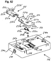
- the holder 540 for a mobile phone 1 ′ and the holder 550 for a tablet computer 1 are structurally identical using identical parts and are described below with reference to the illustrations of the holder 550 for a tablet computer 1 in FIG Fig. 82 described in detail.
- the holder 550 comprises a slide 551 with a base plate 551a and a stop plate 551d arranged at the end of the base plate 551a approximately perpendicular to the base plate 551a.
- Guide rails 551b are attached to the side edges of the base plate 551a and are guided in the slide guides 512b of the base wall 510a of the carrier plate 510a and with these form a linear guide for the slide 551.
- a locking element 553 On the underside of the base plate 551a there is a locking element 553 which is fastened to the base plate 551a with a screw via a spring arm 553a supported by a detent spring 553b.
- a recess 515b for the locking element 553 is provided on the bottom wall 510a so that the slide 551 can be moved unhindered.
- a release button 553d protruding through a button recess 551c in the base plate 551a is attached with toothed segments 553c arranged on both sides, which are held with the detent spring 553b in engagement with two toothed rails 514 arranged on the underside of the base wall 510a and the slide 551 hold in the desired positions.
- the release button 553d To move the slide 551, the release button 553d must be pressed, whereby the toothed segment 553c is released from the toothed rails 514.
- the toothed segments 553c and the toothed rails 514 are provided with sawtooth-shaped serrations which have the effect that the slide 551 can be pushed in the direction of a device 1 inserted into the holder 550 without pressing the release button 553d until the stop plate 551d touches the end wall of the device 1 while a Moving the slide 551 in the opposite direction is only possible after pressing the release button 553d.
- a retaining clip 555 is arranged on the slide 551 and has a base plate 555a which is mounted on the base plate 551a of the slide 551 so as to be longitudinally displaceable. At the free end of the base plate 555a there is arranged a stop wall 555b which is oriented approximately perpendicular to the base plate 555a and has a hold-down device 555c which is oriented approximately parallel to the base plate 555a and points towards the slide 551.
- a tension spring 555d is arranged between the slide 551 and the retaining clip 555, which pulls the retaining clip 555 against the slide 551 until the stop wall 555b of the retaining clip 555 rests against the stop plate 551d of the slide 551.
- a recess 555b ' is provided on the stop wall 555b in which the stop plate 551d of the slide 551 is received.
- the hold-down 555c protrudes beyond the stop plate 551d and covers the edge of a device 1 inserted into the holder 550 outside the screen 1a, so that the device 1 cannot fall out of the holder 550.
- the retaining clip 555 To remove the device 1 from the holder 550, the retaining clip 555 must be pulled outward against the force of the tension spring 555d until the device 1 is free and can be lifted out of the holder 550.
- a lifting device 552 is attached to the top of the base plate 551a, which lifts the device 1 after opening the retaining clip 555 so that it can be easily removed from the slide 551.
- Plug openings 513, 524, 533 are provided on the side walls of carrier plate 510 and housing shells 520, 530.
- the support element 590 and the swivel arm 560 form a common assembly with an L-shaped support part 590a and two symmetrical housing shells 590b. Between the carrier part 590a and the bearing bush 511 of the carrier 500, a cylindrical connecting piece 610a is inserted which comprises the second swivel joint 580 and a friction brake ( Fig. 86 ).
- the plug element 600 comprises a carrier part 600a in which the two Locking arms 600c supported and a compression spring which presses the locking arms 600c apart are housed, as well as two housing shells 600b. Between the support element 590 and the plug-in element 600, a cylindrical connecting piece 610b is inserted which comprises the first swivel joint 570 and a friction brake ( Fig. 86 ).
- Figs. 87 and 88 show a further embodiment of the device with the second housing shell 530 with a holder 550 arranged in the second receiving shell 531 for tablet computers 1 of different sizes, combined with a flat rear wall 535 provided with a swivel joint 535a, attached to a transfer arrangement (6, 7, 8, 10, 11, 16, 17, 18, 110, 111, 160, 170, 180, 560, 570, 580, 590) as shown in FIGS. 15 and 16 reference is made to their description.
Landscapes
- Engineering & Computer Science (AREA)
- General Engineering & Computer Science (AREA)
- Mechanical Engineering (AREA)
- Transportation (AREA)
- Vehicle Step Arrangements And Article Storage (AREA)
- Motor Or Generator Frames (AREA)
- Fittings On The Vehicle Exterior For Carrying Loads, And Devices For Holding Or Mounting Articles (AREA)
Claims (14)
- Support pour appareils plats essentiellement rectangulaires, tels que des tablettes électroniques (1) ou des téléphones portables (1'), comprenant une console (500) et une poche de réception (523, 532) en forme de U, reliée à la console (500) et qui enserre sur un côté le bord d'un appareil (1, 1') inséré dans le support, ainsi qu'une pince de retenue (545, 555) à ressort reliée de manière mobile à la console (500) et munie d'un presse-feuilles (545c, 555c) qui enserre sur le côté opposé le bord de l'appareil (1, 1') inséré dans le support, caractérisé en ce qu'une fixation (540, 550) est prévue, avec un coulisseau (541, 551) guidé de manière linéairement mobile au niveau de la console (500) et pouvant être bloqué dans différentes positions et une plaque de butée (541d, 551d) agencée au niveau du coulisseau (541, 551) et qui peut être mise en place par déplacement du coulisseau (541, 551) avec le bord opposé de l'appareil (1, 1') et peut être bloquée dans ladite position avec le coulisseau (541, 551), dans lequel la pince de retenue (545, 555) munie du presse-feuilles (545c, 555c) est agencée mobile au niveau du coulisseau (541, 551) et est précontrainte contre la plaque de butée (541d, 551d) par un ressort (555d).
- Support selon la revendication 1, dans lequel la console (500) comprend une paroi de fond (510a) au niveau de laquelle sont agencés des guides de coulisseau (512a, 512b) dans lesquels est guidé le coulisseau (541, 551).
- Support selon la revendication 2, dans lequel le coulisseau (541, 551) comprend une plaque de fond (541a, 551a) au niveau de laquelle sont agencés des rails de guidage (541b, 551b) avec lesquels le coulisseau (541, 551) est guidé dans les guides de coulisseau (512a, 512b) de la plaque de console (510).
- Support selon la revendication 3, dans lequel la plaque de butée (541d, 551d) est agencée au niveau de l'extrémité libre de la plaque de fond (541a, 551a) du coulisseau (541, 551) de manière essentiellement perpendiculaire à la plaque de fond (541a, 551a).
- Support selon l'une quelconque des revendications 1 à 4, dans lequel la pince de retenue (545, 555) comprend une plaque de fond (545a, 555a) qui est installée au niveau de la plaque de fond (541a, 551a) du coulisseau (541, 551) de manière à pouvoir être déplacée longitudinalement.
- Support selon la revendication 5, dans lequel une paroi de butée (545b, 555b) orientée de manière essentiellement perpendiculaire à la plaque de fond (545a, 555a) et munie d'un presse-feuilles (545c, 555c) orienté de manière essentiellement parallèle à la plaque de fond (545a, 555a) et tourné vers le coulisseau (541, 551) est agencée au niveau de l'extrémité libre de la plaque de fond (545a, 555a) de la pince de retenue (545, 555).
- Support selon la revendication 6, dans lequel un ressort (545d, 555d) est agencé entre le coulisseau (541, 551) et la pince de retenue (545, 555) et la pince de retenue (545, 555) se déplace contre le coulisseau (541, 551) jusqu'à ce que la paroi de butée (545b, 555b) de la pince de retenue (545, 555) arrive au niveau de la plaque de butée (541d, 551d) du coulisseau (541, 551).
- Support selon la revendication 6 ou 7, dans lequel un évidement (545b', 555b') accueillant la plaque de butée (541d, 551d) du coulisseau (541, 551) est prévu au niveau de la paroi de butée (545b, 555b) de la pince de retenue (545, 555).
- Support selon l'une quelconque des revendications 6 à 8, dans lequel le presse-feuilles (545c, 555c) fait saillie au-delà de la plaque de butée (541d, 551d) du coulisseau (541, 551) et recouvre le bord d'un appareil (1, 1') inséré dans la fixation (540, 550) de sorte que l'appareil (1, 1') ne puisse pas tomber de la fixation (540, 550).
- Support selon l'une quelconque des revendications 1 à 9, dans lequel un dispositif de verrouillage (514, 553) avec lequel le coulisseau (541, 551) peut être bloqué au niveau de la console (500) est agencé entre la console (500) et le coulisseau (541, 551).
- Support selon la revendication 10, dans lequel un bouton de libération (553d) permettant de relâcher le dispositif de verrouillage (514, 553) est prévu.
- Support selon la revendication 10 ou 11, dans lequel le dispositif de verrouillage (514, 553) comprend un rail denté (514) agencé au niveau de la console (500) et un segment denté (553c) agencé de manière mobile au niveau du coulisseau (541, 551) maintenu en prise avec le rail denté (514) par un ressort à cran d'arrêt (553b).
- Support selon la revendication 12, dans lequel le rail denté (514) et le segment denté (553c) sont munis de dentures en forme de dents de scie, de sorte que le coulisseau (541, 551) peut être poussé vers l'appareil (1, 1') inséré dans la fixation (540, 550) sans actionnement du bouton de libération (553d) tandis qu'un déplacement du coulisseau (541, 551) dans le sens opposé n'est possible qu'après actionnement du bouton de libération (553d).
- Support selon l'une quelconque des revendications 1 à 13, dans lequel une paroi arrière (535) plate munie d'un palier rotatif (535a) est prévue, de sorte que le support est rotatif entre une position portrait et une position paysage.
Applications Claiming Priority (10)
| Application Number | Priority Date | Filing Date | Title |
|---|---|---|---|
| CH22572012 | 2012-11-05 | ||
| CH26292012 | 2012-11-30 | ||
| CH2492013 | 2013-01-21 | ||
| CH9212013 | 2013-05-06 | ||
| CH9922013 | 2013-05-18 | ||
| CH10592013 | 2013-06-01 | ||
| CH12332013 | 2013-07-09 | ||
| CH13012013 | 2013-07-21 | ||
| CH17042013 | 2013-10-02 | ||
| PCT/EP2013/073080 WO2014068146A2 (fr) | 2012-11-05 | 2013-11-05 | Dispositif servant à retenir des appareils plats sensiblement rectangulaires comme des tablettes électroniques ou des téléphones portables dans l'habitacle d'un véhicule à moteur |
Publications (2)
| Publication Number | Publication Date |
|---|---|
| EP2914458A2 EP2914458A2 (fr) | 2015-09-09 |
| EP2914458B1 true EP2914458B1 (fr) | 2020-10-07 |
Family
ID=49596253
Family Applications (1)
| Application Number | Title | Priority Date | Filing Date |
|---|---|---|---|
| EP13792287.8A Active EP2914458B1 (fr) | 2012-11-05 | 2013-11-05 | Dispositif servant à retenir des appareils plats sensiblement rectangulaires comme des tablettes électroniques ou des téléphones portables dans l'habitacle d'un véhicule à moteur |
Country Status (5)
| Country | Link |
|---|---|
| US (1) | US9527456B2 (fr) |
| EP (1) | EP2914458B1 (fr) |
| CN (1) | CN104797461B (fr) |
| DE (1) | DE102013222449A1 (fr) |
| WO (1) | WO2014068146A2 (fr) |
Cited By (3)
| Publication number | Priority date | Publication date | Assignee | Title |
|---|---|---|---|---|
| US20220355744A1 (en) * | 2021-05-05 | 2022-11-10 | Kinetix Ag | Holder for detachably fastening a flat device to a motor vehicle seat |
| IT202200022650A1 (it) * | 2022-11-04 | 2024-05-04 | Ferrari Spa | Dispositivo di visualizzazione contenuti per veicolo stradale e relativo veicolo stradale |
| DE102023133537A1 (de) * | 2023-11-30 | 2025-06-05 | Bayerische Motoren Werke Aktiengesellschaft | Befestigungseinrichtung und Verfahren zum Befestigen des ersten Bauteils an einem zweiten Bauteil, insbesondere eines Kraftfahrzeugs, sowie Verwendung einer solchen Befestigungseinrichtung |
Families Citing this family (90)
| Publication number | Priority date | Publication date | Assignee | Title |
|---|---|---|---|---|
| US9933106B2 (en) * | 2013-03-14 | 2018-04-03 | Capsa Solutions, Llc | Height adjustable support |
| WO2015006388A2 (fr) * | 2013-07-09 | 2015-01-15 | Zodiac Seats Us Llc | Dispositif d'arrêt de frottement |
| TWM467100U (zh) * | 2013-08-15 | 2013-12-01 | Ming-Hsien Huang | 快拆裝置 |
| CA2927670C (fr) * | 2013-10-18 | 2017-02-21 | Ingenio Aerospace | Infrastructure pour dispositifs mobiles et equipement non fixe electronique |
| FR3012424B1 (fr) * | 2013-10-29 | 2017-05-19 | Etat Francais Represente Par Le Delegue General Pour L'armement | Support pour boitier anticollision et casquette pour planeur associee |
| DE102015215018A1 (de) | 2014-08-07 | 2016-02-11 | Kinetix Ag | Halter für flache in etwa rechteckige Geräte wie Tablet-Computer oder Smartphones |
| US9688207B1 (en) * | 2015-01-07 | 2017-06-27 | Thomas P. Pernici | Universally positional article mounting assemblies and methods |
| WO2016154731A1 (fr) * | 2015-04-02 | 2016-10-06 | Goupil Bernard | Support pour dispositif informatique de type tablette à écran tactile |
| DE102015210246A1 (de) * | 2015-06-03 | 2016-12-08 | Volkswagen Aktiengesellschaft | Gerätehalter für ein Fahrzeug |
| USD813857S1 (en) * | 2016-02-03 | 2018-03-27 | Kinetix Ag | Case for portable computers and mobile telephones |
| WO2017041914A1 (fr) * | 2015-09-09 | 2017-03-16 | Kinetix Ag | Support pour appareils plats approximativement rectangulaires tels qu'une tablette numérique ou un téléphone intelligent |
| CN106594476A (zh) * | 2015-10-19 | 2017-04-26 | 沈阳新松机器人自动化股份有限公司 | 屏幕支撑装置及具有该支撑装置的显示装置 |
| CN106809130B (zh) * | 2015-11-27 | 2019-06-25 | 比亚迪股份有限公司 | 用于车载多媒体元件的升降系统以及具有它的车辆 |
| EP3416854B1 (fr) * | 2016-02-15 | 2019-12-11 | Kinetix AG | Support pour appareils plats approximativement rectangulaires, tels que tablettes numériques ou téléphones intelligents |
| USD854537S1 (en) | 2016-02-16 | 2019-07-23 | Kinetix Ag | Vehicle mount |
| US10734773B2 (en) | 2016-04-18 | 2020-08-04 | Ingenio Aerospace Inc. | Infrastructure for mobile devices and electronic loose equipment |
| US9695972B1 (en) * | 2016-05-25 | 2017-07-04 | Panasonic Avionics Corporation | Quick-release mounting system for removably attaching a panel instrument to a structure |
| USD853224S1 (en) | 2016-06-01 | 2019-07-09 | Walmart Apollo, Llc | Wall mount fixture |
| US10281083B2 (en) * | 2016-06-01 | 2019-05-07 | Walmart Apollo, Llc | Mobile computing device holder |
| DE102016111448A1 (de) | 2016-06-22 | 2017-12-28 | Bury Sp.Z.O.O | Haltersystem für ein elektronisches Gerät in einem Fahrzeug |
| EP3266640B1 (fr) * | 2016-07-06 | 2019-06-19 | Volvo Car Corporation | Dispositif d'écran à mode multiple pour un véhicule et procédé permettant de fournir un dispositif à écran multimode dans un véhicule |
| US9968188B1 (en) * | 2016-07-11 | 2018-05-15 | Engineered Network Systems, Llc | Locking base for tablet stand |
| USD931291S1 (en) * | 2016-08-06 | 2021-09-21 | Rain Design, Inc. | Tablet computer stand |
| CN106122702A (zh) * | 2016-08-22 | 2016-11-16 | 苏州市华宁机械制造有限公司 | 一种平板显示器支架 |
| CN108082056B (zh) * | 2016-11-22 | 2020-04-24 | 比亚迪股份有限公司 | 车载电子装置和具有其的汽车 |
| CN108099608B (zh) * | 2016-11-24 | 2019-11-22 | 比亚迪股份有限公司 | 车载显示屏及出风组件和车辆 |
| US10434914B2 (en) * | 2017-03-13 | 2019-10-08 | Cnh Industrial America Llc | Armrest system for holding monitors in an operator cab |
| WO2018187070A1 (fr) * | 2017-04-04 | 2018-10-11 | Timco Aviation Services, Inc. | Système de siège comprenant un plateau escamotable |
| CN108700253B (zh) * | 2017-05-05 | 2019-12-20 | 杭州他若信息科技有限公司 | 用于全景的电动倾斜旋转设备和虚拟现实应用 |
| US10561249B2 (en) | 2017-05-23 | 2020-02-18 | Yeti Coolers, Llc | Portable chair and cup holder assembly |
| US10743670B2 (en) * | 2017-05-23 | 2020-08-18 | Yeti Coolers, Llc | Portable chair and cup holder assembly |
| US10619383B2 (en) | 2017-06-14 | 2020-04-14 | Walmart Apollo, Llc | Tether system |
| US10442537B2 (en) * | 2017-07-20 | 2019-10-15 | Johnny A. Satterfield | Deployable table assembly |
| CN109291857A (zh) * | 2017-07-25 | 2019-02-01 | 先锋高科技(上海)有限公司 | 车载显示屏装置 |
| GB2566012B (en) * | 2017-08-24 | 2020-05-06 | Ford Global Tech Llc | Vehicle furniture system |
| CN109501684B (zh) * | 2017-09-15 | 2022-01-07 | 比亚迪股份有限公司 | 用于车辆的显示屏组件和具有其的车辆 |
| USD890551S1 (en) * | 2017-09-26 | 2020-07-21 | Tesla, Inc. | Display bridge |
| FR3075715B1 (fr) * | 2017-12-22 | 2022-01-14 | Psa Automobiles Sa | Agencement d’un accouplement d’un support sur un dossier de siege de vehicule et siege de vehicule comprenant un tel accouplement |
| USD850810S1 (en) | 2018-01-10 | 2019-06-11 | Yeti Coolers, Llc | Portable chair |
| CN108248524A (zh) * | 2018-01-12 | 2018-07-06 | 深圳市麦思美汽车电子有限公司 | 一种能双轴方向旋转角度的机构 |
| CN108099808A (zh) * | 2018-01-19 | 2018-06-01 | 东莞市煜宸电子科技有限公司 | 车载设备支架 |
| DE102018201123A1 (de) * | 2018-01-24 | 2019-07-25 | Volkswagen Aktiengesellschaft | Anordnung zur Halterung eines mobilen Endgerätes sowie Fahrzeug mit einer derartigen Halterungsanordnung |
| CN108374951A (zh) * | 2018-02-09 | 2018-08-07 | 佛山市和富创电子科技有限公司 | 一种便携式电子设备支架装置 |
| WO2019161024A1 (fr) | 2018-02-14 | 2019-08-22 | Michael Shain | Appareil pour fixer des dispositifs électroniques à un appui-tête de véhicule |
| WO2020033737A1 (fr) * | 2018-08-08 | 2020-02-13 | Piironen Esa Kimmo | Commutateur de détection de proximité tactile capacitive dans un dispositif de balayage de code à barres |
| US11195347B2 (en) * | 2018-08-08 | 2021-12-07 | Motolink Llc | Operation and riding data collection device, and connectivity platform, for powersports vehicles |
| US20200062191A1 (en) * | 2018-08-27 | 2020-02-27 | Ragner Technology Corporation | Device holder systems for motor vehicles |
| DE102018218328B3 (de) * | 2018-10-26 | 2020-03-26 | Audi Ag | Anzeigevorrichtung für ein Kraftfahrzeug sowie Kraftfahrzeug mit einer derartigen Anzeigevorrichtung |
| US20200186181A1 (en) * | 2018-12-06 | 2020-06-11 | GM Global Technology Operations LLC | Wireless charging phone retention assembly |
| US10814746B2 (en) * | 2018-12-17 | 2020-10-27 | Honda Motor Co., Ltd. | Rotatable seat configuration with multi-use table |
| US11390221B1 (en) * | 2019-01-15 | 2022-07-19 | Joseph Michael Quicquaro | Pivotable vehicle tray |
| FR3093969B1 (fr) * | 2019-03-22 | 2021-05-14 | Faurecia Interieur Ind | Console centrale à dispositif d’affichage déplaçable et véhicule associé |
| US11345291B2 (en) * | 2019-03-26 | 2022-05-31 | Nissan North America, Inc. | Sliding tool assembly for a vehicle |
| DE102019003355A1 (de) * | 2019-05-13 | 2020-11-19 | Daimler Ag | Tischvorrichtung für ein Fahrzeug und Fahrzeug |
| DE102019209556A1 (de) * | 2019-06-28 | 2020-12-31 | Ford Global Technologies, Llc | Befestigungsvorrichtung für ein verstellbares Zubehörteil |
| CN110328518B (zh) * | 2019-07-15 | 2021-02-09 | 重庆惠科金扬科技有限公司 | 一种定位锁附治具 |
| CN112440888B (zh) * | 2019-08-30 | 2022-07-15 | 比亚迪股份有限公司 | 车辆的控制方法、控制装置及电子设备 |
| AU2020362546A1 (en) * | 2019-10-11 | 2022-04-14 | Staff Holdings Pty Ltd | A spirit level |
| US20220260204A1 (en) * | 2019-10-30 | 2022-08-18 | Fnss Savunma Sistemleri A.S. | Rotating mechanism with lockable gear |
| US11447010B2 (en) | 2019-12-04 | 2022-09-20 | Faurecia Automotive Seating, Llc | Passenger infotainment system |
| US11324314B2 (en) | 2020-02-21 | 2022-05-10 | Kohler Co. | Cabinet apparatus |
| FR3107484B1 (fr) * | 2020-02-26 | 2023-01-27 | Faurecia Interieur Ind | Station d’accueil pour véhicule |
| DE102020106031A1 (de) * | 2020-03-05 | 2021-09-09 | Zim Flugsitz Gmbh | Fluggastsitz und Sitzreihe |
| CN113685428A (zh) * | 2020-05-18 | 2021-11-23 | 索斯科锁定技术(深圳)有限公司 | 铰链装置 |
| CN111717124B (zh) * | 2020-06-05 | 2021-11-23 | 北京超星未来科技有限公司 | 一种可调节激光雷达角度的角度调节装置 |
| US11292397B2 (en) | 2020-07-30 | 2022-04-05 | Timothy White | Tablet holding assembly |
| KR102869257B1 (ko) * | 2020-10-06 | 2025-10-10 | 현대자동차주식회사 | 자동차용 시트백의 모니터 각도 자동 조절 장치 |
| DE202021104338U1 (de) * | 2021-08-13 | 2022-11-15 | Kinetix Ag | Befestigungssystem zur lösbaren Befestigung elektronischer Geräte in einem Kraftfahrzeug |
| EP4147908B1 (fr) * | 2021-09-08 | 2024-10-09 | Volvo Truck Corporation | Ensemble table pour camion |
| TWI762422B (zh) * | 2021-09-22 | 2022-04-21 | 緯創資通股份有限公司 | 電子裝置套組、其支架及其樞轉機構 |
| US20240416815A1 (en) * | 2021-10-29 | 2024-12-19 | Inteva Products, Llc | Console table |
| CN114110389A (zh) * | 2021-11-30 | 2022-03-01 | 安徽合力股份有限公司 | 一种叉车行驶操控特性测试装置 |
| CN114165695A (zh) * | 2021-12-16 | 2022-03-11 | 江苏长空测绘地理信息有限公司 | 一种便携式模块化测绘数据采集装置 |
| KR20230112944A (ko) * | 2022-01-21 | 2023-07-28 | 현대자동차주식회사 | 차량용 콘솔 |
| DE102022101821A1 (de) | 2022-01-26 | 2023-07-27 | Sevket Abidin Keskin | Vorrichtung zum Halten und/oder Laden eines mobilen Anzeigegerätes und Verwendung einer Vorrichtung von einem auf einer Liegestätte liegenden Betrachter |
| US20230371685A1 (en) * | 2022-05-23 | 2023-11-23 | Itc Incorporated | Rotating Tabletop for RV/Marine Having Tapered Gears |
| FR3139066A1 (fr) * | 2022-08-31 | 2024-03-01 | Safran Seats | Logement de charge à induction pour un siège muni d'un dispositif de retenue latéral |
| US11930920B1 (en) * | 2022-09-26 | 2024-03-19 | Whitecap Industries, Inc. | Side mount table leg assembly |
| US20240191466A1 (en) * | 2022-12-12 | 2024-06-13 | Great Plains Manufacturing, Inc. | Slide up cab door for work machine |
| CN219718283U (zh) * | 2023-02-07 | 2023-09-19 | 深圳市纽尔科技有限公司 | 一种手机夹 |
| CN118560400A (zh) * | 2023-02-28 | 2024-08-30 | 华为技术有限公司 | 用于固定负载的支架和车辆 |
| TWI829551B (zh) * | 2023-03-06 | 2024-01-11 | 明基電通股份有限公司 | 顯示器支架裝置 |
| DE202023101654U1 (de) * | 2023-03-31 | 2023-06-19 | Displine Gmbh | Wandhalterungssystem für ein Tablet |
| US20240388032A1 (en) * | 2023-05-16 | 2024-11-21 | Richard M. Beechler | Electronic port utility adapter |
| DE102023116804A1 (de) | 2023-06-27 | 2023-08-10 | Daimler Truck AG | Halterung für mobiles Endgerät im Lastkraftwagen |
| DE102023003477A1 (de) | 2023-08-24 | 2024-08-22 | Mercedes-Benz Group AG | Armauflage-Tisch-Anordnung für ein Fahrzeug |
| FR3154961A1 (fr) * | 2023-11-06 | 2025-05-09 | Stellantis Auto Sas | Bras mobile pour écran dans véhicule automobile |
| CN221340460U (zh) * | 2023-12-29 | 2024-07-16 | 深圳市玄碳科技有限公司 | 车载支架 |
| US20250282302A1 (en) * | 2024-03-08 | 2025-09-11 | Fisker Inc. | Rotatable vehicle display system powered by a motor having a flexible connection to the display system |
| DE102024004344B3 (de) | 2024-12-19 | 2026-03-05 | Mercedes-Benz Group AG | Haltevorrichtung zum Halten eines Bildschirms an einer Sitzanlage für einen Kraftwagen |
Citations (1)
| Publication number | Priority date | Publication date | Assignee | Title |
|---|---|---|---|---|
| DE102011075621A1 (de) * | 2010-05-10 | 2011-11-10 | Kinetix Ag | Vorrichtung zum Anbringen eines Tablet-Computers |
Family Cites Families (58)
| Publication number | Priority date | Publication date | Assignee | Title |
|---|---|---|---|---|
| US4165856A (en) * | 1977-06-15 | 1979-08-28 | Wiseheart Keith H | Adjustable artist's easel |
| US4455008A (en) * | 1980-12-22 | 1984-06-19 | Mackew James | Modular support system |
| US4836486A (en) * | 1987-04-16 | 1989-06-06 | Anthro Corporation | Adjustable support |
| US4946120A (en) * | 1988-08-09 | 1990-08-07 | Posting Equipment Corporation | Support |
| US5179447A (en) * | 1991-04-16 | 1993-01-12 | Hughes-Avicom International, Inc. | Personal video player and monitor assembly for airline passenger seat console |
| US5611513A (en) * | 1992-01-31 | 1997-03-18 | Rosen; John B. | Articulable projecting plug |
| US5485793A (en) * | 1993-02-08 | 1996-01-23 | Crowell; Anthony D. | Vehicle desk |
| US5769369A (en) * | 1995-04-28 | 1998-06-23 | Meinel; James | Mobile office stand for supporting a portable computer or electronic organizer in vehicles |
| US5555302A (en) * | 1995-07-18 | 1996-09-10 | Wang; Chin-Yang | Mobile telephone holder |
| US5673628A (en) * | 1995-12-12 | 1997-10-07 | Boos; Shane M. | Table for supporting and securing a portable computer in a vehicle |
| US5751548A (en) * | 1996-05-13 | 1998-05-12 | International Business Machines Corporation | Docking station for a portable computer providing rotational movement of the computer's viewable screen in three different planes |
| KR100303671B1 (ko) * | 1997-02-28 | 2001-09-24 | 포만 제프리 엘 | 휴대가능한컴퓨터용도킹스테이션및차량의컴퓨터조립체 |
| DE29708702U1 (de) | 1997-05-16 | 1997-07-17 | Herbert, Karl-Walter, 91091 Großenseebach | Einstellbare Halteeinrichtung für Bordcomputer in Kraftfahrzeugen, insbesondere für Laptop- oder Notebook-Computer |
| US5996954A (en) * | 1997-10-14 | 1999-12-07 | Rosen Products Llc | Stowable support apparatus |
| US6158793A (en) * | 1998-06-29 | 2000-12-12 | Castro; Jose | Concealable support for automotive accessory |
| DE19833888C1 (de) * | 1998-07-28 | 2000-01-27 | Fischer Artur Werke Gmbh | Klapptisch zur Anbringung an einer Rückseite einer Rückenlehne eines Fahrgastsitzes in einem Omnibus oder Flugzeug |
| US6386413B1 (en) * | 2000-03-27 | 2002-05-14 | Datalux Corporation | Apparatus and method for mounting a computer system in a vehicle |
| DE20010071U1 (de) * | 2000-06-05 | 2000-08-17 | Huang, Lin-Wei, Chung-Li, Taoyuan | Vorrichtung zur Halterung eines Mobiltelefons |
| DE10031314A1 (de) * | 2000-06-27 | 2002-01-17 | Ctech Ag Chur | Halterung zum Präsentieren mindestens eines länglichen Mehrzweck-Handgeräts |
| US20020066392A1 (en) * | 2000-12-01 | 2002-06-06 | Calam Henry D. | System, method, and support mechanism for supporting objects |
| US20020190171A1 (en) * | 2001-06-19 | 2002-12-19 | Stock Michael H. | Console bracket for supporting electronic apparatus |
| JP2003134209A (ja) * | 2001-10-26 | 2003-05-09 | Toshiba Corp | 無線機器ホルダ |
| US6585201B1 (en) * | 2002-03-08 | 2003-07-01 | Gregory Reed | Detachable universal display mount |
| DE10230643B4 (de) * | 2002-07-08 | 2006-05-11 | Johnson Controls Interiors Gmbh & Co. Kg | Tisch-Anordnung, insbesondere zum Einsatz in einem Kraftfahrzeug |
| US7121514B2 (en) * | 2003-08-22 | 2006-10-17 | Datalux Corporation | Best mode for carrying out the invention |
| US7040699B2 (en) * | 2003-12-11 | 2006-05-09 | Daimlerchrysler Corporation | Stowable seat mounted display screen |
| CN2691950Y (zh) * | 2004-02-02 | 2005-04-13 | 英华达股份有限公司 | 无线通讯装置的固定底座 |
| US7403613B2 (en) * | 2004-07-20 | 2008-07-22 | Haicom International Co., Ltd. | Holder for supporting objects in vehicle |
| WO2006078961A2 (fr) * | 2005-01-20 | 2006-07-27 | Mount Logic, Llc | Systemes de fixation articules et paliers destines a leurs articulations |
| US7261266B2 (en) * | 2005-03-31 | 2007-08-28 | Satterfield Johnny A | Deployable video arm |
| US20060290654A1 (en) * | 2005-06-06 | 2006-12-28 | Chin-Yang Wang | Holder for electronic apparatus |
| US7523528B2 (en) * | 2005-07-28 | 2009-04-28 | Carnevali Jeffrey D | Thumb release mounting apparatus |
| US7399033B2 (en) * | 2006-05-22 | 2008-07-15 | Rader Electronics Co., Ltd. | Vehicle video display device on armrest |
| US7537190B2 (en) * | 2006-06-13 | 2009-05-26 | Eagle Fan | Holding device for electronic apparatus |
| US9027486B1 (en) * | 2007-08-22 | 2015-05-12 | Arie Berkovitz | Portable collapsible writing desk for a notebook computer |
| US20090060473A1 (en) * | 2007-09-05 | 2009-03-05 | Kohte Hans H | Portable Video Media Device Holder |
| US7946542B1 (en) | 2007-11-28 | 2011-05-24 | Chapman Robert J | Adjustable laptop stand for vehicle |
| US20100038505A1 (en) * | 2008-08-18 | 2010-02-18 | Juliet Sonnenberg | Portable object support |
| US20100213335A1 (en) * | 2009-02-20 | 2010-08-26 | Chih-Ming Peng | Swivelable fixing seat |
| WO2010117758A2 (fr) * | 2009-03-30 | 2010-10-14 | Weber Aircraft Llc | Appareils de déploiement |
| US20110073743A1 (en) * | 2009-05-13 | 2011-03-31 | Steven Shamie | Universal holder and flexible member for mounting, holding and adjustably positioning electronic products and accessories |
| US20120126074A1 (en) * | 2009-07-27 | 2012-05-24 | Mark Garon | Device Support for a Stringed Instrument |
| US20110049321A1 (en) * | 2009-09-01 | 2011-03-03 | Wu Tieh-Han | Hanger Device |
| US20110121148A1 (en) * | 2009-11-24 | 2011-05-26 | Patrick Pernia | Apparatus and method for holding a portable electronic device |
| US8881659B2 (en) * | 2009-12-04 | 2014-11-11 | Kinetix Ag | Folding table for attachment to the rear side of a vehicle seat part |
| US8511629B2 (en) * | 2010-01-18 | 2013-08-20 | L&P Property Management Company | Mounting device |
| US9296340B2 (en) * | 2010-01-28 | 2016-03-29 | Kinetix Ag | Device for attaching a tablet computer |
| US9278648B2 (en) * | 2010-01-28 | 2016-03-08 | Kinetix Ag | Device for attaching a tablet computer |
| US8025015B1 (en) * | 2010-04-13 | 2011-09-27 | Kennedy Sr Mark B | Vehicle workstation |
| EP2563661B1 (fr) * | 2010-04-27 | 2014-12-10 | Panasonic Avionics Corporation | Système et procédé de déploiement pour dispositifs d'interfaces utilisateurs |
| US9045096B2 (en) * | 2010-05-14 | 2015-06-02 | Zodiac Seats Us Llc | Coupling assembly |
| US20120006870A1 (en) * | 2010-07-07 | 2012-01-12 | Jeff James Proctor | Support structure for electronic visual display device |
| CN103348174B (zh) * | 2011-02-10 | 2016-05-18 | Be航天股份有限公司 | 平板电脑支架和平板电脑装载系统 |
| US20130037590A1 (en) * | 2011-08-12 | 2013-02-14 | Namsung Co., Ltd. | Holder apparatus for mounting a media device in a vehicle |
| US20130083507A1 (en) * | 2011-09-29 | 2013-04-04 | Edward G. Guirlinger | Display Holder Assembly |
| DE202011106677U1 (de) * | 2011-10-12 | 2011-11-02 | Lisa Dräxlmaier GmbH | Haltevorrichtung für ein Fahrzeug |
| DE202011107952U1 (de) | 2011-11-16 | 2012-02-23 | Eagle Fan | Stützvorrichtung |
| US9103487B2 (en) * | 2012-03-24 | 2015-08-11 | Daymen Us, Inc. | Adjustable mounting clip and system using same |
-
2013
- 2013-11-05 US US14/437,501 patent/US9527456B2/en not_active Expired - Fee Related
- 2013-11-05 CN CN201380057841.XA patent/CN104797461B/zh not_active Expired - Fee Related
- 2013-11-05 WO PCT/EP2013/073080 patent/WO2014068146A2/fr not_active Ceased
- 2013-11-05 EP EP13792287.8A patent/EP2914458B1/fr active Active
- 2013-11-05 DE DE102013222449.4A patent/DE102013222449A1/de not_active Withdrawn
Patent Citations (1)
| Publication number | Priority date | Publication date | Assignee | Title |
|---|---|---|---|---|
| DE102011075621A1 (de) * | 2010-05-10 | 2011-11-10 | Kinetix Ag | Vorrichtung zum Anbringen eines Tablet-Computers |
Cited By (6)
| Publication number | Priority date | Publication date | Assignee | Title |
|---|---|---|---|---|
| US20220355744A1 (en) * | 2021-05-05 | 2022-11-10 | Kinetix Ag | Holder for detachably fastening a flat device to a motor vehicle seat |
| US11813989B2 (en) * | 2021-05-05 | 2023-11-14 | Kinetix Ag | Holder for detachably fastening a flat device to a motor vehicle seat |
| IT202200022650A1 (it) * | 2022-11-04 | 2024-05-04 | Ferrari Spa | Dispositivo di visualizzazione contenuti per veicolo stradale e relativo veicolo stradale |
| EP4364995A1 (fr) | 2022-11-04 | 2024-05-08 | FERRARI S.p.A. | Dispositif d'affichage de contenu pour véhicule routier et véhicule routier associé |
| US12496903B2 (en) | 2022-11-04 | 2025-12-16 | Ferrari S.P.A. | Content display device for road vehicle and relative road vehicle |
| DE102023133537A1 (de) * | 2023-11-30 | 2025-06-05 | Bayerische Motoren Werke Aktiengesellschaft | Befestigungseinrichtung und Verfahren zum Befestigen des ersten Bauteils an einem zweiten Bauteil, insbesondere eines Kraftfahrzeugs, sowie Verwendung einer solchen Befestigungseinrichtung |
Also Published As
| Publication number | Publication date |
|---|---|
| CN104797461B (zh) | 2017-07-25 |
| CN104797461A (zh) | 2015-07-22 |
| US9527456B2 (en) | 2016-12-27 |
| EP2914458A2 (fr) | 2015-09-09 |
| US20150329062A1 (en) | 2015-11-19 |
| DE102013222449A1 (de) | 2014-05-08 |
| WO2014068146A3 (fr) | 2014-09-12 |
| WO2014068146A8 (fr) | 2014-07-24 |
| WO2014068146A2 (fr) | 2014-05-08 |
Similar Documents
| Publication | Publication Date | Title |
|---|---|---|
| EP2914458B1 (fr) | Dispositif servant à retenir des appareils plats sensiblement rectangulaires comme des tablettes électroniques ou des téléphones portables dans l'habitacle d'un véhicule à moteur | |
| EP2507091B1 (fr) | Table repliable à placer sur l'arrière d'une partie de siège de véhicule | |
| EP3177487B1 (fr) | Support pour surface d'appareils approximativement rectangulaires tels les tablettes numériques ou les smartphones | |
| EP2528781B1 (fr) | Dispositif pour le montage d'un tablet-computer | |
| DE10234715B4 (de) | Drehbeweglicher Körper mit Entrastelement | |
| WO2012160209A1 (fr) | Équipement servant de support à une tablette électronique, en particulier dans un véhicule | |
| DE202008017895U1 (de) | Vorrichtung zum Anbringen eines Monitors | |
| WO2016166027A1 (fr) | Dispositif formant siège d'avion | |
| DE102013207930A1 (de) | Mittelarmlehne mit Tisch | |
| DE102017117343B4 (de) | Selbsteinrastende scharnierbaugruppe für schwingende tischfläche eines fahrzeugs | |
| DE102015117679A1 (de) | Konsolenarmlehne für ein Fahrzeug | |
| WO2004058536A1 (fr) | Cintre a appui-tete | |
| WO2006010500A1 (fr) | Systeme d'enfichage multifonctionnel | |
| DE102005030165B4 (de) | Befestigungsvorrichtung zum Haltern und/oder Sichern von Gegenständen | |
| EP2123245A1 (fr) | Fauteuil roulant, en particulier fauteuil roulant actif, doté d'un adaptateur de liaison | |
| DE9404515U1 (de) | Einstellbare Halteeinrichtung für Bordcomputer in Kraftfahrzeugen, insbesondere für Laptop- oder Notebook-Computer | |
| WO2008128586A1 (fr) | Support pour appareils mobiles | |
| DE10132039C2 (de) | Halterung für einen Laptop im Auto | |
| DE102008032326A1 (de) | Tischanlage für einen Innenraum eines Kraftfahrzeugs und Kraftfahrzeug mit einer Tischanlage | |
| DE102018003962B4 (de) | Innenraum eines Kraftfahrzeugs mit einem Klapptisch | |
| DE102020100358B4 (de) | Klappvorrichtung für ein Multifunktionsmöbel | |
| DE102014000026A1 (de) | Verstellbare Armlehne für ein Fahrzeug sowie Fahrzeug mit mindestens einer derartigen Armlehne | |
| DE202011101394U1 (de) | Lehnenanordnung für Rollstuhlfahrer zum Einbau in Kraftfahrzeugen | |
| DE102008053758B3 (de) | Vorrichtung zur Ablage von Gegenständen | |
| DE4445916C1 (de) | Klapptisch für Fahrzeuge |
Legal Events
| Date | Code | Title | Description |
|---|---|---|---|
| PUAI | Public reference made under article 153(3) epc to a published international application that has entered the european phase |
Free format text: ORIGINAL CODE: 0009012 |
|
| 17P | Request for examination filed |
Effective date: 20150420 |
|
| AK | Designated contracting states |
Kind code of ref document: A2 Designated state(s): AL AT BE BG CH CY CZ DE DK EE ES FI FR GB GR HR HU IE IS IT LI LT LU LV MC MK MT NL NO PL PT RO RS SE SI SK SM TR |
|
| AX | Request for extension of the european patent |
Extension state: BA ME |
|
| DAX | Request for extension of the european patent (deleted) | ||
| STAA | Information on the status of an ep patent application or granted ep patent |
Free format text: STATUS: EXAMINATION IS IN PROGRESS |
|
| 17Q | First examination report despatched |
Effective date: 20170718 |
|
| RAP1 | Party data changed (applicant data changed or rights of an application transferred) |
Owner name: KINETIX AG |
|
| STAA | Information on the status of an ep patent application or granted ep patent |
Free format text: STATUS: REQUEST FOR EXAMINATION WAS MADE |
|
| RIC1 | Information provided on ipc code assigned before grant |
Ipc: F16M 11/12 20060101ALI20200311BHEP Ipc: F16M 11/04 20060101ALI20200311BHEP Ipc: B60R 11/02 20060101AFI20200311BHEP |
|
| PUAG | Search results despatched under rule 164(2) epc together with communication from examining division |
Free format text: ORIGINAL CODE: 0009017 |
|
| GRAP | Despatch of communication of intention to grant a patent |
Free format text: ORIGINAL CODE: EPIDOSNIGR1 |
|
| STAA | Information on the status of an ep patent application or granted ep patent |
Free format text: STATUS: GRANT OF PATENT IS INTENDED |
|
| RIC1 | Information provided on ipc code assigned before grant |
Ipc: F16M 11/04 20060101ALI20200401BHEP Ipc: F16M 11/12 20060101ALI20200401BHEP Ipc: B60R 11/02 20060101AFI20200401BHEP |
|
| B565 | Issuance of search results under rule 164(2) epc |
Effective date: 20200428 |
|
| INTG | Intention to grant announced |
Effective date: 20200428 |
|
| RIC1 | Information provided on ipc code assigned before grant |
Ipc: B60R 11/02 20060101AFI20200420BHEP Ipc: F16M 11/12 20060101ALI20200420BHEP Ipc: F16M 11/04 20060101ALI20200420BHEP |
|
| GRAS | Grant fee paid |
Free format text: ORIGINAL CODE: EPIDOSNIGR3 |
|
| GRAA | (expected) grant |
Free format text: ORIGINAL CODE: 0009210 |
|
| STAA | Information on the status of an ep patent application or granted ep patent |
Free format text: STATUS: THE PATENT HAS BEEN GRANTED |
|
| AK | Designated contracting states |
Kind code of ref document: B1 Designated state(s): AL AT BE BG CH CY CZ DE DK EE ES FI FR GB GR HR HU IE IS IT LI LT LU LV MC MK MT NL NO PL PT RO RS SE SI SK SM TR |
|
| REG | Reference to a national code |
Ref country code: GB Ref legal event code: FG4D Free format text: NOT ENGLISH |
|
| REG | Reference to a national code |
Ref country code: CH Ref legal event code: EP Ref country code: AT Ref legal event code: REF Ref document number: 1320863 Country of ref document: AT Kind code of ref document: T Effective date: 20201015 |
|
| REG | Reference to a national code |
Ref country code: IE Ref legal event code: FG4D Free format text: LANGUAGE OF EP DOCUMENT: GERMAN |
|
| REG | Reference to a national code |
Ref country code: DE Ref legal event code: R096 Ref document number: 502013015196 Country of ref document: DE |
|
| REG | Reference to a national code |
Ref country code: NL Ref legal event code: MP Effective date: 20201007 |
|
| PG25 | Lapsed in a contracting state [announced via postgrant information from national office to epo] |
Ref country code: GR Free format text: LAPSE BECAUSE OF FAILURE TO SUBMIT A TRANSLATION OF THE DESCRIPTION OR TO PAY THE FEE WITHIN THE PRESCRIBED TIME-LIMIT Effective date: 20210108 Ref country code: RS Free format text: LAPSE BECAUSE OF FAILURE TO SUBMIT A TRANSLATION OF THE DESCRIPTION OR TO PAY THE FEE WITHIN THE PRESCRIBED TIME-LIMIT Effective date: 20201007 Ref country code: FI Free format text: LAPSE BECAUSE OF FAILURE TO SUBMIT A TRANSLATION OF THE DESCRIPTION OR TO PAY THE FEE WITHIN THE PRESCRIBED TIME-LIMIT Effective date: 20201007 Ref country code: PT Free format text: LAPSE BECAUSE OF FAILURE TO SUBMIT A TRANSLATION OF THE DESCRIPTION OR TO PAY THE FEE WITHIN THE PRESCRIBED TIME-LIMIT Effective date: 20210208 Ref country code: NL Free format text: LAPSE BECAUSE OF FAILURE TO SUBMIT A TRANSLATION OF THE DESCRIPTION OR TO PAY THE FEE WITHIN THE PRESCRIBED TIME-LIMIT Effective date: 20201007 Ref country code: NO Free format text: LAPSE BECAUSE OF FAILURE TO SUBMIT A TRANSLATION OF THE DESCRIPTION OR TO PAY THE FEE WITHIN THE PRESCRIBED TIME-LIMIT Effective date: 20210107 |
|
| REG | Reference to a national code |
Ref country code: LT Ref legal event code: MG4D |
|
| PG25 | Lapsed in a contracting state [announced via postgrant information from national office to epo] |
Ref country code: PL Free format text: LAPSE BECAUSE OF FAILURE TO SUBMIT A TRANSLATION OF THE DESCRIPTION OR TO PAY THE FEE WITHIN THE PRESCRIBED TIME-LIMIT Effective date: 20201007 Ref country code: SE Free format text: LAPSE BECAUSE OF FAILURE TO SUBMIT A TRANSLATION OF THE DESCRIPTION OR TO PAY THE FEE WITHIN THE PRESCRIBED TIME-LIMIT Effective date: 20201007 Ref country code: LV Free format text: LAPSE BECAUSE OF FAILURE TO SUBMIT A TRANSLATION OF THE DESCRIPTION OR TO PAY THE FEE WITHIN THE PRESCRIBED TIME-LIMIT Effective date: 20201007 Ref country code: IS Free format text: LAPSE BECAUSE OF FAILURE TO SUBMIT A TRANSLATION OF THE DESCRIPTION OR TO PAY THE FEE WITHIN THE PRESCRIBED TIME-LIMIT Effective date: 20210207 Ref country code: BG Free format text: LAPSE BECAUSE OF FAILURE TO SUBMIT A TRANSLATION OF THE DESCRIPTION OR TO PAY THE FEE WITHIN THE PRESCRIBED TIME-LIMIT Effective date: 20210107 Ref country code: ES Free format text: LAPSE BECAUSE OF FAILURE TO SUBMIT A TRANSLATION OF THE DESCRIPTION OR TO PAY THE FEE WITHIN THE PRESCRIBED TIME-LIMIT Effective date: 20201007 |
|
| PG25 | Lapsed in a contracting state [announced via postgrant information from national office to epo] |
Ref country code: HR Free format text: LAPSE BECAUSE OF FAILURE TO SUBMIT A TRANSLATION OF THE DESCRIPTION OR TO PAY THE FEE WITHIN THE PRESCRIBED TIME-LIMIT Effective date: 20201007 |
|
| REG | Reference to a national code |
Ref country code: CH Ref legal event code: PL |
|
| REG | Reference to a national code |
Ref country code: DE Ref legal event code: R097 Ref document number: 502013015196 Country of ref document: DE |
|
| PG25 | Lapsed in a contracting state [announced via postgrant information from national office to epo] |
Ref country code: SK Free format text: LAPSE BECAUSE OF FAILURE TO SUBMIT A TRANSLATION OF THE DESCRIPTION OR TO PAY THE FEE WITHIN THE PRESCRIBED TIME-LIMIT Effective date: 20201007 Ref country code: RO Free format text: LAPSE BECAUSE OF FAILURE TO SUBMIT A TRANSLATION OF THE DESCRIPTION OR TO PAY THE FEE WITHIN THE PRESCRIBED TIME-LIMIT Effective date: 20201007 Ref country code: LU Free format text: LAPSE BECAUSE OF NON-PAYMENT OF DUE FEES Effective date: 20201105 Ref country code: MC Free format text: LAPSE BECAUSE OF FAILURE TO SUBMIT A TRANSLATION OF THE DESCRIPTION OR TO PAY THE FEE WITHIN THE PRESCRIBED TIME-LIMIT Effective date: 20201007 Ref country code: LT Free format text: LAPSE BECAUSE OF FAILURE TO SUBMIT A TRANSLATION OF THE DESCRIPTION OR TO PAY THE FEE WITHIN THE PRESCRIBED TIME-LIMIT Effective date: 20201007 Ref country code: EE Free format text: LAPSE BECAUSE OF FAILURE TO SUBMIT A TRANSLATION OF THE DESCRIPTION OR TO PAY THE FEE WITHIN THE PRESCRIBED TIME-LIMIT Effective date: 20201007 Ref country code: CZ Free format text: LAPSE BECAUSE OF FAILURE TO SUBMIT A TRANSLATION OF THE DESCRIPTION OR TO PAY THE FEE WITHIN THE PRESCRIBED TIME-LIMIT Effective date: 20201007 Ref country code: SM Free format text: LAPSE BECAUSE OF FAILURE TO SUBMIT A TRANSLATION OF THE DESCRIPTION OR TO PAY THE FEE WITHIN THE PRESCRIBED TIME-LIMIT Effective date: 20201007 |
|
| REG | Reference to a national code |
Ref country code: BE Ref legal event code: MM Effective date: 20201130 |
|
| PLBE | No opposition filed within time limit |
Free format text: ORIGINAL CODE: 0009261 |
|
| STAA | Information on the status of an ep patent application or granted ep patent |
Free format text: STATUS: NO OPPOSITION FILED WITHIN TIME LIMIT |
|
| PG25 | Lapsed in a contracting state [announced via postgrant information from national office to epo] |
Ref country code: CH Free format text: LAPSE BECAUSE OF NON-PAYMENT OF DUE FEES Effective date: 20201130 Ref country code: DK Free format text: LAPSE BECAUSE OF FAILURE TO SUBMIT A TRANSLATION OF THE DESCRIPTION OR TO PAY THE FEE WITHIN THE PRESCRIBED TIME-LIMIT Effective date: 20201007 Ref country code: LI Free format text: LAPSE BECAUSE OF NON-PAYMENT OF DUE FEES Effective date: 20201130 |
|
| 26N | No opposition filed |
Effective date: 20210708 |
|
| PG25 | Lapsed in a contracting state [announced via postgrant information from national office to epo] |
Ref country code: AL Free format text: LAPSE BECAUSE OF FAILURE TO SUBMIT A TRANSLATION OF THE DESCRIPTION OR TO PAY THE FEE WITHIN THE PRESCRIBED TIME-LIMIT Effective date: 20201007 Ref country code: IT Free format text: LAPSE BECAUSE OF FAILURE TO SUBMIT A TRANSLATION OF THE DESCRIPTION OR TO PAY THE FEE WITHIN THE PRESCRIBED TIME-LIMIT Effective date: 20201007 Ref country code: IE Free format text: LAPSE BECAUSE OF NON-PAYMENT OF DUE FEES Effective date: 20201105 |
|
| PG25 | Lapsed in a contracting state [announced via postgrant information from national office to epo] |
Ref country code: SI Free format text: LAPSE BECAUSE OF FAILURE TO SUBMIT A TRANSLATION OF THE DESCRIPTION OR TO PAY THE FEE WITHIN THE PRESCRIBED TIME-LIMIT Effective date: 20201007 |
|
| REG | Reference to a national code |
Ref country code: AT Ref legal event code: MM01 Ref document number: 1320863 Country of ref document: AT Kind code of ref document: T Effective date: 20201105 |
|
| PG25 | Lapsed in a contracting state [announced via postgrant information from national office to epo] |
Ref country code: AT Free format text: LAPSE BECAUSE OF NON-PAYMENT OF DUE FEES Effective date: 20201105 |
|
| PGFP | Annual fee paid to national office [announced via postgrant information from national office to epo] |
Ref country code: GB Payment date: 20211108 Year of fee payment: 9 Ref country code: FR Payment date: 20211119 Year of fee payment: 9 |
|
| PG25 | Lapsed in a contracting state [announced via postgrant information from national office to epo] |
Ref country code: IS Free format text: LAPSE BECAUSE OF FAILURE TO SUBMIT A TRANSLATION OF THE DESCRIPTION OR TO PAY THE FEE WITHIN THE PRESCRIBED TIME-LIMIT Effective date: 20210207 Ref country code: TR Free format text: LAPSE BECAUSE OF FAILURE TO SUBMIT A TRANSLATION OF THE DESCRIPTION OR TO PAY THE FEE WITHIN THE PRESCRIBED TIME-LIMIT Effective date: 20201007 Ref country code: MT Free format text: LAPSE BECAUSE OF FAILURE TO SUBMIT A TRANSLATION OF THE DESCRIPTION OR TO PAY THE FEE WITHIN THE PRESCRIBED TIME-LIMIT Effective date: 20201007 Ref country code: CY Free format text: LAPSE BECAUSE OF FAILURE TO SUBMIT A TRANSLATION OF THE DESCRIPTION OR TO PAY THE FEE WITHIN THE PRESCRIBED TIME-LIMIT Effective date: 20201007 |
|
| PG25 | Lapsed in a contracting state [announced via postgrant information from national office to epo] |
Ref country code: MK Free format text: LAPSE BECAUSE OF FAILURE TO SUBMIT A TRANSLATION OF THE DESCRIPTION OR TO PAY THE FEE WITHIN THE PRESCRIBED TIME-LIMIT Effective date: 20201007 |
|
| PG25 | Lapsed in a contracting state [announced via postgrant information from national office to epo] |
Ref country code: BE Free format text: LAPSE BECAUSE OF NON-PAYMENT OF DUE FEES Effective date: 20201130 |
|
| P01 | Opt-out of the competence of the unified patent court (upc) registered |
Effective date: 20230502 |
|
| GBPC | Gb: european patent ceased through non-payment of renewal fee |
Effective date: 20221105 |
|
| PG25 | Lapsed in a contracting state [announced via postgrant information from national office to epo] |
Ref country code: GB Free format text: LAPSE BECAUSE OF NON-PAYMENT OF DUE FEES Effective date: 20221105 |
|
| PG25 | Lapsed in a contracting state [announced via postgrant information from national office to epo] |
Ref country code: FR Free format text: LAPSE BECAUSE OF NON-PAYMENT OF DUE FEES Effective date: 20221130 |
|
| PGFP | Annual fee paid to national office [announced via postgrant information from national office to epo] |
Ref country code: DE Payment date: 20260119 Year of fee payment: 13 |