EP2915012B1 - Dispositif pour l'orientation d'un élément vissé d'une pièce d'horlogerie - Google Patents
Dispositif pour l'orientation d'un élément vissé d'une pièce d'horlogerie Download PDFInfo
- Publication number
- EP2915012B1 EP2915012B1 EP13776993.1A EP13776993A EP2915012B1 EP 2915012 B1 EP2915012 B1 EP 2915012B1 EP 13776993 A EP13776993 A EP 13776993A EP 2915012 B1 EP2915012 B1 EP 2915012B1
- Authority
- EP
- European Patent Office
- Prior art keywords
- element according
- crown
- cap
- cover
- orientable
- Prior art date
- Legal status (The legal status is an assumption and is not a legal conclusion. Google has not performed a legal analysis and makes no representation as to the accuracy of the status listed.)
- Active
Links
Images

Classifications
-
- G—PHYSICS
- G04—HOROLOGY
- G04B—MECHANICALLY-DRIVEN CLOCKS OR WATCHES; MECHANICAL PARTS OF CLOCKS OR WATCHES IN GENERAL; TIME PIECES USING THE POSITION OF THE SUN, MOON OR STARS
- G04B3/00—Normal winding of clockworks by hand or mechanically; Winding up several mainsprings or driving weights simultaneously
- G04B3/04—Rigidly-mounted keys, knobs or crowns
-
- G—PHYSICS
- G04—HOROLOGY
- G04B—MECHANICALLY-DRIVEN CLOCKS OR WATCHES; MECHANICAL PARTS OF CLOCKS OR WATCHES IN GENERAL; TIME PIECES USING THE POSITION OF THE SUN, MOON OR STARS
- G04B37/00—Cases
- G04B37/08—Hermetic sealing of openings, joints, passages or slits
- G04B37/10—Hermetic sealing of openings, joints, passages or slits of winding stems
- G04B37/103—Hermetic sealing of openings, joints, passages or slits of winding stems by screwing the crown onto the case
-
- G—PHYSICS
- G04—HOROLOGY
- G04B—MECHANICALLY-DRIVEN CLOCKS OR WATCHES; MECHANICAL PARTS OF CLOCKS OR WATCHES IN GENERAL; TIME PIECES USING THE POSITION OF THE SUN, MOON OR STARS
- G04B27/00—Mechanical devices for setting the time indicating means
- G04B27/002—The setting apparatus being crown shaped
Definitions
- the present invention relates to a device for adjusting the orientation of screwed elements for timepieces and more particularly for crowns comprising a pattern or a logo on their end face and in which the pattern can be oriented as desired.
- Screw-down crowns are commonly used to equip watches in order to improve the sealing thereof at the level of their winding or control stem.
- This type of crown has the particularity of being able to take an unscrewed position in which the watch can be wound, time-set etc. and a screwed position in which the crown is screwed and blocked on a tube driven or screwed into the middle part of the watch case in order to compress a seal, thus improving the sealing of the watch.
- the screwed position is therefore that which corresponds to the normal position when the watch is worn and which is more or less always the same except for the wear of the seal.
- the document EP1411401 describes a particular crown comprising, on its outer upper face, a substrate which can be oriented relative to a head formed by a central body and a lateral skirt, the substrate being provided with an inscription and being able to be detached in rotation from the head of the crown when exercising a pressure going against the braking means.
- the drawback of this solution is that it requires, on the one hand, an unconventional crown structure according to which the orientable logo is not formed integrally with the head of the crown; on the other hand, this solution is not very robust with respect to shocks, the latter also being able to exert a pressure force on the substrate and therefore inadvertently reorient it with respect to the body of the crown.
- shocks the latter also being able to exert a pressure force on the substrate and therefore inadvertently reorient it with respect to the body of the crown.
- a shape memory alloy ring is placed either between the middle part and a tube, or between the crown and a tube to adjust, in a determined position or orientation, a crown after screwing the latter onto the tube.
- a drawback of this solution lies in the additional bulk of the ring, which must be taken into account in the dimensioning of the orientation device, and determines an overall volume that is necessarily greater for the crown than for a standard crown.
- shape memory alloys are not commonly available in the form of small dimension bars, so that it is difficult and expensive to machine the rings in question in. the small dimensions required for the applications concerned.
- this process is only intended for the initial fitting of the crown by the watch manufacturer, but not for subsequent operations of adjusting the orientation of the crown, which could damage other parts of the watch. watch, sensitive to temperature variations.
- the document EP2182417 proposes an alternative device for the orientation of a screwed crown with a logoed cap, comprising 3 tubes, two of which are mutually oriented with respect to each other by means of teeth which are kept in contact by means of of a nut.
- This solution certainly allows corrections to the orientation of the crown after the initial assembly by unscrewing the nut, but is particularly cumbersome because it requires a deeper opening inside the crown to place this nut.
- the orientation adjustment cannot be carried out in a modular fashion on a crown separate from the case, since certain indexing elements are integral with a tube screwed into the middle part.
- the document EP1701225 describes a screw-down adjustable crown with a conventional cap on which an inscription appears, and a head secured to a winding stem.
- the head and the cover are secured in rotation by means of frustoconical surfaces maintained in mutual contact by means of an elastic element, and the angular position of the cover is adjusted by axially withdrawing the latter with respect to the middle along the longitudinal axis of the crown. Since the rotational solidarity of the cover with respect to the head is ensured only by the friction forces between the frustoconical surfaces, these surfaces must extend over a very large area to ensure the maintenance of the cover, especially when the compressive forces exerted by the elastic element gradually fade over the life of the watch on which the crown is mounted. This solution is therefore not suitable for crowns of very small size or of reduced height.
- the object of the present invention is to remedy the drawbacks of the aforementioned prior art by providing a device for the orientation of a screwed element such as a traditional crown of simple and economical construction, comprising a pattern such as a logo or a mark. and in which the position of the logo or the mark affixed on the end face of said element can easily be adjusted to a determined position or orientation and the size of which can be reduced.
- the invention relates to an orientable screwed element as defined in claim 1 attached.
- the direction of the forces exerted by the return means as well as their intensity are determined so that this adjustment can only be carried out by the manufacturer during assembly or for example during an overhaul service. , but not by the watch user himself, without the aid of a tool. Thus any handling error and / or any untimely change of orientation, following for example a shock, can be avoided.
- the orientable screw element consists of a crown designated by the general reference 1.
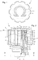
- figure 1 which is a top view of the crown 1, we can distinguish the logo L "Omega" of the applicant, arranged on the outer face 113 of the cover 112 of its cover 11, inside which is housed the device for adjusting the orientation described later using the figures 2 to 4 .
- this L logo is adjusted in a perfectly horizontal position, preferably corresponding to the plane of the caseband of the watch on which the crown is mounted.
- a toothing D which aims to improve the grip of the crown 1 by the user during its use.
- the figure 2 is a sagittal half-section view along the axis of rotation AA of the crown, which reveals the orientation adjustment mechanism according to a preferred embodiment of the invention.
- the crown 1 is shown there in the screwed position on a threaded tube 10, intended to be screwed into a middle part of a watch case - not shown - by means of a first thread 101, while an internal thread 102 cooperates with the thread 21 of a central barrel 2 of tubular shape.
- the internal thread 102 of the tube 10 could, however, consist of a 2nd thread and the thread 21 of the central tube 2 may reciprocally consist of a thread, as for a standard crown screwed directly onto the tube.
- a first seal 103 is provided to be placed between the tube 10 and the middle part for sealing reasons.
- the cover 11 is formed by a cover 112 and an axial skirt 111, which mutually define a central opening 115 inside the crown forming the screwed element 1 - referenced only on the figure 3 for reasons of readability - and in which is arranged the end of the threaded tube 10 integral with the middle part, but also the central barrel 2.
- the threaded central barrel 2 consists of an intermediate element between the cover 11 of the crown 1 and the middle part of the watch as well as a rod (not shown, but conventionally mounted on the lower end 93 of the piston 9 via the internal thread 91 in a blind hole) interacting with the movement.
- the orientation of the central barrel 2 is always identical with respect to the tube 10, and consequently by transitivity to the caseband, in which the latter is also screwed by means of the first thread 101. It is therefore the relative orientation of the central barrel 2 with respect to the cover 11 of crown 1, which determines that of the pattern or logo L inscribed on the upper face 113 of its cover 112.
- This orientation of the central barrel 2 can be determined by acting on gear spokes 24, provided for this purpose and arranged on its lower part and a preferred shape of which is illustrated by figure 3 described later.
- the relative axial position of the central barrel 2 is variable with respect to the cover 11, and it respectively determines an adjustment mode and a locked mode for the orientation of the crown 1.
- the locked mode for the angular orientation of the cover 11, referenced P1 is shown at figure 2
- the mode for adjusting the angular orientation of the cover 11, referenced P2 is illustrated in figure 4 described below.
- the piston 9 housed inside the central barrel 2 can slide against a spring 5 in abutment on an internal surface 114 of the cover 112 of the cover 11, and makes it possible in particular to make the cover 11 stand out from the middle when 'crown 1 is unscrewed from tube 2 when it is used for setting a function (eg setting the time, setting the date or manually winding the movement).
- the axial travel of the piston 9 along the axis AA of rotation of the crown 1 is limited by a stop 22 arranged at the bottom of the central barrel 2, on which is positioned a first shoulder 92 of the piston 9.
- the piston 9 comes into abutment when the crown 1 is unscrewed from the tube 10, as illustrated on figure 4 described below.
- This second seal 7 is compressed on a portion of the tube 10, as shown in a figure 1 .
- the two rings 6 and 8 for retaining the second seal 7 could be replaced by an annular groove formed in the axial skirt 111 of the cover 11 and which would be directed towards the screwed tube 10.
- the cover 11 is assembled to the central barrel 2 so that they are usually integral in rotation, as in the locking position P1 at rest illustrated in figure 2 ; this assembly is made so as to be detachable or reversible.
- This rotational solidarity is obtained by means of the first and second flat friction surfaces 231, 31 preferably arranged on annular wear parts mounted respectively on the central barrel 2 and the cover 11 of the crown, such as for example a flange 23 fixed at the level of the upper end of the central barrel 2 and an annular orientation part 3 fixed to the inside of the cover 11, for example by welding, crimping or any other suitable means.
- the collar 23 of the central barrel 2 and the annular orientation part 3 thus form a preferred embodiment for the first part and the second part integral with the cover 11 of the crown 1 on which the friction surfaces are arranged in mutual contact.
- the advantage of choosing wearing parts to arrange the first and second flat friction surfaces 231,31 is twofold: on the one hand, it makes it possible to choose materials different from those of the cover 11 and of the central barrel 2 for the collar 23 and the orientation part 3, with better tribological properties (such as for example a composite material, mixture of a metal alloy and a ceramic, of the DMC “dual matrix composite” type having particularly high friction coefficients) , and on the other hand such a modular construction makes it possible to replace only the necessary part of the parts worn by friction during possible overhaul or repair services.
- the return means consist of a flat spring 4, with a thickness e1 of at most 0.2mm, arranged between a second shoulder 232 arranged on the collar and a third shoulder 1141 with a surface interior 114 of the cover 111, substantially planar.
- the depth e2 of the third shoulder 1141 makes it possible to define the maximum axial stroke of the central barrel 2 on which the collar 23 is fixed, while the second shoulder 232 arranged on the collar 23 makes it possible to provide a larger lever arm to the flat spring and thus deform more easily.
- the width of the shoulder makes it possible to adjust this lever arm and thus to adjust the force to be applied to disengage the first and second friction surfaces 31, 231 from one another.
- the overall height inside the crown due to such return means is therefore equal to a maximum of 0.4 mm, that is to say much less than with usual elastic springs, such as for example a curved spring.
- the second plane friction surface 31 not on a dedicated part such as the annular orientation part 3 but directly on an upper surface of the spacer, c 'that is to say the first ring 6.
- the force F1 exerted by the return means acts in the direction of the axis of rotation AA, downwards, which would correspond to the inside of the caseband for a crown in the mounted position.
- Such an orientation of the force F1 makes it impossible for the user to change the orientation of the crown 1, which can only act on the cover 11 and thus never generate a force F2 tending to exit the central barrel 2 from the tube 10, as explained below in light of the figure 4 .
- the force F1 exerted by the return means is exerted in the direction of the axis of rotation AA, which is vertical, while the first and second friction surfaces 231, 31 are arranged in a horizontal plane.
- Such an arrangement makes it possible to maximize the mutual plating force between these surfaces and consequently the securing in rotation of the cover 11 and of the central barrel 2, which depends solely on the frictional forces between the friction surfaces.
- the intensity of these friction forces depends directly on the norm of the reaction to the force exerted by the return means F1, which will be all the greater as the latter is exerted in a direction normal to the friction surfaces. Consequently, it is preferably possible to arrange, more generally in the context of the present invention, the return elements so that they exert a force in a direction perpendicular to the plane of contact between the first and second friction surfaces 231, 31.
- the figure 3 shows a bottom view of the crown along the cutting axis BB shown in figure 2 .
- the peripheral part of this figure shows the central opening 115 of the crown 1 in which the screwed tube 10 is engaged, while we can distinguish the lower end of the central barrel 2, which has an opening of hexagonal section.
- This opening is intended to cooperate with the lower end of the piston 93, inside which one can see the thread 91 for connection with a rod (not shown) interacting with the movement.
- the lower end of the piston 93 in this case also takes a hexagonal shape of corresponding size, such that the central barrel 2 and the piston 9 are integral in rotation at least in the position for adjusting the orientation P2 of the crown. .
- the arrangement of a particular hexagonal section makes it possible to easily manipulate the angular orientation of the central barrel 2 when the crown is unscrewed from the tube 10, as on the figure 4 described in the following paragraph, with a tool such as a traditional Allen key.
- Other sections for the opening made in the bottom of the central barrel for example square or triangular type are also possible to perform this manipulation, depending on the tool that one wishes to favor.
- Due to the torsional stresses between the piston 9 and the central barrel 2 when acting directly on the piston 9 to adjust the angular orientation of the crown 1, the preferred embodiment described provides for the arrangement of gear spokes. 24 at the level of the lower periphery of the central barrel 2 for driving it in rotation using a key having teeth of corresponding shape engaged on the spokes. The number of spokes and their depth depends on the moment that one wishes to apply in torsion to the barrel, on the figure 3 we can distinguish 8.
- the figure 4 shows crown 1 of the figure 2 in the adjustment position P2 because the return means used, here the flat spring 4, are compressed by applying a force F2, in the opposite direction to the force F1, using a key 20 engaged on the spokes d 'gear 24 of the central barrel 2 such that the first and second planar friction surfaces 231, 31 are no longer in mutual contact.
- the axial stroke of the central barrel 2 is determined by the depth e2 of the third shoulder 1141 of the internal surface of the cover 114, which is of the order of at most a few tenths of a millimeter.
- figure 4 are identical to those of the figure 2 ; we can however notice that, unlike the figure 2 , the spring 5 of the piston 9 can extend since there is no longer any axial stress either via the thread 21 for the position of the cover 11 or by the indexed position of the winding stem on which is intended to be mounted the piston 9. It can be noted however that it is not the compressed or extended position of the spring 5 of the piston 9 which determines in which position P1 of locking or P2 of orientation adjustment the crown is located, this position being defined only by the position of the return means 4.
- the flat spring 4 is determined such that the passage from position P1 to position P2 requires the exercise of a force F2 against the return means 4 of an intensity twice greater than the force F1 exerted by the return means at rest, that is to say in the locking position P1, so that any accidental handling error is excluded for the orientation of the crown 1.
- the force F1 exerted by the flat spring 4 is of the order of 14 Newton, that is to say much greater than the force required to change the axial position of a conventional zipper, which in general is much lower at around ten Newtons
- the 'stroke element l can consist of a flat spring made no longer in an elastic material, but in a shape memory alloy (SMA), which would have the consequence of replacing the restoring force F2 by a temperature gradient to release the rotation locking link.
- SMA shape memory alloy
- the transition temperature should in this case be well below normal operating temperatures, preferably below -30 degrees.
- the embodiment described with the aid of the figures and the flat spring 4, elastic or with shape memory, has the advantage of requiring only a small space between the upper surface of the central barrel 2 and the internal surface of the cover 114 in the central opening 115, equal to the sum of the thickness e1 of the flat spring 4 and the depths of the shoulder e2 of the internal surface of the cover 1141.
- a minimum clearance must be arranged to ensure the possibility of an axial displacement of the central barrel 2 relative to the cover 11
- other types of return means for example magnetized surfaces near the friction surfaces, such as for example a part of the collar 23 and a part of the annular orientation part 3, or even coincides with the first and second friction surfaces 231, 31 machined from a ferromagnetic material.
- the advantage of using magnetic return means makes it possible to dispense with the use of a dedicated additional part, which allows an additional gain in volume in the ring 1, in particular a gain in height equal to the thickness e1 of the flat spring 4, and therefore further improves the overall compactness of the system.
- the use of magnetic friction surfaces can be employed not only as an alternative to a flat spring, but as a complement in order to increase the return force F1 in the rest position where the cover 11 of the crown 1 is integral with the central barrel 2, and thus improve the frictional forces without having to increase the contact surfaces.
- cover 11 attached to the central barrel 2 allows the crown manufacturer to have a stock of such barrels and to use them with different covers 11 bearing different patterns or other elements such as precious stones or the like, or having external non-cylindrical shapes, for example square, oval or any other particular geometric shape.
- the claimed screwed element may also consist, for example, of a valve, manual or automatic, a valve, a pusher. , a corrector or an adjustable background.
Landscapes
- Physics & Mathematics (AREA)
- General Physics & Mathematics (AREA)
- Transmission Devices (AREA)
- Electric Clocks (AREA)
Description
- La présente invention concerne un dispositif pour régler l'orientation d'éléments vissés pour pièces d'horlogerie et plus particulièrement pour des couronnes comportant un motif ou un logo sur leur face d'extrémité et dans lesquelles le motif peut être orienté à souhait.
- Les couronnes vissées sont couramment utilisées pour équiper des montres dans le but d'améliorer l'étanchéité de celles-ci au niveau de leur tige de remontage ou de commande. Ce type de couronne a la particularité de pouvoir prendre une position dévissée dans laquelle la montre peut être remontée, mise à l'heure etc. et une position vissée dans laquelle la couronne est vissée et bloquée sur un tube chassé ou vissé dans la carrure de la boîte de montre afin de comprimer un joint d'étanchéité, améliorant ainsi l'étanchéité de la montre. La position vissée est donc celle qui correspond à la position normale lorsque la montre est portée et qui est plus ou moins toujours la même à l'usure du joint d'étanchéité près.
- La fabrication et le montage de ces couronnes vissées sur des boites de montre sont bien connus. Toutefois, les procédés de montage de ces couronnes sont mal adaptés aux couronnes vissées portant sur leur face d'extrémité une inscription ou un motif, par exemple un logo, une marque de fabrique ou un signe analogue. En effet, les procédés de montage connus ne permettent généralement pas d'amener la couronne dans une orientation déterminée par rapport à la boîte après leur vissage, ce qui nuit à l'esthétique de la boîte lorsqu'une inscription est apposée sur la face d'extrémité de la couronne. Cette situation est bien entendu inacceptable lorsque ces couronnes équipent des produits de luxe et de haute qualité.
- Pour remédier à ces inconvénients en termes de fiabilité d'orientation d'un logo, le document
EP1411401 décrit une couronne particulière comprenant, sur sa face supérieure externe, un substrat orientable par rapport à une tête formée par un corps central et une jupe latérale, le substrat étant muni d'une inscription et pouvant être désolidarisé en rotation de la tête de la couronne lorsqu'on exerce une pression allant à l'encontre de moyens de freinage. L'inconvénient de cette solution est qu'elle nécessite, d'une part, une structure de couronne non conventionnelle selon laquelle le logo orientable n'est pas formé de façon monobloc avec la tête de la couronne; d'autre part, cette solution est peu robuste par rapport aux chocs, ces derniers pouvant également exercer une force de pression sur le substrat et donc le réorienter intempestivement par rapport au corps de la couronne. Lors d'une manipulation de la couronne il est du reste nécessaire de prendre de nombreuses précautions pour ne faire intervenir aucune force de pression vers la carrure si on veut éviter une rotation involontaire du substrat, ce qui en rend l'usage assez malcommode. - Plusieurs autres solutions ont été proposées avec des couronnes plus conventionnelles, comprenant un capot creux sur une face externe duquel le logo à orienter est usiné, et à l'intérieur duquel le dispositif d'orientation est agencé. Selon le document
EP 1 124 167 A1 par exemple, une bague en alliage à mémoire de forme est placée soit entre la carrure et un tube, soit entre la couronne et un tube pour ajuster, dans une position ou orientation déterminée, une couronne après vissage de celle-ci sur le tube. En jouant sur la déformation de la bague, en particulier en diminuant son diamètre en soumettant la montre à des températures déterminées, un jeu temporaire entre la carrure et le tube respectivement entre la couronne et le tube peut être créé, ce qui permet un ajustement angulaire de la couronne dans sa position vissée. Un inconvénient de cette solution réside dans l'encombrement additionnel de la bague, qui doit être pris en compte dans le dimensionnement du dispositif d'orientation, et détermine un volume global nécessairement plus grand pour la couronne que pour une couronne standard. Par ailleurs, les alliages à mémoire de forme ne sont pas couramment disponibles sous forme de barres de faibles dimensions, de sorte qu'il est difficile et coûteux d'usiner les bagues en question dans les faibles dimensions requises pour les applications concernées. Enfin, ce processus n'est destiné qu'au montage initial de la couronne par le fabricant de la montre, mais pas pour des opérations de réglage ultérieures de l'orientation de la couronne, qui risqueraient d'endommager d'autres pièces de la montre, sensibles aux variations de température. - Le document
EP2182417 propose un dispositif alternatif pour l'orientation d'une couronne vissée avec un capot logoté, comprenant 3 tubes dont deux sont orientés mutuellement l'un par rapport à l'autre à l'aide de dentures qui sont maintenues en contact par l'intermédiaire d'un écrou. Cette solution permet certes des corrections du réglage de l'orientation de la couronne après le montage initial en dévissant l'écrou, mais s'avère particulièrement encombrante car elle nécessite une ouverture plus profonde à l'intérieur de la couronne pour y placer cet écrou. Par ailleurs, le réglage de l'orientation ne peut pas être effectué de façon modulaire sur une couronne dissociée de la boîte, puisque certains éléments d'indexation sont solidaires d'un tube vissé dans la carrure. - Le document
EP1701225 décrit une couronne orientable vissée avec un capot conventionnel sur lequel figure une inscription, et une tête solidaire d'une tige de remontoir. La tête et le capot sont solidarisés en rotation à l'aide de surfaces tronconiques maintenues en contact mutuel à l'aide d'un élément élastique, et le réglage de la position angulaire du capot est effectué en retirant axialement ce dernier par rapport à la carrure selon l'axe longitudinal de la couronne. Etant donné que la solidarité en rotation du capot par rapport à la tête n'est assurée que par les seules forces de friction entre les surfaces tronconiques, ces surfaces doivent s'étendre sur une superficie très importante pour garantir le maintien du capot notamment lorsque les forces de compression exercées par l'élément élastique s'estompent progressivement sur la durée de vie de la montre sur laquelle la couronne est montée. Cette solution n'est ainsi pas adaptée pour des couronnes de très petite taille ou de hauteur réduite. - Enfin, on mentionne le document
WO 2012/168243 A1 qui représente de l'art antérieur au sens de l'article 54(3) CBE. Dans ce document, un capot de couronne coopère avec un élément interne. Cette coopération n'est pas réalisée par friction. - La présente invention a pour but de remédier aux inconvénients de l'art antérieur susmentionné en fournissant un dispositif pour l'orientation d'un élément vissé tel une couronne traditionnelle de construction simple et économique, comportant un motif tel qu'un logo ou une marque et dans laquelle la position du logo ou de la marque apposée sur la face d'extrémité dudit élément puisse aisément être ajustée dans une position ou orientation déterminée et dont la taille puisse être réduite.
- A cet effet, l'invention a pour objet un élément vissé orientable tel que défini dans la revendication 1 annexée.
- Des réalisations préférées sont définies dans les revendications dépendantes.
- L'avantage de la coopération de surfaces de friction planes, bien que non naturelle pour l'homme du métier en raison de la diminution des surfaces de contact qu'elle implique, est qu'elle procure un avantage de compacité à l'élément vissé. Cette solution est ainsi particulièrement adaptée à des pièces de taille très réduite.
- Selon un mode de réalisation préférentiel, le sens des forces exercées par les moyens de rappel ainsi que leur intensité sont déterminés de telle sorte que ce réglage ne puisse être effectué que par le fabricant lors du montage ou par exemple lors d'un service de révision, mais pas par l'utilisateur de la montre lui-même, sans l'aide d'un outil. Ainsi toute erreur de manipulation et/ou tout changement d'orientation intempestif, suite par exemple à un choc, peut être évité.
- D'autres caractéristiques et avantages de la présente invention apparaîtront dans la description suivante d'un mode de réalisation préféré, présenté à titre d'exemple non limitatif en référence aux dessins annexés, dans lesquels:
- la
figure 1 montre une vue de dessus d'un élément vissé sous forme d'une couronne orientable, pourvue d'un logo sur la face externe du couvercle de son capot; - la
figure 2 montre une vue en demi-coupe de la couronne orientable de lafigure 1 pourvue d'un dispositif de réglage d'orientation selon un mode de réalisation préférentiel de l'invention, au repos; - la
figure 3 montre une vue de dessous de la couronne orientable de lafigure 1 , montrant plus particulièrement les sections externes d'un piston et d'un canon; - la
figure 4 est une vue en coupe similaire à lafigure 2 , la couronne étant représentée dans une position dans laquelle son capot est désolidarisé de la tête en vu de l'orientation angulaire dans une position déterminée du motif porté par le capot, en position désolidarisée de la carrure. - Sur le mode de réalisation préférentiel illustré par l'ensemble des figures qui suivent, l'élément vissé orientable consiste en une couronne désignée par la référence générale 1. Sur la
figure 1 , qui est une vue de dessus de la couronne 1, on peut distinguer le logo L « Omega » de la demanderesse, agencé sur la face externe 113 du couvercle 112 de son capot 11, à l'intérieur duquel est logé le dispositif du réglage de l'orientation décrit plus loin à l'aide desfigures 2 à 4 . Pour des raisons esthétiques, ce logo L est ajusté en position parfaitement horizontale correspondant de préférence au plan de la carrure de la montre sur laquelle est montée la couronne. Sur cette figure on peut également distinguer, sur le pourtour extérieur du capot, une denture D qui vise à améliorer la préhension de la couronne 1 par l'utilisateur lors de son utilisation. - La
figure 2 est une vue en demi-coupe sagittale le long de l'axe de rotation A-A de la couronne, qui dévoile le mécanisme de réglage de l'orientation selon un mode de réalisation préférentiel de l'invention. La couronne 1 y est représentée en position vissée sur un tube fileté 10, destiné à être vissé dans une carrure d'une boîte de montre - non représentée - au moyen d'un premier filetage 101, tandis qu'un taraudage 102 coopère avec le filetage 21 d'un canon central 2 de forme tubulaire. Selon un mode de réalisation alternatif, le taraudage 102 du tube 10 pourrait toutefois consister en un 2e filetage et le filetage 21 du canon central 2 pourrait réciproquement consister en un taraudage, comme pour une couronne classique vissée directement sur le tube. Un premier joint 103 est prévu pour être disposé entre le tube 10 et la carrure pour des raisons d'étanchéité. - Le capot 11 est formé par un couvercle 112 et une jupe axiale 111, qui définissent mutuellement une ouverture centrale 115 à l'intérieur de la couronne formant l'élément vissé 1 - référencé uniquement sur la
figure 3 pour des raisons de lisibilité - et dans laquelle est disposée l'extrémité du tube fileté 10 solidaire de la carrure, mais également le canon central 2. Selon le mode de réalisation préférentiel illustré, le canon central 2 fileté consiste en un élément intermédiaire entre le capot 11 de la couronne 1 et la carrure de la montre ainsi qu'une tige (non représentée, mais classiquement montée sur l'extrémité inférieure 93 du piston 9 par l'intermédiaire du taraudage 91 dans un trou borgne) interagissant avec le mouvement. En position vissée sur le tube 10, l'orientation du canon central 2 est toujours identique par rapport au tube 10, et par conséquent par transitivité à la carrure, dans laquelle ce dernier est également vissé par l'intermédiaire du premier filetage 101. C'est donc l'orientation relative du canon central 2 par rapport au capot 11 de la couronne 1, qui détermine celle du motif ou du logo L inscrit sur la face supérieure 113 de son couvercle 112. Cette orientation du canon central 2 peut être déterminée en agissant sur des rayons d'engrenage 24, prévus à cet effet et disposés sur sa partie inférieure et dont une forme préférentielle est illustrée par lafigure 3 décrite plus loin. - La position axiale relative du canon central 2 est variable par rapport au capot 11, et elle détermine respectivement un mode de réglage et un mode verrouillé pour l'orientation de la couronne 1. Le mode verrouillé pour l'orientation angulaire du capot 11, référencé P1, est illustré à la
figure 2 , tandis que le mode de réglage de l'orientation angulaire du capot 11, référencé P2, est illustré à lafigure 4 décrite ci-après. - Le piston 9 logé à l'intérieur du canon central 2 peut coulisser à l'encontre d'un ressort 5 en butée sur une surface interne 114 du couvercle 112 du capot 11, et permet notamment de faire ressortir le capot 11 de la carrure lorsqu'on dévisse la couronne 1 du tube 2 lors de son utilisation pour le réglage d'une fonction (p.ex. une remise à l'heure, le réglage du quantième ou un remontage manuel du mouvement). La course axiale du piston 9 selon l'axe A-A de rotation de la couronne 1 est limitée par une butée 22 agencée au bas du canon central 2, sur laquelle vient se positionner un premier épaulement 92 du piston 9. Le piston 9 vient en butée lorsque la couronne 1 est dévissée du tube 10, comme illustré sur la
figure 4 décrite ci-après. Un deuxième joint 7, comme par exemple un O-Ring, est interposé entre le tube fileté 10 et la jupe axiale 111 du capot 11 de manière à garantir l'étanchéité par rapport aux éléments internes de la couronne; en position vissée de la couronne, ce deuxième joint 7 est maintenu axialement entre une première bague 6, ou entretoise, et une deuxième bague 8, aussi communément appelée deckring, qui le recouvre au niveau de la surface inférieure de la couronne 1. Ce deuxième joint 7 est compressé sur une portion du tube 10, comme montré à afigure 1 . A titre d'alternative, les deux bagues 6 et 8 de maintien du deuxième joint 7 pourraient être remplacées par une gorge annulaire ménagée dans la jupe axiale 111 du capot 11 et qui serait dirigée vers le tube vissé 10. - Selon l'invention, le capot 11 est assemblé au canon central 2 de façon à ce qu'ils soient habituellement solidaires en rotation, comme à la position P1 de verrouillage au repos illustrée à la
figure 2 ; cet assemblage est réalisé de manière à être détachable ou réversible. Cette solidarité en rotation est obtenue par l'intermédiaire des premières et deuxièmes surfaces planes de friction 231,31 agencées de préférence sur des pièces d'usure annulaires montées respectivement sur le canon central 2 et le capot 11 de la couronne, comme par exemple une collerette 23 fixée au niveau de l'extrémité supérieure du canon central 2 et une pièce d'orientation annulaire 3 fixée sur l'intérieur du capot 11 par exemple par soudage, sertissage ou tout autre moyen approprié. La collerette 23 du canon central 2 et la pièce d'orientation annulaire 3 forment ainsi un mode de réalisation préférentiel pour la première pièce et la deuxième pièce solidaire du capot 11 de la couronne 1 sur lesquelles sont agencées les surfaces de friction en contact mutuel. L'intérêt de choisir des pièces d'usure pour agencer les premières et deuxièmes surfaces planes de friction 231,31 est double: d'une part il permet de choisir des matériaux différents de ceux du capot 11 et du canon central 2 pour la collerette 23 et la pièce d'orientation 3, avec de meilleures propriétés tribologiques (comme par exemple un matériau composite, mélange d'un alliage métallique et d'une céramique, du type DMC « dual matrix composite » présentant des coefficients de frottement particulièrement élevés), et d'autre part une telle construction modulaire permet de ne remplacer que la partie nécessaire des pièces usées par les frottements lors de services de révision ou de réparation éventuels. - Des moyens de rappel distincts de ceux associés à l'extension du piston tendent à rendre solidaire en rotation le capot 11 et le canon central 2 en exerçant une force F1 de compression entre la collerette 23 et la bague 3 d'orientation, et maintenir ainsi les premières et deuxième surfaces de friction 231,31 en contact mutuel dans la position P1 de verrouillage. Selon le mode de réalisation préférentiel illustré, les moyens de rappel consistent en un ressort plat 4, d'une épaisseur e1 d'au maximum 0.2mm, disposé entre un deuxième épaulement 232 agencé sur la collerette et un troisième épaulement 1141 d'une surface intérieure 114 du couvercle 111, sensiblement plane. La profondeur e2 du troisième épaulement 1141 permet de définir la course axiale maximale du canon central 2 sur lequel est fixé la collerette 23, tandis que le deuxième épaulement 232 agencé sur la collerette 23 permet de procurer un bras de levier plus important au ressort plat et ainsi se déformer plus facilement. La largeur de l'épaulement permet de régler ce bras de levier et ainsi d'ajuster la force à appliquer pour dégager les première et deuxième surfaces de friction 31,231 l'une de l'autre. L'encombrement en hauteur à l'intérieur de la couronne dû à de tels moyens de rappel est donc égal au maximum à 0.4mm, soit beaucoup moins qu'avec des ressorts élastiques usuels, comme par exemple un ressort galbé. Pour gagner encore de la place en hauteur, il est également possible d'agencer la deuxième surface de friction de plane 31 non pas sur une pièce dédiée comme la pièce d'orientation annulaire 3 mais directement sur une surface supérieure de l'entretoise, c'est-à-dire la première bague 6. Selon le mode de réalisation illustré, la force F1 exercée par les moyens de rappel agit dans la direction de l'axe de rotation A-A, vers le bas, ce qui correspondrait à l'intérieur de la carrure pour une couronne en position montée. Une telle orientation de la force F1 rend impossible tout changement d'orientation de la couronne 1 par l'utilisateur, qui ne peut agir que sur le capot 11 et ainsi jamais générer de force F2 tendant à sortir le canon central 2 du tube 10, comme expliqué ci-après à la lumière de la
figure 4 . - Selon le mode de réalisation préférentiel illustré par la
figure 2 , la force F1 exercée par les moyens de rappel est exercée selon la direction de l'axe de rotation A-A, qui est vertical, tandis que les première et deuxième surfaces de friction 231,31 sont disposées dans un plan horizontal. Un tel agencement permet de maximiser la force de plaquage mutuel entre ces surfaces et par conséquent la solidarisation en rotation du capot 11 et du canon central 2, qui dépend uniquement des forces de frottement entre les surfaces de friction. Or l'intensité de ces forces de frottement dépend directement de la norme de la réaction à la force exercée par les moyens de rappel F1, qui sera d'autant plus grande que cette dernière est exercée selon une direction normale aux surfaces de friction. Par conséquent, on pourra de préférence agencer, plus généralement dans le cadre de la présente invention, les éléments de rappel de telle sorte qu'ils exercent une force dans une direction perpendiculaire au plan de contact entre les première et deuxième surfaces de friction 231, 31. - La
figure 3 montre une vue de dessous de la couronne selon l'axe de coupe B-B illustré à lafigure 2 . La partie périphérique de cette figure montre l'ouverture centrale 115 de la couronne 1 dans laquelle est engagé le tube vissé 10, tandis qu'on peut distinguer l'extrémité inférieure du canon central 2, qui présente une ouverture de section hexagonale. Cette ouverture est destinée à coopérer avec l'extrémité inférieure du piston 93, à l'intérieur duquel on peut voir le taraudage 91 pour la liaison avec une tige (non représentée) interagissant avec le mouvement. L'extrémité inférieure du piston 93 prend dans ce cas également une forme hexagonale de taille correspondante, de telle sorte que le canon central 2 et le piston 9 sont solidaires en rotation au moins dans la position de réglage de l'orientation P2 de la couronne. L'agencement d'une section particulière hexagonale permet de manipuler aisément l'orientation angulaire du canon central 2 lorsque la couronne est dévissée du tube 10, comme sur lafigure 4 décrite au paragraphe suivant, avec un outil comme une clef traditionnelle à 6 pans. D'autres sections pour l'ouverture pratiquée dans le fond du canon central, de type par exemple carrée ou triangulaire sont également envisageables pour effectuer cette manipulation, en fonction de l'outil que l'on souhaitera privilégier. En raison des contraintes en torsion entre le piston 9 et le canon central 2 lorsqu'on agit directement sur le piston 9 pour ajuster l'orientation angulaire de la couronne 1, le mode de réalisation préférentiel décrit prévoit l'agencement de rayons d'engrenage 24 au niveau de la périphérie inférieure du canon central 2 pour son entraînement en rotation à l'aide d'une clef présentant des dents de forme correspondante engagés sur les rayons. Le nombre de rayons et leur profondeur dépend du moment que l'on souhaite appliquer en torsion au canon, sur lafigure 3 on peut en distinguer 8. - La
figure 4 montre la couronne 1 de lafigure 2 en position de réglage P2 car les moyens de rappel utilisés, ici le ressort plat 4, sont compressés par application d'une force F2, de sens opposé à la force F1, à l'aide d'une clef 20 engagée sur les rayons d'engrenage 24 du canon central 2 de telle sorte que les première et deuxième surfaces de friction planes 231, 31 ne sont plus en contact mutuel. La course axiale du canon central 2 est déterminée par la profondeur e2 du troisième épaulement 1141 de la surface interne du couvercle 114, qui est de l'ordre d'au plus quelques dixièmes de millimètres Toutes les pièces illustrées sur lafigure 4 sont identiques à celles de lafigure 2 ; on peut toutefois remarquer que, contrairement à lafigure 2 , le ressort 5 du piston 9 peut s'étendre puisqu'il n'y a plus de contrainte axiale ni par l'intermédiaire du filetage 21 pour la position du capot 11 ni par la position indexée de la tige de remontoir sur laquelle est destiné à être monté le piston 9. On peut remarquer toutefois que ce n'est pas la position compressée ou étendue du ressort 5 du piston 9 qui détermine dans quelle position P1 de verrouillage ou P2 de réglage d'orientation la couronne se trouve, cette position étant définie uniquement par la position des moyens de rappel 4. - Selon un mode de réalisation préférentiel, le ressort plat 4 est déterminé de telle sorte que le passage de la position P1 à la position P2 nécessite l'exercice d'une force F2 à l'encontre des moyens de rappel 4 d'une intensité deux fois supérieure à la force F1 exercée par les moyens de rappel au repos, c'est-à-dire dans la position de verrouillage P1, de telle sorte que toute erreur de manipulation fortuite soit exclue pour l'orientation de la couronne 1. Dans le cas où la force F1 exercée par le ressort plat 4 est de l'ordre de 14 Newton, soit largement supérieure à la force requise pour changer la position axiale d'une tirette classique, qui en général est très inférieure à une dizaine de Newton on pourra par exemple configurer les propriétés plastiques du ressort plat 4 de telle sorte qu'il soit nécessaire d'exercer une force de l'ordre de 28 Newtons pour régler l'orientation de la couronne 1. Afin de diminuer légèrement la valeur de la force F2 souhaitée, pour obtenir une intensité comprise entre 23 et 28 Newtons et faciliter ainsi la manipulation de la couronne lors des opérations de réglage il est également possible de d'ajourer le ressort plat 4. Selon une variante, l'élément de rappel peut consister en un ressort plat réalisé non plus en un matériau élastique, mais dans un alliage à mémoire de forme (shape memory alloy, SMA), ce qui aurait pour conséquence de remplacer la force de rappel F2 par un gradient de température pour libérer la liaison de blocage en rotation. La température de transition devrait dans ce cas là se situer bien en-dessous des températures de service usuelles, soit de préférence en-dessous de -30 degrés.
- On pourra remarquer que selon le mode de réalisation préférentiel décrit aux
figures 2 et4 , il est impossible à l'utilisateur d'effectuer le réglage une fois que la couronne 1 est assemblée au tube 2. En effet, la disposition de la première surface de friction 231 sur la face interne de la collerette 23 et l'exercice de la force F1 vers l'intérieur empêche d'une part toute désolidarisation du capot 11 par rapport au canon central 2 lorsque l'utilisateur tire sur le capot 11 pour déplacer la couronne 1 axialement hors de la carrure, car le déplacement axial du capot 11 dans cette direction tend alors à plaquer les surfaces de friction l'une sur l'autre. D'autre part, presser le capot 11 vers la carrure ne permettrait pas non plus de désolidariser les surfaces de friction l'une de l'autre: si la couronne 1 ne se trouve pas dans sa position proximale par rapport à la carrure, c'est-à-dire la position axiale plus proche possible de la carrure, les moyens de rappel peuvent dans ce cas être compressés, mais la force à exercer pour désolidariser les dentures devrait être largement supérieure à celle qui ramène le capot 11 dans sa position proximale par rapport à la carrure en entraînant la tige de remontoir. Le capot serait donc d'abord ramené dans sa position proximale, avant que les surfaces de friction ne puissent être désolidarisées. Or dans cette position, plus aucun mouvement axial n'est possible vers l'intérieur de la carrure mis à part par vissage sur le tube 10, et dès lors les moyens de rappel ne peuvent plus être comprimés pour permettre de désengager les surfaces de friction. De cette façon, toute erreur de manipulation est évitée et l'orientation de la couronne ne pourra être changée que lorsque celle-ci est dévissée du tube 2 et qu'un outil lui est appliqué, comme par exemple la clef 20 sur les rayons d'engrenage 24, en appliquant la force F2 nécessaire à la désolidarisation du capot 11 puis le moment de torsion pour ajuster la position angulaire du canon central 2 par rapport au capot 11. - En ce qui concerne les moyens de rappel, le mode de réalisation décrit à l'aide des figures et le ressort plat 4, élastique ou à mémoire de forme, présente l'avantage de ne requérir qu'un espace restreint entre la surface supérieure du canon central 2 et la surface interne du couvercle 114 dans l'ouverture centrale 115, égal à la somme de l'épaisseur e1 du ressort plat 4 et la profondeurs de l'épaulement e2 de la surface interne du couvercle 1141. Bien qu'un jeu minimal doive être aménagé pour garantir la possibilité d'un déplacement axial du canon central 2 par rapport au capot 11, d'autres types de moyens de rappel, par exemple des surfaces aimantées à proximité des surfaces de friction, comme par exemple une partie de la collerette 23 et une partie de la pièce annulaire d'orientation 3, voire même confondues avec les première et deuxième surfaces de friction 231,31 usinées dans un matériau ferromagnétique. L'avantage d'utiliser des moyens de rappel magnétiques permet de dispenser de l'usage d'une pièce additionnelle dédiée, ce qui permet un gain additionnel en volume dans la couronne 1, notamment un gain en hauteur égal à l'épaisseur e1 du ressort plat 4, et donc améliore encore la compacité globale du système. Toutefois, l'usage de surfaces de friction magnétiques peut être employé non pas seulement à titre d'alternative pour un ressort plat, mais à titre complémentaire afin d'augmenter la force F1 de rappel dans la position de repos où le capot 11 de la couronne 1 est solidaire du canon central 2, et améliorer ainsi les forces de friction sans devoir augmenter les surfaces de contact.
- On notera que l'utilisation d'un capot 11 rapporté sur le canon central 2 permet au fabricant de couronnes d'avoir un stock de tels canons et de les utiliser avec différents capots 11 portant des motifs différents ou d'autres éléments tels que des pierres précieuses ou analogues, ou ayant des formes extérieures non cylindriques par exemple carrée, ovale ou tout autre forme géométrique particulière.
- Bien que l'invention revendiquée ait été décrite principalement en relation avec l'exemple non limitatif d'une couronne 1, on comprendra que l'élément vissé revendiqué pourra également consister par exemple en une soupape, manuelle ou automatique, une valve, un poussoir, un correcteur ou encore un fond orientable.
Claims (12)
- Elément vissé orientable comprenant un capot (11) formé d'un couvercle (112) solidaire d'une jupe latérale (111), et un dispositif pour le réglage de l'orientation angulaire dudit capot (11) par rapport à une carrure de montre, caractérisé en ce que ledit dispositif pour le réglage de l'orientation angulaire dudit capot (11) comprend une première pièce pourvue d'une première surface de friction (231) plane, une deuxième pièce solidaire dudit capot (11) pourvue d'une deuxième surface de friction (31) plane et des moyens de rappel tendant à rendre solidaire en rotation ledit capot (11) et ladite première pièce, ledit capot (11) et ladite première pièce étant mobiles axialement l'un par rapport à l'autre entre une première position (P1) dans laquelle ladite première surface de friction (231) plane et ladite deuxième surface de friction (31) plane sont plaquées mutuellement l'une contre l'autre par lesdits moyens de rappel, et une deuxième position (P2) dans laquelle ladite première surface de friction (231) plane et ladite deuxième surface de friction (31) plane ne sont plus en contact, lesdits moyens de rappel, lesdites première et deuxième surface de friction (231,31) étant agencés de telle sorte que ledit capot (11) soit solidaire en rotation par rapport à ladite première pièce dans ladite première position (P1) et libre de tourner autour de l'axe de rotation (A-A) dudit élément vissé (1) orientable dans ladite deuxième position (P2), lesdites première et deuxième surfaces de friction (231,31) étant agencées dans un plan horizontal orthogonal à l'axe de rotation (A-A) de l'élément vissé (1).
- Elément vissé orientable selon la revendication 1, ledit couvercle (112) et ladite jupe latérale (111) définissant une ouverture centrale (115) agencée pour loger un canon central (2) solidaire de ladite première pièce.
- Elément vissé orientable selon l'une des revendications précédentes, ladite première pièce pourvue d'une première surface de friction (231) plane formant une collerette (23) d'usure interchangeable autour d'un canon central (2).
- Elément vissé orientable selon l'une des revendications précédentes, ladite deuxième pièce solidaire dudit capot (11) pourvue d'une deuxième surface de friction (31) plane étant une pièce d'orientation annulaire (3) d'usure interchangeable.
- Elément vissé orientable selon l'une des revendications précédentes, caractérisé en ce que lesdits moyens de rappel exercent une force (F1) axiale selon l'axe de rotation A-A dudit élément vissé, et orientée vers l'intérieur.
- Elément vissé orientable selon l'une des revendications précédentes, caractérisé en ce que lesdits moyens de rappel consistent en un ressort plat (4) élastique ou à mémoire de forme.
- Elément vissé orientable selon la revendication 6, ledit ressort plat (4) ayant une épaisseur (e1) d'au maximum 0.1mm et étant disposé entre un premier épaulement (1141) d'une surface intérieure (114) d'un couvercle (111) dudit capot (11), ledit épaulement (1141) ayant une profondeur (e2) d'au maximum 0.2mm, et un deuxième épaulement (232) de ladite première pièce.
- Elément vissé orientable selon l'une des revendications précédentes, caractérisé en ce que lesdites premières et deuxièmes surfaces de friction (231,31) sont aimantées.
- Elément vissé orientable selon l'une des revendications précédentes, caractérisé en ce qu'il contient un piston (9) solidaire d'une tige reliée au mouvement d'une montre, ledit piston (9) étant logé mobile axialement à l'intérieur d'un canon central (2), la course dudit piston (9) étant limitée par une butée (22) dudit canon central (2).
- Elément vissé orientable selon la revendication 9, ledit piston (9) présentant une extrémité inférieure (93) de forme hexagonale et ledit canon central (2) une ouverture de forme correspondante.
- Elément vissé orientable selon l'une des revendications 9 ou 10, ledit canon central (2) présentant des rayons d'engrenage (24) périphériques pour le réglage de l'orientation.
- Elément vissé orientable selon l'une des revendications précédentes, caractérisé en ce que le passage de la position (P1) à la position (P2) nécessite l'exercice d'une force (F2) à l'encontre des moyens de rappel d'une intensité comprise entre 23 et 28 Newtons.
Priority Applications (1)
| Application Number | Priority Date | Filing Date | Title |
|---|---|---|---|
| EP13776993.1A EP2915012B1 (fr) | 2012-11-02 | 2013-10-03 | Dispositif pour l'orientation d'un élément vissé d'une pièce d'horlogerie |
Applications Claiming Priority (3)
| Application Number | Priority Date | Filing Date | Title |
|---|---|---|---|
| EP12191108 | 2012-11-02 | ||
| PCT/EP2013/070650 WO2014067743A1 (fr) | 2012-11-02 | 2013-10-03 | Dispositif pour l'orientation d'un element visse d'une piece d'horlogerie |
| EP13776993.1A EP2915012B1 (fr) | 2012-11-02 | 2013-10-03 | Dispositif pour l'orientation d'un élément vissé d'une pièce d'horlogerie |
Publications (2)
| Publication Number | Publication Date |
|---|---|
| EP2915012A1 EP2915012A1 (fr) | 2015-09-09 |
| EP2915012B1 true EP2915012B1 (fr) | 2021-03-31 |
Family
ID=47263084
Family Applications (1)
| Application Number | Title | Priority Date | Filing Date |
|---|---|---|---|
| EP13776993.1A Active EP2915012B1 (fr) | 2012-11-02 | 2013-10-03 | Dispositif pour l'orientation d'un élément vissé d'une pièce d'horlogerie |
Country Status (5)
| Country | Link |
|---|---|
| US (1) | US9317014B2 (fr) |
| EP (1) | EP2915012B1 (fr) |
| JP (1) | JP5931294B2 (fr) |
| CN (1) | CN104769511B (fr) |
| WO (1) | WO2014067743A1 (fr) |
Cited By (1)
| Publication number | Priority date | Publication date | Assignee | Title |
|---|---|---|---|---|
| EP4206827A1 (fr) * | 2021-12-30 | 2023-07-05 | Meco S.A. | Soupape de securite pour montre |
Families Citing this family (17)
| Publication number | Priority date | Publication date | Assignee | Title |
|---|---|---|---|---|
| CH712742A2 (fr) * | 2016-07-26 | 2018-01-31 | Omega Sa | Sous-ensemble d'habillage pour pièce d'horlogerie, notamment une montre, ou pour bijou. |
| EP3279745B1 (fr) * | 2016-08-02 | 2023-06-14 | Meco S.A. | Couronne vissee orientable |
| EP3287855B1 (fr) * | 2016-08-26 | 2019-05-01 | Meco S.A. | Couronne de reglage pour piece d'horlogerie |
| EP3339966B1 (fr) * | 2016-12-23 | 2020-06-24 | Rolex Sa | Poussoir pour pièce d'horlogerie |
| USD817210S1 (en) * | 2016-12-29 | 2018-05-08 | Omega Ltd. | Dial |
| EP3451071B1 (fr) * | 2017-09-01 | 2020-07-22 | Omega SA | Dispositif à poussoir pour pièce d'horlogerie |
| EP3451079B1 (fr) * | 2017-09-01 | 2020-11-18 | Omega SA | Dispositif pour l'orientation d'une soupape pour pièce d'horlogerie |
| EP3454137B1 (fr) * | 2017-09-07 | 2024-03-06 | Montres Breguet S.A. | Outil d'actionnement d'un correcteur équipant une montre |
| AU201811024S (en) * | 2017-10-17 | 2018-03-15 | Omega Sa Omega Ag Omega Ltd | Watch crown |
| EP3495896A1 (fr) | 2017-12-11 | 2019-06-12 | Barigna SA | Montre munie d'un organe de commande du mécanisme intérieur |
| EP3499320A1 (fr) * | 2017-12-15 | 2019-06-19 | The Swatch Group Research and Development Ltd | Systeme de fermeture/ouverture pour une boite d'une piece d'horlogerie |
| EP3594758A1 (fr) * | 2018-07-09 | 2020-01-15 | Tissot S.A. | Montre pourvue d'une lunette tournante avec systeme de verrouillage de la lunette muni d'une soupape a helium integree |
| EP3805872B1 (fr) * | 2019-10-09 | 2025-11-26 | Meco S.A. | Couronne vissee orientable |
| EP3805874B1 (fr) * | 2019-10-09 | 2023-12-27 | Meco S.A. | Couronne vissee orientable |
| EP3805869B1 (fr) * | 2019-10-09 | 2025-12-24 | Meco S.A. | Couronne vissée |
| EP3869278B1 (fr) * | 2020-02-21 | 2023-03-08 | Montres Breguet S.A. | Dispositif d'embrayage vertical pour piece d'horlogerie |
| EP3923087A1 (fr) * | 2020-06-10 | 2021-12-15 | Meco S.A. | Dispositif d'etancheite |
Family Cites Families (13)
| Publication number | Priority date | Publication date | Assignee | Title |
|---|---|---|---|---|
| FR2471626A1 (fr) * | 1979-12-13 | 1981-06-19 | Suisse Horlogerie | Poussoir miniature |
| CH691936A5 (de) * | 1997-06-11 | 2001-11-30 | Meco Sa Grenchen | Betätigungsmittel mit Dichtung für eine Uhr. |
| CH705649B1 (fr) | 2000-02-08 | 2013-04-30 | Boninchi Sa | Dispositif permettant le réglage de l'orientation d'une couronne à vis d'une montre par rapport à la carrure de la montre. |
| DE20210345U1 (de) * | 2002-07-03 | 2002-12-19 | Damasko, Petra, 93055 Regensburg | Krone für Uhren, insbesondere für Armband- oder Taschenuhren, Kronenanordnung mit einer solchen Krone sowie Werkzeug zum Befestigen eines Einschraubtubus für eine Kronenanordnung an einem Uhrengehäuse |
| EP1411401A1 (fr) | 2002-10-17 | 2004-04-21 | Ks 22 Sa | Couronne à vis pour pièce d'horlogerie |
| WO2005038538A1 (fr) * | 2003-10-21 | 2005-04-28 | Richemont International Sa | Dispositif de commande a couronne-poussoir pour montre |
| EP1701225B1 (fr) * | 2005-03-09 | 2012-02-22 | Boninchi S.A. | Couronne vissée pour pièce d'horlogerie |
| JP5044374B2 (ja) * | 2007-11-26 | 2012-10-10 | セイコーインスツル株式会社 | 携帯時計 |
| EP2107432B1 (fr) * | 2008-04-01 | 2011-06-29 | Montres Rado S.A. | Dispositif de commande à poussoir pour montre |
| CH699877A1 (fr) | 2008-10-31 | 2010-05-14 | Pibor Iso S A | Couronne a visser et procédé d'orientation d'une telle couronne sur une boîte de montre. |
| EP2367075B1 (fr) * | 2010-03-17 | 2017-07-26 | Meco S.A. | Couronne de remontage pour pièce d'horlogerie |
| EP2385432A2 (fr) * | 2010-05-04 | 2011-11-09 | Rolex Sa | Boîte de montre |
| CH705090A2 (fr) | 2011-06-08 | 2012-12-14 | Omega Sa | Dispositif pour l'orientation d'une couronne vissée d'une pièce d'horlogerie. |
-
2013
- 2013-10-03 EP EP13776993.1A patent/EP2915012B1/fr active Active
- 2013-10-03 JP JP2015531612A patent/JP5931294B2/ja active Active
- 2013-10-03 US US14/426,829 patent/US9317014B2/en active Active
- 2013-10-03 WO PCT/EP2013/070650 patent/WO2014067743A1/fr not_active Ceased
- 2013-10-03 CN CN201380057099.2A patent/CN104769511B/zh active Active
Non-Patent Citations (1)
| Title |
|---|
| None * |
Cited By (2)
| Publication number | Priority date | Publication date | Assignee | Title |
|---|---|---|---|---|
| EP4206827A1 (fr) * | 2021-12-30 | 2023-07-05 | Meco S.A. | Soupape de securite pour montre |
| US12359736B2 (en) | 2021-12-30 | 2025-07-15 | Meco Sa | Pressure-relief valve for a watch |
Also Published As
| Publication number | Publication date |
|---|---|
| US9317014B2 (en) | 2016-04-19 |
| EP2915012A1 (fr) | 2015-09-09 |
| CN104769511A (zh) | 2015-07-08 |
| US20150241846A1 (en) | 2015-08-27 |
| WO2014067743A1 (fr) | 2014-05-08 |
| HK1212048A1 (en) | 2016-06-03 |
| CN104769511B (zh) | 2017-06-13 |
| JP5931294B2 (ja) | 2016-06-08 |
| JP2015531875A (ja) | 2015-11-05 |
Similar Documents
| Publication | Publication Date | Title |
|---|---|---|
| WO2014067743A1 (fr) | Dispositif pour l'orientation d'un element visse d'une piece d'horlogerie | |
| EP2718770B1 (fr) | Dispositif pour l'orientation d'une couronne vissee d'une piece d'horlogerie | |
| EP2624076B1 (fr) | Boîte de montre munie d'une lunette orientable et indexée | |
| EP3279745B1 (fr) | Couronne vissee orientable | |
| EP1411401A1 (fr) | Couronne à vis pour pièce d'horlogerie | |
| EP2592500B1 (fr) | Boîte de montre comportant une couronne à mémoire d'orientation | |
| EP2533111B1 (fr) | Dispositif et procédé de fixation d'un élément de montre avec orientation angulaire réglable | |
| EP2746870B1 (fr) | Couronne démontable | |
| EP3839663B1 (fr) | Lunette pour boîte de pièce d'horlogerie ou pour pièce d'horlogerie | |
| WO2015144423A1 (fr) | Systeme de commande pour piece d'horlogerie | |
| EP1701225B1 (fr) | Couronne vissée pour pièce d'horlogerie | |
| EP2182417A2 (fr) | Couronne à visser et procédé d'orientation d'une telle couronne sur une boîte de montre | |
| EP2957964B1 (fr) | Dispositif d'embrayage basculant pour pièce d'horlogerie | |
| EP4198645B1 (fr) | Dispositif de correction multifonction pour pièce d'horlogerie et pièce d'horlogerie comportant un tel dispositif de correction multifonction | |
| EP1890203B1 (fr) | Boîte de montre comprenant un fond et procédé de fixation d'un fond sur une boîte de montre | |
| EP3339966B1 (fr) | Poussoir pour pièce d'horlogerie | |
| CH707158A2 (fr) | Elément vissé orientable, par exemple couronne pour pièce d'horlogerie. | |
| EP2798414B1 (fr) | Ressort pour mouvement horloger | |
| EP2602675A1 (fr) | Mouvement horloger comportant un mécanisme de chronographe à roue à colonnes | |
| EP1727005B1 (fr) | Couronne à visser et procédé d'assemblage d'une telle couronne sur une boîte de montre | |
| EP1947531B1 (fr) | Dispositif de réglage de l'amplitude de déplacement de la bascule d'embrayage d'un chronographe à roue à colonnes | |
| CH712785A2 (fr) | Couronne vissée orientable. | |
| CH709909B1 (fr) | Mécanisme de mise à l'heure et de remontage pour pièce d'horlogerie. | |
| CH719814B1 (fr) | Couronne à verrouillage orienté et boite de montre comportant une telle couronne | |
| CH709408A2 (fr) | Système de commande pour un organe tournant de pièce d'horlogerie. |
Legal Events
| Date | Code | Title | Description |
|---|---|---|---|
| PUAI | Public reference made under article 153(3) epc to a published international application that has entered the european phase |
Free format text: ORIGINAL CODE: 0009012 |
|
| 17P | Request for examination filed |
Effective date: 20150602 |
|
| AK | Designated contracting states |
Kind code of ref document: A1 Designated state(s): AL AT BE BG CH CY CZ DE DK EE ES FI FR GB GR HR HU IE IS IT LI LT LU LV MC MK MT NL NO PL PT RO RS SE SI SK SM TR |
|
| AX | Request for extension of the european patent |
Extension state: BA ME |
|
| DAX | Request for extension of the european patent (deleted) | ||
| STAA | Information on the status of an ep patent application or granted ep patent |
Free format text: STATUS: EXAMINATION IS IN PROGRESS |
|
| 17Q | First examination report despatched |
Effective date: 20200612 |
|
| GRAP | Despatch of communication of intention to grant a patent |
Free format text: ORIGINAL CODE: EPIDOSNIGR1 |
|
| STAA | Information on the status of an ep patent application or granted ep patent |
Free format text: STATUS: GRANT OF PATENT IS INTENDED |
|
| INTG | Intention to grant announced |
Effective date: 20201119 |
|
| GRAS | Grant fee paid |
Free format text: ORIGINAL CODE: EPIDOSNIGR3 |
|
| GRAA | (expected) grant |
Free format text: ORIGINAL CODE: 0009210 |
|
| STAA | Information on the status of an ep patent application or granted ep patent |
Free format text: STATUS: THE PATENT HAS BEEN GRANTED |
|
| AK | Designated contracting states |
Kind code of ref document: B1 Designated state(s): AL AT BE BG CH CY CZ DE DK EE ES FI FR GB GR HR HU IE IS IT LI LT LU LV MC MK MT NL NO PL PT RO RS SE SI SK SM TR |
|
| REG | Reference to a national code |
Ref country code: GB Ref legal event code: FG4D Free format text: NOT ENGLISH Ref country code: CH Ref legal event code: EP |
|
| REG | Reference to a national code |
Ref country code: AT Ref legal event code: REF Ref document number: 1377636 Country of ref document: AT Kind code of ref document: T Effective date: 20210415 |
|
| REG | Reference to a national code |
Ref country code: DE Ref legal event code: R096 Ref document number: 602013076603 Country of ref document: DE |
|
| REG | Reference to a national code |
Ref country code: IE Ref legal event code: FG4D Free format text: LANGUAGE OF EP DOCUMENT: FRENCH |
|
| REG | Reference to a national code |
Ref country code: CH Ref legal event code: NV Representative=s name: ICB INGENIEURS CONSEILS EN BREVETS SA, CH |
|
| REG | Reference to a national code |
Ref country code: LT Ref legal event code: MG9D |
|
| PG25 | Lapsed in a contracting state [announced via postgrant information from national office to epo] |
Ref country code: HR Free format text: LAPSE BECAUSE OF FAILURE TO SUBMIT A TRANSLATION OF THE DESCRIPTION OR TO PAY THE FEE WITHIN THE PRESCRIBED TIME-LIMIT Effective date: 20210331 Ref country code: FI Free format text: LAPSE BECAUSE OF FAILURE TO SUBMIT A TRANSLATION OF THE DESCRIPTION OR TO PAY THE FEE WITHIN THE PRESCRIBED TIME-LIMIT Effective date: 20210331 Ref country code: BG Free format text: LAPSE BECAUSE OF FAILURE TO SUBMIT A TRANSLATION OF THE DESCRIPTION OR TO PAY THE FEE WITHIN THE PRESCRIBED TIME-LIMIT Effective date: 20210630 Ref country code: NO Free format text: LAPSE BECAUSE OF FAILURE TO SUBMIT A TRANSLATION OF THE DESCRIPTION OR TO PAY THE FEE WITHIN THE PRESCRIBED TIME-LIMIT Effective date: 20210630 |
|
| PG25 | Lapsed in a contracting state [announced via postgrant information from national office to epo] |
Ref country code: SE Free format text: LAPSE BECAUSE OF FAILURE TO SUBMIT A TRANSLATION OF THE DESCRIPTION OR TO PAY THE FEE WITHIN THE PRESCRIBED TIME-LIMIT Effective date: 20210331 Ref country code: LV Free format text: LAPSE BECAUSE OF FAILURE TO SUBMIT A TRANSLATION OF THE DESCRIPTION OR TO PAY THE FEE WITHIN THE PRESCRIBED TIME-LIMIT Effective date: 20210331 Ref country code: RS Free format text: LAPSE BECAUSE OF FAILURE TO SUBMIT A TRANSLATION OF THE DESCRIPTION OR TO PAY THE FEE WITHIN THE PRESCRIBED TIME-LIMIT Effective date: 20210331 |
|
| REG | Reference to a national code |
Ref country code: NL Ref legal event code: MP Effective date: 20210331 |
|
| REG | Reference to a national code |
Ref country code: AT Ref legal event code: MK05 Ref document number: 1377636 Country of ref document: AT Kind code of ref document: T Effective date: 20210331 |
|
| PG25 | Lapsed in a contracting state [announced via postgrant information from national office to epo] |
Ref country code: CZ Free format text: LAPSE BECAUSE OF FAILURE TO SUBMIT A TRANSLATION OF THE DESCRIPTION OR TO PAY THE FEE WITHIN THE PRESCRIBED TIME-LIMIT Effective date: 20210331 Ref country code: EE Free format text: LAPSE BECAUSE OF FAILURE TO SUBMIT A TRANSLATION OF THE DESCRIPTION OR TO PAY THE FEE WITHIN THE PRESCRIBED TIME-LIMIT Effective date: 20210331 Ref country code: NL Free format text: LAPSE BECAUSE OF FAILURE TO SUBMIT A TRANSLATION OF THE DESCRIPTION OR TO PAY THE FEE WITHIN THE PRESCRIBED TIME-LIMIT Effective date: 20210331 Ref country code: LT Free format text: LAPSE BECAUSE OF FAILURE TO SUBMIT A TRANSLATION OF THE DESCRIPTION OR TO PAY THE FEE WITHIN THE PRESCRIBED TIME-LIMIT Effective date: 20210331 Ref country code: AT Free format text: LAPSE BECAUSE OF FAILURE TO SUBMIT A TRANSLATION OF THE DESCRIPTION OR TO PAY THE FEE WITHIN THE PRESCRIBED TIME-LIMIT Effective date: 20210331 Ref country code: SM Free format text: LAPSE BECAUSE OF FAILURE TO SUBMIT A TRANSLATION OF THE DESCRIPTION OR TO PAY THE FEE WITHIN THE PRESCRIBED TIME-LIMIT Effective date: 20210331 |
|
| PG25 | Lapsed in a contracting state [announced via postgrant information from national office to epo] |
Ref country code: PT Free format text: LAPSE BECAUSE OF FAILURE TO SUBMIT A TRANSLATION OF THE DESCRIPTION OR TO PAY THE FEE WITHIN THE PRESCRIBED TIME-LIMIT Effective date: 20210802 Ref country code: PL Free format text: LAPSE BECAUSE OF FAILURE TO SUBMIT A TRANSLATION OF THE DESCRIPTION OR TO PAY THE FEE WITHIN THE PRESCRIBED TIME-LIMIT Effective date: 20210331 Ref country code: ES Free format text: LAPSE BECAUSE OF FAILURE TO SUBMIT A TRANSLATION OF THE DESCRIPTION OR TO PAY THE FEE WITHIN THE PRESCRIBED TIME-LIMIT Effective date: 20210331 Ref country code: SK Free format text: LAPSE BECAUSE OF FAILURE TO SUBMIT A TRANSLATION OF THE DESCRIPTION OR TO PAY THE FEE WITHIN THE PRESCRIBED TIME-LIMIT Effective date: 20210331 Ref country code: RO Free format text: LAPSE BECAUSE OF FAILURE TO SUBMIT A TRANSLATION OF THE DESCRIPTION OR TO PAY THE FEE WITHIN THE PRESCRIBED TIME-LIMIT Effective date: 20210331 Ref country code: IS Free format text: LAPSE BECAUSE OF FAILURE TO SUBMIT A TRANSLATION OF THE DESCRIPTION OR TO PAY THE FEE WITHIN THE PRESCRIBED TIME-LIMIT Effective date: 20210731 |
|
| REG | Reference to a national code |
Ref country code: DE Ref legal event code: R097 Ref document number: 602013076603 Country of ref document: DE |
|
| PG25 | Lapsed in a contracting state [announced via postgrant information from national office to epo] |
Ref country code: DK Free format text: LAPSE BECAUSE OF FAILURE TO SUBMIT A TRANSLATION OF THE DESCRIPTION OR TO PAY THE FEE WITHIN THE PRESCRIBED TIME-LIMIT Effective date: 20210331 Ref country code: AL Free format text: LAPSE BECAUSE OF FAILURE TO SUBMIT A TRANSLATION OF THE DESCRIPTION OR TO PAY THE FEE WITHIN THE PRESCRIBED TIME-LIMIT Effective date: 20210331 |
|
| PLBE | No opposition filed within time limit |
Free format text: ORIGINAL CODE: 0009261 |
|
| STAA | Information on the status of an ep patent application or granted ep patent |
Free format text: STATUS: NO OPPOSITION FILED WITHIN TIME LIMIT |
|
| 26N | No opposition filed |
Effective date: 20220104 |
|
| PG25 | Lapsed in a contracting state [announced via postgrant information from national office to epo] |
Ref country code: IS Free format text: LAPSE BECAUSE OF FAILURE TO SUBMIT A TRANSLATION OF THE DESCRIPTION OR TO PAY THE FEE WITHIN THE PRESCRIBED TIME-LIMIT Effective date: 20210731 |
|
| REG | Reference to a national code |
Ref country code: BE Ref legal event code: MM Effective date: 20211031 |
|
| PG25 | Lapsed in a contracting state [announced via postgrant information from national office to epo] |
Ref country code: MC Free format text: LAPSE BECAUSE OF FAILURE TO SUBMIT A TRANSLATION OF THE DESCRIPTION OR TO PAY THE FEE WITHIN THE PRESCRIBED TIME-LIMIT Effective date: 20210331 |
|
| PG25 | Lapsed in a contracting state [announced via postgrant information from national office to epo] |
Ref country code: LU Free format text: LAPSE BECAUSE OF NON-PAYMENT OF DUE FEES Effective date: 20211003 Ref country code: IT Free format text: LAPSE BECAUSE OF FAILURE TO SUBMIT A TRANSLATION OF THE DESCRIPTION OR TO PAY THE FEE WITHIN THE PRESCRIBED TIME-LIMIT Effective date: 20210331 Ref country code: BE Free format text: LAPSE BECAUSE OF NON-PAYMENT OF DUE FEES Effective date: 20211031 |
|
| PG25 | Lapsed in a contracting state [announced via postgrant information from national office to epo] |
Ref country code: IE Free format text: LAPSE BECAUSE OF NON-PAYMENT OF DUE FEES Effective date: 20211003 |
|
| PG25 | Lapsed in a contracting state [announced via postgrant information from national office to epo] |
Ref country code: HU Free format text: LAPSE BECAUSE OF FAILURE TO SUBMIT A TRANSLATION OF THE DESCRIPTION OR TO PAY THE FEE WITHIN THE PRESCRIBED TIME-LIMIT; INVALID AB INITIO Effective date: 20131003 |
|
| PG25 | Lapsed in a contracting state [announced via postgrant information from national office to epo] |
Ref country code: CY Free format text: LAPSE BECAUSE OF FAILURE TO SUBMIT A TRANSLATION OF THE DESCRIPTION OR TO PAY THE FEE WITHIN THE PRESCRIBED TIME-LIMIT Effective date: 20210331 |
|
| PG25 | Lapsed in a contracting state [announced via postgrant information from national office to epo] |
Ref country code: GR Free format text: LAPSE BECAUSE OF FAILURE TO SUBMIT A TRANSLATION OF THE DESCRIPTION OR TO PAY THE FEE WITHIN THE PRESCRIBED TIME-LIMIT Effective date: 20210331 |
|
| P01 | Opt-out of the competence of the unified patent court (upc) registered |
Effective date: 20230701 |
|
| PG25 | Lapsed in a contracting state [announced via postgrant information from national office to epo] |
Ref country code: MK Free format text: LAPSE BECAUSE OF FAILURE TO SUBMIT A TRANSLATION OF THE DESCRIPTION OR TO PAY THE FEE WITHIN THE PRESCRIBED TIME-LIMIT Effective date: 20210331 |
|
| PG25 | Lapsed in a contracting state [announced via postgrant information from national office to epo] |
Ref country code: TR Free format text: LAPSE BECAUSE OF FAILURE TO SUBMIT A TRANSLATION OF THE DESCRIPTION OR TO PAY THE FEE WITHIN THE PRESCRIBED TIME-LIMIT Effective date: 20210331 |
|
| PG25 | Lapsed in a contracting state [announced via postgrant information from national office to epo] |
Ref country code: MT Free format text: LAPSE BECAUSE OF FAILURE TO SUBMIT A TRANSLATION OF THE DESCRIPTION OR TO PAY THE FEE WITHIN THE PRESCRIBED TIME-LIMIT Effective date: 20210331 |
|
| PGFP | Annual fee paid to national office [announced via postgrant information from national office to epo] |
Ref country code: GB Payment date: 20250923 Year of fee payment: 13 |
|
| PGFP | Annual fee paid to national office [announced via postgrant information from national office to epo] |
Ref country code: FR Payment date: 20250923 Year of fee payment: 13 |
|
| REG | Reference to a national code |
Ref country code: CH Ref legal event code: U11 Free format text: ST27 STATUS EVENT CODE: U-0-0-U10-U11 (AS PROVIDED BY THE NATIONAL OFFICE) Effective date: 20251101 |
|
| PGFP | Annual fee paid to national office [announced via postgrant information from national office to epo] |
Ref country code: DE Payment date: 20250923 Year of fee payment: 13 |
|
| PGFP | Annual fee paid to national office [announced via postgrant information from national office to epo] |
Ref country code: CH Payment date: 20251101 Year of fee payment: 13 |