EP2915501B1 - Halterung zur Aufnahme eines Werkzeugs - Google Patents
Halterung zur Aufnahme eines Werkzeugs Download PDFInfo
- Publication number
- EP2915501B1 EP2915501B1 EP15158101.4A EP15158101A EP2915501B1 EP 2915501 B1 EP2915501 B1 EP 2915501B1 EP 15158101 A EP15158101 A EP 15158101A EP 2915501 B1 EP2915501 B1 EP 2915501B1
- Authority
- EP
- European Patent Office
- Prior art keywords
- support according
- base
- maintaining plate
- vertical posts
- support
- Prior art date
- Legal status (The legal status is an assumption and is not a legal conclusion. Google has not performed a legal analysis and makes no representation as to the accuracy of the status listed.)
- Active
Links
Images




Classifications
-
- A—HUMAN NECESSITIES
- A61—MEDICAL OR VETERINARY SCIENCE; HYGIENE
- A61C—DENTISTRY; APPARATUS OR METHODS FOR ORAL OR DENTAL HYGIENE
- A61C19/00—Dental auxiliary appliances
- A61C19/02—Protective casings, e.g. boxes for instruments; Bags
-
- A—HUMAN NECESSITIES
- A61—MEDICAL OR VETERINARY SCIENCE; HYGIENE
- A61B—DIAGNOSIS; SURGERY; IDENTIFICATION
- A61B50/00—Containers, covers, furniture or holders specially adapted for surgical or diagnostic appliances or instruments, e.g. sterile covers
- A61B50/20—Holders specially adapted for surgical or diagnostic appliances or instruments
-
- A—HUMAN NECESSITIES
- A61—MEDICAL OR VETERINARY SCIENCE; HYGIENE
- A61B—DIAGNOSIS; SURGERY; IDENTIFICATION
- A61B50/00—Containers, covers, furniture or holders specially adapted for surgical or diagnostic appliances or instruments, e.g. sterile covers
- A61B50/20—Holders specially adapted for surgical or diagnostic appliances or instruments
- A61B50/22—Racks
-
- A—HUMAN NECESSITIES
- A61—MEDICAL OR VETERINARY SCIENCE; HYGIENE
- A61B—DIAGNOSIS; SURGERY; IDENTIFICATION
- A61B50/00—Containers, covers, furniture or holders specially adapted for surgical or diagnostic appliances or instruments, e.g. sterile covers
- A61B50/30—Containers specially adapted for packaging, protecting, dispensing, collecting or disposing of surgical or diagnostic appliances or instruments
-
- A—HUMAN NECESSITIES
- A61—MEDICAL OR VETERINARY SCIENCE; HYGIENE
- A61B—DIAGNOSIS; SURGERY; IDENTIFICATION
- A61B50/00—Containers, covers, furniture or holders specially adapted for surgical or diagnostic appliances or instruments, e.g. sterile covers
- A61B2050/005—Containers, covers, furniture or holders specially adapted for surgical or diagnostic appliances or instruments, e.g. sterile covers with a lid or cover
Definitions
- the present invention relates to a storage medium for instruments such as drills, for example, used by dental surgeons, and more particularly an improvement to a tool support.
- said instruments such as a drill, a dental tenon, strawberries, reamers, etc ... are generally stored in different boxes according to their respective dimensions, said instruments generally having a cylindrical shape of circular section with, for example, a maximum diameter which is less than 3 mm, and a length between two ends, one proximal and the other distal, lower at 50 mm.
- the US patent US 5,829,590 discloses a support comprising a horizontal holding plate and provided with a plurality of orifices extending through the holding plate in a vertical direction, perpendicular to the holding plate, each opening being adapted to receive a tool.
- the known support does not provide a satisfactory maintenance of the tool which can tilt freely in the orifice about an axis perpendicular to the vertical direction.
- the document WO 2010/146304 discloses an instrument storage system comprising a base piece with a horizontal plane segment and two vertical plane segments arranged in the form of a U. Perforated plates are disposed between the two vertical plane segments and parallel to the segment horizontal plane of the base piece. The perforated plates are arranged so that there are several rows of perforations aligned vertically. A row of perforations defines a column extending from the perforated plate farthest from the horizontal plane segment towards the latter to a perforated plate having no perforations belonging to the row or, in case all the plates have perforations belonging to the row, up to the horizontal plane segment. The column has a specific length, and the perforations of the row have specific dimensions, so that the row of perforations can accommodate a specific instrument.
- the holding plates are not displaceable relative to the base so that this type of support does not store instruments of varying lengths.
- the document FR 2 968 925 discloses a support for holding at least one tool comprising a horizontal holding plate and provided with at least one orifice extending through the holding plate in a vertical direction perpendicular to the holding plate, said orifice being adapted to receive the tool in the vicinity of the proximal end.
- Said support further comprises a base parallel to the holding plate, said base having a horizontal bearing surface facing the holding plate and on which the distal end of the tool is intended to rest, the base being movable relative to the holding plate so that the surface of support is placed at a distance, measured in the vertical direction, variable with respect to the holding plate.
- One of the aims of the invention is therefore to overcome these drawbacks by proposing an improvement to a tool support of simple and inexpensive design, allowing easy entry tools but also support.
- a support for holding at least one tool for holding at least one tool, in particular a surgical tool, in particular a dental surgery tool, which tool has a length between a proximal end and a distal end
- said support having at least one horizontal holding plate extending between two vertical uprights and provided with at least one orifice extending through the holding plate, said orifice being adapted to receive the tool
- a base extending parallel to the holding plate and having a horizontal bearing surface facing the holding plate and on which the distal end of the tool is intended to rest, said base being movable relative to the holding plate so that the bearing surface is placed at a variable distance from the holding plate;
- said support is remarkable in that it comprises a rectangular arch integral with the upper end of the vertical uprights, said hoop extending horizontally, parallel to the holding plate which extends between the uprights from the median portion of said uprights, said uprights having a decreasing thickness from the upper wall of the holding plate to their upper ends.
- the uprights have a substantially rectangular shape whose width is less than the width of the holding plate, said holding plate having a width less than that of the rectangular arch.
- Said vertical uprights comprise, below the holding plate, at least one pair of lumens, said lumens being arranged facing one another, adapted to receive lugs protruding from two opposite edges of the base.
- the lugs of each base have a height less than the thickness of the base and are flush with one of the faces of said base thus providing two different heights for the same pair of lights.
- the vertical uprights comprise three pairs of lights arranged one opposite the other.
- Said pairs of lights are evenly spaced between the bottom wall of the holding plate and the lower ends of the uprights.
- the base has a substantially rectangular shape whose length is substantially equal to the distance between the two vertical uprights and whose width is substantially equal to the width of said uprights.
- Said lights have a rectangular shape and the lugs of the base have a substantially parallelepiped shape.
- the holding plate has on its bottom wall bores extending coaxially to the orifices of said holding plate, said bores providing better vertical support of the tools.
- the support also comprises two vertical tabs, forming gripping members, extending above the rectangular arch in the extension of the vertical uprights.
- the support comprises a first cover comprising a substantially parallelepipedic cap whose lower edge is adapted to bear on the rectangular arch and two opposite walls able to extend between said arch rectangular and the uprights, to the lower ends of said uprights.
- It also comprises a second cover comprising a substantially parallelepipedal cap whose lower edge is adapted to bear on the rectangular arch and whose longitudinal edges are provided with fixing lugs adapted to bear on the inner edge of the rectangular arch for ensure the maintenance of said lid.
- the longitudinal walls of the cap of the second lid have a hollow to facilitate gripping said lid.
- the support according to the invention is particularly intended for maintaining one or more dental surgery tools, such as tenons, keys, drills, mills, reamers or other tools.
- the tools made of biocompatible material, have a cylindrical shape, generally of circular section, along a central axis. They extend between a proximal end adapted in particular to allow grasping and securing to another organ, and a distal end, shaped tip, adapted to penetrate, and possibly anchor in the tissues.
- the tenons and keys which constitute fixing elements of a dental prosthesis have their proximal end shaped to allow their attachment to the prosthesis.
- Drills that constitute drilling elements have their proximal end shaped to allow their attachment to a drilling instrument, possibly motorized.
- Such tools have, moreover, generally reduced dimensions and, in particular, a maximum diameter which is less than 3 mm, and a length between the proximal and distal ends of less than 50 mm.
- the invention is also applicable to the maintenance of fixation and drilling elements and more generally to tools used in other areas of surgery or in the field of tools. other than surgery, which tools can then have shapes and dimensions different from those described above.
- the support (1) according to the invention can be used to produce a set (2) of one or more types of tools.
- Said set (2) comprises a base (3) whose lower end is open and able to be closed by a so-called closure plate (4) and whose upper wall has openings (5) adapted to receive supports (1) as it will be detailed below.
- the assembly also comprises a cover (6) hinged to the base (3) and adapted to cover the supports (1) positioned in the openings (5) of said base.
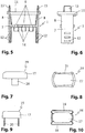
- said support comprises a horizontal holding plate (7) extending between two vertical uprights (8) and provided with a plurality of orifices (9) extending through the holding plate (7). ), said orifices (9) being adapted to receive tools such as a drill, a dental tenon, a reamer, etc ... and a base (10) extending parallel to the holding plate (7) and having a horizontal bearing surface facing the holding plate (7) and on which the distal end of the tool is intended to rest, said base (10) being movable relative to the holding plate (7) of such that the bearing surface is placed at a variable distance from the holding plate (7).
- the holding plate (7) has two rows of three orifices (9); however, it goes without saying that said holding plate (7) may include any number of orifices (9) without departing from the scope of the invention.
- the support (1) comprises a rectangular arch (11) integral with the upper end of the vertical uprights (8), said hoop (11) extending horizontally, parallel to the holding plate (7) which extends between the uprights (8) from the middle portion of said uprights (8), said uprights (8) having a decreasing thickness from the upper wall of the holding plate (7) to their upper ends.
- the inner wall of the uprights (8) flares outwardly from the holding plate (8) for easier grasping tools.
- the uprights (8) have a substantially rectangular shape whose width is less than the width of the holding plate (7), said holding plate (7) having a width less than that of the rectangular arch (11).
- Said vertical uprights (8) comprise, below the holding plate (7), at least one pair of lumens (12), said slots (12) being arranged facing one another.
- the vertical uprights (8) comprise three pairs of lumens (12) arranged opposite one another, said pairs of lumens (12) being evenly spaced between the bottom wall of the plate. holding (7) and the lower ends of the uprights (8).
- the amounts may include any number of lights (12) regularly spaced or not without departing from the scope of the invention.
- Said slots (12) are adapted to receive lugs (13) protruding from two opposite edges of the base (10).
- Said base (10) has a substantially rectangular shape whose length is substantially equal to the distance between the two vertical uprights (8) and whose width is substantially equal to the width of said uprights (8).
- Said lights (12) have a rectangular shape and the lugs (13) of the base (10) have a substantially parallelepiped shape.
- the lugs (13) of each base (10) have a height less than the thickness of the base (10) and are flush with one of the faces of said base (10).
- the lugs (13) of the base (10) may have any shape and that the lights (12) may have a shape complementary to said lugs (13) without departing from the scope of the invention.
- said holding plate (7) has on its bottom wall cylindrical bores (14) extending coaxially to the orifices (9) of said holding plate (7).
- the support according to the invention comprises two vertical tabs (15), forming gripping members, extending above the rectangular arch (11) in the extension of the vertical uprights (8).
- These vertical tabs (15) make it possible to grip the support between the thumb and forefinger without touching the tools positioned on said support, thus avoiding any contamination.
- the support comprises a first cover (16) comprising a cap (17) substantially parallelepiped whose lower edge is adapted to bear on the rectangular arch (11) and two opposite walls (18) adapted to extend between said hoop rectangular (11) and vertical uprights (8), to the lower ends of said uprights (8).
- the support comprises a second cover (19) comprising a cap (17) substantially parallelepiped whose lower edge is adapted to bear on the rectangular arch (11) and whose longitudinal edges are provided with fixing lugs (20) suitable to bear on the inner edge of the rectangular arch (11) to maintain said lid (19).
- the longitudinal walls of the cap (17) of the second cover (19) advantageously have a recess (21) to facilitate the gripping of said cover (19). This second cover helps preserve the tools
- the base (3) shown on them comprises a web (22) horizontal and two lateral wings (23,24) extending from the core (22) perpendicular thereto, facing one another .
- the soul (22) and the lateral wings (23,24) define an interior space.
- the base (3) can also be completed with a closure plate (4) appropriately secured to the side wings (23,24), opposite the core (22), to close the interior space of the base (3).
- the core (22) has an inner surface facing the inner space and an opposite outer surface.
- the core (22) is provided with openings (5) for communicating the interior space of the base (3) with the outside. Said openings (5) are adapted to each receive one of the supports 1.
- Each of the openings (5) is delimited by a peripheral shoulder (25) having a thickness and a corresponding contour substantially to those of the rectangular arch (11).
- each of the openings (5) is further provided with a rim (26) projecting from the peripheral edge.
- the side wings (23,24) also each have an inner surface facing the inner space and an opposite outer surface.
- Said side walls (23,24) are provided with securing members to allow the bases (3) of two identical housings to be secured.
- the securing members of each of the side walls (23,24) comprise a hook (27) and two stops (28) aligned in the longitudinal direction, projecting in the transverse direction on the outer surface, openings (29). aligned in the longitudinal direction.
- the hook (27) and the stops (28) of one (23), first, side wings (23,24) are placed near a lower edge of the first side wall (23), the openings ( 29) being placed near an upper edge of the first side wall (23).
- the hook (27) and the stops (28) of the other (24), second, side wings are placed near an upper edge of the second side wall (24), the openings (29) being placed near a lower edge of the second side wall (24).
- the hook (27) and the abutments (28) of the first side wall (23) of one of the bases (3) can engage in the openings (29) of the second side wall (24). from the other base (3).
- the inner surface of the side walls (23,24) may be provided with rods (30) extending in the vertical direction and arranged to enhance the holding and the contact of the hook (27) and stops (28). ) in the openings (29).
- first cover (16) and / or the second cover (19) and / or the cover (6) may advantageously be obtained in a transparent or translucent plastic material in order to allow visualization of the tools positioned on the supports.
- the support (1) and more particularly the holding plate (7) and the uprights (8), can be obtained in a plastic material dyed in the mass so that said supports (2) have the same color than the colored ring of the tools placed on said support (2).
- the colored ring of strawberries for example, is a standard indication according to the ISO standard of the type of diamond grain size of the milling cutter. Thus, a practitioner can find the tool he needs more easily and quickly.
- Said plastics are preferably sterilizable plastics well known to those skilled in the art.
Landscapes
- Health & Medical Sciences (AREA)
- Life Sciences & Earth Sciences (AREA)
- Surgery (AREA)
- Veterinary Medicine (AREA)
- Public Health (AREA)
- Animal Behavior & Ethology (AREA)
- General Health & Medical Sciences (AREA)
- Heart & Thoracic Surgery (AREA)
- Nuclear Medicine, Radiotherapy & Molecular Imaging (AREA)
- Engineering & Computer Science (AREA)
- Biomedical Technology (AREA)
- Medical Informatics (AREA)
- Molecular Biology (AREA)
- Dentistry (AREA)
- Oral & Maxillofacial Surgery (AREA)
- Epidemiology (AREA)
- Dental Tools And Instruments Or Auxiliary Dental Instruments (AREA)
Claims (13)
- Träger, um mindestens ein Werkzeug zu halten, insbesondere ein chirurgisches Werkzeug, insbesondere ein zahnchirurgisches Werkzeug, wobei das Werkzeug eine Länge zwischen einem proximalen Ende und einem distalen Ende aufweist, wobei der Träger mindestens eine horizontale Halteplatte (7) umfasst, die sich zwischen zwei vertikalen Säulen (8) erstreckt, und versehen mit mindestens einer Öffnung (9), die sich quer über die Halteplatte (7) erstreckt, wobei die Öffnung (9) ausgelegt ist, um das Werkzeug aufzunehmen, und einen Sockel (10), der sich parallel zur Halteplatte (7) erstreckt und eine horizontale Auflagefläche gegenüber der Halteplatte (7) aufweist, und auf der das distale Ende des Werkzeugs lagern soll, wobei der Sockel (10) mit Bezug auf die Halteplatte (7) derart verschoben werden kann, dass die Auflagefläche in einer variablen Distanz mit Bezug auf die Halteplatte (7) angeordnet ist, dadurch gekennzeichnet, dass er einen rechtwinkligen Bogen (11) umfasst, der mit dem oberen Ende der vertikalen Säulen (8) einstückig ist, wobei sich der Bogen (11) horizontal erstreckt, parallel zur Halteplatte (7), die sich zwischen den vertikalen Säulen (8) vom mittleren Teil der Säulen (8) erstreckt, wobei die vertikalen Säulen (8) eine abnehmende Dicke von der oberen Wand der Halteplatte (7) bis zu ihren oberen Enden aufweisen.
- Träger nach dem vorhergehenden Anspruch, dadurch gekennzeichnet, dass die vertikalen Säulen (8) eine im Wesentlichen rechtwinklige Form aufweisen, deren Breite geringer als die Breite der Halteplatte (7) ist, wobei die Halteplatte (7) eine Breite aufweist, die geringer als diejenige des rechtwinkligen Bogens (11) ist.
- Träger nach einem beliebigen der Ansprüche 1 oder 2, dadurch gekennzeichnet, dass die vertikalen Säulen (8) unter der Halteplatte (7) mindestens ein Paar Löcher (12) umfassen, wobei die Löcher (12) einander gegenüber liegend angebracht sind, dazu ausgelegt, Zapfen (13) aufzunehmen, die von zwei einander gegenüber liegenden Rändern des Sockels (10) hervorspringen.
- Träger nach Anspruch 3, dadurch gekennzeichnet, dass die Zapfen (13) jedes Sockels (10) eine Höhe aufweisen, die geringer als die Dicke des Sockels (10) ist und mit einem der Seiten des Sockels (10) bündig sind.
- Träger nach einem beliebigen der Ansprüche 3 oder 4, dadurch gekennzeichnet, dass die vertikalen Säulen (8) drei Paar Löcher (12) umfassen, die einander gegenüber liegend angebracht sind.
- Träger nach einem beliebigen der Ansprüche 3 bis 5, dadurch gekennzeichnet, dass die Löcher (12) regelmäßig zwischen der unteren Wand der Halteplatte (7) und den unteren Enden der vertikalen Säulen (8) verteilt sind.
- Träger nach einem beliebigen der Ansprüche 3 bis 6, dadurch gekennzeichnet, dass der Sockel (10) eine im Wesentlichen rechtwinklige Form aufweist, deren Länge im Wesentlichen gleich dem Abstand ist, der die zwei vertikalen Säulen (8) trennt, und deren Breite im Wesentlichen gleich der Breite der Säulen (8) ist.
- Träger nach einem beliebigen der Ansprüche 3 bis 7, dadurch gekennzeichnet, dass die Löcher (12) eine rechtwinklige Form aufweisen und die Zapfen (13) des Sockels (10) eine im Wesentlichen parallelepipede Form aufweisen.
- Träger nach einem beliebigen der Ansprüche 1 bis 8, dadurch gekennzeichnet, dass die Halteplatte (7) auf ihrer unteren Wand Bohrungen (14) umfasst, die sich koaxial zu den Öffnungen (9) der Halteplatte (7) erstrecken.
- Träger nach einem beliebigen der Ansprüche 1 bis 9, dadurch gekennzeichnet, dass er zwei vertikale Füße (15) umfasst, die Greiforgane bilden, die sich über dem rechtwinkligen Bogen (11) in der Verlängerung der vertikalen Säulen (8) erstrecken.
- Träger nach einem beliebigen der Ansprüche 1 bis 10, dadurch gekennzeichnet, dass er einen ersten Deckel (16) umfasst, der eine im Wesentlichen parallelepipede Abdeckung (17) aufweist, deren unterer Rand ausgelegt ist, um auf dem rechtwinkligen Bogen (11) aufzuliegen, und zwei gegenüber liegende Wände (18), die ausgelegt sind, um sich zwischen dem rechtwinkligen Bogen (11) und den vertikalen Säulen (8) bis zu den unteren Enden der vertikalen Säulen (8) zu erstrecken.
- Träger nach einem beliebigen der Ansprüche 1 bis 10, dadurch gekennzeichnet, dass er einen zweiten Deckel (19) umfasst, der eine im Wesentlichen parallelepipede Abdeckung (17) umfasst, deren unterer Rand Längsränder mit Befestigungsfüßen (20) ausgestattet sind, die ausgelegt sind, um auf dem Innenrand des rechtwinkligen Bogens (11) aufzuliegen, um den Halt des Deckels (19) sicherzustellen.
- Träger nach Anspruch 12, dadurch gekennzeichnet, dass die Längswände der Abdeckung (17) des zweiten Deckels (19) einen Hohlraum (21) darstellen, um das Greifen Deckels (19) zu erleichtern.
Applications Claiming Priority (1)
| Application Number | Priority Date | Filing Date | Title |
|---|---|---|---|
| FR1451857A FR3018186B1 (fr) | 2014-03-07 | 2014-03-07 | Perfectionnement a un support pour maintenir un outil |
Related Parent Applications (1)
| Application Number | Title | Priority Date | Filing Date |
|---|---|---|---|
| FR1451857 Previously-Filed-Application | 2014-03-07 |
Publications (2)
| Publication Number | Publication Date |
|---|---|
| EP2915501A1 EP2915501A1 (de) | 2015-09-09 |
| EP2915501B1 true EP2915501B1 (de) | 2017-08-16 |
Family
ID=50729679
Family Applications (1)
| Application Number | Title | Priority Date | Filing Date |
|---|---|---|---|
| EP15158101.4A Active EP2915501B1 (de) | 2014-03-07 | 2015-03-06 | Halterung zur Aufnahme eines Werkzeugs |
Country Status (2)
| Country | Link |
|---|---|
| EP (1) | EP2915501B1 (de) |
| FR (1) | FR3018186B1 (de) |
Families Citing this family (1)
| Publication number | Priority date | Publication date | Assignee | Title |
|---|---|---|---|---|
| CN111110360B (zh) * | 2019-12-24 | 2020-12-22 | 江苏福维健康科技有限公司 | 一种手术器械台器械摆放架 |
Family Cites Families (5)
| Publication number | Priority date | Publication date | Assignee | Title |
|---|---|---|---|---|
| US5829590A (en) | 1996-05-08 | 1998-11-03 | Klein; Philip B. | Box for the storage and sterilization of plural dental posts and associated drill bits |
| US20070119871A1 (en) * | 2005-11-07 | 2007-05-31 | Garcia Saddy R | Fastener cartridge |
| FR2946521B1 (fr) | 2009-06-16 | 2012-08-10 | Eric Lachaud | Systeme de rangement d'instruments. |
| US8641984B2 (en) * | 2009-11-16 | 2014-02-04 | Q-Case, Inc. | Surgical instrument tray system |
| FR2968925B1 (fr) * | 2010-12-15 | 2013-11-01 | Exotec Dentaire | Support pour maintenir au moins un outil, boitier comprenant un tel support et ensemble comprenant un tel boitier |
-
2014
- 2014-03-07 FR FR1451857A patent/FR3018186B1/fr active Active
-
2015
- 2015-03-06 EP EP15158101.4A patent/EP2915501B1/de active Active
Non-Patent Citations (1)
| Title |
|---|
| None * |
Also Published As
| Publication number | Publication date |
|---|---|
| EP2915501A1 (de) | 2015-09-09 |
| FR3018186A1 (fr) | 2015-09-11 |
| FR3018186B1 (fr) | 2016-06-10 |
Similar Documents
| Publication | Publication Date | Title |
|---|---|---|
| EP1988838B1 (de) | Zwischenwirbelimplantat | |
| FR2916956A1 (fr) | Cage intersomatique,prothese intervertebrale,dispositif d'ancrage et instrumentation d'implantation | |
| EP0704191A1 (de) | Chirurgische Anordnung mit einem Fräser und einem Halter hierfür | |
| WO2004096073A2 (fr) | Emballage pour la presentation individuelle d'au moins une vis | |
| EP1487371A1 (de) | Verpackungs- sowie darstellungsgehäuse für osteosyntheseimplantat, schutzanordnung und präsentationsbehälter mit solch einem gehäuse | |
| EP0782840B1 (de) | Fräse mit einem rohrförmigen Teil | |
| EP2915501B1 (de) | Halterung zur Aufnahme eines Werkzeugs | |
| EP2404537A1 (de) | Küchengerät mit herunterklappbarem Grifforgan | |
| EP3968891B1 (de) | Vorrichtung zum halten und freigeben eines objekts und zugehörige verfahren | |
| CA2546871C (fr) | Fraise chirurgicale | |
| EP1591085A1 (de) | Kit zur Zubereitung eines Knochenfüllungsgemisch, Patrone speziell angepasst an diesem Kit und Implantationskoffer mit dem Kit | |
| WO2001056495A1 (fr) | Clef de descellement | |
| WO1994001055A1 (fr) | Plateau et plateau/cassette modulaire pour la sterilisation de l'instrumentation dentaire | |
| CA3005415A1 (fr) | Dispositif d'ejection d'un bouchon hors d'un tire-bouchon et tire-bouchon equipe d'un tel dispositif d'ejection | |
| WO2007073606A1 (fr) | Fraise chirurgicale et lames pour une telle fraise | |
| EP0709133A1 (de) | Einwegständer für Proberöhrchen | |
| EP2490616B1 (de) | Vorrichtung zur lagerung und ausgabe von zahnärztlichen teilen | |
| WO1997039701A1 (fr) | Emballage pour le pliage des implants intraoculaires | |
| EP0192571B1 (de) | Probenhalter für Zentrifuge und Verfahren zu seiner Herstellung | |
| EP0263011B1 (de) | Halter für zahnärztliche Schleif- und Fräswerkzeuge | |
| FR2968925A1 (fr) | Support pour maintenir au moins un outil, boitier comprenant un tel support et ensemble comprenant un tel boitier | |
| FR3141852A1 (fr) | Punch de découpe partitionnée d’un greffon cornéal et porte-lame correspondant | |
| BE1021728B1 (fr) | Receptacle pour collecter un essaim d'abeilles | |
| FR2638955A1 (fr) | Presentoir mobile, notamment de flacons | |
| EP1443481B1 (de) | Schaugestell für Haarsträhne |
Legal Events
| Date | Code | Title | Description |
|---|---|---|---|
| PUAI | Public reference made under article 153(3) epc to a published international application that has entered the european phase |
Free format text: ORIGINAL CODE: 0009012 |
|
| AK | Designated contracting states |
Kind code of ref document: A1 Designated state(s): AL AT BE BG CH CY CZ DE DK EE ES FI FR GB GR HR HU IE IS IT LI LT LU LV MC MK MT NL NO PL PT RO RS SE SI SK SM TR |
|
| AX | Request for extension of the european patent |
Extension state: BA ME |
|
| 17P | Request for examination filed |
Effective date: 20160304 |
|
| RBV | Designated contracting states (corrected) |
Designated state(s): AL AT BE BG CH CY CZ DE DK EE ES FI FR GB GR HR HU IE IS IT LI LT LU LV MC MK MT NL NO PL PT RO RS SE SI SK SM TR |
|
| REG | Reference to a national code |
Ref country code: DE Ref legal event code: R079 Ref document number: 602015004082 Country of ref document: DE Free format text: PREVIOUS MAIN CLASS: A61B0019020000 Ipc: A61B0050200000 |
|
| GRAP | Despatch of communication of intention to grant a patent |
Free format text: ORIGINAL CODE: EPIDOSNIGR1 |
|
| RIC1 | Information provided on ipc code assigned before grant |
Ipc: A61B 50/22 20160101ALI20170223BHEP Ipc: A61B 50/20 20160101AFI20170223BHEP Ipc: A61C 3/04 20060101ALN20170223BHEP Ipc: A61C 19/02 20060101ALI20170223BHEP |
|
| INTG | Intention to grant announced |
Effective date: 20170328 |
|
| RIN1 | Information on inventor provided before grant (corrected) |
Inventor name: BLOIS, ERIC |
|
| GRAS | Grant fee paid |
Free format text: ORIGINAL CODE: EPIDOSNIGR3 |
|
| GRAA | (expected) grant |
Free format text: ORIGINAL CODE: 0009210 |
|
| AK | Designated contracting states |
Kind code of ref document: B1 Designated state(s): AL AT BE BG CH CY CZ DE DK EE ES FI FR GB GR HR HU IE IS IT LI LT LU LV MC MK MT NL NO PL PT RO RS SE SI SK SM TR |
|
| REG | Reference to a national code |
Ref country code: GB Ref legal event code: FG4D Free format text: NOT ENGLISH |
|
| REG | Reference to a national code |
Ref country code: CH Ref legal event code: EP |
|
| REG | Reference to a national code |
Ref country code: IE Ref legal event code: FG4D Free format text: LANGUAGE OF EP DOCUMENT: FRENCH |
|
| REG | Reference to a national code |
Ref country code: AT Ref legal event code: REF Ref document number: 918330 Country of ref document: AT Kind code of ref document: T Effective date: 20170915 |
|
| REG | Reference to a national code |
Ref country code: DE Ref legal event code: R096 Ref document number: 602015004082 Country of ref document: DE |
|
| REG | Reference to a national code |
Ref country code: NL Ref legal event code: MP Effective date: 20170816 |
|
| REG | Reference to a national code |
Ref country code: LT Ref legal event code: MG4D |
|
| REG | Reference to a national code |
Ref country code: AT Ref legal event code: MK05 Ref document number: 918330 Country of ref document: AT Kind code of ref document: T Effective date: 20170816 |
|
| PG25 | Lapsed in a contracting state [announced via postgrant information from national office to epo] |
Ref country code: NL Free format text: LAPSE BECAUSE OF FAILURE TO SUBMIT A TRANSLATION OF THE DESCRIPTION OR TO PAY THE FEE WITHIN THE PRESCRIBED TIME-LIMIT Effective date: 20170816 Ref country code: SE Free format text: LAPSE BECAUSE OF FAILURE TO SUBMIT A TRANSLATION OF THE DESCRIPTION OR TO PAY THE FEE WITHIN THE PRESCRIBED TIME-LIMIT Effective date: 20170816 Ref country code: FI Free format text: LAPSE BECAUSE OF FAILURE TO SUBMIT A TRANSLATION OF THE DESCRIPTION OR TO PAY THE FEE WITHIN THE PRESCRIBED TIME-LIMIT Effective date: 20170816 Ref country code: NO Free format text: LAPSE BECAUSE OF FAILURE TO SUBMIT A TRANSLATION OF THE DESCRIPTION OR TO PAY THE FEE WITHIN THE PRESCRIBED TIME-LIMIT Effective date: 20171116 Ref country code: AT Free format text: LAPSE BECAUSE OF FAILURE TO SUBMIT A TRANSLATION OF THE DESCRIPTION OR TO PAY THE FEE WITHIN THE PRESCRIBED TIME-LIMIT Effective date: 20170816 Ref country code: LT Free format text: LAPSE BECAUSE OF FAILURE TO SUBMIT A TRANSLATION OF THE DESCRIPTION OR TO PAY THE FEE WITHIN THE PRESCRIBED TIME-LIMIT Effective date: 20170816 |
|
| PG25 | Lapsed in a contracting state [announced via postgrant information from national office to epo] |
Ref country code: PL Free format text: LAPSE BECAUSE OF FAILURE TO SUBMIT A TRANSLATION OF THE DESCRIPTION OR TO PAY THE FEE WITHIN THE PRESCRIBED TIME-LIMIT Effective date: 20170816 Ref country code: RS Free format text: LAPSE BECAUSE OF FAILURE TO SUBMIT A TRANSLATION OF THE DESCRIPTION OR TO PAY THE FEE WITHIN THE PRESCRIBED TIME-LIMIT Effective date: 20170816 Ref country code: LV Free format text: LAPSE BECAUSE OF FAILURE TO SUBMIT A TRANSLATION OF THE DESCRIPTION OR TO PAY THE FEE WITHIN THE PRESCRIBED TIME-LIMIT Effective date: 20170816 Ref country code: IS Free format text: LAPSE BECAUSE OF FAILURE TO SUBMIT A TRANSLATION OF THE DESCRIPTION OR TO PAY THE FEE WITHIN THE PRESCRIBED TIME-LIMIT Effective date: 20171216 Ref country code: ES Free format text: LAPSE BECAUSE OF FAILURE TO SUBMIT A TRANSLATION OF THE DESCRIPTION OR TO PAY THE FEE WITHIN THE PRESCRIBED TIME-LIMIT Effective date: 20170816 Ref country code: GR Free format text: LAPSE BECAUSE OF FAILURE TO SUBMIT A TRANSLATION OF THE DESCRIPTION OR TO PAY THE FEE WITHIN THE PRESCRIBED TIME-LIMIT Effective date: 20171117 Ref country code: BG Free format text: LAPSE BECAUSE OF FAILURE TO SUBMIT A TRANSLATION OF THE DESCRIPTION OR TO PAY THE FEE WITHIN THE PRESCRIBED TIME-LIMIT Effective date: 20171116 |
|
| REG | Reference to a national code |
Ref country code: FR Ref legal event code: PLFP Year of fee payment: 4 |
|
| PG25 | Lapsed in a contracting state [announced via postgrant information from national office to epo] |
Ref country code: CZ Free format text: LAPSE BECAUSE OF FAILURE TO SUBMIT A TRANSLATION OF THE DESCRIPTION OR TO PAY THE FEE WITHIN THE PRESCRIBED TIME-LIMIT Effective date: 20170816 Ref country code: RO Free format text: LAPSE BECAUSE OF FAILURE TO SUBMIT A TRANSLATION OF THE DESCRIPTION OR TO PAY THE FEE WITHIN THE PRESCRIBED TIME-LIMIT Effective date: 20170816 Ref country code: DK Free format text: LAPSE BECAUSE OF FAILURE TO SUBMIT A TRANSLATION OF THE DESCRIPTION OR TO PAY THE FEE WITHIN THE PRESCRIBED TIME-LIMIT Effective date: 20170816 |
|
| REG | Reference to a national code |
Ref country code: DE Ref legal event code: R097 Ref document number: 602015004082 Country of ref document: DE |
|
| PG25 | Lapsed in a contracting state [announced via postgrant information from national office to epo] |
Ref country code: EE Free format text: LAPSE BECAUSE OF FAILURE TO SUBMIT A TRANSLATION OF THE DESCRIPTION OR TO PAY THE FEE WITHIN THE PRESCRIBED TIME-LIMIT Effective date: 20170816 Ref country code: IT Free format text: LAPSE BECAUSE OF FAILURE TO SUBMIT A TRANSLATION OF THE DESCRIPTION OR TO PAY THE FEE WITHIN THE PRESCRIBED TIME-LIMIT Effective date: 20170816 Ref country code: SK Free format text: LAPSE BECAUSE OF FAILURE TO SUBMIT A TRANSLATION OF THE DESCRIPTION OR TO PAY THE FEE WITHIN THE PRESCRIBED TIME-LIMIT Effective date: 20170816 Ref country code: SM Free format text: LAPSE BECAUSE OF FAILURE TO SUBMIT A TRANSLATION OF THE DESCRIPTION OR TO PAY THE FEE WITHIN THE PRESCRIBED TIME-LIMIT Effective date: 20170816 |
|
| PLBE | No opposition filed within time limit |
Free format text: ORIGINAL CODE: 0009261 |
|
| STAA | Information on the status of an ep patent application or granted ep patent |
Free format text: STATUS: NO OPPOSITION FILED WITHIN TIME LIMIT |
|
| 26N | No opposition filed |
Effective date: 20180517 |
|
| PG25 | Lapsed in a contracting state [announced via postgrant information from national office to epo] |
Ref country code: SI Free format text: LAPSE BECAUSE OF FAILURE TO SUBMIT A TRANSLATION OF THE DESCRIPTION OR TO PAY THE FEE WITHIN THE PRESCRIBED TIME-LIMIT Effective date: 20170816 |
|
| PG25 | Lapsed in a contracting state [announced via postgrant information from national office to epo] |
Ref country code: MT Free format text: LAPSE BECAUSE OF FAILURE TO SUBMIT A TRANSLATION OF THE DESCRIPTION OR TO PAY THE FEE WITHIN THE PRESCRIBED TIME-LIMIT Effective date: 20170816 |
|
| REG | Reference to a national code |
Ref country code: CH Ref legal event code: PL |
|
| PG25 | Lapsed in a contracting state [announced via postgrant information from national office to epo] |
Ref country code: MC Free format text: LAPSE BECAUSE OF FAILURE TO SUBMIT A TRANSLATION OF THE DESCRIPTION OR TO PAY THE FEE WITHIN THE PRESCRIBED TIME-LIMIT Effective date: 20170816 |
|
| REG | Reference to a national code |
Ref country code: IE Ref legal event code: MM4A |
|
| PG25 | Lapsed in a contracting state [announced via postgrant information from national office to epo] |
Ref country code: LU Free format text: LAPSE BECAUSE OF NON-PAYMENT OF DUE FEES Effective date: 20180306 |
|
| PG25 | Lapsed in a contracting state [announced via postgrant information from national office to epo] |
Ref country code: IE Free format text: LAPSE BECAUSE OF NON-PAYMENT OF DUE FEES Effective date: 20180306 |
|
| PG25 | Lapsed in a contracting state [announced via postgrant information from national office to epo] |
Ref country code: LI Free format text: LAPSE BECAUSE OF NON-PAYMENT OF DUE FEES Effective date: 20180331 Ref country code: CH Free format text: LAPSE BECAUSE OF NON-PAYMENT OF DUE FEES Effective date: 20180331 |
|
| PG25 | Lapsed in a contracting state [announced via postgrant information from national office to epo] |
Ref country code: TR Free format text: LAPSE BECAUSE OF FAILURE TO SUBMIT A TRANSLATION OF THE DESCRIPTION OR TO PAY THE FEE WITHIN THE PRESCRIBED TIME-LIMIT Effective date: 20170816 |
|
| PG25 | Lapsed in a contracting state [announced via postgrant information from national office to epo] |
Ref country code: PT Free format text: LAPSE BECAUSE OF FAILURE TO SUBMIT A TRANSLATION OF THE DESCRIPTION OR TO PAY THE FEE WITHIN THE PRESCRIBED TIME-LIMIT Effective date: 20170816 |
|
| PG25 | Lapsed in a contracting state [announced via postgrant information from national office to epo] |
Ref country code: CY Free format text: LAPSE BECAUSE OF FAILURE TO SUBMIT A TRANSLATION OF THE DESCRIPTION OR TO PAY THE FEE WITHIN THE PRESCRIBED TIME-LIMIT Effective date: 20170816 Ref country code: HU Free format text: LAPSE BECAUSE OF FAILURE TO SUBMIT A TRANSLATION OF THE DESCRIPTION OR TO PAY THE FEE WITHIN THE PRESCRIBED TIME-LIMIT; INVALID AB INITIO Effective date: 20150306 Ref country code: MK Free format text: LAPSE BECAUSE OF NON-PAYMENT OF DUE FEES Effective date: 20170816 Ref country code: HR Free format text: LAPSE BECAUSE OF FAILURE TO SUBMIT A TRANSLATION OF THE DESCRIPTION OR TO PAY THE FEE WITHIN THE PRESCRIBED TIME-LIMIT Effective date: 20170816 |
|
| PG25 | Lapsed in a contracting state [announced via postgrant information from national office to epo] |
Ref country code: AL Free format text: LAPSE BECAUSE OF FAILURE TO SUBMIT A TRANSLATION OF THE DESCRIPTION OR TO PAY THE FEE WITHIN THE PRESCRIBED TIME-LIMIT Effective date: 20170816 |
|
| PGFP | Annual fee paid to national office [announced via postgrant information from national office to epo] |
Ref country code: GB Payment date: 20260213 Year of fee payment: 12 |
|
| PGFP | Annual fee paid to national office [announced via postgrant information from national office to epo] |
Ref country code: DE Payment date: 20260216 Year of fee payment: 12 |
|
| PGFP | Annual fee paid to national office [announced via postgrant information from national office to epo] |
Ref country code: BE Payment date: 20260323 Year of fee payment: 12 |
|
| PGFP | Annual fee paid to national office [announced via postgrant information from national office to epo] |
Ref country code: FR Payment date: 20260213 Year of fee payment: 12 |