EP2915571B1 - Einstellbare rahmenbaugruppen, verfahren zur montage einer filtervorrichtung und filtervorrichtungen - Google Patents
Einstellbare rahmenbaugruppen, verfahren zur montage einer filtervorrichtung und filtervorrichtungen Download PDFInfo
- Publication number
- EP2915571B1 EP2915571B1 EP15156705.4A EP15156705A EP2915571B1 EP 2915571 B1 EP2915571 B1 EP 2915571B1 EP 15156705 A EP15156705 A EP 15156705A EP 2915571 B1 EP2915571 B1 EP 2915571B1
- Authority
- EP
- European Patent Office
- Prior art keywords
- adjustable frame
- piping system
- filter modules
- frame structure
- base arrangement
- Prior art date
- Legal status (The legal status is an assumption and is not a legal conclusion. Google has not performed a legal analysis and makes no representation as to the accuracy of the status listed.)
- Active
Links
- 238000000034 method Methods 0.000 title claims description 13
- 238000000429 assembly Methods 0.000 title description 6
- 230000000712 assembly Effects 0.000 title description 6
- 239000012530 fluid Substances 0.000 claims description 38
- 230000007246 mechanism Effects 0.000 claims description 10
- 239000000706 filtrate Substances 0.000 description 20
- 239000000463 material Substances 0.000 description 4
- 238000004140 cleaning Methods 0.000 description 3
- 238000001914 filtration Methods 0.000 description 3
- 239000002184 metal Substances 0.000 description 3
- 230000005465 channeling Effects 0.000 description 2
- -1 e.g. Substances 0.000 description 2
- 239000012465 retentate Substances 0.000 description 2
- 229910000831 Steel Inorganic materials 0.000 description 1
- 238000011001 backwashing Methods 0.000 description 1
- 239000012141 concentrate Substances 0.000 description 1
- 238000009295 crossflow filtration Methods 0.000 description 1
- 238000007599 discharging Methods 0.000 description 1
- 239000012510 hollow fiber Substances 0.000 description 1
- 239000007788 liquid Substances 0.000 description 1
- 239000012528 membrane Substances 0.000 description 1
- 239000012466 permeate Substances 0.000 description 1
- 238000005201 scrubbing Methods 0.000 description 1
- 239000010959 steel Substances 0.000 description 1
- 239000000126 substance Substances 0.000 description 1
Images




Classifications
-
- F—MECHANICAL ENGINEERING; LIGHTING; HEATING; WEAPONS; BLASTING
- F16—ENGINEERING ELEMENTS AND UNITS; GENERAL MEASURES FOR PRODUCING AND MAINTAINING EFFECTIVE FUNCTIONING OF MACHINES OR INSTALLATIONS; THERMAL INSULATION IN GENERAL
- F16M—FRAMES, CASINGS OR BEDS OF ENGINES, MACHINES OR APPARATUS, NOT SPECIFIC TO ENGINES, MACHINES OR APPARATUS PROVIDED FOR ELSEWHERE; STANDS; SUPPORTS
- F16M1/00—Frames or casings of engines, machines or apparatus; Frames serving as machinery beds
-
- B—PERFORMING OPERATIONS; TRANSPORTING
- B01—PHYSICAL OR CHEMICAL PROCESSES OR APPARATUS IN GENERAL
- B01D—SEPARATION
- B01D29/00—Filters with filtering elements stationary during filtration, e.g. pressure or suction filters, not covered by groups B01D24/00 - B01D27/00; Filtering elements therefor
- B01D29/50—Filters with filtering elements stationary during filtration, e.g. pressure or suction filters, not covered by groups B01D24/00 - B01D27/00; Filtering elements therefor with multiple filtering elements, characterised by their mutual disposition
- B01D29/52—Filters with filtering elements stationary during filtration, e.g. pressure or suction filters, not covered by groups B01D24/00 - B01D27/00; Filtering elements therefor with multiple filtering elements, characterised by their mutual disposition in parallel connection
-
- B—PERFORMING OPERATIONS; TRANSPORTING
- B01—PHYSICAL OR CHEMICAL PROCESSES OR APPARATUS IN GENERAL
- B01D—SEPARATION
- B01D35/00—Filtering devices having features not specifically covered by groups B01D24/00 - B01D33/00, or for applications not specifically covered by groups B01D24/00 - B01D33/00; Auxiliary devices for filtration; Filter housing constructions
- B01D35/30—Filter housing constructions
- B01D35/301—Constructions of two or more housings
-
- B—PERFORMING OPERATIONS; TRANSPORTING
- B01—PHYSICAL OR CHEMICAL PROCESSES OR APPARATUS IN GENERAL
- B01D—SEPARATION
- B01D35/00—Filtering devices having features not specifically covered by groups B01D24/00 - B01D33/00, or for applications not specifically covered by groups B01D24/00 - B01D33/00; Auxiliary devices for filtration; Filter housing constructions
- B01D35/30—Filter housing constructions
- B01D35/301—Constructions of two or more housings
- B01D35/303—Constructions of two or more housings the housings being modular, e.g. standardised
-
- B—PERFORMING OPERATIONS; TRANSPORTING
- B01—PHYSICAL OR CHEMICAL PROCESSES OR APPARATUS IN GENERAL
- B01D—SEPARATION
- B01D35/00—Filtering devices having features not specifically covered by groups B01D24/00 - B01D33/00, or for applications not specifically covered by groups B01D24/00 - B01D33/00; Auxiliary devices for filtration; Filter housing constructions
- B01D35/30—Filter housing constructions
- B01D35/306—Filter mounting adapter
-
- B—PERFORMING OPERATIONS; TRANSPORTING
- B01—PHYSICAL OR CHEMICAL PROCESSES OR APPARATUS IN GENERAL
- B01D—SEPARATION
- B01D61/00—Processes of separation using semi-permeable membranes, e.g. dialysis, osmosis or ultrafiltration; Apparatus, accessories or auxiliary operations specially adapted therefor
-
- F—MECHANICAL ENGINEERING; LIGHTING; HEATING; WEAPONS; BLASTING
- F16—ENGINEERING ELEMENTS AND UNITS; GENERAL MEASURES FOR PRODUCING AND MAINTAINING EFFECTIVE FUNCTIONING OF MACHINES OR INSTALLATIONS; THERMAL INSULATION IN GENERAL
- F16L—PIPES; JOINTS OR FITTINGS FOR PIPES; SUPPORTS FOR PIPES, CABLES OR PROTECTIVE TUBING; MEANS FOR THERMAL INSULATION IN GENERAL
- F16L3/00—Supports for pipes, cables or protective tubing, e.g. hangers, holders, clamps, cleats, clips, brackets
- F16L3/22—Supports for pipes, cables or protective tubing, e.g. hangers, holders, clamps, cleats, clips, brackets specially adapted for supporting a number of parallel pipes at intervals
- F16L3/221—Supports for pipes, cables or protective tubing, e.g. hangers, holders, clamps, cleats, clips, brackets specially adapted for supporting a number of parallel pipes at intervals having brackets connected together by means of a common support
-
- B—PERFORMING OPERATIONS; TRANSPORTING
- B01—PHYSICAL OR CHEMICAL PROCESSES OR APPARATUS IN GENERAL
- B01D—SEPARATION
- B01D2313/00—Details relating to membrane modules or apparatus
- B01D2313/06—External membrane module supporting or fixing means
-
- B—PERFORMING OPERATIONS; TRANSPORTING
- B01—PHYSICAL OR CHEMICAL PROCESSES OR APPARATUS IN GENERAL
- B01D—SEPARATION
- B01D2317/00—Membrane module arrangements within a plant or an apparatus
- B01D2317/04—Elements in parallel
-
- Y—GENERAL TAGGING OF NEW TECHNOLOGICAL DEVELOPMENTS; GENERAL TAGGING OF CROSS-SECTIONAL TECHNOLOGIES SPANNING OVER SEVERAL SECTIONS OF THE IPC; TECHNICAL SUBJECTS COVERED BY FORMER USPC CROSS-REFERENCE ART COLLECTIONS [XRACs] AND DIGESTS
- Y10—TECHNICAL SUBJECTS COVERED BY FORMER USPC
- Y10T—TECHNICAL SUBJECTS COVERED BY FORMER US CLASSIFICATION
- Y10T29/00—Metal working
- Y10T29/49—Method of mechanical manufacture
- Y10T29/49826—Assembling or joining
Definitions
- the present invention relates to adjustable frame assemblies, methods for assembling a filter apparatus, and filter apparatuses.
- US 2002/179517 A1 shows an adjustable frame for filters with lower base and upper base and an an adjustable frame structure.
- the adjustable frame assemblies embodying the invention comprise a lower base arrangement, an upper base arrangement, and an adjustable frame structure.
- the adjustable frame structure is connected between the lower and upper base arrangements and is moveable between a first position and a second position.
- the first position the lower and upper base arrangements are spaced a smaller first distance apart, providing a more compact and easily shippable frame assembly.
- the second position the lower and upper base arrangements are spaced a second greater distance apart.
- the second distance may correspond to the height of one or more filter modules, allowing the filter modules to be positioned on and supported by the frame assembly.
- Both the lower and upper base arrangements may include mounts for receiving and supporting an end of the filter modules.
- At least one of the lower and upper base arrangements may include a piping system for channeling fluid to and/or from an end of the filter modules.
- Methods for assembling a filter apparatus may comprise moving the adjustable frame structure from the first position to the second position.
- the adjustable frame structure is connected between the lower and upper base arrangements, and in the first position the lower and upper base arrangements are spaced a first smaller distance apart. In the second position the lower and upper base arrangements are spaced a second larger distance apart, e.g., a distance corresponding to the height of the filter modules.
- the methods for assembling a filter apparatus further comprise positioning opposite ends of the filter modules in mounts on the lower and upper base arrangements when the adjustable frame structure is in the second position and connecting a piping system on at least one of the lower and upper base arrangements to the filter modules.
- Filter apparatuses embodying the invention may comprise a frame assembly and two or more filter modules mounted to the frame assembly.
- the frame assembly may include lower and upper base arrangements and an adjustable frame structure.
- Each of the base arrangements may have two or more mounts, and at least one of the base arrangements may have a piping system.
- the adjustable frame structure has a first position in which the lower and upper base arrangements are spaced a first distance apart and a second position in which the lower and upper base arrangements are spaced a larger second distance apart, the adjustable frame structure being positioned in the second position.
- the filter modules may have opposite ends and a height corresponding to the second distance. The ends of the filter modules may be positioned in the mounts of the lower and upper base arrangements, and the piping system may be coupled to the filter modules to channel fluid to or from the filter modules.
- Adjustable frame assemblies embodying the invention may be configured in a wide variety of ways.
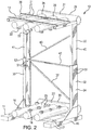
- An adjustable frame assembly 10 is shown in FIGS. 1 and 2 .
- the adjustable frame assembly 10 generally includes a lower base arrangement 11, an upper base arrangement 12, and an adjustable frame structure 13 connected between the lower and upper base arrangements 11, 12.
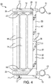
- the adjustable frame structure 13 is moveable between first and second positions. In the first position, the lower and upper base arrangements 11, 12 are spaced a smaller first distance apart, providing a more compact and easily shippable frame assembly 10. In the second position, the lower and upper base arrangements 11, 12 are spaced a larger second distance apart, allowing a plurality of filter modules 14 to be positioned on, and supported by, the frame assembly 10, as shown in FIGS. 4 and 5 .
- the adjustable frame structure may be arranged to move between the first and second positions in any of numerous ways. For example, the adjustable frame structure may move linearly, rotatively, or pivotally between the first and second positions.
- the lower base arrangement and the upper base arrangement may be configured in any of numerous ways.
- the lower base arrangement 11 may include a lower frame 15 and a plurality of lower mounts 16, as shown in FIGS. 1 and 2 .
- the lower frame 15 may have any of numerous shapes, e.g., a generally rectangular, planar shape, and may be fashioned by attaching lower frame elements 17 to one another, for example, by welds and/or fasteners such as bolts and nuts.
- the lower frame elements may be variously structured and may be fashioned from a polymeric material or a metal.
- the lower frame elements 17 may be steel channel elements welded to one another to form the lower frame 15.
- the lower mounts 16 may be attached to the lower frame 15, for example, by welds and/or fasteners, either directly or via the piping system.
- the lower mounts 16 may also be fashioned from a polymeric material or a metal and may be configured in any of numerous ways to position and support the lower ends of the filter modules 14.
- the upper base arrangement may be variously configured either similarly to or differently from the lower base arrangement.
- the upper base arrangement 12 may include both an upper frame 20 fashioned from upper frame elements 21 and a plurality of upper mounts 22 for positioning and supporting the upper ends of the filter modules 14, as shown in FIGS. 1 and 2 .
- the upper mounts 22 may be attached to the upper frame 20, for example, by welds or fasteners, either directly or via the piping system.
- the upper frame 20, the upper frame elements 21, and the upper mounts 21 of the upper base arrangement 12 may be similar to the lower frame 15, the lower frame elements 17, and the lower mounts 16 of the lower base arrangement 11, as previously described.
- At least one of the lower and upper base arrangements, or both, may further include a piping system for channeling fluid to or from the filter modules.
- the piping system may be attached only to the lower base arrangement, or only to the upper base arrangement, to supply and extract fluid from only one end of the filter modules.
- the piping system may include a lower piping system on the lower frame and an upper piping system on the upper frame.
- the piping system may include a lower piping system 23 connected to the lower frame 15 of the lower base arrangement 11 to channel fluid to or from the lower ends of the filter modules 14 and an upper piping system 24 connected to the upper frame 20 of the upper base arrangement 12 to channel fluid to or from the upper ends of the filter modules 14.
- the piping system may be configured in a myriad of ways depending, for example, on the type of filtration provided by the filter modules and/or the auxiliary functions provided with the filter modules, e.g., liquid forward- or back-washing or gas cross scrubbing or blowback.
- the piping systems may also vary depending on the flow arrangement through the filter modules, e.g., whether the filter modules are arranged in a parallel arrangement, a series arrangement, or some parallel-series combination.
- the piping system may include pipes for supplying unfiltered fluid, e.g., feed or process fluid, to the filter modules, pipes for receiving filtered fluid, e.g., filtrate or permeate, from the filter modules, and pipes for receiving unfiltered fluid, e.g., retentate or concentrate, from filter modules arranged in parallel.
- the piping system may also include pipes for supplying cleaning solutions, including gas assisted cleaning solutions, to the feed side or the filtrate side of the filter modules.
- the filter modules 14 may provide a direct or dead-end type of filtration. Consequently, one of the lower and upper piping systems 23, 24, e.g., the lower piping system 23, may supply unfiltered fluid to one end, e.g., the lower end, of the filter modules 14, while the other of the lower and upper piping systems 23, 24, e.g., the upper piping system 24, may extract filtered fluid from the other end, e.g., the upper end, of the filter modules 14.
- the piping system may be associated with only one of the lower and upper base arrangements to both supply unfiltered fluid and receive filtered fluid from the same end of each filter module.
- the pipes of the piping system may be fashioned, for example, from a polymeric material or a metal and may be attached to one or more of the lower base arrangement 11, the upper base arrangement 12, and the adjustable frame structure 13, for example, by welds and/or fasteners, including clamps. Further, the pipes may be arranged in any of numerous ways.
- the piping system may include a feed manifold for directing unfiltered fluid to two or more filter modules and a filtrate manifold for collecting filtered fluid from two or more filter modules.
- one or more feed manifolds 25 of a lower piping system 23 may be attached to the lower frame 15 and may be fluidly coupled to the lower ends of two or more filter modules 14 to supply unfiltered fluid to the lower ends of the filter modules 14.
- one or more filtrate manifolds 26 of an upper piping system 24 may be attached to the upper frame 20 and may be fluidly coupled to the upper ends of two or more filter modules 14 to extract filtered fluid from the upper ends of the filter modules 14.
- the lower piping system 23 may also include a distribution pipe 30 fluidly coupled to each of the feed manifolds 25.
- the distribution pipe 30 may be closed at one end and may have a fitting, e.g., a grooved pipe and clamp fitting or a flanged fitting, at the opposite open end.
- the distribution pipe 30 may be fluidly coupled via the fitting to a fluid system (not shown) which supplies unfiltered fluid to the distribution pipe 30, which, in turn, distributes unfiltered fluid to the feed manifolds 25 and, hence, to the lower ends of the filter modules 14.
- the upper piping system 24 may also include a collection pipe 31 fluidly coupled to each of the filtrate manifolds 26.
- the collection pipe 31 also may be closed at one end and have a fitting, e.g., a grooved pipe and clamp fitting or a flanged fitting, at the opposite open end and may be fluidly coupled via the fitting to the fluid system.
- the collection pipe 31 receives filtered fluid from the upper ends of the filter modules 14 via the filtrate manifolds 26 and delivers the filtered fluid to the filter system.
- the piping system including the lower and upper piping systems, may further include any of numerous valves, sensors, gauges, and other devices associated with the supply and removal of fluid to or from the filter modules.
- each mount 16, 22 may be configured as a fitting on a manifold 25, 26 which both positions and supports one end of a filter module 14 and supplies or receives fluid to or from that end of the filter module 14.
- each lower mount 16 may be configured as a feed inlet fitting connected to a feed manifold 25 and may have an opening that fluidly communicates between the feed manifold 25 and the end of the filter module 14.
- each upper mount 22 may be configured as a filtrate outlet fitting connected to a filtrate manifold 26 and may have an opening that fluidly communicates between the end of the filter module 14 and the filtrate manifold 26.
- the filtrate outlet fitting positions and supports the upper end of a filter module 14, while receiving filtrate from the upper end of the filter module 14 and passing the filtrate to the filtrate manifold 26.
- the mounts 16, 22 may be attached to the ends of the filter modules 14 by any of a variety of connectors, including, for example, clamps such as a grooved pipe and clamp fitting available under the trade designation Victaulic.
- the piping system may be associated with only one base arrangement and an integrated mount may include two or more openings, allowing the mount to function as a header including both a feed inlet and a filtrate outlet.
- the adjustable frame structure 13 may include lower and upper frame assemblages 32, 33, as shown in FIGS. 1-3 .
- the lower frame assemblage 32 may be attached to the lower base arrangement 11 and the upper frame assemblage 33 may be attached to the upper base arrangement 12.
- the frame assemblages 32, 33 may be rigidly attached to the respective base arrangements 11, 12 by welds or fasteners.
- the lower frame assemblage 32 may be moveably connected to the upper frame assemblage 33 in a variety of ways.
- the upper frame assemblage 33 may be slideably connected to the lower frame assemblage 32, allowing the upper frame assemblage 33 to slide along the lower frame assemblage 32 as the adjustable frame structure 13 moves between linearly the first and second positions.
- the upper frame assemblage 33 may be telescopically mounted to the lower frame assemblage 32.
- the lower frame assemblage 32 may comprise opposed elongate beams 34, 35.
- the beams 34, 35 may be attached, e.g., by welds, brackets, and/or fasteners, to opposite edges of the lower base arrangement 11, e.g., opposite edges of the lower frame 15, and may extend generally perpendicularly upwardly from the plane of the lower frame 15.
- a cross brace 36 attached to and extending between the beams 34, 35 near the top of the beams 34, 35 and a diagonal brace 37 attached to and extending between the beams 34, 35 beneath the cross brace 36 enhance the structural integrity of the lower frame assemblage 32.
- the upper frame assemblage 33 may also comprise opposed elongate beams 40, 41.
- the beams 40, 41 may be attached, e.g., by welds or fasteners, to opposite edges of the upper base arrangement 12, e.g., opposite edges of the upper frame 20, and may extend generally perpendicularly downwardly from the plane of the upper frame 20.
- a cross brace 42 attached to and extending between the beams 40, 41 near the bottom of the beams 40, 41 and a diagonal brace 43 attached to and extending between the beams 34, 35 above the cross brace 42 enhance the structural integrity of the upper frame assemblage 33.
- the beams of the lower and upper frame assemblages may be configured in a variety of ways to slide along one another between the first and second positions of the adjustable frame assembly.
- the beams of the upper frame assemblage may be telescopically mounted to the beams of the lower frame assemblage.
- the beams 34, 35; 40, 41 may each be a wide, generally U shaped channel element and may be dimensioned to allow the beams 40, 41 of the upper frame assemblage 33 to fit closely within and slide along the beams 34, 35 of the lower frame assemblage 32 between the first and second positions of the adjustable frame assembly 10.
- the lower and upper frame assemblages may be telescopically mounted to one another in other ways.
- the lower and upper frame assemblages may include central elongate posts, e.g., hollow square or circular posts, respectively attached to the lower and upper frames.
- the hollow post of the upper frame assemblage may be dimensioned to fit closely within and slide along the hollow post of the lower frame assembly between the first and second positions of the adjustable frame assembly.
- a filter module 13 may include a housing 44 having two or more ports.
- the housing 44 may have a feed inlet port, e.g., at the lower end of the housing 44, and a filtrate outlet port, e.g., at the upper end of the housing 44.
- the housing may include a retentate outlet port, a drainage port, a port for receiving or discharging a cleaning solution, and/or a variety of other ports.
- the filter module may be mounted to the adjustable frame assembly with the feed inlet port and the filtrate outlet port of the housing coupled to the piping system of the adjustable frame assembly.
- each filter module 13 may be mounted to the adjustable frame assembly 10 with the feed inlet port in the lower end of the housing 44 fluidly communicating with a feed manifold 25 of the lower piping system 23 via a lower mount 16 and with the filtrate outlet port in the upper end of the housing fluidly communicating with a filtrate manifold 26 of the upper piping system 24 via an upper mount 22.
- the housing 44 of the filter module 10 may define a fluid flow path within the housing 44.
- the filter module 10 may further include a filter medium located in the housing 44 across the fluid flow path.
- Any of a wide variety of filter media may be located in the housing, including, for example, porous or permeable membranes or fibrous sheets that may be pleated or spirally or helically wound to form a filter element which may be located in the fluid flow path in the housing.
- the filter medium may comprise one or more bundles of porous or permeable hollow fibers located in the fluid flow path in the housing.
- the filter medium serves to remove one or more undesirable substances from the fluid flowing through the filter medium and, therefore, may have any of numerous filtration characteristics.
- the filter medium may have a removal rating in the range from ultraporous, nanoporous or finer to microporous or coarser.
- a filter apparatus 50 including the adjustable frame assembly 10 and a plurality of filter modules 14, as shown in FIGS. 4 and 5 may be assembled in a variety of ways.
- methods for assembling a filter apparatus 50 may include moving the adjustable frame structure 13 from a first position to a second position.
- the adjustable frame structure 13 is connected between the lower base arrangement 11 and the upper base arrangement 12, and in the first position of the adjustable frame structure 13, the lower base arrangement 11 may be spaced a smaller first distance from the upper base arrangement 12. This smaller first distance provides a more compact frame assembly 10 which can be stored and shipped more easily.
- the adjustable frame assembly may even be initially locked in this first position by any of a variety of mechanisms, including fasteners, e.g., bolts, or straps.
- the adjustable frame structure may be moved to the second position in any of numerous ways.
- the upper frame assemblage 33 may be slid along the lower frame assemblage 32 to the second position.
- the upper and lower frame assemblages 33, 32 may slide along one another by telescopically sliding the beams 40, 41 of the upper frame assemblage 33 along the beams 34, 35 of the lower frame assemblage 32.
- the movement of the adjustable frame structure from the first position to the second position may be accomplished manually or, for larger frame assemblies, mechanically, e.g., by means of a fork lift.
- the adjustable frame structure may be locked in the second position by a variety of mechanisms.
- the beams 34, 35 of the lower frame assemblage 32 may be bolted to the beams 40, 41 of the upper frame assemblage 33 by bolts 51, as shown in FIG. 4 , once the adjustable frame structure 13 is in the second position.
- the lower base arrangement 11 In the second position of the adjustable frame structure 13, the lower base arrangement 11 may be spaced a larger second distance from the upper base arrangement 12. This larger second distance may correspond to the height of the filter modules 14.
- Methods for assembling a filter apparatus 50 may further include 1) positioning opposite ends of the plurality of filter modules 14 in the plurality of mounts 16, 22 on the lower and upper base arrangements 11, 12 when the adjustable frame structure 13 is in the second position and 2) connecting the piping system on at least one of the lower and upper base arrangements 11, 12 to the plurality of filter modules 14.
- Positioning the filter modules on the mounts and connecting the piping system to the filter modules may be done in a variety of ways. For example, where the mounts are separate and distinct from the piping system, the filter modules may first be positioned on the mounts and later the piping system may be connected to the filter modules.
- the filter modules may be positioned on the mounts and connected to the piping system at nearly the same time.
- the piping system may be connected to only one end of each filter module.
- the piping system may be connected to both ends of each filter module.
- the frame assemblages 32, 33 may be locked to one another, e.g., bolted to one another, and the ends of the filter modules 14 may be positioned in the lower and upper integrated mounts 16, 22.
- Seals and connectors e.g., O-ring seals and grooved-pipe type connectors, may be associated with the mounts 16, 22 and/or the ends of the filter modules 14 to seal and secure the filter modules 14 in place between the lower and upper base arrangements 11, 12.
- the resulting filter apparatus 50 may be connected to a filter system (not shown).
- methods for assembling a filter apparatus may include training two or more filter apparatuses together.
- two or more adjustable frame assemblies may be physically located close to one another or even physically joined to one another in any of a variety of ways.
- the filter modules of all of the trained filter apparatuses may then be fluidly connected to the fluid system in any of numerous ways, including, for example, in a parallel arrangement.
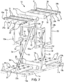
- FIGS. 6 and 7 Another embodiment of an adjustable frame assembly 10 is shown in FIGS. 6 and 7 .
- the adjustable frame assembly 10 includes a lower base arrangement, an upper base arrangement, and an adjustable frame structure connected between the lower and upper base arrangements.
- the adjustable frame structure is moveable between a first position in which the lower and upper base arrangements are spaced a smaller first distance apart and a second position in which the lower and upper base arrangements are spaced a second greater distance apart.
- the adjustable frame assembly 10 shown in FIGS. 6 and 7 may be fashioned from many of the same materials as the adjustable frame assembly 10 shown in FIGS. 1 and 2 .
- each base arrangement in FIGS. 6 and 7 may be similar to those of FIGS. 1 and 2 , except each base arrangement in FIGS. 6 and 7 includes first and second base sections 11a, 11b; 12a, 12b.
- the base sections may be similar to or different from one another.
- the lower base sections 11a, 11b may be similar to one another and generally coplanar.
- the upper base sections 12a, 12b may also be similar to one another and generally coplanar.
- Each lower base section 11a, 11b may include a lower frame 15a, 15b fashioned from lower frame elements 17 and a plurality of lower mounts 16 attached to the lower frame 15a, 15b, as previously described.
- Each upper base section 12a, 12b may include an upper frame 20a, 20b fashioned from upper frame elements 21 and a plurality of upper mounts 22 attached to the upper frame 20a, 20b, as previously described.
- each base section 11a, 11b; 12a, 12b may include a piping system 23a, 23b; 24a, 24b and all of the piping systems 23a, 23b; 24a, 24b may be similar to one another.
- each lower piping system 23a, 23b may be attached to the lower frame 15a, 15b and may include a distribution pipe 30 fluidly coupled to feed manifolds 25, as previously described.
- Each upper piping system 24a, 24b may be connected to an upper frame 20a, 20b and may include a collection pipe 31 fluidly coupled to filtrate manifolds 26, as previously described.
- the mounts and the piping system may be separate and distinct from one another, in the illustrated embodiment the lower mounts 16 may be integrated with the lower piping system 23a, 23b and the upper mounts 22 may be integrated with the upper piping system 24a, 24b, as previously described.
- the adjustable frame structure 13 of FIGS. 6 and 7 may be similar to the adjustable frame structure 13 of FIGS. 1-3 .
- the adjustable frame structure 13 of FIGS. 6 and 7 may include lower and upper frame assemblages 32, 33 moveably connected, e.g., slidingly mounted, to one another to move between the first position and the second position.
- the lower frame assemblage 32 may be connected between the first and second lower base sections 11a, 11b and may comprise opposed elongate beams 34, 35 attached to opposite edges of the lower base arrangement 11 and extending generally perpendicularly upwardly from the plane of the lower base sections 11a, 11b, as previously described.
- a cross brace 36 may be attached at the top of the beams 34, 35 and may extend between the beams 34, 35.
- the cross brace 36 may have a generally rounded cross section, e.g., may be a cylindrical pipe.
- the upper frame assemblage 33 of FIGS. 6 and 7 may be different from the upper frame assemblage 33 of FIGS. 1-3 .
- the upper frame assemblage 33 may be connected between the first and second upper base sections 12a, 12b and may comprise opposed short brackets 52 moveably mounted around the beams 34, 35 of the lower frame assemblage 32.
- the brackets 52 may be mounted to slide along the exterior of the beams 34, 35 of the lower frame assemblage 32.
- Struts for example, generally L-shaped struts 53a, 53b, may extend generally upwardly in opposite directions from each bracket 52 and may be attached, e.g., welded or bolted, to the bracket 52 on one end and an upper base section 12a, 12b, e.g., an upper frame 20a, 20b, on the other end.
- the struts 53a, 53b and the beam 34, 35 on each side of the adjustable frame structure 13 may be generally coplanar.
- a cross brace 42 may be attached to, and extend between, the brackets 52.
- the adjustable frame structure 10 of FIGS. 6 and 7 may be moved from a first position, in which the lower and upper base arrangements, e.g., the lower and upper base sections 11a, 11b; 12a, 12b, are spaced a smaller first distance apart, as shown in FIG. 6 , to a second position, in which the lower and upper base arrangements, e.g., the lower and upper base sections 11a, 11b; 12a, 12b, are spaced a larger second distance from one another.
- the adjustable frame assembly 10 In the first position, the adjustable frame assembly 10 is compact and easily shippable.
- the distance between the lower and upper base sections 11a, 11b; 12a, 12b may correspond to the height of the filter modules (not shown).
- the filter modules may be mounted to the adjustable frame assembly 10 to form a filter apparatus (not shown) with the ends of the filter modules positioned in and supported by the mounts 16, 22 and the piping system, e.g., the lower and upper piping systems 23a, 23b; 24a, 24b of the lower and upper base sections 11a, 11b; 12a, 12b, fluidly coupled between the filter modules and a fluid system (not shown).
- all of the filter modules may be connected in parallel to the filter system.
- filter apparatus may be arranged such that the filter modules positioned between the one set of corresponding lower and upper base sections may be fluidly coupled in series with the filter modules positioned between the other set of corresponding lower and upper base sections.
- the adjustable frame assembly 10 of FIGS. 6 and 7 may be larger than the adjustable frame assembly 10 of FIGS. 1-3 and a mechanical mechanism for moving, e.g., sliding, the adjustable frame structure 13 from the first position to the second position may be helpful.
- the cross brace 36 on the upper frame assemblage 33 may include two laterally spaced oblong openings 54, allowing a fork lift to engage and lift the upper frame assemblage 33 to the second position, sliding the brackets 52 upwardly along the beams 34, 35.
- a strap mechanism including a strap 55 and a strap ratchet 56 coupled to the strap 55 may be used to lift the upper frame assemblage 33 from the first position to the second position.
- the strap mechanism may be connected to one or more of the adjustable frame structure, the lower base arrangement, and the upper base arrangement to move the second frame assemblage along the first frame assemblage to the second position.
- the strap 55 may be connected at one end to a lower base section 11a, extended over the rounded cross brace 36 of the lower frame assemblage 32, and connected to the cross brace 42 of the upper frame assemblage 33.
- Operating the strap ratchet 56 shortens the strap 55 and slides the brackets 52 upwardly along the beams 34, 35, thereby pulling the upper frame assemblage 33 up to a second position.
- the upper frame assemblage 33 may be locked to the lower frame assemblage 32, for example, by bolting the brackets 52 to the beams 34, 35.
- the strap mechanism may also be connected to one or more of the adjustable frame structure, the lower base arrangement, and the upper base arrangement to lock the adjustable frame assembly in the first position.
- the strap 55 may be connected at one end to one edge of the lower base arrangement 11a, extended over the top of the upper base arrangement 12a, 12b and the adjustable frame structure 13, and connected at the other end to an opposite edge of the lower base arrangement 11b.
- the strap ratchet 56 may then be tightened to lock the adjustable frame assembly 10 in the first position.
- a similar strap mechanism may be arranged with the adjustable frame assembly of FIGS. 1-5 and used to lock the frame assembly in the first position and/or lift the upper frame assemblage along the lower frame assemblage from the first position to the second position.
Landscapes
- Chemical & Material Sciences (AREA)
- Chemical Kinetics & Catalysis (AREA)
- Engineering & Computer Science (AREA)
- General Engineering & Computer Science (AREA)
- Mechanical Engineering (AREA)
- Water Supply & Treatment (AREA)
- Filtering Of Dispersed Particles In Gases (AREA)
- Filtration Of Liquid (AREA)
Claims (15)
- Einstellbare Rahmeneinheit (10) für eine Mehrzahl von Filtermodulen (14), wobei die einstellbare Rahmeneinheit (10) umfasst:eine untere Basisanordnung (11) und eine obere Basisanordnung (12), wobei jede der Basisanordnungen (11, 12) eine Mehrzahl von Halterungen umfasst, welche angeordnet sind, um ein Ende einer Mehrzahl von Filtermodulen (14) aufzunehmen, und wobei mindestens eine der Basisanordnungen (11, 12) ein Rohrleitungssystem (23; 24) umfasst, welches angeordnet ist, um Fluid zu einem Ende der Mehrzahl von Filtermodulen (14) hin oder von diesem weg zu leiten, undeine einstellbare Rahmenstruktur (13), welche zwischen der unteren Basisanordnung (11) und der oberen Basisanordnung (12) verbunden ist, wobei die einstellbare Rahmenstruktur (13) zwischen einer ersten Position, in welcher die untere und die obere Basisanordnung (11, 12) um einen ersten Abstand voneinander beabstandet sind, und einer zweiten Position, in welcher die untere und die obere Basisanordnung (11, 12) um einen zweiten Abstand voneinander beabstandet sind, welcher größer ist als der erste Abstand, wobei der zweite Abstand zu einer Höhe der Mehrzahl von Filtermodulen (14) korrespondiert und es erlaubt, die Mehrzahl von Filtermodulen (14) an den Halterungen der unteren und der oberen Basisanordnung (11, 12) zu positionieren und an das Rohrleitungssystem (23; 24) zu koppeln;dadurch gekennzeichnet, dass die einstellbare Rahmenstruktur (13) eine erste Rahmenanordnung (32), welche mit der unteren Basisanordnung (11) verbunden ist, und eine zweite Rahmenanordnung (33), welche mit der oberen Basisanordnung (12) verbunden ist, umfasst, wobei die zweite Rahmenanordnung (33) mit der ersten Rahmenanordnung (32) verbunden ist, wobei die zweite Rahmenanordnung (33) entlang der ersten Rahmenanordnung (32) zwischen der ersten und der zweiten Position der einstellbaren Rahmenstruktur (13) beweglich ist.
- Einstellbare Rahmeneinheit (10) nach Anspruch 1, wobei die zweite Rahmenanordnung (33) verschieblich an der ersten Rahmenanordnung (32) montiert ist, wobei vorzugsweise die zweite Rahmenanordnung (33) teleskopartig an der ersten Rahmenanordnung (32) montiert ist.
- Einstellbare Rahmeneinheit (10) nach Anspruch 1 oder 2, wobei das Rohrleitungssystem ein unteres Rohrleitungssystem (23), welches von der unteren Basisanordnung (11) gehaltert ist, und ein oberes Rohrleitungssystem (24), welches von der oberen Basisanordnung (12) gehaltert ist, umfasst.
- Einstellbare Rahmeneinheit (10) nach Anspruch 1 oder 2, wobei das Rohrleitungssystem (23; 24) an der unteren Basisanordnung (11) gehaltert ist, wobei die untere Basisanordnung (11) einen ersten und einen zweiten Basisabschnitt aufweist, welche seitlich voneinander beabstandet sind, wobei die Mehrzahl von Halterungen eine erste Gruppe von Halterungen an dem ersten Basisabschnitt und eine zweite Gruppe von Halterungen an dem zweiten Basisabschnitt umfassen und das Rohrleitungssystem (23; 24) ein erstes Rohrleitungssystem umfasst, welches von dem ersten Basisabschnitt gehaltert ist, und ein zweites Rohrleitungssystem, welches von dem zweiten Basisabschnitt gehaltert ist, und wobei die einstellbare Rahmenstruktur mit der unteren Basisanordnung (11) zwischen dem ersten Basisabschnitt und dem zweiten Basisabschnitt verbunden ist.
- Einstellbare Rahmeneinheit (10) nach Anspruch 1, 2 oder 4, wobei das Rohrleitungssystem (23; 24) an der oberen Basisanordnung (12) gehaltert ist, wobei die obere Basisanordnung (12) einen ersten und einen zweiten Basisabschnitt aufweist, welche seitlich voneinander beabstandet sind, wobei die Mehrzahl von Halterungen eine erste Gruppe von Halterungen an dem ersten Basisabschnitt und eine zweite Gruppe von Halterungen an dem zweiten Basisabschnitt umfassen und das Rohrleitungssystem ein erstes Rohrleitungssystem umfasst, welches von dem ersten Basisabschnitt gehaltert ist, und ein zweites Rohrleitungssystem, welches von dem zweiten Basisabschnitt gehaltert ist, und wobei die einstellbare Rahmenstruktur mit der oberen Basisanordnung zwischen dem ersten Basisabschnitt und dem zweiten Basisabschnitt verbunden ist.
- Einstellbare Rahmeneinheit (10) nach einem der voranstehenden Ansprüche, wobei das Rohrleitungssystem (23; 24) umfasst: eine erste Vorrichtung, welche mit zwei oder mehr der Filtermodule (14) koppelbar ist, um Fluid auf die Filtermodule (14) zu verteilen, und eine zweite Vorrichtung, welche mit zwei oder mehr der Filtermodule (14) koppelbar ist, um Fluid aus der Mehrzahl von Filtermodulen zu sammeln, wobei optional eine der Vorrichtungen erste Vorrichtung und zweite Vorrichtung von der unteren Basisanordnung (11) gehaltert ist und die jeweils andere der Vorrichtungen erste Vorrichtung und zweite Vorrichtung von der oberen Basisanordnung (12) gehaltert ist.
- Einstellbare Rahmeneinheit (10) nach einem der voranstehenden Ansprüche, wobei die Halterungen in dem Rohrleitungssystem (23; 24) integriert sind und das Rohrleitungssystem (23; 24) über die Halterungen mit den Enden der Filtermodule koppelbar ist.
- Einstellbare Rahmeneinheit (10) nach einem der voranstehenden Ansprüche, ferner umfassend einen Gurtmechanismus mit einem Gurt (55) und einer mit dem Gurt (55) gekoppelten Gurtratsche (56), wobei der Gurtmechanismus mit einem oder mehreren von der einstellbaren Rahmenstruktur (13), der unteren Basisanordnung (11) und der oberen Basisanordnung (12) verbunden ist und dazu angeordnet ist, die zweite Rahmenanordnung (33) entlang der ersten Rahmenanordnung (32) zwischen der ersten und der zweiten Position der einstellbaren Rahmenstruktur (13) zu bewegen.
- Einstellbare Rahmeneinheit (10) nach einem der voranstehenden Ansprüche, ferner umfassend einen Gurtmechanismus mit einem Gurt (55), welcher mit einem oder mehreren von der einstellbaren Rahmenstruktur (13), der unteren Basisanordnung (11) und der oberen Basisanordnung (12) verbunden ist und dazu angeordnet ist, die zweite Rahmenanordnung (33) in der ersten Position der einstellbaren Rahmenstruktur (13) mit der ersten Rahmenanordnung (32) zu verriegeln.
- Verfahren zum Zusammenbauen einer Filtervorrichtung, welche die einstellbare Rahmeneinheit (10) nach einem der voranstehenden Ansprüche und eine Mehrzahl von Filtermodulen (14) umfasst, wobei das Verfahren umfasst:Bewegen einer einstellbaren Rahmenstruktur (13), welche zwischen einer unteren Basisanordnung (11) und einer oberen Basisanordnung (12) verbunden ist, von einer ersten Position, in welcher die untere Basisanordnung (11) um einen ersten Abstand von der oberen Basisanordnung (12) beabstandet ist, zu einer zweiten Position, in welcher die untere Basisanordnung (11) um einen zweiten, größeren Abstand von der oberen Basisanordnung (12) beabstandet ist, Verschieben einer zweiten Rahmenanordnung (33) der einstellbaren Rahmenstruktur (13) entlang einer ersten Rahmenanordnung (32) der einstellbaren Rahmenstruktur (13), Positionieren von einander gegenüberliegenden Enden einer Mehrzahl von Filtermodulen (14) in einer Mehrzahl von Halterungen an der unteren und oberen Basisanordnung (11, 12), wenn sich die einstellbare Rahmenstruktur (13) in der zweiten Position befindet; undVerbinden eines Rohrleitungssystems (23; 24) an mindestens einer von der unteren und der oberen Basisanordnung (11, 12) mit der Mehrzahl von Filtermodulen (14).
- Verfahren nach Anspruch 10, wobei das Bewegen der einstellbaren Rahmenstruktur (13) umfasst: Betätigen einer Gurtratsche (56), welche mit einem Gurt (55) gekoppelt ist, welcher mit einem oder mehreren von der einstellbaren Rahmenstruktur (13), der unteren Basisanordnung (11) und der oberen Basisanordnung (12) verbunden ist, wobei das Betätigen des Gurts ein Verschieben der zweiten Rahmenanordnung (33) der einstellbaren Rahmenstruktur (13) entlang der ersten Rahmenanordnung (32) der einstellbaren Rahmenstruktur (13) zwischen der ersten und der zweiten Position umfasst.
- Verfahren nach Anspruch 10 oder 11, wobei das Verbinden des Rohrleitungssystems (23; 24) umfasst: Verbinden eines unteren Rohrleitungssystems an der unteren Basisanordnung (11) mit einem Ende der Mehrzahl von Filtermodulen (14) und Verbinden eines oberen Rohrleitungssystems an der oberen Basisanordnung (12) mit einem anderen Ende der Mehrzahl von Filtermodulen (14), und/oder
wobei das Verbinden des Rohrleitungssystems (23; 24) mit der Mehrzahl von Filtermodulen (14) ein Positionieren der Enden der Filtermodule (14) in der Mehrzahl von in das Rohrleitungssystem (23; 24) integrierten Halterungen umfasst. - Verfahren nach einem der Ansprüche 10 bis 12, ferner umfassend: Entriegeln der einstellbaren Rahmenstruktur (13) aus einer verriegelten ersten Position, bevor die einstellbare Rahmenstruktur (13) zwischen der ersten und der zweiten Position bewegt wird.
- Verfahren nach Anspruch 13, wobei das Entriegeln der einstellbaren Rahmenstruktur (13) umfasst: Lösen eines Gurts (55) von einem oder mehreren von der einstellbaren Rahmenstruktur (13), dem unteren Basiselement und dem oberen Basiselement.
- Filtervorrichtung (50), umfassend:eine Rahmeneinheit (10) nach Anspruch 1 undeine Mehrzahl von Filtermodulen (14), wobei jedes Filtermodul (14) einander gegenüberliegende Enden und eine zu dem zweiten Abstand korrespondierende Höhe aufweist, wobei ein Ende jedes Filtermoduls (14) in einer der Halterungen des unteren Basisabschnitts (11a, 11b) positioniert ist und das andere Ende des Filtermoduls (14) in einer der Halterungen des oberen Basisabschnitts (12a, 12b) positioniert ist und wobei das Rohrleitungssystems (23; 24) mit der Mehrzahl von Filtermodulen (14) gekoppelt ist, um Fluid zu der Mehrzahl von Filtermodulen (14) hin oder von diesen weg zu leiten.
Applications Claiming Priority (1)
| Application Number | Priority Date | Filing Date | Title |
|---|---|---|---|
| US14/201,212 US9447911B2 (en) | 2014-03-07 | 2014-03-07 | Adjustable frame assemblies, methods for assembling a filter apparatus, and filter apparatuses |
Publications (2)
| Publication Number | Publication Date |
|---|---|
| EP2915571A1 EP2915571A1 (de) | 2015-09-09 |
| EP2915571B1 true EP2915571B1 (de) | 2019-11-06 |
Family
ID=52991443
Family Applications (1)
| Application Number | Title | Priority Date | Filing Date |
|---|---|---|---|
| EP15156705.4A Active EP2915571B1 (de) | 2014-03-07 | 2015-02-26 | Einstellbare rahmenbaugruppen, verfahren zur montage einer filtervorrichtung und filtervorrichtungen |
Country Status (5)
| Country | Link |
|---|---|
| US (1) | US9447911B2 (de) |
| EP (1) | EP2915571B1 (de) |
| CN (1) | CN104888517A (de) |
| AU (1) | AU2015200940B2 (de) |
| CA (1) | CA2883483C (de) |
Cited By (1)
| Publication number | Priority date | Publication date | Assignee | Title |
|---|---|---|---|---|
| DE102020103925A1 (de) | 2020-02-14 | 2021-08-19 | Sartorius Stedim Biotech Gmbh | Einweg-Vorrichtung zur Separation oder Aufreinigung eines großen Volumens eines Stoffgemischs |
Families Citing this family (13)
| Publication number | Priority date | Publication date | Assignee | Title |
|---|---|---|---|---|
| CN110430929B (zh) | 2016-11-08 | 2022-12-27 | 滨特尔过滤解决方案有限责任公司 | 颗粒分离系统和方法 |
| DE102017111133A1 (de) | 2017-05-22 | 2018-11-22 | Sartorius Stedim Biotech Gmbh | Vorkonfigurierte Einweg-Filtrationsvorrichtung |
| DE102017127933A1 (de) * | 2017-11-27 | 2019-05-29 | Sartorius Stedim Biotech Gmbh | Einweg-Vorrichtung zur Filtration eines großen Mediumvolumens |
| CN108404532B (zh) * | 2018-04-23 | 2020-07-10 | 界首市盈丰环保科技有限公司 | 一种除尘装置专用过滤系统 |
| CN109578692B (zh) * | 2018-12-25 | 2020-07-24 | 嵊州市越通非开挖建设有限公司 | 一种管道交叉铺设装置 |
| WO2021101614A1 (en) * | 2019-11-21 | 2021-05-27 | Hydranautics | Modular manifold for filtration modules |
| KR20210132921A (ko) * | 2020-04-28 | 2021-11-05 | 주식회사 아모그린텍 | 중력식 정수장치용 필터모듈 및 이를 포함하는 중력식 정수장치 |
| USD1025288S1 (en) | 2021-07-14 | 2024-04-30 | Emd Millipore Corporation | Filter assembly bracket |
| USD1024269S1 (en) | 2021-07-14 | 2024-04-23 | Emd Millipore Corporation | Filter assembly holder |
| USD1033591S1 (en) | 2021-07-14 | 2024-07-02 | Emd Millipore Corporation | Filter assembly stand |
| CN113522031A (zh) * | 2021-08-13 | 2021-10-22 | 厦门安力克膜科技有限公司 | 一种电渗析膜堆组器 |
| CN115650476B (zh) * | 2022-09-30 | 2025-07-29 | 广东邦普循环科技有限公司 | 一种膜法盐湖卤水提锂用便于自动更换滤膜的过滤装置 |
| CN118220436B (zh) * | 2024-04-08 | 2025-07-29 | 舟山中远海运重工有限公司 | 一种油轮油舱甲板疏水阀组组装单元及其使用方法 |
Family Cites Families (8)
| Publication number | Priority date | Publication date | Assignee | Title |
|---|---|---|---|---|
| US4479426A (en) * | 1982-11-01 | 1984-10-30 | Alfa-Laval Ab | Method of closing, compressing and opening of presses for membrane filters and apparatus for carrying out the method |
| US7037426B2 (en) * | 2000-05-04 | 2006-05-02 | Zenon Environmental Inc. | Immersed membrane apparatus |
| CA2348186A1 (en) | 2001-05-18 | 2002-11-18 | Zenon Environmental Inc. | Immersed membrane module |
| US6913690B2 (en) * | 2001-10-12 | 2005-07-05 | Enviro-Care Company, Inc. | Debris removal system |
| KR101331675B1 (ko) | 2007-10-12 | 2013-11-26 | 코오롱인더스트리 주식회사 | 중공사막 모듈의 장착 시스템 및 그 방법 |
| EP2331242B1 (de) | 2008-07-24 | 2018-09-05 | Evoqua Water Technologies LLC | Rahmensystem für membranfiltrationsmodule |
| EP2389238A4 (de) | 2009-01-14 | 2013-07-03 | Bl Technologies Inc | Eingetauchte membrankassette und bedienungsverfahren |
| US9446970B2 (en) | 2009-02-24 | 2016-09-20 | Mitsubishi Rayon Co., Ltd. | Membrane module unit and assembly method, disassembly method, and maintenance method for same, and water-treatment apparatus |
-
2014
- 2014-03-07 US US14/201,212 patent/US9447911B2/en not_active Expired - Fee Related
-
2015
- 2015-02-24 AU AU2015200940A patent/AU2015200940B2/en not_active Ceased
- 2015-02-26 EP EP15156705.4A patent/EP2915571B1/de active Active
- 2015-02-28 CN CN201510178424.1A patent/CN104888517A/zh active Pending
- 2015-03-02 CA CA2883483A patent/CA2883483C/en not_active Expired - Fee Related
Non-Patent Citations (1)
| Title |
|---|
| None * |
Cited By (2)
| Publication number | Priority date | Publication date | Assignee | Title |
|---|---|---|---|---|
| DE102020103925A1 (de) | 2020-02-14 | 2021-08-19 | Sartorius Stedim Biotech Gmbh | Einweg-Vorrichtung zur Separation oder Aufreinigung eines großen Volumens eines Stoffgemischs |
| US12616920B2 (en) | 2020-02-14 | 2026-05-05 | Sartorius Stedim Biotech Gmbh | Single-use device for the separation or filtering of a large volume of a mixture of substances |
Also Published As
| Publication number | Publication date |
|---|---|
| CA2883483A1 (en) | 2015-09-07 |
| US20150252934A1 (en) | 2015-09-10 |
| EP2915571A1 (de) | 2015-09-09 |
| US9447911B2 (en) | 2016-09-20 |
| CA2883483C (en) | 2017-01-17 |
| AU2015200940A1 (en) | 2015-09-24 |
| CN104888517A (zh) | 2015-09-09 |
| AU2015200940B2 (en) | 2016-04-07 |
Similar Documents
| Publication | Publication Date | Title |
|---|---|---|
| CA2883483C (en) | Adjustable frame assemblies, methods for assembling a filter apparatus, and filter apparatuses | |
| CN101820981B (zh) | 用于将过滤膜组件安装到框架结构中的系统和方法 | |
| US4461707A (en) | Ultrafiltration and reverse osmosis tubular membrane module | |
| EP2111289B1 (de) | Tauchmodul aus hohlfasermembranen | |
| US20200238216A1 (en) | Integrated membrane module rack | |
| CN103492053B (zh) | 交叉流过滤盒支架 | |
| AU2019386558B2 (en) | A filter device, and method of assembly | |
| EP3049177B1 (de) | Selbsttragende monoblockstruktur für membranfiltrationskartuschen | |
| EP2794077B1 (de) | Verteilerplatte für querstrom-filtrationskassetten | |
| EP2736619B1 (de) | Vorrichtung zur abtrennung von feststoffpartikeln aus flüssigkeiten und deren anwendung | |
| NL2003669C2 (en) | Apparatus and process for the separation of particulate matter from a fluid. | |
| WO2024145515A1 (en) | Integrated pre-filter for uf/mf membrane system | |
| US20240116000A1 (en) | Hollow fiber immersed membrane module and cassette with high packing density and vertical permeate port connections | |
| PL184643B1 (pl) | Układ filtracji membranowej w przepływie poprzecznym | |
| EP1946824B1 (de) | Filteranordnungen mit gemeinsamer Anschlussplatte und deren Verwendung | |
| CN113149252A (zh) | 一种反渗透浓缩液减量化设备 | |
| JP2013180223A (ja) | フィルタ装置 |
Legal Events
| Date | Code | Title | Description |
|---|---|---|---|
| PUAI | Public reference made under article 153(3) epc to a published international application that has entered the european phase |
Free format text: ORIGINAL CODE: 0009012 |
|
| AK | Designated contracting states |
Kind code of ref document: A1 Designated state(s): AL AT BE BG CH CY CZ DE DK EE ES FI FR GB GR HR HU IE IS IT LI LT LU LV MC MK MT NL NO PL PT RO RS SE SI SK SM TR |
|
| AX | Request for extension of the european patent |
Extension state: BA ME |
|
| 17P | Request for examination filed |
Effective date: 20160304 |
|
| RBV | Designated contracting states (corrected) |
Designated state(s): AL AT BE BG CH CY CZ DE DK EE ES FI FR GB GR HR HU IE IS IT LI LT LU LV MC MK MT NL NO PL PT RO RS SE SI SK SM TR |
|
| STAA | Information on the status of an ep patent application or granted ep patent |
Free format text: STATUS: EXAMINATION IS IN PROGRESS |
|
| 17Q | First examination report despatched |
Effective date: 20181008 |
|
| GRAP | Despatch of communication of intention to grant a patent |
Free format text: ORIGINAL CODE: EPIDOSNIGR1 |
|
| STAA | Information on the status of an ep patent application or granted ep patent |
Free format text: STATUS: GRANT OF PATENT IS INTENDED |
|
| INTG | Intention to grant announced |
Effective date: 20190517 |
|
| GRAS | Grant fee paid |
Free format text: ORIGINAL CODE: EPIDOSNIGR3 |
|
| GRAA | (expected) grant |
Free format text: ORIGINAL CODE: 0009210 |
|
| STAA | Information on the status of an ep patent application or granted ep patent |
Free format text: STATUS: THE PATENT HAS BEEN GRANTED |
|
| AK | Designated contracting states |
Kind code of ref document: B1 Designated state(s): AL AT BE BG CH CY CZ DE DK EE ES FI FR GB GR HR HU IE IS IT LI LT LU LV MC MK MT NL NO PL PT RO RS SE SI SK SM TR |
|
| REG | Reference to a national code |
Ref country code: GB Ref legal event code: FG4D |
|
| REG | Reference to a national code |
Ref country code: CH Ref legal event code: EP Ref country code: AT Ref legal event code: REF Ref document number: 1197990 Country of ref document: AT Kind code of ref document: T Effective date: 20191115 |
|
| REG | Reference to a national code |
Ref country code: IE Ref legal event code: FG4D |
|
| REG | Reference to a national code |
Ref country code: DE Ref legal event code: R096 Ref document number: 602015040941 Country of ref document: DE |
|
| REG | Reference to a national code |
Ref country code: NL Ref legal event code: MP Effective date: 20191106 |
|
| REG | Reference to a national code |
Ref country code: LT Ref legal event code: MG4D |
|
| PG25 | Lapsed in a contracting state [announced via postgrant information from national office to epo] |
Ref country code: FI Free format text: LAPSE BECAUSE OF FAILURE TO SUBMIT A TRANSLATION OF THE DESCRIPTION OR TO PAY THE FEE WITHIN THE PRESCRIBED TIME-LIMIT Effective date: 20191106 Ref country code: LT Free format text: LAPSE BECAUSE OF FAILURE TO SUBMIT A TRANSLATION OF THE DESCRIPTION OR TO PAY THE FEE WITHIN THE PRESCRIBED TIME-LIMIT Effective date: 20191106 Ref country code: GR Free format text: LAPSE BECAUSE OF FAILURE TO SUBMIT A TRANSLATION OF THE DESCRIPTION OR TO PAY THE FEE WITHIN THE PRESCRIBED TIME-LIMIT Effective date: 20200207 Ref country code: PL Free format text: LAPSE BECAUSE OF FAILURE TO SUBMIT A TRANSLATION OF THE DESCRIPTION OR TO PAY THE FEE WITHIN THE PRESCRIBED TIME-LIMIT Effective date: 20191106 Ref country code: PT Free format text: LAPSE BECAUSE OF FAILURE TO SUBMIT A TRANSLATION OF THE DESCRIPTION OR TO PAY THE FEE WITHIN THE PRESCRIBED TIME-LIMIT Effective date: 20200306 Ref country code: NO Free format text: LAPSE BECAUSE OF FAILURE TO SUBMIT A TRANSLATION OF THE DESCRIPTION OR TO PAY THE FEE WITHIN THE PRESCRIBED TIME-LIMIT Effective date: 20200206 Ref country code: NL Free format text: LAPSE BECAUSE OF FAILURE TO SUBMIT A TRANSLATION OF THE DESCRIPTION OR TO PAY THE FEE WITHIN THE PRESCRIBED TIME-LIMIT Effective date: 20191106 Ref country code: SE Free format text: LAPSE BECAUSE OF FAILURE TO SUBMIT A TRANSLATION OF THE DESCRIPTION OR TO PAY THE FEE WITHIN THE PRESCRIBED TIME-LIMIT Effective date: 20191106 Ref country code: LV Free format text: LAPSE BECAUSE OF FAILURE TO SUBMIT A TRANSLATION OF THE DESCRIPTION OR TO PAY THE FEE WITHIN THE PRESCRIBED TIME-LIMIT Effective date: 20191106 Ref country code: BG Free format text: LAPSE BECAUSE OF FAILURE TO SUBMIT A TRANSLATION OF THE DESCRIPTION OR TO PAY THE FEE WITHIN THE PRESCRIBED TIME-LIMIT Effective date: 20200206 |
|
| PG25 | Lapsed in a contracting state [announced via postgrant information from national office to epo] |
Ref country code: RS Free format text: LAPSE BECAUSE OF FAILURE TO SUBMIT A TRANSLATION OF THE DESCRIPTION OR TO PAY THE FEE WITHIN THE PRESCRIBED TIME-LIMIT Effective date: 20191106 Ref country code: IS Free format text: LAPSE BECAUSE OF FAILURE TO SUBMIT A TRANSLATION OF THE DESCRIPTION OR TO PAY THE FEE WITHIN THE PRESCRIBED TIME-LIMIT Effective date: 20200306 Ref country code: HR Free format text: LAPSE BECAUSE OF FAILURE TO SUBMIT A TRANSLATION OF THE DESCRIPTION OR TO PAY THE FEE WITHIN THE PRESCRIBED TIME-LIMIT Effective date: 20191106 |
|
| PG25 | Lapsed in a contracting state [announced via postgrant information from national office to epo] |
Ref country code: AL Free format text: LAPSE BECAUSE OF FAILURE TO SUBMIT A TRANSLATION OF THE DESCRIPTION OR TO PAY THE FEE WITHIN THE PRESCRIBED TIME-LIMIT Effective date: 20191106 |
|
| PG25 | Lapsed in a contracting state [announced via postgrant information from national office to epo] |
Ref country code: DK Free format text: LAPSE BECAUSE OF FAILURE TO SUBMIT A TRANSLATION OF THE DESCRIPTION OR TO PAY THE FEE WITHIN THE PRESCRIBED TIME-LIMIT Effective date: 20191106 Ref country code: EE Free format text: LAPSE BECAUSE OF FAILURE TO SUBMIT A TRANSLATION OF THE DESCRIPTION OR TO PAY THE FEE WITHIN THE PRESCRIBED TIME-LIMIT Effective date: 20191106 Ref country code: RO Free format text: LAPSE BECAUSE OF FAILURE TO SUBMIT A TRANSLATION OF THE DESCRIPTION OR TO PAY THE FEE WITHIN THE PRESCRIBED TIME-LIMIT Effective date: 20191106 Ref country code: ES Free format text: LAPSE BECAUSE OF FAILURE TO SUBMIT A TRANSLATION OF THE DESCRIPTION OR TO PAY THE FEE WITHIN THE PRESCRIBED TIME-LIMIT Effective date: 20191106 Ref country code: CZ Free format text: LAPSE BECAUSE OF FAILURE TO SUBMIT A TRANSLATION OF THE DESCRIPTION OR TO PAY THE FEE WITHIN THE PRESCRIBED TIME-LIMIT Effective date: 20191106 |
|
| REG | Reference to a national code |
Ref country code: DE Ref legal event code: R097 Ref document number: 602015040941 Country of ref document: DE |
|
| REG | Reference to a national code |
Ref country code: AT Ref legal event code: MK05 Ref document number: 1197990 Country of ref document: AT Kind code of ref document: T Effective date: 20191106 |
|
| PG25 | Lapsed in a contracting state [announced via postgrant information from national office to epo] |
Ref country code: SK Free format text: LAPSE BECAUSE OF FAILURE TO SUBMIT A TRANSLATION OF THE DESCRIPTION OR TO PAY THE FEE WITHIN THE PRESCRIBED TIME-LIMIT Effective date: 20191106 Ref country code: SM Free format text: LAPSE BECAUSE OF FAILURE TO SUBMIT A TRANSLATION OF THE DESCRIPTION OR TO PAY THE FEE WITHIN THE PRESCRIBED TIME-LIMIT Effective date: 20191106 |
|
| PLBE | No opposition filed within time limit |
Free format text: ORIGINAL CODE: 0009261 |
|
| STAA | Information on the status of an ep patent application or granted ep patent |
Free format text: STATUS: NO OPPOSITION FILED WITHIN TIME LIMIT |
|
| REG | Reference to a national code |
Ref country code: CH Ref legal event code: PL |
|
| 26N | No opposition filed |
Effective date: 20200807 |
|
| REG | Reference to a national code |
Ref country code: BE Ref legal event code: MM Effective date: 20200229 |
|
| PG25 | Lapsed in a contracting state [announced via postgrant information from national office to epo] |
Ref country code: LU Free format text: LAPSE BECAUSE OF NON-PAYMENT OF DUE FEES Effective date: 20200226 Ref country code: MC Free format text: LAPSE BECAUSE OF FAILURE TO SUBMIT A TRANSLATION OF THE DESCRIPTION OR TO PAY THE FEE WITHIN THE PRESCRIBED TIME-LIMIT Effective date: 20191106 |
|
| PG25 | Lapsed in a contracting state [announced via postgrant information from national office to epo] |
Ref country code: SI Free format text: LAPSE BECAUSE OF FAILURE TO SUBMIT A TRANSLATION OF THE DESCRIPTION OR TO PAY THE FEE WITHIN THE PRESCRIBED TIME-LIMIT Effective date: 20191106 Ref country code: AT Free format text: LAPSE BECAUSE OF FAILURE TO SUBMIT A TRANSLATION OF THE DESCRIPTION OR TO PAY THE FEE WITHIN THE PRESCRIBED TIME-LIMIT Effective date: 20191106 Ref country code: LI Free format text: LAPSE BECAUSE OF NON-PAYMENT OF DUE FEES Effective date: 20200229 Ref country code: CH Free format text: LAPSE BECAUSE OF NON-PAYMENT OF DUE FEES Effective date: 20200229 |
|
| PG25 | Lapsed in a contracting state [announced via postgrant information from national office to epo] |
Ref country code: IE Free format text: LAPSE BECAUSE OF NON-PAYMENT OF DUE FEES Effective date: 20200226 |
|
| PG25 | Lapsed in a contracting state [announced via postgrant information from national office to epo] |
Ref country code: BE Free format text: LAPSE BECAUSE OF NON-PAYMENT OF DUE FEES Effective date: 20200229 |
|
| PGFP | Annual fee paid to national office [announced via postgrant information from national office to epo] |
Ref country code: FR Payment date: 20210113 Year of fee payment: 7 Ref country code: IT Payment date: 20210112 Year of fee payment: 7 |
|
| PGFP | Annual fee paid to national office [announced via postgrant information from national office to epo] |
Ref country code: DE Payment date: 20210216 Year of fee payment: 7 Ref country code: GB Payment date: 20210217 Year of fee payment: 7 |
|
| PG25 | Lapsed in a contracting state [announced via postgrant information from national office to epo] |
Ref country code: TR Free format text: LAPSE BECAUSE OF FAILURE TO SUBMIT A TRANSLATION OF THE DESCRIPTION OR TO PAY THE FEE WITHIN THE PRESCRIBED TIME-LIMIT Effective date: 20191106 Ref country code: MT Free format text: LAPSE BECAUSE OF FAILURE TO SUBMIT A TRANSLATION OF THE DESCRIPTION OR TO PAY THE FEE WITHIN THE PRESCRIBED TIME-LIMIT Effective date: 20191106 Ref country code: CY Free format text: LAPSE BECAUSE OF FAILURE TO SUBMIT A TRANSLATION OF THE DESCRIPTION OR TO PAY THE FEE WITHIN THE PRESCRIBED TIME-LIMIT Effective date: 20191106 |
|
| PG25 | Lapsed in a contracting state [announced via postgrant information from national office to epo] |
Ref country code: MK Free format text: LAPSE BECAUSE OF FAILURE TO SUBMIT A TRANSLATION OF THE DESCRIPTION OR TO PAY THE FEE WITHIN THE PRESCRIBED TIME-LIMIT Effective date: 20191106 |
|
| REG | Reference to a national code |
Ref country code: DE Ref legal event code: R119 Ref document number: 602015040941 Country of ref document: DE |
|
| GBPC | Gb: european patent ceased through non-payment of renewal fee |
Effective date: 20220226 |
|
| PG25 | Lapsed in a contracting state [announced via postgrant information from national office to epo] |
Ref country code: FR Free format text: LAPSE BECAUSE OF NON-PAYMENT OF DUE FEES Effective date: 20220228 |
|
| PG25 | Lapsed in a contracting state [announced via postgrant information from national office to epo] |
Ref country code: GB Free format text: LAPSE BECAUSE OF NON-PAYMENT OF DUE FEES Effective date: 20220226 Ref country code: DE Free format text: LAPSE BECAUSE OF NON-PAYMENT OF DUE FEES Effective date: 20220901 |
|
| PG25 | Lapsed in a contracting state [announced via postgrant information from national office to epo] |
Ref country code: IT Free format text: LAPSE BECAUSE OF NON-PAYMENT OF DUE FEES Effective date: 20220226 |