EP2916063A1 - Appareil d'éclairage à del - Google Patents
Appareil d'éclairage à del Download PDFInfo
- Publication number
- EP2916063A1 EP2916063A1 EP13850576.3A EP13850576A EP2916063A1 EP 2916063 A1 EP2916063 A1 EP 2916063A1 EP 13850576 A EP13850576 A EP 13850576A EP 2916063 A1 EP2916063 A1 EP 2916063A1
- Authority
- EP
- European Patent Office
- Prior art keywords
- case part
- lighting apparatus
- led lighting
- light
- reflective
- Prior art date
- Legal status (The legal status is an assumption and is not a legal conclusion. Google has not performed a legal analysis and makes no representation as to the accuracy of the status listed.)
- Granted
Links
Images


Classifications
-
- F—MECHANICAL ENGINEERING; LIGHTING; HEATING; WEAPONS; BLASTING
- F21—LIGHTING
- F21S—NON-PORTABLE LIGHTING DEVICES; SYSTEMS THEREOF; VEHICLE LIGHTING DEVICES SPECIALLY ADAPTED FOR VEHICLE EXTERIORS
- F21S8/00—Lighting devices intended for fixed installation
- F21S8/02—Lighting devices intended for fixed installation of recess-mounted type, e.g. downlighters
-
- F—MECHANICAL ENGINEERING; LIGHTING; HEATING; WEAPONS; BLASTING
- F21—LIGHTING
- F21V—FUNCTIONAL FEATURES OR DETAILS OF LIGHTING DEVICES OR SYSTEMS THEREOF; STRUCTURAL COMBINATIONS OF LIGHTING DEVICES WITH OTHER ARTICLES, NOT OTHERWISE PROVIDED FOR
- F21V7/00—Reflectors for light sources
- F21V7/04—Optical design
-
- F—MECHANICAL ENGINEERING; LIGHTING; HEATING; WEAPONS; BLASTING
- F21—LIGHTING
- F21S—NON-PORTABLE LIGHTING DEVICES; SYSTEMS THEREOF; VEHICLE LIGHTING DEVICES SPECIALLY ADAPTED FOR VEHICLE EXTERIORS
- F21S8/00—Lighting devices intended for fixed installation
- F21S8/03—Lighting devices intended for fixed installation of surface-mounted type
-
- F—MECHANICAL ENGINEERING; LIGHTING; HEATING; WEAPONS; BLASTING
- F21—LIGHTING
- F21S—NON-PORTABLE LIGHTING DEVICES; SYSTEMS THEREOF; VEHICLE LIGHTING DEVICES SPECIALLY ADAPTED FOR VEHICLE EXTERIORS
- F21S8/00—Lighting devices intended for fixed installation
- F21S8/04—Lighting devices intended for fixed installation intended only for mounting on a ceiling or the like overhead structures
- F21S8/06—Lighting devices intended for fixed installation intended only for mounting on a ceiling or the like overhead structures by suspension
-
- F—MECHANICAL ENGINEERING; LIGHTING; HEATING; WEAPONS; BLASTING
- F21—LIGHTING
- F21V—FUNCTIONAL FEATURES OR DETAILS OF LIGHTING DEVICES OR SYSTEMS THEREOF; STRUCTURAL COMBINATIONS OF LIGHTING DEVICES WITH OTHER ARTICLES, NOT OTHERWISE PROVIDED FOR
- F21V21/00—Supporting, suspending, or attaching arrangements for lighting devices; Hand grips
- F21V21/14—Adjustable mountings
- F21V21/30—Pivoted housings or frames
-
- F—MECHANICAL ENGINEERING; LIGHTING; HEATING; WEAPONS; BLASTING
- F21—LIGHTING
- F21V—FUNCTIONAL FEATURES OR DETAILS OF LIGHTING DEVICES OR SYSTEMS THEREOF; STRUCTURAL COMBINATIONS OF LIGHTING DEVICES WITH OTHER ARTICLES, NOT OTHERWISE PROVIDED FOR
- F21V23/00—Arrangement of electric circuit elements in or on lighting devices
- F21V23/02—Arrangement of electric circuit elements in or on lighting devices the elements being transformers, impedances or power supply units, e.g. a transformer with a rectifier
- F21V23/023—Power supplies in a casing
-
- F—MECHANICAL ENGINEERING; LIGHTING; HEATING; WEAPONS; BLASTING
- F21—LIGHTING
- F21V—FUNCTIONAL FEATURES OR DETAILS OF LIGHTING DEVICES OR SYSTEMS THEREOF; STRUCTURAL COMBINATIONS OF LIGHTING DEVICES WITH OTHER ARTICLES, NOT OTHERWISE PROVIDED FOR
- F21V7/00—Reflectors for light sources
- F21V7/0008—Reflectors for light sources providing for indirect lighting
-
- F—MECHANICAL ENGINEERING; LIGHTING; HEATING; WEAPONS; BLASTING
- F21—LIGHTING
- F21V—FUNCTIONAL FEATURES OR DETAILS OF LIGHTING DEVICES OR SYSTEMS THEREOF; STRUCTURAL COMBINATIONS OF LIGHTING DEVICES WITH OTHER ARTICLES, NOT OTHERWISE PROVIDED FOR
- F21V7/00—Reflectors for light sources
- F21V7/0025—Combination of two or more reflectors for a single light source
- F21V7/0033—Combination of two or more reflectors for a single light source with successive reflections from one reflector to the next or following
- F21V7/0041—Combination of two or more reflectors for a single light source with successive reflections from one reflector to the next or following for avoiding direct view of the light source or to prevent dazzling
-
- F—MECHANICAL ENGINEERING; LIGHTING; HEATING; WEAPONS; BLASTING
- F21—LIGHTING
- F21V—FUNCTIONAL FEATURES OR DETAILS OF LIGHTING DEVICES OR SYSTEMS THEREOF; STRUCTURAL COMBINATIONS OF LIGHTING DEVICES WITH OTHER ARTICLES, NOT OTHERWISE PROVIDED FOR
- F21V7/00—Reflectors for light sources
- F21V7/005—Reflectors for light sources with an elongated shape to cooperate with linear light sources
-
- F—MECHANICAL ENGINEERING; LIGHTING; HEATING; WEAPONS; BLASTING
- F21—LIGHTING
- F21Y—INDEXING SCHEME ASSOCIATED WITH SUBCLASSES F21K, F21L, F21S and F21V, RELATING TO THE FORM OR THE KIND OF THE LIGHT SOURCES OR OF THE COLOUR OF THE LIGHT EMITTED
- F21Y2103/00—Elongate light sources, e.g. fluorescent tubes
- F21Y2103/10—Elongate light sources, e.g. fluorescent tubes comprising a linear array of point-like light-generating elements
-
- F—MECHANICAL ENGINEERING; LIGHTING; HEATING; WEAPONS; BLASTING
- F21—LIGHTING
- F21Y—INDEXING SCHEME ASSOCIATED WITH SUBCLASSES F21K, F21L, F21S and F21V, RELATING TO THE FORM OR THE KIND OF THE LIGHT SOURCES OR OF THE COLOUR OF THE LIGHT EMITTED
- F21Y2115/00—Light-generating elements of semiconductor light sources
- F21Y2115/10—Light-emitting diodes [LED]
Definitions
- the present invention relates to an LED lighting apparatus, and more particularly, to an LED lighting apparatus that can provide a variety of purposes and an extended installation function thereof.
- indoor lighting apparatuses using LEDs may be divided into apparatuses of a bulb type that replace typical bulbs, and surface-lighting apparatuses that replace fluorescent lamps.
- the Patent discloses a configuration that includes a substrate having a plurality of LEDs for emitting light upwards mounted thereon, and at least one diffusion layer on the surface of the substrate, such that the light emitted from the plurality of LEDs is diffused to illuminate the entire surface of a specific area at a uniform intensity of illumination, as shown in the primary drawing, i.e., FIG. 4 .
- Such a configuration is usually adopted by the typical surface-lighting apparatuses, wherein the diffusion plate can prevent the light from emitting intensively from a specific portion to thereby eliminate the dazzle of a light, but the light-efficiency is lowered due to a significant light loss.
- the number of LEDs used in the lighting apparatus of 20 W is only half the number of LEDs used in the lighting apparatus of 40 W, so the gap between the LEDs become bigger due to the decrease in the number of LEDs. Accordingly, the diffusion plate just below the light-emitting surface of the LEDs shows bright portions and dark portions, which cause uneven illumination on the light-emitting surface.
- the distance between the LEDs and the diffusion plate should be adjusted to be longer through the change of the design.
- the size of the light-emitting unit is to be reduced by half, another half of the light-emitting unit should be replaced with a reflection plate.
- one aspect of the present invention provides an LED lighting apparatus that emits a uniform light with low electric power consumption without changing the size of the lighting fixture.
- another aspect of the present invention provides an LED lighting apparatus in which the number of LEDs is reduced to thereby minimize the problem caused by the heat emitted from the LEDs.
- Still another aspect of the present invention provides an LED lighting apparatus that can prevent the dazzle of a light without using the diffusion plate.
- Still yet another aspect of the present invention provides an LED lighting apparatus an LED lighting apparatus that can provide a variety of purposes by easily replacing existing indoor fluorescent lighting fixtures, and can provide an extended installation function to satisfy the intensity of illumination required in the installed location thereof.
- an LED lighting apparatus including: a case part which covers a residual part, excluding a light-emitting surface, to provide a reflective space and has a predetermined depth, in which an upper edge of the inside thereof has a slope; a receiving surface in which a lateral surface portion of the case part is bent toward the inside of the case; a substrate fixed on the receiving surface and in which a plurality of LEDs are provided; and a reflective part which is located in an upper center portion of the inside of the case part so as to reflect the light of the LEDs and enables reflection and diffusion of light within the reflective space provided from the case part.
- the LED lighting apparatus of the present invention includes a case that provides a reflective space to enable the surface-lighting by reflection, and LEDs that are positioned to be slanted at the side of a light-emitting surface of the case and of which a light-emitting surface faces the reflective space so that the light emitted from the LED is reflected by the case to thereby attain the surface-lighting. Therefore, the present invention can provide an LED lighting apparatus that emits a uniform light with low electric power consumption without changing the size of a lighting fixture.
- the lighting apparatus of volume-light-emitting can prevent the dazzle of a light without the diffusion plate by making the surface-lighting through the first reflection and the diffusion of a light of the LED by a reflection surface.
- the lighting apparatus of the present invention can improve the light-efficiency by removing the diffusion plate to thereby reduce the number of LEDs.
- the electric power consumption and the manufacturing cost can be reduced as well.
- the weight of the lighting apparatus can be reduced, and the structure thereof can be simplified.
- the present invention can provide a variety of purposes by easily replacing existing recessed fluorescent lighting fixtures, and can provide a lighting apparatus that satisfies an intensity of illumination required in the installed location thereof through the extension of the number of LEDs installed as needed.
- FIG. 1 is an exploded perspective view of an LED lighting apparatus according to a preferred embodiment of the present invention
- FIG. 2 is a sectional view of a coupled configuration, which is taken in the direction of A-A of FIG. 1 .
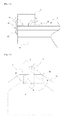
- an LED lighting apparatus includes: a case part 10 that has a shape of a box with a light-emitting surface 13 at the bottom thereof, a slope 11 formed to be slated on the upper portion inside the case part, and a receiving surface 12 formed to be slanted at the edges of both sides of the light-emitting surface 13; a reflective part 20 formed on the upper center portion inside the case part 10; and a substrate 30 that is installed on the receiving surface 12 and has a plurality of LEDs 31 mounted thereon.
- the case part 10 is shaped into a box with an opening at the bottom thereof. That is, the case part 10 is formed of the light-emitting surface 13 at the bottom, and the remaining space except for the light-emitting surface 13 is enclosed to thereby provide a space in which the light of the LED 31 can be effectively reflected inside the case part 10.
- the sides of the case part 10 are vertical with respect to the ground, and an end portion of the side is bent toward the inside of the case part 10 to thereby form the receiving surface 12.
- the receiving surface 12 is at an acute angle of less than 90° to the side of the case part 10.
- the receiving surface 12 may be formed at both facing sides with respect to the light-emitting surface 13, and if necessary, it may be formed at one side or four sides.
- the upper surface inside the case part 10 is flat on the center thereof, and the slope 11 is formed on the surface between the flat center portion and the sides of the case part.
- the slope 11 may be slanted more as it goes to the side of the case part 10.
- the reflective part 20 is positioned on the flat center portion of the upper surface inside the case part 10.
- the reflective part 20 is shaped into an inverted triangle in its section, and it extends to the boundary of the slope 11 of the case part 10.
- the highest portion of the space between the case part 10 and the reflective part 20 to the ceiling is position on the boundary between the slope 11 of the case part 10 and the reflective part 20.
- the substrate 30, on which a plurality of LEDs 31 is mounted, is fixed on the receiving surface 12. Accordingly, the light-emitting surface of the plurality of LEDs 31 is perpendicular to the receiving surface 12, and the light emitted from the LEDs 31 directly illuminates the inner surface of the side of the case part 10.
- FIG. 3 is a conceptual diagram in which the light is reflected in the LED lighting apparatus according to the present invention.
- the light of the LED 31 is reflected by the side of the case part 10 to then continue to be reflected by the slope 11 of the case part 10 and the reflective part 20.
- the light that has been captured emits downwards through the light-emitting surface 13 to illuminate.
- the present invention provides the surface-lighting by the light that has been captured in the space of the case part 10 rather than direct illumination of the LED light, so the dazzle of a light can be attenuated without using lenses or diffusion plates.
- the present invention can improve the light-efficiency by eliminating the diffusion plate. Accordingly, the number of LEDs 31 can be reduced with respect to the same intensity of illumination, so a lighting apparatus of low electric power consumption can be provided.
- the present invention can prevent the reduction of LED life-span due to the heat generation without adopting a separate heat-radiating structure.
- the present invention does not adopt the heat-radiating structure. Since the LEDs of typical LED lighting apparatuses are installed on the ceiling, the heat radiation by air convection is not easy. Therefore, the typical LED lighting apparatuses have been developed to adopt a separate heat-radiating structure. However, the present invention has a structure in which the LEDs 31 are installed to be spaced from the ceiling, which facilitates the heat radiation by air convection.
- FIGs. 4 and 5 are sectional views of an LED lighting apparatuses according to other embodiments of the present invention, respectively.
- the reflective part 20 may be shaped into a semi-circle ( FIG. 4 ), or may have a reflection surface of an inverted triangle, on which a plurality of stepped protrusions or embossments is formed, to have an uneven roughness.
- the reflection surface having an uneven roughness in FIG. 5 may be applied to the reflective part 20 of FIG. 4 .
- the reflective part 20 in the shape of a semi-circle in its section in FIG. 4 , and the inverted triangle structure having a plurality of stepped protrusions may diversify the reflection angle of light so that reflection and diffusion of light can be made diversely and irregularly within the space of the case part 10.
- Such diverse and irregular reflection and diffusion of light may cause the diffusion of light to be more uniform, so the light emitted through the light-emitting surface 13 may be more similar to that of the surface-lighting source.
- any structure by which the light emitted from the LED 31 can be diffused in the space in the case part 10 may be applied to the present invention regardless of its detailed configuration.
- FIG. 6 is a sectional view of a configuration that can attain a high intensity of illumination using the present invention.
- the present invention may be applied to the places that require a relatively high intensity of illumination by combining a plurality of LED lighting apparatuses shown in FIG. 2 .
- the place that requires a relatively high intensity of illumination may be a place where the lighting apparatus is installed at a high position, such as spotlights at the factory, or streetlights.
- FIG. 6 shows a configuration in which a plurality of LED lighting apparatuses are connected to satisfy a required intensity of illumination so that the outer surfaces of the sides of the case parts 10 contact with each other. This shows that the uniform design using a single LED lighting apparatus as a unit can be applied according to the required intensity of illumination without changing the design of the case part 10.
- FIG. 7 illustrates a sectional view of an LED lighting apparatus according to another embodiment of the present invention.
- the upper and center portion of the case part 10 is bent into the shape of the reflective part 20 rather than adopting the reflective part 20 of the embodiments above.
- the light of the LED 31 can be reflected and diffused as enough of the reflective part 20 of the embodiments above in the case part 10.
- the reflective part 20 may be a component separated from the case part 10, or the reflective part 20 may be integrally formed with the case part 10 as a single body by transforming the shape of the case part 10.
- FIG. 8 illustrates a sectional view of an LED lighting apparatus according to still another embodiment of the present invention.
- the upper and center portion inside the case part 10 is flat, different from the embodiment of FIG. 7 .
- the light of the LED 31 may be reflected and diffused in the case part 10, only depending on an angle between the receiving surface 12 and the inner surface of the side of the case part 10, and the degree of the slope 11 at the upper edge inside the case part 10 to thereby obtain the surface-light-emitting.
- FIG. 9 illustrates a sectional view of an LED lighting apparatus according to still yet another embodiment of the present invention.
- the slopes 11 meets each other at the upper and center portion of the case part 10 without adopting the reflective part 20 that is integrally formed with the case part 10.
- the light of the LEDs 31 may be reflected and diffused in the case part 10, depending on an angle between the receiving surface 12 and the inner surface of the side of the case part 10, and the degree of the slope 11 to thereby attain the surface-light-emitting at the light-emitting surface 13.
- FIG. 10 is a view illustrating an example of installation of an LED lighting apparatus according to the present invention
- FIG. 11 is a sectional view taken along the line A-A of FIG. 10
- FIG. 12 is a partial side view of FIG. 10 to describe the operation thereof.
- a plurality of LED lighting apparatuses may be installed and fixed at both ends on the lower surfaces of a pair of support frames 2 that have socket 3 on the lower surface.
- the support frame 2 includes a rotating latch 40 on the side surface thereof, which rotates about a rotating axis 41 to connect with a fixing protrusion 42 formed on both sides of the LED lighting apparatus 1 so that the LED lighting apparatus 1 is detachably installed.
- the rotating latch 40 has a planar shape, and may rotate with its position fixed by the rotating axis 41.
- the rotating latch 40 has a groove formed in the direction of rotation, and the fixing protrusion 42 fits into the groove to thereby fix the LED lighting apparatus 1 to the support frame 2.
- the LED lighting apparatus 1 includes a plug 5 protruding from the portion that makes contact with the support frame 2.
- the plug 5 is inserted into the socket 3 provided in the support frame 2 to be supplied with the electric power, and the plug 5 is connected with a cable to supply the electric power to the substrate 30 on the receiving surface 12.
- the socket 3 is configured to have an elastic force acting on the side surface of the plug 5 so that the plug 5 is prevented from easily popping out to be thereby in the stable supply of the electric power.
- the LED lighting apparatus 1 according to the present invention can be easily attached and detached by the rotating latch 40 as shown in FIG. 12 .
- a plurality of LED lighting apparatuses may be installed on the support frame 2 by the rotating latch 40 as needed to provide a lighting apparatus of the intensity of illumination that satisfies the purpose of use, and a spoiled LED lighting apparatus 1 can be easily replaced with a new one.
- Undescribed reference numeral 6 denotes a fixing frame that connects the pair of support frames 2 to fix the same.
- the fixing frame 6 is further provided with a wire for installing the same on the ceiling or other places.
- the fixing frame 2 may further include a power supply unit that converts an alternating current supplied from the outside into a direct current to be thereby supplied to the socket 3 through a substrate 4 provided on at least one of the pair of support frames 2.
- the present invention according to the configuration as described above can be easily attached and detached, and each of the LED lighting apparatus can be separately replaced as needed so that the cost of repair and maintenance can be reduced.
- the entire area of the inner surface of the case part 10 may be coated with a reflection surface, or a reflection sheet may be attached thereon.
- the present invention can provide a uniform intensity of illumination at low power consumption, and can considerably reduce the dazzle of a light compared to other LED lighting apparatuses.
- the present invention can easily replace typical fluorescent lighting fixtures, so it has industrial usability.
Landscapes
- Engineering & Computer Science (AREA)
- General Engineering & Computer Science (AREA)
- Power Engineering (AREA)
- Non-Portable Lighting Devices Or Systems Thereof (AREA)
- Arrangement Of Elements, Cooling, Sealing, Or The Like Of Lighting Devices (AREA)
- Fastening Of Light Sources Or Lamp Holders (AREA)
Applications Claiming Priority (3)
| Application Number | Priority Date | Filing Date | Title |
|---|---|---|---|
| KR20120121277 | 2012-10-30 | ||
| KR1020130073097A KR20140055943A (ko) | 2012-10-30 | 2013-06-25 | 엘이디 조명장치 |
| PCT/KR2013/009629 WO2014069857A1 (fr) | 2012-10-30 | 2013-10-28 | Appareil d'éclairage à del |
Publications (3)
| Publication Number | Publication Date |
|---|---|
| EP2916063A1 true EP2916063A1 (fr) | 2015-09-09 |
| EP2916063A4 EP2916063A4 (fr) | 2016-06-08 |
| EP2916063B1 EP2916063B1 (fr) | 2017-09-20 |
Family
ID=50887485
Family Applications (1)
| Application Number | Title | Priority Date | Filing Date |
|---|---|---|---|
| EP13850576.3A Not-in-force EP2916063B1 (fr) | 2012-10-30 | 2013-10-28 | Appareil d'éclairage à del |
Country Status (6)
| Country | Link |
|---|---|
| US (1) | US9810399B2 (fr) |
| EP (1) | EP2916063B1 (fr) |
| JP (2) | JP6379098B2 (fr) |
| KR (1) | KR20140055943A (fr) |
| AU (1) | AU2013338872B2 (fr) |
| WO (1) | WO2014069857A1 (fr) |
Families Citing this family (14)
| Publication number | Priority date | Publication date | Assignee | Title |
|---|---|---|---|---|
| KR20140055943A (ko) * | 2012-10-30 | 2014-05-09 | 주식회사 케이엠더블유 | 엘이디 조명장치 |
| JP6226183B2 (ja) * | 2013-11-05 | 2017-11-08 | レシップホールディングス株式会社 | 照明器具 |
| JP6067946B2 (ja) * | 2013-11-18 | 2017-01-25 | フィリップス ライティング ホールディング ビー ヴィ | 音響照明タイル |
| DE202014103605U1 (de) * | 2014-08-04 | 2014-08-21 | Brillant Ag | Elektrische Leuchte |
| CN104154446A (zh) * | 2014-08-07 | 2014-11-19 | 张勇 | 一种新式反射型led日光灯管 |
| KR101601531B1 (ko) * | 2014-11-07 | 2016-03-10 | 주식회사 지엘비젼 | 조명장치 |
| ITUA20161504A1 (it) * | 2016-03-09 | 2017-09-09 | Neri S P A | Ottica e corpo illuminante |
| WO2018215345A1 (fr) | 2017-05-25 | 2018-11-29 | Philips Lighting Holding B.V. | Luminaire |
| US10670205B2 (en) | 2018-03-09 | 2020-06-02 | Finelite Inc. | Open channel LED light fixture for indirect lighting |
| US10718476B2 (en) * | 2018-03-09 | 2020-07-21 | Finelite Inc. | LED light fixture for indirect lighting with adaptable baffle structure |
| NL2022161B1 (nl) * | 2018-12-10 | 2020-07-02 | Veko Lightsystems Int B V | Van leds voorzien lichtarmatuur voor grote lichtopbrengst |
| US11781735B2 (en) * | 2019-06-03 | 2023-10-10 | Modulex Inc. | Lighting unit body |
| US10928020B1 (en) * | 2019-08-22 | 2021-02-23 | Usg Interiors, Llc | Light bar for suspended ceiling |
| JP7399678B2 (ja) * | 2019-10-28 | 2023-12-18 | 株式会社ダイセル | 光半導体装置用樹脂成形体及び光半導体装置 |
Family Cites Families (25)
| Publication number | Priority date | Publication date | Assignee | Title |
|---|---|---|---|---|
| US2721635A (en) * | 1953-02-16 | 1955-10-25 | Fullerton Mfg Corp | Door assembly |
| JPH06131905A (ja) * | 1992-10-14 | 1994-05-13 | Tokyo Electric Co Ltd | 照明器具 |
| JPH11134913A (ja) * | 1997-10-31 | 1999-05-21 | Toshiba Lighting & Technology Corp | 照明器具 |
| US6149283A (en) * | 1998-12-09 | 2000-11-21 | Rensselaer Polytechnic Institute (Rpi) | LED lamp with reflector and multicolor adjuster |
| JP4527230B2 (ja) * | 2000-02-28 | 2010-08-18 | 三菱電機照明株式会社 | 面発光led光源 |
| JP2003036722A (ja) * | 2001-07-25 | 2003-02-07 | Toshiba Lighting & Technology Corp | 照明器具 |
| US7635198B2 (en) * | 2004-06-18 | 2009-12-22 | Acuity Brands, Inc. | Replacement light fixture and lens assembly for same |
| US7255459B2 (en) * | 2005-12-16 | 2007-08-14 | United Microdisplay Optronics Corp. | Light emitting diode light source |
| US7658506B2 (en) * | 2006-05-12 | 2010-02-09 | Philips Solid-State Lighting Solutions, Inc. | Recessed cove lighting apparatus for architectural surfaces |
| US20080030982A1 (en) * | 2006-08-04 | 2008-02-07 | Vode Llc | Modular lighting system |
| US8374498B2 (en) * | 2006-09-29 | 2013-02-12 | Microscan Systems, Inc. | Systems and/or devices for camera-based inspections |
| JP5030661B2 (ja) * | 2007-05-16 | 2012-09-19 | シャープ株式会社 | 照明装置 |
| EP2843464A1 (fr) * | 2007-05-29 | 2015-03-04 | Koninklijke Philips N.V. | Dispositif d'éclairage ayant une fenêtre de sortie de lumière |
| JP5475684B2 (ja) * | 2007-12-18 | 2014-04-16 | コーニンクレッカ フィリップス エヌ ヴェ | 照明システム、照明器具及びバックライトユニット |
| JP2010033893A (ja) * | 2008-07-29 | 2010-02-12 | Nec Lighting Ltd | 発光デバイスおよび光の放射方法 |
| EP2326869B1 (fr) * | 2008-09-12 | 2016-06-29 | Koninklijke Philips N.V. | Luminaire et system d'eclairage |
| KR100998980B1 (ko) | 2008-09-12 | 2010-12-09 | 자화전자(주) | 무경계면을 가진 직하 배치 방식의 엘이디 조명 장치 |
| KR20100103327A (ko) * | 2009-03-13 | 2010-09-27 | 이엔지테크놀러지 주식회사 | 형광등기구 |
| US8000594B2 (en) * | 2009-07-02 | 2011-08-16 | Microscan Systems, Inc. | Diffuse reflective illuminator |
| KR101114159B1 (ko) * | 2009-07-23 | 2012-03-09 | 엘지이노텍 주식회사 | 발광 장치 |
| US8197105B2 (en) * | 2009-08-13 | 2012-06-12 | Intematix Corporation | LED-based lamps |
| JP5421711B2 (ja) * | 2009-09-30 | 2014-02-19 | イーデーエム株式会社 | 照明装置 |
| KR101652816B1 (ko) * | 2010-04-10 | 2016-09-01 | 엘지이노텍 주식회사 | 조명 장치 |
| JP2012204146A (ja) * | 2011-03-25 | 2012-10-22 | Toshiba Lighting & Technology Corp | Led照明器具 |
| KR20140055943A (ko) * | 2012-10-30 | 2014-05-09 | 주식회사 케이엠더블유 | 엘이디 조명장치 |
-
2013
- 2013-06-25 KR KR1020130073097A patent/KR20140055943A/ko not_active Ceased
- 2013-10-28 EP EP13850576.3A patent/EP2916063B1/fr not_active Not-in-force
- 2013-10-28 AU AU2013338872A patent/AU2013338872B2/en not_active Ceased
- 2013-10-28 JP JP2015540597A patent/JP6379098B2/ja not_active Expired - Fee Related
- 2013-10-28 WO PCT/KR2013/009629 patent/WO2014069857A1/fr not_active Ceased
-
2015
- 2015-04-29 US US14/699,317 patent/US9810399B2/en active Active
-
2017
- 2017-03-14 JP JP2017048444A patent/JP2017103259A/ja active Pending
Also Published As
| Publication number | Publication date |
|---|---|
| AU2013338872A1 (en) | 2015-06-11 |
| EP2916063B1 (fr) | 2017-09-20 |
| JP2017103259A (ja) | 2017-06-08 |
| JP6379098B2 (ja) | 2018-08-22 |
| WO2014069857A1 (fr) | 2014-05-08 |
| US20150241023A1 (en) | 2015-08-27 |
| AU2013338872B2 (en) | 2016-12-22 |
| EP2916063A4 (fr) | 2016-06-08 |
| JP2015537348A (ja) | 2015-12-24 |
| US9810399B2 (en) | 2017-11-07 |
| KR20140055943A (ko) | 2014-05-09 |
Similar Documents
| Publication | Publication Date | Title |
|---|---|---|
| US9810399B2 (en) | LED lighting apparatus | |
| EP2752617B1 (fr) | Lampe sphérique avec dissipation de chaleur facile | |
| US20110002124A1 (en) | Wide angle led lamp structure | |
| CA2898902A1 (fr) | Module d'eclairage del et methode d'installation associee | |
| US10066790B2 (en) | Fluorescent lamp-type LED lighting device | |
| TW201632780A (zh) | 嵌入式燈具的改裝套件和改裝方法 | |
| KR20100084768A (ko) | 눈부심 방지 기능을 갖는 엘이디 조명등 | |
| KR101023826B1 (ko) | 전구형 엘이디 램프 | |
| KR200479710Y1 (ko) | 엘이디를 이용한 다색 실내등 | |
| JP5322292B2 (ja) | Ledユニットおよび照明器具 | |
| CN104566031A (zh) | 一种照明灯及其安装方法 | |
| JP2021157901A (ja) | 筒型照明ランプ | |
| KR20160126385A (ko) | 눈부심 방지용 엘이디 조명장치 | |
| CN216643877U (zh) | 防眩光灯具 | |
| KR101652816B1 (ko) | 조명 장치 | |
| KR101652775B1 (ko) | 조명 장치 | |
| KR101092593B1 (ko) | 엘이디 형광등 | |
| KR101278039B1 (ko) | 자연친화적 방열구조를 포함하는 눈부심 방지형 매입 등기구 | |
| CN102781807A (zh) | 电梯的轿厢内照明装置 | |
| KR200373584Y1 (ko) | 매입형 조명기구 | |
| KR200430730Y1 (ko) | 휘도증진수단이 구비된 비상조명등 | |
| JP2013222509A (ja) | 照明装置 | |
| TWM485358U (zh) | Led燈組結構 | |
| KR20150001097U (ko) | 개선된 구조를 갖는 소켓결합식 엘이디램프를 구비한 슬림형 조명등 |
Legal Events
| Date | Code | Title | Description |
|---|---|---|---|
| PUAI | Public reference made under article 153(3) epc to a published international application that has entered the european phase |
Free format text: ORIGINAL CODE: 0009012 |
|
| 17P | Request for examination filed |
Effective date: 20150519 |
|
| AK | Designated contracting states |
Kind code of ref document: A1 Designated state(s): AL AT BE BG CH CY CZ DE DK EE ES FI FR GB GR HR HU IE IS IT LI LT LU LV MC MK MT NL NO PL PT RO RS SE SI SK SM TR |
|
| AX | Request for extension of the european patent |
Extension state: BA ME |
|
| DAX | Request for extension of the european patent (deleted) | ||
| RA4 | Supplementary search report drawn up and despatched (corrected) |
Effective date: 20160506 |
|
| RIC1 | Information provided on ipc code assigned before grant |
Ipc: F21V 7/04 20060101AFI20160429BHEP Ipc: F21S 8/06 20060101ALI20160429BHEP Ipc: F21Y 115/10 20160101ALI20160429BHEP Ipc: F21V 17/00 20060101ALI20160429BHEP |
|
| RIC1 | Information provided on ipc code assigned before grant |
Ipc: F21Y 115/10 20160101ALI20170201BHEP Ipc: F21V 7/04 20060101AFI20170201BHEP Ipc: F21V 17/00 20060101ALI20170201BHEP Ipc: F21S 8/06 20060101ALI20170201BHEP |
|
| GRAP | Despatch of communication of intention to grant a patent |
Free format text: ORIGINAL CODE: EPIDOSNIGR1 |
|
| STAA | Information on the status of an ep patent application or granted ep patent |
Free format text: STATUS: GRANT OF PATENT IS INTENDED |
|
| INTG | Intention to grant announced |
Effective date: 20170403 |
|
| GRAS | Grant fee paid |
Free format text: ORIGINAL CODE: EPIDOSNIGR3 |
|
| GRAA | (expected) grant |
Free format text: ORIGINAL CODE: 0009210 |
|
| STAA | Information on the status of an ep patent application or granted ep patent |
Free format text: STATUS: THE PATENT HAS BEEN GRANTED |
|
| AK | Designated contracting states |
Kind code of ref document: B1 Designated state(s): AL AT BE BG CH CY CZ DE DK EE ES FI FR GB GR HR HU IE IS IT LI LT LU LV MC MK MT NL NO PL PT RO RS SE SI SK SM TR |
|
| REG | Reference to a national code |
Ref country code: GB Ref legal event code: FG4D |
|
| REG | Reference to a national code |
Ref country code: CH Ref legal event code: EP |
|
| REG | Reference to a national code |
Ref country code: AT Ref legal event code: REF Ref document number: 930444 Country of ref document: AT Kind code of ref document: T Effective date: 20171015 |
|
| REG | Reference to a national code |
Ref country code: IE Ref legal event code: FG4D |
|
| REG | Reference to a national code |
Ref country code: DE Ref legal event code: R096 Ref document number: 602013026978 Country of ref document: DE |
|
| REG | Reference to a national code |
Ref country code: NL Ref legal event code: MP Effective date: 20170920 |
|
| PG25 | Lapsed in a contracting state [announced via postgrant information from national office to epo] |
Ref country code: FI Free format text: LAPSE BECAUSE OF FAILURE TO SUBMIT A TRANSLATION OF THE DESCRIPTION OR TO PAY THE FEE WITHIN THE PRESCRIBED TIME-LIMIT Effective date: 20170920 Ref country code: SE Free format text: LAPSE BECAUSE OF FAILURE TO SUBMIT A TRANSLATION OF THE DESCRIPTION OR TO PAY THE FEE WITHIN THE PRESCRIBED TIME-LIMIT Effective date: 20170920 Ref country code: HR Free format text: LAPSE BECAUSE OF FAILURE TO SUBMIT A TRANSLATION OF THE DESCRIPTION OR TO PAY THE FEE WITHIN THE PRESCRIBED TIME-LIMIT Effective date: 20170920 Ref country code: LT Free format text: LAPSE BECAUSE OF FAILURE TO SUBMIT A TRANSLATION OF THE DESCRIPTION OR TO PAY THE FEE WITHIN THE PRESCRIBED TIME-LIMIT Effective date: 20170920 Ref country code: NO Free format text: LAPSE BECAUSE OF FAILURE TO SUBMIT A TRANSLATION OF THE DESCRIPTION OR TO PAY THE FEE WITHIN THE PRESCRIBED TIME-LIMIT Effective date: 20171220 |
|
| REG | Reference to a national code |
Ref country code: LT Ref legal event code: MG4D |
|
| REG | Reference to a national code |
Ref country code: AT Ref legal event code: MK05 Ref document number: 930444 Country of ref document: AT Kind code of ref document: T Effective date: 20170920 |
|
| PG25 | Lapsed in a contracting state [announced via postgrant information from national office to epo] |
Ref country code: RS Free format text: LAPSE BECAUSE OF FAILURE TO SUBMIT A TRANSLATION OF THE DESCRIPTION OR TO PAY THE FEE WITHIN THE PRESCRIBED TIME-LIMIT Effective date: 20170920 Ref country code: LV Free format text: LAPSE BECAUSE OF FAILURE TO SUBMIT A TRANSLATION OF THE DESCRIPTION OR TO PAY THE FEE WITHIN THE PRESCRIBED TIME-LIMIT Effective date: 20170920 Ref country code: GR Free format text: LAPSE BECAUSE OF FAILURE TO SUBMIT A TRANSLATION OF THE DESCRIPTION OR TO PAY THE FEE WITHIN THE PRESCRIBED TIME-LIMIT Effective date: 20171221 Ref country code: BG Free format text: LAPSE BECAUSE OF FAILURE TO SUBMIT A TRANSLATION OF THE DESCRIPTION OR TO PAY THE FEE WITHIN THE PRESCRIBED TIME-LIMIT Effective date: 20171220 |
|
| PG25 | Lapsed in a contracting state [announced via postgrant information from national office to epo] |
Ref country code: NL Free format text: LAPSE BECAUSE OF FAILURE TO SUBMIT A TRANSLATION OF THE DESCRIPTION OR TO PAY THE FEE WITHIN THE PRESCRIBED TIME-LIMIT Effective date: 20170920 |
|
| REG | Reference to a national code |
Ref country code: DE Ref legal event code: R082 Ref document number: 602013026978 Country of ref document: DE Representative=s name: SCHEELE WETZEL PATENTANWAELTE, DE Ref country code: DE Ref legal event code: R082 Ref document number: 602013026978 Country of ref document: DE Representative=s name: KANZLEI RATNERPRESTIA PC, DE Ref country code: DE Ref legal event code: R081 Ref document number: 602013026978 Country of ref document: DE Owner name: GIGATERA INC., HWASEONG-SI, KR Free format text: FORMER OWNER: KMW INC., HWASEONG-SI, GYEONGGI-DO, KR |
|
| PG25 | Lapsed in a contracting state [announced via postgrant information from national office to epo] |
Ref country code: CZ Free format text: LAPSE BECAUSE OF FAILURE TO SUBMIT A TRANSLATION OF THE DESCRIPTION OR TO PAY THE FEE WITHIN THE PRESCRIBED TIME-LIMIT Effective date: 20170920 Ref country code: PL Free format text: LAPSE BECAUSE OF FAILURE TO SUBMIT A TRANSLATION OF THE DESCRIPTION OR TO PAY THE FEE WITHIN THE PRESCRIBED TIME-LIMIT Effective date: 20170920 Ref country code: RO Free format text: LAPSE BECAUSE OF FAILURE TO SUBMIT A TRANSLATION OF THE DESCRIPTION OR TO PAY THE FEE WITHIN THE PRESCRIBED TIME-LIMIT Effective date: 20170920 Ref country code: ES Free format text: LAPSE BECAUSE OF FAILURE TO SUBMIT A TRANSLATION OF THE DESCRIPTION OR TO PAY THE FEE WITHIN THE PRESCRIBED TIME-LIMIT Effective date: 20170920 |
|
| PG25 | Lapsed in a contracting state [announced via postgrant information from national office to epo] |
Ref country code: EE Free format text: LAPSE BECAUSE OF FAILURE TO SUBMIT A TRANSLATION OF THE DESCRIPTION OR TO PAY THE FEE WITHIN THE PRESCRIBED TIME-LIMIT Effective date: 20170920 Ref country code: AT Free format text: LAPSE BECAUSE OF FAILURE TO SUBMIT A TRANSLATION OF THE DESCRIPTION OR TO PAY THE FEE WITHIN THE PRESCRIBED TIME-LIMIT Effective date: 20170920 Ref country code: SK Free format text: LAPSE BECAUSE OF FAILURE TO SUBMIT A TRANSLATION OF THE DESCRIPTION OR TO PAY THE FEE WITHIN THE PRESCRIBED TIME-LIMIT Effective date: 20170920 Ref country code: IT Free format text: LAPSE BECAUSE OF FAILURE TO SUBMIT A TRANSLATION OF THE DESCRIPTION OR TO PAY THE FEE WITHIN THE PRESCRIBED TIME-LIMIT Effective date: 20170920 Ref country code: IS Free format text: LAPSE BECAUSE OF FAILURE TO SUBMIT A TRANSLATION OF THE DESCRIPTION OR TO PAY THE FEE WITHIN THE PRESCRIBED TIME-LIMIT Effective date: 20180120 Ref country code: SM Free format text: LAPSE BECAUSE OF FAILURE TO SUBMIT A TRANSLATION OF THE DESCRIPTION OR TO PAY THE FEE WITHIN THE PRESCRIBED TIME-LIMIT Effective date: 20170920 |
|
| REG | Reference to a national code |
Ref country code: CH Ref legal event code: PL |
|
| REG | Reference to a national code |
Ref country code: DE Ref legal event code: R097 Ref document number: 602013026978 Country of ref document: DE |
|
| PG25 | Lapsed in a contracting state [announced via postgrant information from national office to epo] |
Ref country code: MC Free format text: LAPSE BECAUSE OF FAILURE TO SUBMIT A TRANSLATION OF THE DESCRIPTION OR TO PAY THE FEE WITHIN THE PRESCRIBED TIME-LIMIT Effective date: 20170920 |
|
| REG | Reference to a national code |
Ref country code: IE Ref legal event code: MM4A |
|
| PLBE | No opposition filed within time limit |
Free format text: ORIGINAL CODE: 0009261 |
|
| REG | Reference to a national code |
Ref country code: FR Ref legal event code: ST Effective date: 20180629 |
|
| STAA | Information on the status of an ep patent application or granted ep patent |
Free format text: STATUS: NO OPPOSITION FILED WITHIN TIME LIMIT |
|
| PG25 | Lapsed in a contracting state [announced via postgrant information from national office to epo] |
Ref country code: CH Free format text: LAPSE BECAUSE OF NON-PAYMENT OF DUE FEES Effective date: 20171031 Ref country code: LI Free format text: LAPSE BECAUSE OF NON-PAYMENT OF DUE FEES Effective date: 20171031 Ref country code: LU Free format text: LAPSE BECAUSE OF NON-PAYMENT OF DUE FEES Effective date: 20171028 Ref country code: DK Free format text: LAPSE BECAUSE OF FAILURE TO SUBMIT A TRANSLATION OF THE DESCRIPTION OR TO PAY THE FEE WITHIN THE PRESCRIBED TIME-LIMIT Effective date: 20170920 |
|
| REG | Reference to a national code |
Ref country code: BE Ref legal event code: MM Effective date: 20171031 |
|
| 26N | No opposition filed |
Effective date: 20180621 |
|
| GBPC | Gb: european patent ceased through non-payment of renewal fee |
Effective date: 20171220 |
|
| PG25 | Lapsed in a contracting state [announced via postgrant information from national office to epo] |
Ref country code: FR Free format text: LAPSE BECAUSE OF NON-PAYMENT OF DUE FEES Effective date: 20171120 Ref country code: BE Free format text: LAPSE BECAUSE OF NON-PAYMENT OF DUE FEES Effective date: 20171031 |
|
| PG25 | Lapsed in a contracting state [announced via postgrant information from national office to epo] |
Ref country code: MT Free format text: LAPSE BECAUSE OF NON-PAYMENT OF DUE FEES Effective date: 20171028 |
|
| PG25 | Lapsed in a contracting state [announced via postgrant information from national office to epo] |
Ref country code: IE Free format text: LAPSE BECAUSE OF NON-PAYMENT OF DUE FEES Effective date: 20171028 |
|
| PG25 | Lapsed in a contracting state [announced via postgrant information from national office to epo] |
Ref country code: SI Free format text: LAPSE BECAUSE OF FAILURE TO SUBMIT A TRANSLATION OF THE DESCRIPTION OR TO PAY THE FEE WITHIN THE PRESCRIBED TIME-LIMIT Effective date: 20170920 Ref country code: GB Free format text: LAPSE BECAUSE OF NON-PAYMENT OF DUE FEES Effective date: 20171220 |
|
| PG25 | Lapsed in a contracting state [announced via postgrant information from national office to epo] |
Ref country code: HU Free format text: LAPSE BECAUSE OF FAILURE TO SUBMIT A TRANSLATION OF THE DESCRIPTION OR TO PAY THE FEE WITHIN THE PRESCRIBED TIME-LIMIT; INVALID AB INITIO Effective date: 20131028 |
|
| PG25 | Lapsed in a contracting state [announced via postgrant information from national office to epo] |
Ref country code: CY Free format text: LAPSE BECAUSE OF FAILURE TO SUBMIT A TRANSLATION OF THE DESCRIPTION OR TO PAY THE FEE WITHIN THE PRESCRIBED TIME-LIMIT Effective date: 20170920 |
|
| PG25 | Lapsed in a contracting state [announced via postgrant information from national office to epo] |
Ref country code: MK Free format text: LAPSE BECAUSE OF FAILURE TO SUBMIT A TRANSLATION OF THE DESCRIPTION OR TO PAY THE FEE WITHIN THE PRESCRIBED TIME-LIMIT Effective date: 20170920 |
|
| PG25 | Lapsed in a contracting state [announced via postgrant information from national office to epo] |
Ref country code: TR Free format text: LAPSE BECAUSE OF FAILURE TO SUBMIT A TRANSLATION OF THE DESCRIPTION OR TO PAY THE FEE WITHIN THE PRESCRIBED TIME-LIMIT Effective date: 20170920 |
|
| PG25 | Lapsed in a contracting state [announced via postgrant information from national office to epo] |
Ref country code: PT Free format text: LAPSE BECAUSE OF FAILURE TO SUBMIT A TRANSLATION OF THE DESCRIPTION OR TO PAY THE FEE WITHIN THE PRESCRIBED TIME-LIMIT Effective date: 20170920 |
|
| PG25 | Lapsed in a contracting state [announced via postgrant information from national office to epo] |
Ref country code: AL Free format text: LAPSE BECAUSE OF FAILURE TO SUBMIT A TRANSLATION OF THE DESCRIPTION OR TO PAY THE FEE WITHIN THE PRESCRIBED TIME-LIMIT Effective date: 20170920 |
|
| REG | Reference to a national code |
Ref country code: DE Ref legal event code: R082 Ref document number: 602013026978 Country of ref document: DE Representative=s name: SCHEELE JAEGER WETZEL PATENTANWAELTE PARTNERSC, DE Ref country code: DE Ref legal event code: R082 Ref document number: 602013026978 Country of ref document: DE Representative=s name: IMPULS LEGAL PARTG MBB, DE Ref country code: DE Ref legal event code: R082 Ref document number: 602013026978 Country of ref document: DE Representative=s name: SCHEELE JAEGER PATENTANWAELTE PARTG MBB, DE Ref country code: DE Ref legal event code: R082 Ref document number: 602013026978 Country of ref document: DE Representative=s name: SCHEELE WETZEL PATENTANWAELTE, DE Ref country code: DE Ref legal event code: R082 Ref document number: 602013026978 Country of ref document: DE Representative=s name: SCHEELE WETZEL PATENTANWAELTE PARTNERSCHAFTSGE, DE |
|
| PGFP | Annual fee paid to national office [announced via postgrant information from national office to epo] |
Ref country code: DE Payment date: 20230906 Year of fee payment: 11 |
|
| REG | Reference to a national code |
Ref country code: DE Ref legal event code: R082 Ref document number: 602013026978 Country of ref document: DE Representative=s name: IMPULS LEGAL PARTG MBB, DE Ref country code: DE Ref legal event code: R082 Ref document number: 602013026978 Country of ref document: DE Representative=s name: SCHEELE JAEGER PATENTANWAELTE PARTG MBB, DE |
|
| REG | Reference to a national code |
Ref country code: DE Ref legal event code: R082 Ref document number: 602013026978 Country of ref document: DE Representative=s name: IMPULS LEGAL PARTG MBB, DE |
|
| REG | Reference to a national code |
Ref country code: DE Ref legal event code: R119 Ref document number: 602013026978 Country of ref document: DE |
|
| PG25 | Lapsed in a contracting state [announced via postgrant information from national office to epo] |
Ref country code: DE Free format text: LAPSE BECAUSE OF NON-PAYMENT OF DUE FEES Effective date: 20250501 |