EP2916093B1 - Verfahren zur Befestigung eines mit Seitenblechen versehenen Wärmetauschers - Google Patents
Verfahren zur Befestigung eines mit Seitenblechen versehenen Wärmetauschers Download PDFInfo
- Publication number
- EP2916093B1 EP2916093B1 EP15450009.4A EP15450009A EP2916093B1 EP 2916093 B1 EP2916093 B1 EP 2916093B1 EP 15450009 A EP15450009 A EP 15450009A EP 2916093 B1 EP2916093 B1 EP 2916093B1
- Authority
- EP
- European Patent Office
- Prior art keywords
- blind rivet
- rivet nuts
- side plate
- metal strip
- heat exchanger
- Prior art date
- Legal status (The legal status is an assumption and is not a legal conclusion. Google has not performed a legal analysis and makes no representation as to the accuracy of the status listed.)
- Active
Links
Images

Classifications
-
- F—MECHANICAL ENGINEERING; LIGHTING; HEATING; WEAPONS; BLASTING
- F28—HEAT EXCHANGE IN GENERAL
- F28F—DETAILS OF HEAT-EXCHANGE AND HEAT-TRANSFER APPARATUS, OF GENERAL APPLICATION
- F28F9/00—Casings; Header boxes; Auxiliary supports for elements; Auxiliary members within casings
- F28F9/001—Casings in the form of plate-like arrangements; Frames enclosing a heat exchange core
- F28F9/002—Casings in the form of plate-like arrangements; Frames enclosing a heat exchange core with fastening means for other structures
-
- F—MECHANICAL ENGINEERING; LIGHTING; HEATING; WEAPONS; BLASTING
- F16—ENGINEERING ELEMENTS AND UNITS; GENERAL MEASURES FOR PRODUCING AND MAINTAINING EFFECTIVE FUNCTIONING OF MACHINES OR INSTALLATIONS; THERMAL INSULATION IN GENERAL
- F16B—DEVICES FOR FASTENING OR SECURING CONSTRUCTIONAL ELEMENTS OR MACHINE PARTS TOGETHER, e.g. NAILS, BOLTS, CIRCLIPS, CLAMPS, CLIPS OR WEDGES; JOINTS OR JOINTING
- F16B19/00—Bolts without screw-thread; Pins, including deformable elements; Rivets
- F16B19/04—Rivets; Spigots or the like fastened by riveting
- F16B19/08—Hollow rivets; Multi-part rivets
- F16B19/10—Hollow rivets; Multi-part rivets fastened by expanding mechanically
- F16B19/1027—Multi-part rivets
- F16B19/1036—Blind rivets
- F16B19/1045—Blind rivets fastened by a pull - mandrel or the like
- F16B19/1072—Blind rivets fastened by a pull - mandrel or the like the pull-mandrel or the like comprising a thread and being rotated with respect to the rivet, thereby mechanically expanding and fastening the rivet
-
- F—MECHANICAL ENGINEERING; LIGHTING; HEATING; WEAPONS; BLASTING
- F16—ENGINEERING ELEMENTS AND UNITS; GENERAL MEASURES FOR PRODUCING AND MAINTAINING EFFECTIVE FUNCTIONING OF MACHINES OR INSTALLATIONS; THERMAL INSULATION IN GENERAL
- F16B—DEVICES FOR FASTENING OR SECURING CONSTRUCTIONAL ELEMENTS OR MACHINE PARTS TOGETHER, e.g. NAILS, BOLTS, CIRCLIPS, CLAMPS, CLIPS OR WEDGES; JOINTS OR JOINTING
- F16B37/00—Nuts or like thread-engaging members
- F16B37/04—Devices for fastening nuts to surfaces, e.g. sheets, plates
- F16B37/06—Devices for fastening nuts to surfaces, e.g. sheets, plates by means of welding or riveting
- F16B37/062—Devices for fastening nuts to surfaces, e.g. sheets, plates by means of welding or riveting by means of riveting
-
- F—MECHANICAL ENGINEERING; LIGHTING; HEATING; WEAPONS; BLASTING
- F16—ENGINEERING ELEMENTS AND UNITS; GENERAL MEASURES FOR PRODUCING AND MAINTAINING EFFECTIVE FUNCTIONING OF MACHINES OR INSTALLATIONS; THERMAL INSULATION IN GENERAL
- F16B—DEVICES FOR FASTENING OR SECURING CONSTRUCTIONAL ELEMENTS OR MACHINE PARTS TOGETHER, e.g. NAILS, BOLTS, CIRCLIPS, CLAMPS, CLIPS OR WEDGES; JOINTS OR JOINTING
- F16B37/00—Nuts or like thread-engaging members
- F16B37/04—Devices for fastening nuts to surfaces, e.g. sheets, plates
- F16B37/06—Devices for fastening nuts to surfaces, e.g. sheets, plates by means of welding or riveting
- F16B37/062—Devices for fastening nuts to surfaces, e.g. sheets, plates by means of welding or riveting by means of riveting
- F16B37/065—Devices for fastening nuts to surfaces, e.g. sheets, plates by means of welding or riveting by means of riveting by deforming the material of the nut
- F16B37/067—Devices for fastening nuts to surfaces, e.g. sheets, plates by means of welding or riveting by means of riveting by deforming the material of the nut the material of the nut being deformed by a threaded member generating axial movement of the threaded part of the nut, e.g. blind rivet type
-
- F—MECHANICAL ENGINEERING; LIGHTING; HEATING; WEAPONS; BLASTING
- F16—ENGINEERING ELEMENTS AND UNITS; GENERAL MEASURES FOR PRODUCING AND MAINTAINING EFFECTIVE FUNCTIONING OF MACHINES OR INSTALLATIONS; THERMAL INSULATION IN GENERAL
- F16B—DEVICES FOR FASTENING OR SECURING CONSTRUCTIONAL ELEMENTS OR MACHINE PARTS TOGETHER, e.g. NAILS, BOLTS, CIRCLIPS, CLAMPS, CLIPS OR WEDGES; JOINTS OR JOINTING
- F16B5/00—Joining sheets or plates, e.g. panels, to one another or to strips or bars parallel to them
- F16B5/04—Joining sheets or plates, e.g. panels, to one another or to strips or bars parallel to them by means of riveting
-
- F—MECHANICAL ENGINEERING; LIGHTING; HEATING; WEAPONS; BLASTING
- F16—ENGINEERING ELEMENTS AND UNITS; GENERAL MEASURES FOR PRODUCING AND MAINTAINING EFFECTIVE FUNCTIONING OF MACHINES OR INSTALLATIONS; THERMAL INSULATION IN GENERAL
- F16B—DEVICES FOR FASTENING OR SECURING CONSTRUCTIONAL ELEMENTS OR MACHINE PARTS TOGETHER, e.g. NAILS, BOLTS, CIRCLIPS, CLAMPS, CLIPS OR WEDGES; JOINTS OR JOINTING
- F16B5/00—Joining sheets or plates, e.g. panels, to one another or to strips or bars parallel to them
- F16B5/02—Joining sheets or plates, e.g. panels, to one another or to strips or bars parallel to them by means of fastening members using screw-thread
- F16B5/0241—Joining sheets or plates, e.g. panels, to one another or to strips or bars parallel to them by means of fastening members using screw-thread with the possibility for the connection to absorb deformation, e.g. thermal or vibrational
-
- F—MECHANICAL ENGINEERING; LIGHTING; HEATING; WEAPONS; BLASTING
- F16—ENGINEERING ELEMENTS AND UNITS; GENERAL MEASURES FOR PRODUCING AND MAINTAINING EFFECTIVE FUNCTIONING OF MACHINES OR INSTALLATIONS; THERMAL INSULATION IN GENERAL
- F16B—DEVICES FOR FASTENING OR SECURING CONSTRUCTIONAL ELEMENTS OR MACHINE PARTS TOGETHER, e.g. NAILS, BOLTS, CIRCLIPS, CLAMPS, CLIPS OR WEDGES; JOINTS OR JOINTING
- F16B5/00—Joining sheets or plates, e.g. panels, to one another or to strips or bars parallel to them
- F16B5/02—Joining sheets or plates, e.g. panels, to one another or to strips or bars parallel to them by means of fastening members using screw-thread
- F16B5/025—Joining sheets or plates, e.g. panels, to one another or to strips or bars parallel to them by means of fastening members using screw-thread specially designed to compensate for misalignement or to eliminate unwanted play
-
- F—MECHANICAL ENGINEERING; LIGHTING; HEATING; WEAPONS; BLASTING
- F28—HEAT EXCHANGE IN GENERAL
- F28F—DETAILS OF HEAT-EXCHANGE AND HEAT-TRANSFER APPARATUS, OF GENERAL APPLICATION
- F28F2275/00—Fastening; Joining
Definitions
- the invention relates to a method for fixing a heat exchanger provided with side plates by means of blind rivet nuts and screws on a provided with holes for passing through the screws partition.
- blind rivet nuts are riveted into the side plates of the heat exchanger and the heat exchanger is attached to a partition with screws and washers.
- the bores in the dividing wall must be increased so far that they are significantly larger than the outside diameter of the blind rivet nuts. This has the consequence that the blind rivet nut can no longer be supported on the head side and thus very easily unbuttoned from the side plate of the heat exchanger. Especially under dynamic load, this is very easy.
- the invention has set itself the goal of creating a method of the type mentioned, in which a favorable production of the heat exchanger is possible, although a Auskn adoptedn the blind rivet nuts can not take place.
- the holes of the partition are made with a diameter which is larger than the outer diameter of the blind rivet nuts and that a metal strip or the like. Is made, which has the same hole pattern as the side plate, but with bore diameters is smaller than the outer diameter of the blind rivet nuts provided, and that the sheet metal strip is connected to the side plate, after which partition, side plate and metal strips are screwed together by means of blind rivet nuts and screws such that the blind rivet nuts are supported on the head strip side or on the side plate.
- the blind rivet nuts are riveted in the side plate and the metal strip between the side plate and the partition wall is arranged.
- blind rivet nuts are riveted in the metal strip, which is arranged behind the side plate.
- a heat exchanger 1 of which in Fig. 1 only one side is shown, provided with side plates 2.
- the side plates 2 have holes in which blind rivet nuts 3 are riveted.
- the holes 6 are arranged according to the same hole pattern as holes 7 on a partition 8. However, the holes 7 have a larger diameter than the outer diameter of the blind rivet nuts. 3
- the heat exchanger 1 is fastened to the partition 8 by means of screws 9 and cover plates 10 screwed into the blind rivet nuts 3.
- the blind rivet nut 3 can not unbutton, because it is supported on the metal strip 5.
- blind rivet nuts 3 can be riveted into the metal strip 5, the metal strip 5 then being arranged behind the side plate 2.
Landscapes
- Engineering & Computer Science (AREA)
- General Engineering & Computer Science (AREA)
- Mechanical Engineering (AREA)
- Physics & Mathematics (AREA)
- Thermal Sciences (AREA)
- Connection Of Plates (AREA)
Description
- Die Erfindung bezieht sich auf ein Verfahren zur Befestigung eines mit Seitenblechen versehenen Wärmetauschers mittels Blindnietmuttern und Schrauben an einer mit Bohrungen zum Durchstecken der Schrauben versehenen Trennwand.
- Bei derartigen bekannten Verfahren bzw. Anordnungen werden die Blindnietmuttern in die Seitenbleche des Wärmetauschers eingenietet und der Wärmetauseher wird an einer Trennwand mit Schrauben und Scheiben befestigt.
- Ein solches Verfahren bzw. eine solche Anordnung wird in
DE102004053851 A1 offenbart. Damit eine Befestigung ohne Schwierigkeiten möglich ist, muß die Bohrung in der Trennwand kleiner sein als der größte Außendurchmesser der Blindnietmutter. Dies erfordert, daß der Wärmetauscher mit sehr engen Toleranzen gefertigt werden muß, was hohe Fertigungskosten zu Folge hat. - Werden die Wärmetauscher im Hinblick auf eine günstige Fertigung mit ausreichend großen Toleranzen gefertigt, müssen die Bohrungen in der Trennwand so weit vergrößert werden, daß sie deutlich größer sind als der Außendurchmesser der Blindnietmuttern. Dies hat zur Folge, daß sich die Blindnietmutter an der Kopfseite nicht mehr abstützen kann und dadurch sehr leicht aus dem Seitenblech des Wärmetauschers ausknöpft. Insbesondere unter dynamischer Belastung ist dies sehr leicht möglich.
- Die Erfindung hat es sich zum Ziel gesetzt, ein Verfahren der eingangs genannten Art zu schaffen, bei der eine günstige Fertigung der Wärmetauscher möglich ist, trotzdem ein Ausknöpfen der Blindnietmuttern nicht mehr stattfinden kann.
- Erreicht wird dieses der Erfindung zugrundeliegende Ziel dadurch, daß die Bohrungen der Trennwand mit einem Durchmesser hergestellt werden, der größer als der Außendurchmesser der Blindnietmuttern ist und daß ein Blechstreifen oder dgl. hergestellt wird, der das gleiche Bohrbild wie das Seitenblech aufweist, aber mit Bohrungsdurchmessern kleiner als der Außendurchmesser der Blindnietmuttern versehen ist, und daß der Blechstreifen mit dem Seitenblech verbunden wird, wonach Trennwand, Seitenblech und Blechstreifen mittels der Blindnietmuttern und der Schrauben derart miteinander verschraubt werden, daß die Blindnietmuttern kopfseitig sich am Blechstreifen oder am Seitenblech abstützen. Bei einer bevorzugten Ausführungsform der Erfindung sind die Blindnietmuttern in das Seitenblech genietet und ist der Blechstreifen zwischen dem Seitenblech und der Trennwand angeordnet.
- Es ist aber im Rahmen der Erfindung auch möglich, daß die Blindnietmuttern in den Blechstreifen genietet sind, der hinter dem Seitenblech angeordnet ist. Nachstehend ist die Erfindung anhand eines in den Zeichnungen dargestellten Ausführungsbeispieles näher beschrieben, ohne auf dieses Beispiel beschränkt zu sein.
- Dabei zeigen:
-
Fig. 1 in schaubildlicher Ansicht die zu verbindenden Teile vor ihrer Montage; -
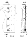
Fig. 2 in vergrößertem Maßstab einen Teilschnitt in Richtung des Pfeiles II inFig. 1 ; -
Fig.3 einen Schnitt A-A gemäßFig. 2 ; -
Fig. 4 in nochmals vergrößerter Darstellung das Detail Z inFig. 3 . - Gemäß den Zeichnungen ist ein Wärmetauseher 1, von dem in
Fig. 1 nur die eine Seite gezeigt ist, mit Seitenblechen 2 versehen. Die Seitenbleche 2 haben Bohrungen, in die Blindnietmuttern 3 eingenietet sind. - Mit den Seitenblechen 2 sind mittels Blindnieten 4 Blechstreifen 5 verbunden, die Bohrungen 6 aufweisen, deren Durchmesser kleiner als der größte Außendurchmesser der Blindnietmuttern 3 ist.
- Die Bohrungen 6 sind entsprechend dem gleichen Bohrbild wie Bohrungen 7 auf einer Trennwand 8 angeordnet. Die Bohrungen 7 haben jedoch einen größeren Durchmesser als der Außendurchmesser der Blindnietmuttern 3. Der Wärmetauscher 1 wird mittels in die Blindnietmuttern 3 eingeschraubten Schrauben 9 und Abdeckscheiben 10 an der Trennwand 8 befestigt.
- Wie insbesondere aus den
Fig. 3 und4 ersichtlich ist, kann die Blindnietmutter 3 nicht ausknöpfen, weil sie sich am Blechstreifen 5 abstützt. - Im Rahmen der Erfindung sind zahlreiche Abänderungen möglich. Insbesondere können, wie eingangs bereits ausgeführt wurde, die Blindnietmuttern 3 in den Blechstreifen 5 eingenietet werden, wobei der Blechstreifen 5 dann hinter dem Seitenblech 2 angeordnet ist.
Claims (3)
- Verfahren zur Befestigung eines mit Seitenblechen (2) versehenen Wärmetauschers (1) mittels Blindnietmuttern (3) und Schrauben (9) an einer mit Bohrungen (7) zum Durchstecken der Schrauben (9) versehenen Trennwand (8), dadurch gekennzeichnet, daß die Bohrungen (7) der Trennwand (8) mit einem Durchmesser hergestellt werden, der größer als der Außendurchmesser der Blindnietmuttern (3) ist und daß ein Blechstreifen (5) hergestellt wird, der das gleiche Bohrbild wie das Seitenblech (2) aufweist, aber mit Bohrungsdurchmessern kleiner als der Außendurchmesser der Blindnietmuttern (3), versehen ist, und daß der Blechstreifen (5) mit dem Seitenblech (2) verbunden wird, wonach Trennwand (8), Seitenblech (2) und Blechstreifen (5) mittels der Blindnietmuttern (3) und der Schrauben (9) derart miteinander verschraubt werden, daß die Blindnietmuttern (3) kopfseitig sich am Blechstreifen (5) oder am Seitenblech (2) abstützen.
- Anordnung, hergestellt nach dem Verfahren nach Anspruch 1, dadurch gekennzeichnet, daß, wenn die Blindnietmuttern (3) kopfseitig sich am Blechstreifen (5) abstützen, die Blindnietmuttern (3) in das Seitenblech (2) genietet sind und der Blechstreifen (5) zwischen dem Seitenblech (2) und der Trennwand (8) angeordnet ist.
- Anordnung hergestellt nach dem Verfahren nach Anspruch 1, dadurch gekennzeichnet, daß, wenn die Blindnietmuttern (3) kopfseitig sich am Seitenblech (2) abstützen, die Blindnietmuttern (3) in den Blechstreifen (5) genietet sind, der hinter dem Seitenblech (2) angeordnet ist.
Priority Applications (1)
| Application Number | Priority Date | Filing Date | Title |
|---|---|---|---|
| PL15450009T PL2916093T3 (pl) | 2014-03-06 | 2015-03-05 | Sposób mocowania wymiennika ciepła wyposażonego w blachy boczne |
Applications Claiming Priority (1)
| Application Number | Priority Date | Filing Date | Title |
|---|---|---|---|
| ATA160/2014A AT514805B1 (de) | 2014-03-06 | 2014-03-06 | Anordnung zur Befestigung eines mit Seitenblechen versehenen Wärmetauschers |
Publications (2)
| Publication Number | Publication Date |
|---|---|
| EP2916093A1 EP2916093A1 (de) | 2015-09-09 |
| EP2916093B1 true EP2916093B1 (de) | 2018-08-22 |
Family
ID=52780660
Family Applications (1)
| Application Number | Title | Priority Date | Filing Date |
|---|---|---|---|
| EP15450009.4A Active EP2916093B1 (de) | 2014-03-06 | 2015-03-05 | Verfahren zur Befestigung eines mit Seitenblechen versehenen Wärmetauschers |
Country Status (3)
| Country | Link |
|---|---|
| EP (1) | EP2916093B1 (de) |
| AT (1) | AT514805B1 (de) |
| PL (1) | PL2916093T3 (de) |
Family Cites Families (8)
| Publication number | Priority date | Publication date | Assignee | Title |
|---|---|---|---|---|
| GB536553A (en) * | 1940-04-24 | 1941-05-19 | Oliver Edwin Simmonds | Improvements relating to fastening devices incorporating nuts |
| BE636203A (de) * | 1962-08-16 | |||
| DE19927006C2 (de) * | 1999-06-09 | 2001-05-10 | Daimler Chrysler Ag | Fußboden für Fahrzeuge, insbesondere Schienenfahrzeuge zur Personenbeförderung |
| DE10126747C2 (de) * | 2001-05-31 | 2003-06-05 | Gesipa Blindniettechnik | Blindnietmutter und Befestigungseinheit |
| DE102004053851A1 (de) * | 2004-11-04 | 2006-05-11 | Behr Industry Gmbh & Co. Kg | Befestigungssystem, insbesondere für einen Wärmetauscher |
| FR2974606B1 (fr) * | 2011-04-29 | 2013-06-14 | Alex Grojean | Boulon a sertir en aveugle |
| FR2979401B1 (fr) * | 2011-08-26 | 2014-10-24 | Bollhoff Otalu Sa | Dispositif a sertir pour fixer un element en plastique, et installation mettant en oeuvre ledit dispositif |
| DE202013010302U1 (de) * | 2013-11-15 | 2013-12-16 | Bernd Pragst | Transparente Zugangsluke für ein Silo |
-
2014
- 2014-03-06 AT ATA160/2014A patent/AT514805B1/de active
-
2015
- 2015-03-05 PL PL15450009T patent/PL2916093T3/pl unknown
- 2015-03-05 EP EP15450009.4A patent/EP2916093B1/de active Active
Non-Patent Citations (1)
| Title |
|---|
| None * |
Also Published As
| Publication number | Publication date |
|---|---|
| EP2916093A1 (de) | 2015-09-09 |
| AT514805B1 (de) | 2015-04-15 |
| AT514805A4 (de) | 2015-04-15 |
| PL2916093T3 (pl) | 2019-03-29 |
Similar Documents
| Publication | Publication Date | Title |
|---|---|---|
| DE102012200845B4 (de) | Struktur zum Installieren einer Einpressmutter in eine Platte | |
| DE102013217633A1 (de) | Stanzniet und Verfahren zur Befestigung einzelner Bauteile aneinander, von denen mindestens ein Bauteil durch ein Werkstück aus Verbundmaterial gebildet ist | |
| DE102013006723A1 (de) | Hohlprofilträger für eine Tragvorrichtung zum Tragen von Werkzeugen, Werkstücken oder dergleichen, System zum Aufbauen einer derartigen Tragvorrichtung sowie Kreuzverbinder und Vorrichtung zur Befestigung eines Endeffektors an einem Grundrahmen an einer derartigen Tragvorrichtung | |
| DE102011055724A1 (de) | Nietbolzen | |
| DE102013016518A1 (de) | Dreidimensionaler Baukörper | |
| DE1212927B (de) | Spannelement zur Verbindung mehrerer uebereinanderliegender Bleche od. dgl., vorzugsweise zur Verbindung von Federschienen fuer den hydraulischen Grubenausbau | |
| EP3140174B1 (de) | Fahrzeug, insbesondere schienenfahrzeug, mit einer montageschiene | |
| AT514805B1 (de) | Anordnung zur Befestigung eines mit Seitenblechen versehenen Wärmetauschers | |
| DE102009011089A1 (de) | Verbindungsknotenanordnung für ein wenigstens zweidimensionales Tragwerk und Bausystem | |
| DE202013000832U1 (de) | Gitterboden und Auflagerahmen für Regale | |
| DE102013222050A1 (de) | Lageranordnung | |
| CH532726A (de) | Befestigungsvorrichtung | |
| DE2730838A1 (de) | Aufhaengekopf fuer laststrang-orientierte anschlagkettensysteme | |
| DE102009030769A1 (de) | Befestigungsanordnung | |
| EP3015655A1 (de) | Radscheibenanordnung mit Dichtblechen | |
| DE1910377C3 (de) | Platten-Nietverbindung | |
| DE102014118180A1 (de) | Baugruppe zur Lagerung eines Kotflügels in einem rohbauseitigen Träger bei einem Kraftfahrzeug | |
| DE102018127768A1 (de) | Beschlag sowie Befestigungsset | |
| DE711735C (de) | Blechverbindung | |
| DE102011001894A1 (de) | Verfahren zur Herstellung einer Spreizhülse, Spreizhülse und Baureihe von Spreizhülsen | |
| DE102015011553A1 (de) | Drehmomentschrauber | |
| DE102018128259A1 (de) | Mobiles gebäude, insbesondere tiny house | |
| DE102017130090A1 (de) | Vorrichtung sowie Verfahren zum Temperieren eines Raumes | |
| DE102015009376A1 (de) | Verstärkungselement für ein Bauteil eines Kraftfahrzeugs | |
| AT16045U1 (de) | Flächiger Verbund aus Holzelementen |
Legal Events
| Date | Code | Title | Description |
|---|---|---|---|
| PUAI | Public reference made under article 153(3) epc to a published international application that has entered the european phase |
Free format text: ORIGINAL CODE: 0009012 |
|
| AK | Designated contracting states |
Kind code of ref document: A1 Designated state(s): AL AT BE BG CH CY CZ DE DK EE ES FI FR GB GR HR HU IE IS IT LI LT LU LV MC MK MT NL NO PL PT RO RS SE SI SK SM TR |
|
| AX | Request for extension of the european patent |
Extension state: BA ME |
|
| 17P | Request for examination filed |
Effective date: 20150924 |
|
| RBV | Designated contracting states (corrected) |
Designated state(s): AL AT BE BG CH CY CZ DE DK EE ES FI FR GB GR HR HU IE IS IT LI LT LU LV MC MK MT NL NO PL PT RO RS SE SI SK SM TR |
|
| STAA | Information on the status of an ep patent application or granted ep patent |
Free format text: STATUS: EXAMINATION IS IN PROGRESS |
|
| 17Q | First examination report despatched |
Effective date: 20170706 |
|
| GRAP | Despatch of communication of intention to grant a patent |
Free format text: ORIGINAL CODE: EPIDOSNIGR1 |
|
| STAA | Information on the status of an ep patent application or granted ep patent |
Free format text: STATUS: GRANT OF PATENT IS INTENDED |
|
| INTG | Intention to grant announced |
Effective date: 20180320 |
|
| GRAS | Grant fee paid |
Free format text: ORIGINAL CODE: EPIDOSNIGR3 |
|
| GRAA | (expected) grant |
Free format text: ORIGINAL CODE: 0009210 |
|
| STAA | Information on the status of an ep patent application or granted ep patent |
Free format text: STATUS: THE PATENT HAS BEEN GRANTED |
|
| AK | Designated contracting states |
Kind code of ref document: B1 Designated state(s): AL AT BE BG CH CY CZ DE DK EE ES FI FR GB GR HR HU IE IS IT LI LT LU LV MC MK MT NL NO PL PT RO RS SE SI SK SM TR |
|
| REG | Reference to a national code |
Ref country code: GB Ref legal event code: FG4D Free format text: NOT ENGLISH |
|
| REG | Reference to a national code |
Ref country code: CH Ref legal event code: EP |
|
| REG | Reference to a national code |
Ref country code: AT Ref legal event code: REF Ref document number: 1032999 Country of ref document: AT Kind code of ref document: T Effective date: 20180915 |
|
| REG | Reference to a national code |
Ref country code: IE Ref legal event code: FG4D Free format text: LANGUAGE OF EP DOCUMENT: GERMAN |
|
| REG | Reference to a national code |
Ref country code: DE Ref legal event code: R096 Ref document number: 502015005542 Country of ref document: DE |
|
| REG | Reference to a national code |
Ref country code: DE Ref legal event code: R081 Ref document number: 502015005542 Country of ref document: DE Owner name: KIEPE ELECTRIC GES.M.B.H., AT Free format text: FORMER OWNER: VOSSLOH KIEPE GES.M.B.H., WIEN, AT |
|
| RAP2 | Party data changed (patent owner data changed or rights of a patent transferred) |
Owner name: KIEPE ELECTRIC GES.M.B.H. |
|
| REG | Reference to a national code |
Ref country code: NL Ref legal event code: MP Effective date: 20180822 |
|
| REG | Reference to a national code |
Ref country code: LT Ref legal event code: MG4D |
|
| REG | Reference to a national code |
Ref country code: AT Ref legal event code: HC Ref document number: 1032999 Country of ref document: AT Kind code of ref document: T Owner name: KIEPE ELECTRIC GES.M.B.H., AT Effective date: 20181119 |
|
| PG25 | Lapsed in a contracting state [announced via postgrant information from national office to epo] |
Ref country code: GR Free format text: LAPSE BECAUSE OF FAILURE TO SUBMIT A TRANSLATION OF THE DESCRIPTION OR TO PAY THE FEE WITHIN THE PRESCRIBED TIME-LIMIT Effective date: 20181123 Ref country code: NO Free format text: LAPSE BECAUSE OF FAILURE TO SUBMIT A TRANSLATION OF THE DESCRIPTION OR TO PAY THE FEE WITHIN THE PRESCRIBED TIME-LIMIT Effective date: 20181122 Ref country code: FI Free format text: LAPSE BECAUSE OF FAILURE TO SUBMIT A TRANSLATION OF THE DESCRIPTION OR TO PAY THE FEE WITHIN THE PRESCRIBED TIME-LIMIT Effective date: 20180822 Ref country code: LT Free format text: LAPSE BECAUSE OF FAILURE TO SUBMIT A TRANSLATION OF THE DESCRIPTION OR TO PAY THE FEE WITHIN THE PRESCRIBED TIME-LIMIT Effective date: 20180822 Ref country code: IS Free format text: LAPSE BECAUSE OF FAILURE TO SUBMIT A TRANSLATION OF THE DESCRIPTION OR TO PAY THE FEE WITHIN THE PRESCRIBED TIME-LIMIT Effective date: 20181222 Ref country code: RS Free format text: LAPSE BECAUSE OF FAILURE TO SUBMIT A TRANSLATION OF THE DESCRIPTION OR TO PAY THE FEE WITHIN THE PRESCRIBED TIME-LIMIT Effective date: 20180822 Ref country code: BG Free format text: LAPSE BECAUSE OF FAILURE TO SUBMIT A TRANSLATION OF THE DESCRIPTION OR TO PAY THE FEE WITHIN THE PRESCRIBED TIME-LIMIT Effective date: 20181122 Ref country code: NL Free format text: LAPSE BECAUSE OF FAILURE TO SUBMIT A TRANSLATION OF THE DESCRIPTION OR TO PAY THE FEE WITHIN THE PRESCRIBED TIME-LIMIT Effective date: 20180822 Ref country code: SE Free format text: LAPSE BECAUSE OF FAILURE TO SUBMIT A TRANSLATION OF THE DESCRIPTION OR TO PAY THE FEE WITHIN THE PRESCRIBED TIME-LIMIT Effective date: 20180822 |
|
| PG25 | Lapsed in a contracting state [announced via postgrant information from national office to epo] |
Ref country code: LV Free format text: LAPSE BECAUSE OF FAILURE TO SUBMIT A TRANSLATION OF THE DESCRIPTION OR TO PAY THE FEE WITHIN THE PRESCRIBED TIME-LIMIT Effective date: 20180822 Ref country code: AL Free format text: LAPSE BECAUSE OF FAILURE TO SUBMIT A TRANSLATION OF THE DESCRIPTION OR TO PAY THE FEE WITHIN THE PRESCRIBED TIME-LIMIT Effective date: 20180822 Ref country code: HR Free format text: LAPSE BECAUSE OF FAILURE TO SUBMIT A TRANSLATION OF THE DESCRIPTION OR TO PAY THE FEE WITHIN THE PRESCRIBED TIME-LIMIT Effective date: 20180822 |
|
| PG25 | Lapsed in a contracting state [announced via postgrant information from national office to epo] |
Ref country code: ES Free format text: LAPSE BECAUSE OF FAILURE TO SUBMIT A TRANSLATION OF THE DESCRIPTION OR TO PAY THE FEE WITHIN THE PRESCRIBED TIME-LIMIT Effective date: 20180822 Ref country code: RO Free format text: LAPSE BECAUSE OF FAILURE TO SUBMIT A TRANSLATION OF THE DESCRIPTION OR TO PAY THE FEE WITHIN THE PRESCRIBED TIME-LIMIT Effective date: 20180822 Ref country code: EE Free format text: LAPSE BECAUSE OF FAILURE TO SUBMIT A TRANSLATION OF THE DESCRIPTION OR TO PAY THE FEE WITHIN THE PRESCRIBED TIME-LIMIT Effective date: 20180822 |
|
| REG | Reference to a national code |
Ref country code: DE Ref legal event code: R097 Ref document number: 502015005542 Country of ref document: DE |
|
| PG25 | Lapsed in a contracting state [announced via postgrant information from national office to epo] |
Ref country code: SM Free format text: LAPSE BECAUSE OF FAILURE TO SUBMIT A TRANSLATION OF THE DESCRIPTION OR TO PAY THE FEE WITHIN THE PRESCRIBED TIME-LIMIT Effective date: 20180822 Ref country code: SK Free format text: LAPSE BECAUSE OF FAILURE TO SUBMIT A TRANSLATION OF THE DESCRIPTION OR TO PAY THE FEE WITHIN THE PRESCRIBED TIME-LIMIT Effective date: 20180822 Ref country code: DK Free format text: LAPSE BECAUSE OF FAILURE TO SUBMIT A TRANSLATION OF THE DESCRIPTION OR TO PAY THE FEE WITHIN THE PRESCRIBED TIME-LIMIT Effective date: 20180822 |
|
| PLBE | No opposition filed within time limit |
Free format text: ORIGINAL CODE: 0009261 |
|
| STAA | Information on the status of an ep patent application or granted ep patent |
Free format text: STATUS: NO OPPOSITION FILED WITHIN TIME LIMIT |
|
| 26N | No opposition filed |
Effective date: 20190523 |
|
| PG25 | Lapsed in a contracting state [announced via postgrant information from national office to epo] |
Ref country code: SI Free format text: LAPSE BECAUSE OF FAILURE TO SUBMIT A TRANSLATION OF THE DESCRIPTION OR TO PAY THE FEE WITHIN THE PRESCRIBED TIME-LIMIT Effective date: 20180822 |
|
| PG25 | Lapsed in a contracting state [announced via postgrant information from national office to epo] |
Ref country code: MC Free format text: LAPSE BECAUSE OF FAILURE TO SUBMIT A TRANSLATION OF THE DESCRIPTION OR TO PAY THE FEE WITHIN THE PRESCRIBED TIME-LIMIT Effective date: 20180822 |
|
| REG | Reference to a national code |
Ref country code: CH Ref legal event code: PL |
|
| GBPC | Gb: european patent ceased through non-payment of renewal fee |
Effective date: 20190305 |
|
| PG25 | Lapsed in a contracting state [announced via postgrant information from national office to epo] |
Ref country code: LU Free format text: LAPSE BECAUSE OF NON-PAYMENT OF DUE FEES Effective date: 20190305 |
|
| REG | Reference to a national code |
Ref country code: BE Ref legal event code: MM Effective date: 20190331 |
|
| PG25 | Lapsed in a contracting state [announced via postgrant information from national office to epo] |
Ref country code: IE Free format text: LAPSE BECAUSE OF NON-PAYMENT OF DUE FEES Effective date: 20190305 Ref country code: GB Free format text: LAPSE BECAUSE OF NON-PAYMENT OF DUE FEES Effective date: 20190305 Ref country code: LI Free format text: LAPSE BECAUSE OF NON-PAYMENT OF DUE FEES Effective date: 20190331 Ref country code: CH Free format text: LAPSE BECAUSE OF NON-PAYMENT OF DUE FEES Effective date: 20190331 |
|
| PG25 | Lapsed in a contracting state [announced via postgrant information from national office to epo] |
Ref country code: FR Free format text: LAPSE BECAUSE OF NON-PAYMENT OF DUE FEES Effective date: 20190331 Ref country code: BE Free format text: LAPSE BECAUSE OF NON-PAYMENT OF DUE FEES Effective date: 20190331 |
|
| PG25 | Lapsed in a contracting state [announced via postgrant information from national office to epo] |
Ref country code: TR Free format text: LAPSE BECAUSE OF FAILURE TO SUBMIT A TRANSLATION OF THE DESCRIPTION OR TO PAY THE FEE WITHIN THE PRESCRIBED TIME-LIMIT Effective date: 20180822 |
|
| PG25 | Lapsed in a contracting state [announced via postgrant information from national office to epo] |
Ref country code: PT Free format text: LAPSE BECAUSE OF FAILURE TO SUBMIT A TRANSLATION OF THE DESCRIPTION OR TO PAY THE FEE WITHIN THE PRESCRIBED TIME-LIMIT Effective date: 20181222 Ref country code: MT Free format text: LAPSE BECAUSE OF FAILURE TO SUBMIT A TRANSLATION OF THE DESCRIPTION OR TO PAY THE FEE WITHIN THE PRESCRIBED TIME-LIMIT Effective date: 20180822 |
|
| REG | Reference to a national code |
Ref country code: DE Ref legal event code: R082 Ref document number: 502015005542 Country of ref document: DE Representative=s name: REBLE & KESSELHUT PARTNERSCHAFTSGESELLSCHAFT V, DE |
|
| PG25 | Lapsed in a contracting state [announced via postgrant information from national office to epo] |
Ref country code: CY Free format text: LAPSE BECAUSE OF FAILURE TO SUBMIT A TRANSLATION OF THE DESCRIPTION OR TO PAY THE FEE WITHIN THE PRESCRIBED TIME-LIMIT Effective date: 20180822 |
|
| PG25 | Lapsed in a contracting state [announced via postgrant information from national office to epo] |
Ref country code: HU Free format text: LAPSE BECAUSE OF FAILURE TO SUBMIT A TRANSLATION OF THE DESCRIPTION OR TO PAY THE FEE WITHIN THE PRESCRIBED TIME-LIMIT; INVALID AB INITIO Effective date: 20150305 |
|
| PG25 | Lapsed in a contracting state [announced via postgrant information from national office to epo] |
Ref country code: MK Free format text: LAPSE BECAUSE OF FAILURE TO SUBMIT A TRANSLATION OF THE DESCRIPTION OR TO PAY THE FEE WITHIN THE PRESCRIBED TIME-LIMIT Effective date: 20180822 |
|
| P01 | Opt-out of the competence of the unified patent court (upc) registered |
Effective date: 20240215 |
|
| PGFP | Annual fee paid to national office [announced via postgrant information from national office to epo] |
Ref country code: DE Payment date: 20250327 Year of fee payment: 11 |
|
| PGFP | Annual fee paid to national office [announced via postgrant information from national office to epo] |
Ref country code: AT Payment date: 20250318 Year of fee payment: 11 |
|
| PGFP | Annual fee paid to national office [announced via postgrant information from national office to epo] |
Ref country code: PL Payment date: 20250211 Year of fee payment: 11 Ref country code: CZ Payment date: 20250217 Year of fee payment: 11 |
|
| PGFP | Annual fee paid to national office [announced via postgrant information from national office to epo] |
Ref country code: IT Payment date: 20250321 Year of fee payment: 11 |
|
| REG | Reference to a national code |
Ref country code: DE Ref legal event code: R082 Ref document number: 502015005542 Country of ref document: DE Representative=s name: KESSELHUT, WOLF, DIPL.-PHYS., DE |