EP2916452B1 - Procédé de commande de flux magnétique primaire - Google Patents
Procédé de commande de flux magnétique primaire Download PDFInfo
- Publication number
- EP2916452B1 EP2916452B1 EP13851084.7A EP13851084A EP2916452B1 EP 2916452 B1 EP2916452 B1 EP 2916452B1 EP 13851084 A EP13851084 A EP 13851084A EP 2916452 B1 EP2916452 B1 EP 2916452B1
- Authority
- EP
- European Patent Office
- Prior art keywords
- magnetic flux
- primary magnetic
- amplitude
- torque
- command value
- Prior art date
- Legal status (The legal status is an assumption and is not a legal conclusion. Google has not performed a legal analysis and makes no representation as to the accuracy of the status listed.)
- Active
Links
Images




Classifications
-
- H—ELECTRICITY
- H02—GENERATION; CONVERSION OR DISTRIBUTION OF ELECTRIC POWER
- H02P—CONTROL OR REGULATION OF ELECTRIC MOTORS, ELECTRIC GENERATORS OR DYNAMO-ELECTRIC CONVERTERS; CONTROLLING TRANSFORMERS, REACTORS OR CHOKE COILS
- H02P21/00—Arrangements or methods for the control of electric machines by vector control, e.g. by control of field orientation
-
- H—ELECTRICITY
- H02—GENERATION; CONVERSION OR DISTRIBUTION OF ELECTRIC POWER
- H02P—CONTROL OR REGULATION OF ELECTRIC MOTORS, ELECTRIC GENERATORS OR DYNAMO-ELECTRIC CONVERTERS; CONTROLLING TRANSFORMERS, REACTORS OR CHOKE COILS
- H02P21/00—Arrangements or methods for the control of electric machines by vector control, e.g. by control of field orientation
- H02P21/14—Estimation or adaptation of machine parameters, e.g. flux, current or voltage
- H02P21/141—Flux estimation
-
- H—ELECTRICITY
- H02—GENERATION; CONVERSION OR DISTRIBUTION OF ELECTRIC POWER
- H02P—CONTROL OR REGULATION OF ELECTRIC MOTORS, ELECTRIC GENERATORS OR DYNAMO-ELECTRIC CONVERTERS; CONTROLLING TRANSFORMERS, REACTORS OR CHOKE COILS
- H02P21/00—Arrangements or methods for the control of electric machines by vector control, e.g. by control of field orientation
- H02P21/06—Rotor flux based control involving the use of rotor position or rotor speed sensors
-
- H—ELECTRICITY
- H02—GENERATION; CONVERSION OR DISTRIBUTION OF ELECTRIC POWER
- H02P—CONTROL OR REGULATION OF ELECTRIC MOTORS, ELECTRIC GENERATORS OR DYNAMO-ELECTRIC CONVERTERS; CONTROLLING TRANSFORMERS, REACTORS OR CHOKE COILS
- H02P21/00—Arrangements or methods for the control of electric machines by vector control, e.g. by control of field orientation
- H02P21/14—Estimation or adaptation of machine parameters, e.g. flux, current or voltage
-
- H—ELECTRICITY
- H02—GENERATION; CONVERSION OR DISTRIBUTION OF ELECTRIC POWER
- H02P—CONTROL OR REGULATION OF ELECTRIC MOTORS, ELECTRIC GENERATORS OR DYNAMO-ELECTRIC CONVERTERS; CONTROLLING TRANSFORMERS, REACTORS OR CHOKE COILS
- H02P23/00—Arrangements or methods for the control of AC motors characterised by a control method other than vector control
- H02P23/14—Estimation or adaptation of motor parameters, e.g. rotor time constant, flux, speed, current or voltage
-
- H—ELECTRICITY
- H02—GENERATION; CONVERSION OR DISTRIBUTION OF ELECTRIC POWER
- H02P—CONTROL OR REGULATION OF ELECTRIC MOTORS, ELECTRIC GENERATORS OR DYNAMO-ELECTRIC CONVERTERS; CONTROLLING TRANSFORMERS, REACTORS OR CHOKE COILS
- H02P27/00—Arrangements or methods for the control of AC motors characterised by the kind of supply voltage
- H02P27/04—Arrangements or methods for the control of AC motors characterised by the kind of supply voltage using variable-frequency supply voltage, e.g. inverter or converter supply voltage
- H02P27/06—Arrangements or methods for the control of AC motors characterised by the kind of supply voltage using variable-frequency supply voltage, e.g. inverter or converter supply voltage using DC to AC converters or inverters
-
- H—ELECTRICITY
- H02—GENERATION; CONVERSION OR DISTRIBUTION OF ELECTRIC POWER
- H02P—CONTROL OR REGULATION OF ELECTRIC MOTORS, ELECTRIC GENERATORS OR DYNAMO-ELECTRIC CONVERTERS; CONTROLLING TRANSFORMERS, REACTORS OR CHOKE COILS
- H02P6/00—Arrangements for controlling synchronous motors or other dynamo-electric motors using electronic commutation dependent on the rotor position; Electronic commutators therefor
- H02P6/14—Electronic commutators
- H02P6/16—Circuit arrangements for detecting position
-
- Y—GENERAL TAGGING OF NEW TECHNOLOGICAL DEVELOPMENTS; GENERAL TAGGING OF CROSS-SECTIONAL TECHNOLOGIES SPANNING OVER SEVERAL SECTIONS OF THE IPC; TECHNICAL SUBJECTS COVERED BY FORMER USPC CROSS-REFERENCE ART COLLECTIONS [XRACs] AND DIGESTS
- Y02—TECHNOLOGIES OR APPLICATIONS FOR MITIGATION OR ADAPTATION AGAINST CLIMATE CHANGE
- Y02P—CLIMATE CHANGE MITIGATION TECHNOLOGIES IN THE PRODUCTION OR PROCESSING OF GOODS
- Y02P80/00—Climate change mitigation technologies for sector-wide applications
- Y02P80/10—Efficient use of energy, e.g. using compressed air or pressurized fluid as energy carrier
Definitions
- the present invention relates to a technique for controlling a synchronous motor including a field and an armature.
- the present invention relates to a technique for controlling a rotary electric motor based on a so-called primary magnetic flux, which is a synthesis of a field flux that the field generates and a magnetic flux of an armature reaction generated by an armature current flowing in an armature winding.
- the primary magnetic flux control is a technique for stably controlling the rotary electric motor by controlling the primary magnetic flux of the rotary electric motor in accordance with a command value thereof.
- a phase of a field flux ⁇ 0 is employed at a d axis in a rotating coordinate system
- a phase of a primary magnetic flux [ ⁇ 1] (this is treated as a vector having a direction and amplitude) is employed at a ⁇ axis in another rotating coordinate system
- a phase difference of the ⁇ axis with respect to the d axis is a load angle ⁇ .
- a ⁇ axis is employed at a 90-degree leading phase with respect to the ⁇ axis.
- a ⁇ c axis and a ⁇ c axis are defined as control axes in the rotating coordinate system which is employed in the control of the primary magnetic flux [ ⁇ 1].
- the ⁇ c axis and the yc axis correspond to the ⁇ axis and the ⁇ axis, respectively, and a phase difference of the ⁇ c axis with respect to the d axis is assumed as ⁇ c.
- a command value of the primary magnetic flux [ ⁇ 1] (hereinafter, referred to as a "primary magnetic flux command value”) [ ⁇ 1*] (this is treated as a vector having a direction and amplitude) has a positive value ⁇ * as a ⁇ c-axis component, and a ⁇ c-axis component is zero.
- the ⁇ c-axis component ⁇ 1 ⁇ c of the primary magnetic flux [ ⁇ 1] is equal to the positive value ⁇ * (this is also the amplitude of the primary magnetic flux command value [ ⁇ 1*]), and the phase difference ⁇ c is equal to the load angle ⁇ , and the ⁇ c axis is coincident with the ⁇ axis.
- control for example, of a voltage command value to be corrected is performed so that not only the ⁇ c-axis component ⁇ 1 ⁇ c of the primary magnetic flux [ ⁇ 1] should be made equal to the amplitude ⁇ * of the primary magnetic flux command value [ ⁇ 1*] but also a yc-axis component ⁇ 1 ⁇ c thereof should be zero.
- the phase difference ⁇ c is thereby coincident with the load angle ⁇ .
- the amplitude ⁇ of the primary magnetic flux [ ⁇ 1] is made equal to the amplitude ⁇ * of the command value [ ⁇ 1*], and the phase difference ⁇ c is made coincident with the load angle ⁇ , whereby a torque T of the rotary electric motor can be controlled in proportion to the yc-axis component iyc of the amplitude ia of the armature current independently of a rotation angle velocity.
- the control is performed on the assumption that the amplitude ⁇ * is constant.
- Non-Patent Document 6 the ⁇ axis and the ⁇ axis are exchanged and employed, as compared with those in the following other prior art documents.
- a drive controller has a controlling means which incorporates means for calculating a magnetic flux command from a basic torque command, for calculating a torque current command, exciting current command and slip frequency, and for operating vector calculation.
- the electric vehicle drive controller drives the induction motor.
- Patent Document 4 describes a synchronous machine control apparatus which can produce a torque level as close as possible to a desired torque command level while considering limitations on an output current of a power conversion unit.
- a synchronous machine control apparatus includes a torque current command generator including a torque current calculator for calculating a torque current command i ⁇ ** from a torque command ⁇ * and a flux command ⁇ *, a torque current limit generator for generating a maximum torque current command value i ⁇ *max that can be generated based on a magnetizing current command i ⁇ * and a current limit value imax, and a limiter for imposing limitations on i ⁇ ** based on i ⁇ * max, a flux command generator for calculating the flux command ⁇ * based on i ⁇ * fed from the torque current command generator, a flux calculator for calculating an interlinked armature flux feedback value
- the present invention has been achieved in light of the above-described points, and an object thereof is to provide a technique for properly controlling a current phase by changing a primary magnetic flux command value in accordance with a torque in primary magnetic field control, and driving a rotary electric motor at an efficient operating point in accordance with the torque.
- a primary magnetic flux control method is defined by claim 1 and a method including: setting a primary magnetic flux command value ([ ⁇ 1*]), which is a command value of a primary magnetic flux ([ ⁇ 1]), on a rotary electric motor including an armature having an armature winding, and a rotor which is a field rotating relatively to the armature; and controlling the primary magnetic flux in accordance with the primary magnetic flux command value.
- the primary magnetic flux is a synthesis of a field flux ( ⁇ 0) that the field generates and a magnetic flux ([ ⁇ a]: id ⁇ Ld, iq ⁇ Lq) of an armature reaction generated by an armature current (ia) flowing in the armature.
- the primary magnetic flux command value is changed in accordance with a torque (T) of the rotary electric motor to control a current phase ( ⁇ ) of the armature current with respect to a q axis that advances by ⁇ /2 with respect to a d axis in phase with the field flux ( ⁇ 0) to be a desired phase in accordance with the torque.
- the amplitude ( ⁇ 0(T)) of the primary magnetic flux that minimizes the armature current is set as the amplitude ( ⁇ *) of the primary magnetic flux command value ([ ⁇ 1*]) in accordance with the torque.
- changing the primary magnetic flux command value in accordance with the torque enables the current phase to be properly controlled, and the rotary electric motor to be driven at an efficient operating point in accordance with the torque.
- the maximum torque/current control can be implemented.
- a rotary electric motor includes an armature having an armature winding, and a rotor which is a field rotating relatively to the armature.
- the rotary electric motor is provided with a permanent magnet or a field winding that generates a field flux.
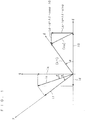
- Figs. 1 and 2 are vector diagrams each for describing primary magnetic field control.
- a ⁇ c- ⁇ c coordinate system which is a leading phase with respect to a d-q coordinate system (a d axis is in phase with a field flux ⁇ 0, and a q axis is in 90-degree leading phase with respect to the d axis) which employs a phase of the field flux ⁇ 0 (i.e. with the rotation of a rotor) as a reference, by a phase difference ⁇ c.
- a voltage to be applied to the rotary electric motor is adjusted so that a ⁇ c axis should be coincident with a ⁇ axis, which is in phase with the primary magnetic flux.
- Fig. 1 shows a case where the phase difference ⁇ c is coincident with a load angle ⁇ .
- a magnetic flux [ ⁇ a] (this is treated as a vector having a direction and amplitude) of an armature reaction is a synthesis of a magnetic flux Lq ⁇ iq in a q-axis positive direction and a magnetic flux Ld ⁇ id in a d-axis negative direction.
- a primary magnetic flux [ ⁇ 1] is a synthesis of the magnetic flux [ ⁇ a] and the field flux ⁇ 0 and takes a positive value ⁇ (this is coincident with the amplitude ⁇ * of a primary magnetic flux command value) in the ⁇ axis.
- a phase thereof leads with respect to the q axis by a current phase ⁇ , and the amplitude thereof ia can be decomposed into a q-axis component iq and a d-axis component id.
- the amplitude ia can be decomposed into a ⁇ c-axis component i ⁇ c and a ⁇ c-axis component i ⁇ c.
- Fig. 1 a case where a ⁇ c axis is coincident with a ⁇ axis is shown, and thus, a ⁇ -axis component iy corresponding to the ⁇ c-axis component i ⁇ c is shown.
- a component corresponding to the ⁇ c-axis component i ⁇ c is omitted in Fig. 1
- the q-axis component iq and the d-axis component id are omitted in Fig. 2 .
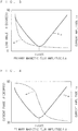
- Fig. 3 is a graph showing relationships between the positive value ⁇ , which is the amplitude of the primary magnetic flux [ ⁇ 1], and the amplitude ia of the armature current and the load angle ⁇ when the torque T is kept at a certain constant value. It can be understood that the amplitude ia has a local minimum value with respect to the positive value ⁇ .
- the primary magnetic field control is performed, using the above-described positive value ⁇ that gives the above-described local minimum value of the amplitude ia (this is indicated as a value ⁇ 0(T)), whereby maximum torque/current control can be implemented.
- the value ⁇ 0(T) takes various values, depending on the torque T.
- the relationship between the amplitude ⁇ of the primary magnetic flux and the amplitude ia of the armature current is found in advance, whereby the value ⁇ 0(T) obtained in accordance with the torque can be employed as the amplitude ⁇ * of the primary magnetic flux command value. This enables the maximum torque/current control to be implemented in the primary magnetic flux control.
- the primary magnetic flux command value [ ⁇ 1*] is changed in accordance with the torque T to perform the primary magnetic flux control, whereby the current phase ⁇ can be controlled so as to be the desired phase in accordance with the torque.
- the primary magnetic flux control with the amplitude ⁇ * of the primary magnetic flux command value [ ⁇ 1*] constant is performed, the rotary electric motor is driven at an inefficient operating point with respect to the torque T in some cases.
- changing the amplitude ⁇ * in accordance with the torque T enables the current phase ⁇ to be properly controlled, and the rotary electric motor to be driven at an efficient operating point in accordance with the torque T.
- FIG. 5 is a block diagram showing a configuration to obtain the above-described amplitude ⁇ *.
- a primary magnetic flux command value setting unit 1 stores relationships among the amplitude ⁇ of the primary magnetic flux [ ⁇ 1], the amplitude ia of the armature current, and the torque T of the rotary electric motor.
- the value ⁇ 0(T) that minimizes the amplitude ia is outputted as the amplitude ⁇ * of the primary magnetic flux command value [ ⁇ 1*] in accordance with the torque T.
- Fig. 5 an image is drawn in which the relationships between the amplitude ia and the value ⁇ 0(T) shown in Figs. 3 and 4 are stored with respect to the various torques T in the primary magnetic flux command value setting unit 1.
- T a detected value
- T ⁇ an estimated value T ⁇
- the estimated value T ⁇ is found by the following expression (3) with reference to Fig. 2 .
- T ⁇ n ⁇ 1 ⁇ c ⁇ i ⁇ c ⁇ ⁇ 1 ⁇ c ⁇ i ⁇ c
- the estimated value T ⁇ may be found by the following expression (4).
- T ⁇ n ⁇ ⁇ ⁇ ⁇ ⁇ i ⁇ c
- Fig. 6 is a block diagram showing a technique for finding, from the amplitude ⁇ *[n-1] of the primary magnetic flux command value [ ⁇ 1*] at certain control timing, the amplitude ⁇ *[n] of the primary magnetic flux command value [ ⁇ 1*] at next control timing.
- the amplitude ⁇ * that minimizes the amplitude ia is found, and the same method as a so-called "hill-climbing method" in which a parameter is changed to find a local minimum value of a control target value is used.
- an increment generator 2 has the change amount ⁇ and the difference ⁇ ia inputted to output ⁇ ⁇ g( ⁇ ia), and an adder adds ⁇ ⁇ g( ⁇ ia) to the amplitude ⁇ *[n-1] to find the amplitude ⁇ *[n].
- a function g(Q) takes a value (-1) when a value Q is positive, and takes a value 1 when the value Q is negative.
- Figs. 7 to 9 are graphs each showing a relationship between the torque T and the armature current at an operating point where the maximum torque/current is implemented.
- Fig. 7 is a graph showing a relationship between the torque T and the ⁇ -axis component iy of the amplitude ia
- Fig. 8 is a graph showing a relationship between the torque T and the ⁇ -axis component i ⁇ of the amplitude ia
- Fig. 9 is a graph showing a relationship between the torque T and the amplitude ia.
- Fig. 10 is a graph showing a relationship between the torque T and the load angle ⁇ at the operating point where the maximum torque/current is implemented.
- the graphs shown in Figs. 7 to 10 may be found from the expressions (1) and (2), or may be experimentally found.
- the amplitude ia can be grasped as one relevant index.
- Fig. 11 is a block diagram showing a technique for outputting the value ⁇ 0(T) corresponding to each of the ⁇ c-axis component i ⁇ c, the ⁇ c-axis component i ⁇ c, the amplitude ia, and the phase difference ⁇ c as the amplitude ⁇ *.
- a primary magnetic flux command value setting unit 4 has a torque estimating unit 3 and a primary magnetic flux command value setting unit 1.
- the torque estimating unit 3 sets a torque estimated value Te, based on ⁇ c-axis component iyc, the ⁇ c-axis component i ⁇ c (or further, the amplitude ia) or the phase difference ⁇ c.
- the torque estimated value Te is not the estimated value T ⁇ obtained by the expressions (3) and (4), but an estimated value of the torque T estimated from the expressions (1) and (2), or Figs. 7 to 10 .
- Fig. 12 illustrates a configuration in which a filter 5 is provided at a previous stage of the primary magnetic flux command value setting unit 1.
- Fig. 13 illustrates a configuration in which the filter 5 is provided at a previous stage of the primary magnetic flux command value setting unit 4.
- the filter 5 functions as a low-pass filter. Based on the torque T obtained by processing through the low-pass filter, setting the primary magnetic flux command value suppresses rapid change thereof. This can reduce influence on the primary magnetic flux control itself by setting the amplitude ⁇ * in each torque T (or each estimated value Te thereof), or in each ⁇ c-axis component i ⁇ c and ⁇ c-axis component i ⁇ c or in each phase difference ⁇ c.
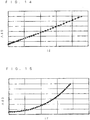
- the primary magnetic flux command value setting unit 4 shown in Fig. 11 is not necessarily required to have the torque estimating unit 3 and the primary magnetic flux command value setting unit 1. It is rather desirable to experimentally obtain a relationship between the ⁇ -axis component i ⁇ and the value ⁇ 0 (see Fig. 14 ) and a relationship between the ⁇ -axis component i ⁇ and the value ⁇ 0 (see Fig. 15 ) and to hold the same by formularization or as a table (or a map). This is because the torque estimated value Te need not be found once.
- the value ⁇ 0(T) may be the primary magnetic flux [ ⁇ 1] that provides minimum electric power/torque in place of the amplitude of the primary magnetic flux [ ⁇ 1] that provides the maximum torque/current.
- the amplitude ⁇ * taking the value ⁇ 0(T) is decided and the primary magnetic flux control is performed, the current phase ⁇ to obtain maximum efficiency is properly controlled without need for performing anew a calculation such as the current vector control.
- the primary magnetic flux that minimizes the loss is set as the primary magnetic flux command value in accordance with the torque T and the rotation velocity to perform the primary magnetic flux control, which can implement maximum efficiency control.
- Fig. 16 is a graph showing the loss with respect to the amplitude ⁇ of the primary magnetic flux [ ⁇ 1] when the torque T and the rotation velocity of the rotary electric motor are constant.
- Curves G1, G2 indicate copper loss, and a sum of the copper loss and iron loss of the rotary electric motor, respectively. Since the copper loss is proportional to the square of the current flowing the rotary electric motor, the primary magnetic flux that provides a minimum value of the curve G1 can be employed as the value ⁇ 0(T) in the first example.
- the amplitude of the primary magnetic flux [ ⁇ 1] that provides a minimum value of the curve G2 is found as a value ⁇ 1(T), and this is employed as the amplitude ⁇ * of the primary magnetic flux command [ ⁇ 1*].
- An increment generator 6 has the change amount ⁇ and the difference ⁇ P inputted to output ⁇ ⁇ g( ⁇ P), and an adder 7 adds ⁇ ⁇ g( ⁇ P) to the amplitude ⁇ * [n-1] to find the amplitude A ⁇ *[n].
- a function g is as described above.
- a filter may be used to remove components in the vicinity of a control frequency of the primary magnetic flux control of the torque T (or the estimated value thereof Te) and to set the amplitude ⁇ *.
- a table (or a map) of these values may be created.
- the read value may be set as the primary magnetic flux command value.
- the rotation velocity may be a value of an electrical angle or a value of a mechanical angle. Since in the steady state, velocities of the control axes (the ⁇ c axis and the ⁇ c axis) and a velocity command (of an electrical angle) are coincident with the rotation velocity, these may be substituted for the rotation velocity.
- a period when the amplitude ⁇ * is updated may be delayed with respect to a control period of the primary magnetic flux control. This can suppress interference between the setting of the primary magnetic flux command value [ ⁇ 1*] and the primary magnetic flux control.
- the amplitude ⁇ * is updated only when velocity pulsation falls in a predetermined range without updating apart from it, whereby the primary magnetic flux control can be stably executed.
- the primary magnetic flux command value [ ⁇ 1*] in terms of difficulty of impairment of stability of the primary magnetic flux control even if the primary magnetic flux command value [ ⁇ 1*] changes, it is desirable that the primary magnetic flux command value [ ⁇ 1*] is not changed in a transition period of the primary magnetic flux control based on the primary magnetic flux command value [ ⁇ 1*], but is updated in a state where the primary magnetic flux control is stable.
Landscapes
- Engineering & Computer Science (AREA)
- Power Engineering (AREA)
- Control Of Ac Motors In General (AREA)
Claims (3)
- Procédé de commande de flux magnétique primaire comprenant :le réglage d'une valeur de commande de flux magnétique primaire ([Λ1*]), qui est une valeur de commande d'un flux magnétique primaire ([λ1]), sur un moteur électrique rotatif incluant un induit présentant un bobinage d'induit, et un rotor qui présente un champ tournant par rapport audit induit ; etla commande dudit flux magnétique primaire conformément à ladite valeur de commande de flux magnétique primaire, ledit flux magnétique primaire étant une synthèse d'un flux de champ (Λ0) que ledit champ génère et d'un flux magnétique ([λa]:id•Ld, iq•Lq) d'une réaction d'induit générée par un courant d'induit (ia) s'écoulant dans ledit induit, etle changement de ladite valeur de commande de flux magnétique primaire conformément à un couple (T) dudit moteur électrique rotatif pour commander une phase de courant (β) dudit courant d'induit par rapport à un axe q qui est en avance de π/2 par rapport à un axe d en phase avec ledit flux de champ (Λ0) pour être une phase souhaitée conformément audit couple,caractérisé en ce quesur la base de relations entre ledit flux magnétique primaire ([λ1]), ladite perte dudit moteur électrique rotatif et ledit couple (T) et d'une vitesse de rotation dudit moteur électrique rotatif, ledit flux magnétique primaire ([λ1]) qui minimise ladite perte est réglé comme dite valeur de commande de flux magnétique primaire ([Λ1*]) conformément audit couple et à ladite vitesse de rotation.
- Procédé de commande de flux magnétique primaire selon la revendication 1, dans lequel une période où ladite valeur de commande de flux magnétique primaire est mise à jour est différente d'une période de commande dudit flux magnétique primaire sur la base de ladite valeur de commande de flux magnétique primaire.
- Procédé de commande de flux magnétique primaire selon la revendication 1 ou 2, dans lequel ladite valeur de commande de flux magnétique primaire n'est pas modifiée dans une période de transition de la commande dudit flux magnétique primaire sur la base de ladite valeur de commande de flux magnétique primaire, mais est mise à jour dans un état où ladite commande est stable.
Applications Claiming Priority (2)
| Application Number | Priority Date | Filing Date | Title |
|---|---|---|---|
| JP2012240326A JP5556875B2 (ja) | 2012-10-31 | 2012-10-31 | 一次磁束制御方法 |
| PCT/JP2013/077365 WO2014069188A1 (fr) | 2012-10-31 | 2013-10-08 | Procédé de commande de flux magnétique primaire |
Publications (3)
| Publication Number | Publication Date |
|---|---|
| EP2916452A1 EP2916452A1 (fr) | 2015-09-09 |
| EP2916452A4 EP2916452A4 (fr) | 2016-09-28 |
| EP2916452B1 true EP2916452B1 (fr) | 2021-02-24 |
Family
ID=50627103
Family Applications (1)
| Application Number | Title | Priority Date | Filing Date |
|---|---|---|---|
| EP13851084.7A Active EP2916452B1 (fr) | 2012-10-31 | 2013-10-08 | Procédé de commande de flux magnétique primaire |
Country Status (10)
| Country | Link |
|---|---|
| US (1) | US10110150B2 (fr) |
| EP (1) | EP2916452B1 (fr) |
| JP (1) | JP5556875B2 (fr) |
| KR (1) | KR101681438B1 (fr) |
| CN (1) | CN104756396B (fr) |
| AU (1) | AU2013339484B2 (fr) |
| BR (1) | BR112015009647B1 (fr) |
| ES (1) | ES2860500T3 (fr) |
| RU (1) | RU2606637C2 (fr) |
| WO (1) | WO2014069188A1 (fr) |
Families Citing this family (8)
| Publication number | Priority date | Publication date | Assignee | Title |
|---|---|---|---|---|
| JP5862691B2 (ja) * | 2014-01-10 | 2016-02-16 | ダイキン工業株式会社 | 電動機駆動装置の制御装置および電動機駆動システム |
| JP6582393B2 (ja) * | 2014-11-06 | 2019-10-02 | ダイキン工業株式会社 | 電動機駆動装置の制御装置 |
| JP6405987B2 (ja) * | 2014-12-22 | 2018-10-17 | ダイキン工業株式会社 | インバータの制御装置 |
| JP6135713B2 (ja) | 2015-06-18 | 2017-05-31 | 株式会社安川電機 | モータ制御装置、磁束指令の生成装置および磁束指令の生成方法 |
| JP6103125B1 (ja) | 2015-10-29 | 2017-03-29 | ダイキン工業株式会社 | 速度指令補正装置、一次磁束指令生成装置 |
| KR102431317B1 (ko) * | 2015-12-14 | 2022-08-09 | 현대모비스 주식회사 | 차량용 모터 제어장치 및 방법 |
| KR102548679B1 (ko) * | 2015-12-14 | 2023-06-27 | 현대모비스 주식회사 | 차량용 모터 제어 장치 및 이를 이용한 전류 지령 생성 방법 |
| CN108063569B (zh) * | 2017-11-22 | 2019-11-12 | 南京航空航天大学 | 一种永磁电机最优工作点的快速求解方法 |
Citations (1)
| Publication number | Priority date | Publication date | Assignee | Title |
|---|---|---|---|---|
| JPH10243699A (ja) * | 1997-02-27 | 1998-09-11 | Fuji Electric Co Ltd | 同期電動機の制御装置 |
Family Cites Families (17)
| Publication number | Priority date | Publication date | Assignee | Title |
|---|---|---|---|---|
| US4814677A (en) * | 1987-12-14 | 1989-03-21 | General Electric Company | Field orientation control of a permanent magnet motor |
| JPH03150090A (ja) * | 1989-11-02 | 1991-06-26 | Fanuc Ltd | 主軸モータの制御方式 |
| JPH0491693A (ja) * | 1990-08-03 | 1992-03-25 | Matsushita Electric Ind Co Ltd | ブラシレスモータの駆動方法 |
| JP2755011B2 (ja) * | 1992-02-13 | 1998-05-20 | 三菱電機株式会社 | モータ駆動制御装置 |
| JP3262253B2 (ja) * | 1995-02-22 | 2002-03-04 | 株式会社日立製作所 | 電気車用駆動制御装置及び制御方法 |
| RU2092967C1 (ru) * | 1995-07-27 | 1997-10-10 | Новосибирский государственный технический университет | Электропривод с синхронным двигателем |
| JPH09327200A (ja) * | 1996-06-06 | 1997-12-16 | Hitachi Ltd | 同期電動機の制御装置 |
| JP2000032799A (ja) * | 1998-07-07 | 2000-01-28 | Hitachi Ltd | 回転電機の制御装置及び制御方法 |
| JP3716670B2 (ja) * | 1998-09-29 | 2005-11-16 | 三菱電機株式会社 | 誘導電動機の制御装置 |
| JP3672761B2 (ja) * | 1999-03-04 | 2005-07-20 | 譲 常広 | 同期電動機駆動装置 |
| JP3637897B2 (ja) * | 2002-02-28 | 2005-04-13 | 三菱電機株式会社 | 同期電動機駆動装置、インバータ装置、同期電動機の制御方法 |
| JP4531751B2 (ja) * | 2004-05-14 | 2010-08-25 | 三菱電機株式会社 | 同期機制御装置 |
| JP2006230169A (ja) * | 2005-02-21 | 2006-08-31 | Toshiba Corp | 同期機の制御装置 |
| CN101529714B (zh) * | 2006-10-19 | 2012-11-21 | 三菱电机株式会社 | 永磁同步电动机的矢量控制装置 |
| JP5104239B2 (ja) * | 2007-11-13 | 2012-12-19 | 富士電機株式会社 | 永久磁石形同期電動機の制御装置 |
| CN102017395B (zh) * | 2008-04-28 | 2014-08-06 | 大金工业株式会社 | 直交流转换器控制装置及功率转换装置 |
| KR101628385B1 (ko) * | 2010-03-31 | 2016-06-08 | 현대자동차주식회사 | 영구자석 동기모터의 제어방법 |
-
2012
- 2012-10-31 JP JP2012240326A patent/JP5556875B2/ja active Active
-
2013
- 2013-10-08 WO PCT/JP2013/077365 patent/WO2014069188A1/fr not_active Ceased
- 2013-10-08 ES ES13851084T patent/ES2860500T3/es active Active
- 2013-10-08 AU AU2013339484A patent/AU2013339484B2/en active Active
- 2013-10-08 CN CN201380056687.4A patent/CN104756396B/zh active Active
- 2013-10-08 US US14/439,251 patent/US10110150B2/en active Active
- 2013-10-08 EP EP13851084.7A patent/EP2916452B1/fr active Active
- 2013-10-08 RU RU2015120609A patent/RU2606637C2/ru active
- 2013-10-08 BR BR112015009647-6A patent/BR112015009647B1/pt active IP Right Grant
- 2013-10-08 KR KR1020157009707A patent/KR101681438B1/ko not_active Expired - Fee Related
Patent Citations (1)
| Publication number | Priority date | Publication date | Assignee | Title |
|---|---|---|---|---|
| JPH10243699A (ja) * | 1997-02-27 | 1998-09-11 | Fuji Electric Co Ltd | 同期電動機の制御装置 |
Also Published As
| Publication number | Publication date |
|---|---|
| JP5556875B2 (ja) | 2014-07-23 |
| BR112015009647B1 (pt) | 2021-07-27 |
| JP2014090626A (ja) | 2014-05-15 |
| CN104756396A (zh) | 2015-07-01 |
| CN104756396B (zh) | 2017-06-23 |
| KR101681438B1 (ko) | 2016-11-30 |
| KR20150058362A (ko) | 2015-05-28 |
| US10110150B2 (en) | 2018-10-23 |
| AU2013339484B2 (en) | 2016-01-07 |
| ES2860500T3 (es) | 2021-10-05 |
| EP2916452A4 (fr) | 2016-09-28 |
| RU2015120609A (ru) | 2016-12-20 |
| US20150311846A1 (en) | 2015-10-29 |
| AU2013339484A1 (en) | 2015-05-14 |
| RU2606637C2 (ru) | 2017-01-10 |
| EP2916452A1 (fr) | 2015-09-09 |
| BR112015009647A2 (pt) | 2017-07-04 |
| WO2014069188A1 (fr) | 2014-05-08 |
Similar Documents
| Publication | Publication Date | Title |
|---|---|---|
| EP2916452B1 (fr) | Procédé de commande de flux magnétique primaire | |
| EP3252941B1 (fr) | Appareil de commande d'onduleur et système d'entraînement de moteur | |
| US9621093B2 (en) | Motor control device | |
| CN107710594B (zh) | 交流旋转电机的控制装置及电动助力转向的控制装置 | |
| EP2892147B1 (fr) | Dispositif de commande de moteur électrique | |
| JP6075090B2 (ja) | モータ制御装置 | |
| KR101339653B1 (ko) | 동기기의 위치 센서리스 제어 장치 | |
| WO2016121237A1 (fr) | Dispositif de commande d'onduleur et système d'attaque de moteur | |
| US9602035B2 (en) | Driving apparatus for electric motor | |
| JP6115250B2 (ja) | モータ制御装置 | |
| JP6115251B2 (ja) | モータ制御装置 | |
| EP3128668B1 (fr) | Dispositif d'entraînement d'appareil électrique | |
| JP4402600B2 (ja) | 同期電動機の駆動システム及び同期電動機の駆動方法 | |
| JP2016163515A (ja) | 同期機制御装置及び駆動システム |
Legal Events
| Date | Code | Title | Description |
|---|---|---|---|
| PUAI | Public reference made under article 153(3) epc to a published international application that has entered the european phase |
Free format text: ORIGINAL CODE: 0009012 |
|
| 17P | Request for examination filed |
Effective date: 20150427 |
|
| AK | Designated contracting states |
Kind code of ref document: A1 Designated state(s): AL AT BE BG CH CY CZ DE DK EE ES FI FR GB GR HR HU IE IS IT LI LT LU LV MC MK MT NL NO PL PT RO RS SE SI SK SM TR |
|
| AX | Request for extension of the european patent |
Extension state: BA ME |
|
| DAX | Request for extension of the european patent (deleted) | ||
| REG | Reference to a national code |
Ref country code: DE Ref legal event code: R079 Ref document number: 602013075917 Country of ref document: DE Free format text: PREVIOUS MAIN CLASS: H02P0021000000 Ipc: H02P0021140000 |
|
| RA4 | Supplementary search report drawn up and despatched (corrected) |
Effective date: 20160829 |
|
| RIC1 | Information provided on ipc code assigned before grant |
Ipc: H02P 27/04 20060101ALI20160823BHEP Ipc: H02P 21/06 20060101ALI20160823BHEP Ipc: H02P 21/14 20060101AFI20160823BHEP Ipc: H02P 27/06 20060101ALI20160823BHEP Ipc: H02P 23/14 20060101ALI20160823BHEP |
|
| STAA | Information on the status of an ep patent application or granted ep patent |
Free format text: STATUS: EXAMINATION IS IN PROGRESS |
|
| 17Q | First examination report despatched |
Effective date: 20180920 |
|
| GRAP | Despatch of communication of intention to grant a patent |
Free format text: ORIGINAL CODE: EPIDOSNIGR1 |
|
| STAA | Information on the status of an ep patent application or granted ep patent |
Free format text: STATUS: GRANT OF PATENT IS INTENDED |
|
| INTG | Intention to grant announced |
Effective date: 20201029 |
|
| GRAS | Grant fee paid |
Free format text: ORIGINAL CODE: EPIDOSNIGR3 |
|
| GRAA | (expected) grant |
Free format text: ORIGINAL CODE: 0009210 |
|
| STAA | Information on the status of an ep patent application or granted ep patent |
Free format text: STATUS: THE PATENT HAS BEEN GRANTED |
|
| AK | Designated contracting states |
Kind code of ref document: B1 Designated state(s): AL AT BE BG CH CY CZ DE DK EE ES FI FR GB GR HR HU IE IS IT LI LT LU LV MC MK MT NL NO PL PT RO RS SE SI SK SM TR |
|
| REG | Reference to a national code |
Ref country code: GB Ref legal event code: FG4D |
|
| REG | Reference to a national code |
Ref country code: CH Ref legal event code: EP |
|
| REG | Reference to a national code |
Ref country code: AT Ref legal event code: REF Ref document number: 1365756 Country of ref document: AT Kind code of ref document: T Effective date: 20210315 |
|
| REG | Reference to a national code |
Ref country code: IE Ref legal event code: FG4D |
|
| REG | Reference to a national code |
Ref country code: DE Ref legal event code: R096 Ref document number: 602013075917 Country of ref document: DE |
|
| REG | Reference to a national code |
Ref country code: LT Ref legal event code: MG9D |
|
| REG | Reference to a national code |
Ref country code: NL Ref legal event code: MP Effective date: 20210224 |
|
| PG25 | Lapsed in a contracting state [announced via postgrant information from national office to epo] |
Ref country code: NO Free format text: LAPSE BECAUSE OF FAILURE TO SUBMIT A TRANSLATION OF THE DESCRIPTION OR TO PAY THE FEE WITHIN THE PRESCRIBED TIME-LIMIT Effective date: 20210524 Ref country code: BG Free format text: LAPSE BECAUSE OF FAILURE TO SUBMIT A TRANSLATION OF THE DESCRIPTION OR TO PAY THE FEE WITHIN THE PRESCRIBED TIME-LIMIT Effective date: 20210524 Ref country code: GR Free format text: LAPSE BECAUSE OF FAILURE TO SUBMIT A TRANSLATION OF THE DESCRIPTION OR TO PAY THE FEE WITHIN THE PRESCRIBED TIME-LIMIT Effective date: 20210525 Ref country code: HR Free format text: LAPSE BECAUSE OF FAILURE TO SUBMIT A TRANSLATION OF THE DESCRIPTION OR TO PAY THE FEE WITHIN THE PRESCRIBED TIME-LIMIT Effective date: 20210224 Ref country code: FI Free format text: LAPSE BECAUSE OF FAILURE TO SUBMIT A TRANSLATION OF THE DESCRIPTION OR TO PAY THE FEE WITHIN THE PRESCRIBED TIME-LIMIT Effective date: 20210224 Ref country code: PT Free format text: LAPSE BECAUSE OF FAILURE TO SUBMIT A TRANSLATION OF THE DESCRIPTION OR TO PAY THE FEE WITHIN THE PRESCRIBED TIME-LIMIT Effective date: 20210624 Ref country code: LT Free format text: LAPSE BECAUSE OF FAILURE TO SUBMIT A TRANSLATION OF THE DESCRIPTION OR TO PAY THE FEE WITHIN THE PRESCRIBED TIME-LIMIT Effective date: 20210224 |
|
| REG | Reference to a national code |
Ref country code: AT Ref legal event code: MK05 Ref document number: 1365756 Country of ref document: AT Kind code of ref document: T Effective date: 20210224 |
|
| PG25 | Lapsed in a contracting state [announced via postgrant information from national office to epo] |
Ref country code: RS Free format text: LAPSE BECAUSE OF FAILURE TO SUBMIT A TRANSLATION OF THE DESCRIPTION OR TO PAY THE FEE WITHIN THE PRESCRIBED TIME-LIMIT Effective date: 20210224 Ref country code: NL Free format text: LAPSE BECAUSE OF FAILURE TO SUBMIT A TRANSLATION OF THE DESCRIPTION OR TO PAY THE FEE WITHIN THE PRESCRIBED TIME-LIMIT Effective date: 20210224 Ref country code: PL Free format text: LAPSE BECAUSE OF FAILURE TO SUBMIT A TRANSLATION OF THE DESCRIPTION OR TO PAY THE FEE WITHIN THE PRESCRIBED TIME-LIMIT Effective date: 20210224 Ref country code: LV Free format text: LAPSE BECAUSE OF FAILURE TO SUBMIT A TRANSLATION OF THE DESCRIPTION OR TO PAY THE FEE WITHIN THE PRESCRIBED TIME-LIMIT Effective date: 20210224 Ref country code: SE Free format text: LAPSE BECAUSE OF FAILURE TO SUBMIT A TRANSLATION OF THE DESCRIPTION OR TO PAY THE FEE WITHIN THE PRESCRIBED TIME-LIMIT Effective date: 20210224 |
|
| PG25 | Lapsed in a contracting state [announced via postgrant information from national office to epo] |
Ref country code: IS Free format text: LAPSE BECAUSE OF FAILURE TO SUBMIT A TRANSLATION OF THE DESCRIPTION OR TO PAY THE FEE WITHIN THE PRESCRIBED TIME-LIMIT Effective date: 20210624 |
|
| PG25 | Lapsed in a contracting state [announced via postgrant information from national office to epo] |
Ref country code: SM Free format text: LAPSE BECAUSE OF FAILURE TO SUBMIT A TRANSLATION OF THE DESCRIPTION OR TO PAY THE FEE WITHIN THE PRESCRIBED TIME-LIMIT Effective date: 20210224 Ref country code: AT Free format text: LAPSE BECAUSE OF FAILURE TO SUBMIT A TRANSLATION OF THE DESCRIPTION OR TO PAY THE FEE WITHIN THE PRESCRIBED TIME-LIMIT Effective date: 20210224 Ref country code: EE Free format text: LAPSE BECAUSE OF FAILURE TO SUBMIT A TRANSLATION OF THE DESCRIPTION OR TO PAY THE FEE WITHIN THE PRESCRIBED TIME-LIMIT Effective date: 20210224 Ref country code: CZ Free format text: LAPSE BECAUSE OF FAILURE TO SUBMIT A TRANSLATION OF THE DESCRIPTION OR TO PAY THE FEE WITHIN THE PRESCRIBED TIME-LIMIT Effective date: 20210224 |
|
| REG | Reference to a national code |
Ref country code: DE Ref legal event code: R097 Ref document number: 602013075917 Country of ref document: DE |
|
| PG25 | Lapsed in a contracting state [announced via postgrant information from national office to epo] |
Ref country code: SK Free format text: LAPSE BECAUSE OF FAILURE TO SUBMIT A TRANSLATION OF THE DESCRIPTION OR TO PAY THE FEE WITHIN THE PRESCRIBED TIME-LIMIT Effective date: 20210224 Ref country code: RO Free format text: LAPSE BECAUSE OF FAILURE TO SUBMIT A TRANSLATION OF THE DESCRIPTION OR TO PAY THE FEE WITHIN THE PRESCRIBED TIME-LIMIT Effective date: 20210224 Ref country code: DK Free format text: LAPSE BECAUSE OF FAILURE TO SUBMIT A TRANSLATION OF THE DESCRIPTION OR TO PAY THE FEE WITHIN THE PRESCRIBED TIME-LIMIT Effective date: 20210224 |
|
| PLBE | No opposition filed within time limit |
Free format text: ORIGINAL CODE: 0009261 |
|
| STAA | Information on the status of an ep patent application or granted ep patent |
Free format text: STATUS: NO OPPOSITION FILED WITHIN TIME LIMIT |
|
| PG25 | Lapsed in a contracting state [announced via postgrant information from national office to epo] |
Ref country code: AL Free format text: LAPSE BECAUSE OF FAILURE TO SUBMIT A TRANSLATION OF THE DESCRIPTION OR TO PAY THE FEE WITHIN THE PRESCRIBED TIME-LIMIT Effective date: 20210224 |
|
| 26N | No opposition filed |
Effective date: 20211125 |
|
| PG25 | Lapsed in a contracting state [announced via postgrant information from national office to epo] |
Ref country code: SI Free format text: LAPSE BECAUSE OF FAILURE TO SUBMIT A TRANSLATION OF THE DESCRIPTION OR TO PAY THE FEE WITHIN THE PRESCRIBED TIME-LIMIT Effective date: 20210224 |
|
| REG | Reference to a national code |
Ref country code: CH Ref legal event code: PL |
|
| PG25 | Lapsed in a contracting state [announced via postgrant information from national office to epo] |
Ref country code: IS Free format text: LAPSE BECAUSE OF FAILURE TO SUBMIT A TRANSLATION OF THE DESCRIPTION OR TO PAY THE FEE WITHIN THE PRESCRIBED TIME-LIMIT Effective date: 20210624 |
|
| REG | Reference to a national code |
Ref country code: BE Ref legal event code: MM Effective date: 20211031 |
|
| PG25 | Lapsed in a contracting state [announced via postgrant information from national office to epo] |
Ref country code: MC Free format text: LAPSE BECAUSE OF FAILURE TO SUBMIT A TRANSLATION OF THE DESCRIPTION OR TO PAY THE FEE WITHIN THE PRESCRIBED TIME-LIMIT Effective date: 20210224 |
|
| PG25 | Lapsed in a contracting state [announced via postgrant information from national office to epo] |
Ref country code: LU Free format text: LAPSE BECAUSE OF NON-PAYMENT OF DUE FEES Effective date: 20211008 Ref country code: BE Free format text: LAPSE BECAUSE OF NON-PAYMENT OF DUE FEES Effective date: 20211031 |
|
| PG25 | Lapsed in a contracting state [announced via postgrant information from national office to epo] |
Ref country code: LI Free format text: LAPSE BECAUSE OF NON-PAYMENT OF DUE FEES Effective date: 20211031 Ref country code: CH Free format text: LAPSE BECAUSE OF NON-PAYMENT OF DUE FEES Effective date: 20211031 |
|
| PG25 | Lapsed in a contracting state [announced via postgrant information from national office to epo] |
Ref country code: IE Free format text: LAPSE BECAUSE OF NON-PAYMENT OF DUE FEES Effective date: 20211008 |
|
| PG25 | Lapsed in a contracting state [announced via postgrant information from national office to epo] |
Ref country code: HU Free format text: LAPSE BECAUSE OF FAILURE TO SUBMIT A TRANSLATION OF THE DESCRIPTION OR TO PAY THE FEE WITHIN THE PRESCRIBED TIME-LIMIT; INVALID AB INITIO Effective date: 20131008 |
|
| PG25 | Lapsed in a contracting state [announced via postgrant information from national office to epo] |
Ref country code: CY Free format text: LAPSE BECAUSE OF FAILURE TO SUBMIT A TRANSLATION OF THE DESCRIPTION OR TO PAY THE FEE WITHIN THE PRESCRIBED TIME-LIMIT Effective date: 20210224 |
|
| P01 | Opt-out of the competence of the unified patent court (upc) registered |
Effective date: 20230525 |
|
| PG25 | Lapsed in a contracting state [announced via postgrant information from national office to epo] |
Ref country code: MK Free format text: LAPSE BECAUSE OF FAILURE TO SUBMIT A TRANSLATION OF THE DESCRIPTION OR TO PAY THE FEE WITHIN THE PRESCRIBED TIME-LIMIT Effective date: 20210224 |
|
| PG25 | Lapsed in a contracting state [announced via postgrant information from national office to epo] |
Ref country code: MT Free format text: LAPSE BECAUSE OF FAILURE TO SUBMIT A TRANSLATION OF THE DESCRIPTION OR TO PAY THE FEE WITHIN THE PRESCRIBED TIME-LIMIT Effective date: 20210224 |
|
| PGFP | Annual fee paid to national office [announced via postgrant information from national office to epo] |
Ref country code: IT Payment date: 20250922 Year of fee payment: 13 |
|
| PGFP | Annual fee paid to national office [announced via postgrant information from national office to epo] |
Ref country code: GB Payment date: 20250828 Year of fee payment: 13 |
|
| PGFP | Annual fee paid to national office [announced via postgrant information from national office to epo] |
Ref country code: FR Payment date: 20250908 Year of fee payment: 13 |
|
| PGFP | Annual fee paid to national office [announced via postgrant information from national office to epo] |
Ref country code: DE Payment date: 20250902 Year of fee payment: 13 |
|
| PGFP | Annual fee paid to national office [announced via postgrant information from national office to epo] |
Ref country code: TR Payment date: 20251002 Year of fee payment: 13 |
|
| PGFP | Annual fee paid to national office [announced via postgrant information from national office to epo] |
Ref country code: ES Payment date: 20251103 Year of fee payment: 13 |