EP2917672B1 - Wabenkörper aus keramikmaterial - Google Patents
Wabenkörper aus keramikmaterial Download PDFInfo
- Publication number
- EP2917672B1 EP2917672B1 EP13782931.3A EP13782931A EP2917672B1 EP 2917672 B1 EP2917672 B1 EP 2917672B1 EP 13782931 A EP13782931 A EP 13782931A EP 2917672 B1 EP2917672 B1 EP 2917672B1
- Authority
- EP
- European Patent Office
- Prior art keywords
- honeycomb body
- flow
- honeycomb
- cutout
- channels
- Prior art date
- Legal status (The legal status is an assumption and is not a legal conclusion. Google has not performed a legal analysis and makes no representation as to the accuracy of the status listed.)
- Active
Links
Images

Classifications
-
- F—MECHANICAL ENGINEERING; LIGHTING; HEATING; WEAPONS; BLASTING
- F23—COMBUSTION APPARATUS; COMBUSTION PROCESSES
- F23L—SUPPLYING AIR OR NON-COMBUSTIBLE LIQUIDS OR GASES TO COMBUSTION APPARATUS IN GENERAL ; VALVES OR DAMPERS SPECIALLY ADAPTED FOR CONTROLLING AIR SUPPLY OR DRAUGHT IN COMBUSTION APPARATUS; INDUCING DRAUGHT IN COMBUSTION APPARATUS; TOPS FOR CHIMNEYS OR VENTILATING SHAFTS; TERMINALS FOR FLUES
- F23L15/00—Heating of air supplied for combustion
- F23L15/02—Arrangements of regenerators
-
- B—PERFORMING OPERATIONS; TRANSPORTING
- B01—PHYSICAL OR CHEMICAL PROCESSES OR APPARATUS IN GENERAL
- B01J—CHEMICAL OR PHYSICAL PROCESSES, e.g. CATALYSIS OR COLLOID CHEMISTRY; THEIR RELEVANT APPARATUS
- B01J8/00—Chemical or physical processes in general, conducted in the presence of fluids and solid particles; Apparatus for such processes
- B01J8/02—Chemical or physical processes in general, conducted in the presence of fluids and solid particles; Apparatus for such processes with stationary particles, e.g. in fixed beds
-
- B—PERFORMING OPERATIONS; TRANSPORTING
- B01—PHYSICAL OR CHEMICAL PROCESSES OR APPARATUS IN GENERAL
- B01J—CHEMICAL OR PHYSICAL PROCESSES, e.g. CATALYSIS OR COLLOID CHEMISTRY; THEIR RELEVANT APPARATUS
- B01J19/00—Chemical, physical or physico-chemical processes in general; Their relevant apparatus
- B01J19/32—Packing elements in the form of grids or built-up elements for forming a unit or module inside the apparatus for mass or heat transfer
-
- B—PERFORMING OPERATIONS; TRANSPORTING
- B01—PHYSICAL OR CHEMICAL PROCESSES OR APPARATUS IN GENERAL
- B01J—CHEMICAL OR PHYSICAL PROCESSES, e.g. CATALYSIS OR COLLOID CHEMISTRY; THEIR RELEVANT APPARATUS
- B01J35/00—Catalysts, in general, characterised by their form or physical properties
- B01J35/50—Catalysts, in general, characterised by their form or physical properties characterised by their shape or configuration
- B01J35/56—Foraminous structures having flow-through passages or channels, e.g. grids or three-dimensional [3D] monoliths
-
- F—MECHANICAL ENGINEERING; LIGHTING; HEATING; WEAPONS; BLASTING
- F28—HEAT EXCHANGE IN GENERAL
- F28C—HEAT-EXCHANGE APPARATUS, NOT PROVIDED FOR IN ANOTHER SUBCLASS, IN WHICH THE HEAT-EXCHANGE MEDIA COME INTO DIRECT CONTACT WITHOUT CHEMICAL INTERACTION
- F28C3/00—Other direct-contact heat-exchange apparatus
- F28C3/005—Other direct-contact heat-exchange apparatus one heat-exchange medium being a solid
-
- F—MECHANICAL ENGINEERING; LIGHTING; HEATING; WEAPONS; BLASTING
- F28—HEAT EXCHANGE IN GENERAL
- F28D—HEAT-EXCHANGE APPARATUS, NOT PROVIDED FOR IN ANOTHER SUBCLASS, IN WHICH THE HEAT-EXCHANGE MEDIA DO NOT COME INTO DIRECT CONTACT
- F28D17/00—Regenerative heat-exchange apparatus in which a stationary intermediate heat-transfer medium or body is contacted successively by each heat-exchange medium, e.g. using granular particles
- F28D17/02—Regenerative heat-exchange apparatus in which a stationary intermediate heat-transfer medium or body is contacted successively by each heat-exchange medium, e.g. using granular particles using rigid bodies, e.g. of porous material
-
- F—MECHANICAL ENGINEERING; LIGHTING; HEATING; WEAPONS; BLASTING
- F28—HEAT EXCHANGE IN GENERAL
- F28F—DETAILS OF HEAT-EXCHANGE AND HEAT-TRANSFER APPARATUS, OF GENERAL APPLICATION
- F28F13/00—Arrangements for modifying heat-transfer, e.g. increasing, decreasing
- F28F13/06—Arrangements for modifying heat-transfer, e.g. increasing, decreasing by affecting the pattern of flow of the heat-exchange media
- F28F13/12—Arrangements for modifying heat-transfer, e.g. increasing, decreasing by affecting the pattern of flow of the heat-exchange media by creating turbulence, e.g. by stirring, by increasing the force of circulation
-
- F—MECHANICAL ENGINEERING; LIGHTING; HEATING; WEAPONS; BLASTING
- F28—HEAT EXCHANGE IN GENERAL
- F28F—DETAILS OF HEAT-EXCHANGE AND HEAT-TRANSFER APPARATUS, OF GENERAL APPLICATION
- F28F21/00—Constructions of heat-exchange apparatus characterised by the selection of particular materials
- F28F21/04—Constructions of heat-exchange apparatus characterised by the selection of particular materials of ceramic; of concrete; of natural stone
-
- F—MECHANICAL ENGINEERING; LIGHTING; HEATING; WEAPONS; BLASTING
- F28—HEAT EXCHANGE IN GENERAL
- F28F—DETAILS OF HEAT-EXCHANGE AND HEAT-TRANSFER APPARATUS, OF GENERAL APPLICATION
- F28F7/00—Elements not covered by group F28F1/00, F28F3/00 or F28F5/00
- F28F7/02—Blocks traversed by passages for heat-exchange media
-
- F—MECHANICAL ENGINEERING; LIGHTING; HEATING; WEAPONS; BLASTING
- F28—HEAT EXCHANGE IN GENERAL
- F28F—DETAILS OF HEAT-EXCHANGE AND HEAT-TRANSFER APPARATUS, OF GENERAL APPLICATION
- F28F2250/00—Arrangements for modifying the flow of the heat exchange media, e.g. flow guiding means; Particular flow patterns
- F28F2250/04—Communication passages between channels
-
- Y—GENERAL TAGGING OF NEW TECHNOLOGICAL DEVELOPMENTS; GENERAL TAGGING OF CROSS-SECTIONAL TECHNOLOGIES SPANNING OVER SEVERAL SECTIONS OF THE IPC; TECHNICAL SUBJECTS COVERED BY FORMER USPC CROSS-REFERENCE ART COLLECTIONS [XRACs] AND DIGESTS
- Y02—TECHNOLOGIES OR APPLICATIONS FOR MITIGATION OR ADAPTATION AGAINST CLIMATE CHANGE
- Y02E—REDUCTION OF GREENHOUSE GAS [GHG] EMISSIONS, RELATED TO ENERGY GENERATION, TRANSMISSION OR DISTRIBUTION
- Y02E20/00—Combustion technologies with mitigation potential
- Y02E20/34—Indirect CO2mitigation, i.e. by acting on non CO2directly related matters of the process, e.g. pre-heating or heat recovery
Definitions
- the invention relates to a honeycomb body made of ceramic material for use in plants for the purification and / or regeneration of gases, with a prismatic body, which is crossed by a plurality of parallel, rectilinear gas flow channels, which open in both end faces of the honeycomb body, wherein the honeycomb body at least has a recess which is oriented transversely to the direction of the flow channels.
- honeycomb bodies are known, for example from the EP 0 472 605 B1 , which are used as heat storage masses in regenerators in plants for exhaust gas treatment. These honeycomb bodies are usually arranged in stacks, with at least two honeycomb bodies arranged in the direction of the respective gas flow, optionally spaced from each other, being aligned with their channels.
- ceramic honeycomb body which are formed substantially prismatic, parallel to the prism main axis have channels with mutually substantially equal channel cross-sections, have a specific surface area between 200 and 3000 m 2 / m 3 and a hydraulic diameter between 1 and 12 mm.
- the flow-through profile of the cross-section of the heat storage chamber continues across all the layers of the stack away. Zones that are poorly or not at all flowed through in a position facing the inflow side of the gas, are due to the aligned arrangement of the channels in the course similar to the previous Flowed through the situation. The same applies to heavily flowed zones or channels.
- the continuation of the airfoil through the honeycomb body layers is therefore essentially based on the aligned arrangement of the channels or prisms and an almost continuous laminar flow.
- Regenerator beds are often designed with very large bed cross-sections to achieve the highest possible thermal efficiency combined with low pressure drop.
- a high degree of utilization is u.a. to be equated with a flow that is as uniform as possible or a homogeneous flow distribution over the bed cross-section.
- Bed cross-sections are often dictated because they are existing systems with low-efficiency, high-pressure-loss heat storage materials (e.g., bulk solids fillers). Therefore, a replacement with higher efficient honeycomb bodies with low pressure loss is sought.
- non-communicating channel structure can not mix or distribute air flows within a honeycomb body. Also the Stacking of the ceramic honeycomb body with flat surfaces does not allow Querverströmung between the layers.
- honeycomb bodies with structured end surface geometries eg according to the AT 412 817 B
- significant improvements in cross-flow within a regenerator bed have been achieved, but multiple layers of patterned honeycomb bodies are required for the desired effects, and zones in the entrance and center areas of the regenerator bed exhibit flow deficits.
- the JP 2007 198706 A and the EP 0 315 047 A2 each show honeycomb body for a heat exchanger or for a catalyst, in which a fluid is guided through a plurality of parallel channels. Some channels are connected by a common transverse bore, so that a cross-flow can take place.
- the channels are partially interconnected by common transverse bores.
- the transverse bores are of a larger diameter than the fluid channels themselves, so that in each case a group of channels from a plane of the honeycomb body is connected to other channels by a transverse bore.
- the aim of the invention is to develop a honeycomb body structure which allows the air flow to be spread over the entire bed cross-section, as soon as possible after entry into the regenerator bed, despite its poor distribution.
- the entry area of a regenerator bed should be understood as meaning both the cold zone on the inlet side and the hot zone on the outlet side in the case of a multi-chamber construction.
- Ad A The use of ceramic saddles in the lowest or uppermost layer of a regenerator bed, due to the high pressure loss (turbulent flow through the caliper body) and their open structure with the result that the air flow within this layer spreads well horizontally. Disadvantages of these caliper body layers is the high risk of clogging, the low degree of thermal recovery of the caliper body and the partial laying of the subsequent horizontal honeycomb body channels. Furthermore, the density of the caliper body during operation of the system can change due to thermal and mechanical influences and adversely affect the position of the honeycomb body elements stacked above it.
- Perforated sheets below the regenerator bed can be planned accordingly for new plants, but can be retrofitted in existing plants only with great effort. Disadvantage of this perforated plates is that they can be used only in the cold area of the system and corrosion-resistant materials are relatively expensive.
- the object of the invention is to avoid the described shortcomings of the honeycomb structures according to the prior art and to achieve the best possible transverse flow within a ceramic honeycomb body or a layer of honeycomb bodies.
- This object is achieved in that the recess has a tubular cross-section which is dimensioned such that the number of flow channels from the plane of the prismatic body which is transverse to the side at which the recess opens, and which through the recess are interconnected, greater than the number of flow channels of this level, which are not connected by the recess.
- zones are created within the honeycomb body in which the air flow can be distributed transversely to the predetermined flow direction of the air flow.
- two intersecting tubular recesses are provided, each extending between two opposite side surfaces of the prismatic honeycomb body.
- the tubular recesses are formed by a machining process in the unfired honeycomb body.
- fittings can also be provided in the tubular recesses, which on the one hand further promote the transverse flow or turbulence of the air flow, e.g. static mixer structures.
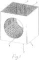
- Fig. 1 a first embodiment of a honeycomb body according to the invention in a perspective view
- Fig. 2 a second embodiment of a honeycomb body according to the invention.
- the honeycomb body 1 are traversed by mutually parallel, rectilinear channels 4 of rectangular cross-section, which extend between the end faces and are separated from each other by thin-walled webs.
- the channels 4 could also be square cross-section to have.
- the honeycomb bodies 1 can, for example, have a prism length of about 0.1-1.0 m, in particular about 0.15-0.3 m, and a prism face length of about 0.1-0.5 m, preferably from 0.1 to 0.30 m.
- honeycomb body 1 are expediently by extrusion (before firing), for example as 43 x 43 cell honeycomb body 1 with a geometry of 150 x 150 x 150 mm 3 and with flow channels 4 of 2.9 x 2, 9 mm or a cell wall thickness of 0.5 mm produced.
- the drilling of the recess 5 according to Fig. 1 takes place via a one-sided drilling process through the entire cross section of the honeycomb body 1.
- Fig. 2 made two drilling operations, for example, each to the center of the honeycomb body 1.
- the honeycomb body 1 twice (in the fürbohrtine each offset by 90 °) or four times (each offset by 90 ° / processed during the drilling process to the middle of the honeycomb body).
- honeycomb body 1 are strung together in practical use and stacked on top of each other.
- two honeycomb bodies 1 stacked one above the other can each be arranged rotated by 90 ° relative to one another in the stack.
- the two intersecting tubular recesses 5 ' resulting in each layer a network-like open Pipe system with extremely favorable transverse flow.
- only the lowermost or the two lowest honeycomb body ply (s) with tubular recesses 5, 5 ' may be provided in the honeycomb bodies 1 and the overlying layers of standard honeycomb bodies 1 without tubular recesses 5, 5 ' consist.
Landscapes
- Engineering & Computer Science (AREA)
- Chemical & Material Sciences (AREA)
- Mechanical Engineering (AREA)
- General Engineering & Computer Science (AREA)
- Physics & Mathematics (AREA)
- Thermal Sciences (AREA)
- Chemical Kinetics & Catalysis (AREA)
- Dispersion Chemistry (AREA)
- Organic Chemistry (AREA)
- Combustion & Propulsion (AREA)
- Ceramic Engineering (AREA)
- Materials Engineering (AREA)
- Geometry (AREA)
- Physical Or Chemical Processes And Apparatus (AREA)
- Catalysts (AREA)
- Filtering Of Dispersed Particles In Gases (AREA)
- Devices For Post-Treatments, Processing, Supply, Discharge, And Other Processes (AREA)
- Filtering Materials (AREA)
Description
- Die Erfindung betrifft einen Wabenkörper aus Keramikmaterial zur Verwendung in Anlagen für die Reinigung und/oder Regenerierung von Gasen, mit einem prismatischen Körper, der von einer Vielzahl zueinander paralleler, geradliniger Gasströmungskanälen durchzogen ist, die in beiden Stirnseiten des Wabenkörpers ausmünden, wobei der Wabenkörper zumindest eine Ausnehmung aufweist, die quer zur Richtung der Strömungskanäle orientiert ist.
- Die Anwendung von keramischen Wabenkörperstrukturen in thermischen Regeneratoren von Abluftreinigungsanlagen und für die Prozessluftregeneration ist weit verbreitet. So sind verschiedene keramische Wabenkörper bekannt, beispielsweise aus der
EP 0 472 605 B1 , die als Wärmespeichermassen in Regeneratoren in Anlagen zur Abgasbehandlung eingesetzt werden. Diese Wabenkörper werden üblicherweise in Stapeln angeordnet, wobei mindestens zwei in Richtung des jeweiligen Gasstromes, gegebenenfalls im Abstand voneinander angeordnete Wabenkörper mit ihren Kanälen fluchten. - Bei den bekannten Wärmespeichermassen handelt es sich um keramische Wabenkörper, die im Wesentlichen prismenförmig ausgebildet sind, parallel zur Prismenhauptachse Kanäle mit untereinander im Wesentlichen gleichen Kanalquerschnitten aufweisen, eine spezifische Oberfläche zwischen 200 und 3000 m2/m3 haben sowie einen hydraulischen Durchmesser zwischen 1 und 12 mm.
- Infolge der fluchtenden Anordnung der prismenförmigen Wabenkörper, insbesondere von deren Kanälen, setzt sich das Durchströmungsprofil des Querschnittes der Wärmespeicherkammer über alle Lagen des Stapels hinweg fort. Zonen, die in einer der Einströmungsseite des Gases zugewandten Lage schlecht oder gar nicht durchströmt sind, werden aufgrund der fluchtenden Anordnung der Kanäle im weiteren Verlauf gleichartig zur vorhergehenden Lage durchströmt. Gleiches gilt für stark durchströmte Zonen bzw. Kanäle. Der Fortsetzung des Strömungsprofils durch die Wabenkörperlagen liegt also im Wesentlichen die fluchtende Anordnung der Kanäle bzw. Prismen und eine nahezu durchgehend laminare Strömung zugrunde.
- Um eine möglichst hohe thermische Effizienz bei gleichzeitig niederem Druckverlust zu erzielen, werden Regeneratorbetten oft mit sehr großen Bettquerschnitten ausgelegt. Die angestrebten theoretisch hohen thermischen Rückgewinnungsgrade können jedoch nur bei einem möglichst hohen Ausnutzungsgrad der zur Verfügung gestellten Wärmespeichermasse erzielt werden. Ein hoher Ausnutzungsgrad ist u.a. gleichzusetzen mit einer möglichst gleichmäßigen Anströmung bzw. einer homogenen Strömungsverteilung über den Bettquerschnitt. Große Bettquerschnitte, ungünstige Ventil- bzw. Klappenpositionen und zu niedrige Druckverluste über das Regeneratorbett erschweren dieses Vorhaben. Häufig sind Bettquerschnitte vorgegeben, da es sich um bestehende Anlagen mit Wärmespeichermaterialien niedriger Effizienz und hohem Druckverlust (z.B. Schüttgut-Füllkörper) handelt. Deshalb wird ein Ersatz mit höher effizienten Wabenkörpern mit niedrigem Druckverlust angestrebt. Die theoretischen thermischen Rückgewinnungswerte werden in der Praxis dann oft nicht erreicht, weil aufgrund des niedrigen Druckverlustes und/oder der ungünstigen Anströmverhältnisse keine homogene Durchströmung des Regeneratorbettes erreicht werden kann und sich Zonen mit hoher Durchströmung und solche mit geringerer bzw. keiner Durchströmung im Regeneratorbett ausbilden. Die Zonen mit geringer Durchströmung tragen kaum zur Wärmerückgewinnung bei, und der theoretische Gesamtwirkungsgrad wird entsprechend der schlechten Strömungsverteilung nicht erreicht.
- Durch die in keramischen Wabenkörpern vorliegende, nicht kommunizierende Kanalstruktur können sich Luftströme innerhalb eines Wabenkörpers nicht vermischen bzw. verteilen. Auch die Stapelung der keramischen Wabenkörper mit ebenen Standflächen erlaubt keine Querverströmung zwischen den Lagen.
- Durch den Einsatz von Wabenkörpern mit strukturierten Endflächengeometrien (z.B. gemäß der
AT 412 817 B - Die
JP 2007 198706 A EP 0 315 047 A2 zeigen jeweils Wabenkörper für einen Wärmetauscher oder für einen Katalysator, bei welchem ein Fluid durch eine Vielzahl von parallel verlaufender Kanäle leitbar ist. Manche Kanäle sind durch eine gemeinsame Querbohrung miteinander verbunden, so daß eine Querströmung stattfinden kann. - Mit der
WO 97/27385 A1 - Die
US 3 887 741 A und dieUS 6 227 699 B1 lehren jeweils einen zylinderförmigen Wabenkörper, der an seinem Umfang verschiedene Einschnitte aufweist, um eine Querströmung des den Wabenkörper durchfließenden Fluids zu ermöglichen. - Das Ziel der Erfindung besteht darin, eine Wabenkörperstruktur zu entwickeln, die es ermöglicht, dass sich der Luftstrom trotz schlechter Verteilung vor dem Eintritt in das Regeneratorbett bereits kurz nach dem Eintritt möglichst über den gesamten Bettquerschnitt verteilt. Unter Eintrittsbereich eines Regeneratorbettes soll sowohl die Kaltzone eintrittseitig als auch die Heißzone austrittsseitig bei einer Mehrkammerkonstruktion verstanden werden.
- Derzeit werden in Regeneratorbetten mit ungünstigen Anströmungsverhältnissen folgende Maßnahmen gesetzt, um eine möglichst frühe (mit Bezug auf den zurückgelegten Weg der Strömung innerhalb des Bettes) Querverströmung zu erzielen:
- A) Lagen mit keramischen Sattelkörpern (Schüttgut)
- B) Lagen mit diagonalen Kanalstrukturen (Sulzerplatten)
- C) Perforierte Bleche unterhalb des Regeneratorbettes
- Ad A) Der Einsatz von keramischen Sattelkörpern in der untersten bzw. obersten Lage eines Regeneratorbettes hat aufgrund des hohen Druckverlustes (turbulente Strömung durch die Sattelkörper) und deren offenen Struktur zur Folge, dass sich der Luftstrom innerhalb dieser Lage horizontal gut verteilt. Nachteile dieser Sattelkörperlagen ist die hohe Verstopfungsgefahr, der niedere thermische Rückgewinnungsgrad der Sattelkörper und das teilweise Verlegen der anschließenden liegenden Wabenkörperkanäle. Des Weiteren kann sich die Schüttungsdichte der Sattelkörper während des Betriebes der Anlage durch thermische und mechanische Einflüsse verändern und die Position der darüber gestapelten Wabenkörperelemente nachteilig verändern.
- Ad B) Wabenkörper mit diagonalen Kanälen (Sulzerplatten) werden unter der Produktbezeichnung "Flex Ceramics" angeboten und haben im Vergleich zu Wabenkörpern mit Längskanälen eine wesentlich geringere Wärmeaustauschfläche und deshalb geringere thermische Effizienz. Die angestrebte Querverströmung wird nur durch eine relativ hohe Bauhöhe dieser Lage erzielt und geht auf Kosten der Gesamteffizienz der Anlage.
- Ad C) Perforierte Bleche unterhalb des Regeneratorbettes können bei Neuanlagen entsprechend eingeplant werden, sind jedoch in bestehenden Anlagen nur mit sehr hohem Aufwand nachzurüsten. Nachteil dieser Lochbleche ist, dass sie nur im Kaltbereich der Anlage eingesetzt werden können und korrosionsstabile Materialien relativ teuer sind.
- Die Aufgabe der Erfindung besteht darin, die geschilderten Mängel der Wabenkörperstrukturen nach dem Stand der Technik zu vermeiden und eine möglichst gute Querverströmung innerhalb eines keramischen Wabenkörpers bzw. einer Lage von Wabenkörpern zu erreichen. Diese Aufgabe wird erfindungsgemäß dadurch gelöst, dass die Ausnehmung einen rohrförmigen Querschnitt aufweist, welcher derart bemessen ist, dass die Anzahl der Strömungskanäle aus der Ebene des prismatischen Körpers, die quer zu der Seite liegt, an welcher die Ausnehmung mündet, und welche durch die Ausnehmung miteinander verbunden sind, größer ist als die Anzahl der Strömungskanäle dieser Ebene, die durch die Ausnehmung nicht miteinander verbunden sind. Dadurch werden innerhalb des Wabenkörpers Zonen geschaffen werden, in denen sich der Luftstrom quer zur vorgegebenen Strömungsrichtung des Luftstromes verteilen kann.
- Bei der Stapelung der Wabenkörper entsteht so eine netzwerkartige offene Röhrenstruktur, die eine signifikante Querverströmung innerhalb einer Wabenkörperlage ermöglicht.
- Vorzugsweise sind zwei einander kreuzende rohrförmige Ausnehmungen vorgesehen, die sich jeweils zwischen zwei einander gegenüberliegenden Seitenflächen des prismatischen Wabenkörpers erstrecken.
- Nach einem anderen Merkmal der Erfindung werden die rohrförmigen Ausnehmungen durch ein spanabhebendes Verfahren in dem ungebrannten Wabenkörper ausgebildet.
- Erfindungsgemäß können außerdem Einbauten in den rohrförmigen Ausnehmungen, welche einerseits die Querverströmung bzw. Verwirbelung des Luftstromes weiter fördern, vorgesehen werden, z.B. statische Mischerstrukturen.
- Wesentliche Vorteile der Erfindung gegenüber den bekannten Wärmespeicherkörpern sind
- eine kompakte Bauweise und mechanische Stabilität,
- die Möglichkeit, diese Technologie auf alle Zellgeometrien und entsprechenden Anwendungen anzuwenden,
- einen hohen Grad an Querverströmung im Verhältnis zu zurückgelegter Strecke in Strömungsrichtung zu erreichen,
- einen hohen Wärmerückgewinnungsgrad der verbleibenden Wabenstruktur sicherzustellen,
- die Verstopfungsgefahr gegenüber den Standardwabenstrukturen nicht zu erhöhen, und
- eine Anwendung auch in den Heißzonen des Regeneratorbettes zu ermöglichen.
- Die Erfindung wird nachfolgend an Ausführungsbeispielen unter Bezugnahme auf die Zeichnungen näher erläutert. Es zeigen:
Fig. 1 eine erste Ausführungsform eines Wabenkörpers gemäß der Erfindung in einer Perspektivansicht, undFig. 2 eine zweite Ausführungsform eines erfindungsgemäßen Wabenkörpers. - Die in den
Fig. 1 und2 dargestellten keramischen Wabenkörper 1 haben die Gestalt eines rechteckigen Prismas mit zueinander parallelen Stirnflächen 2, 3. Die Wabenkörper 1 sind von zueinander parallelen, geradlinigen Kanälen 4 mit rechteckigem Querschnitt durchzogen, die sich zwischen den Stirnflächen erstrecken und durch dünnwandige Stege voneinander getrennt sind. Die Kanäle 4 könnten auch quadratischen Querschnitt haben. Für den praktischen Einsatz können die Wabenkörper 1 beispielsweise eine Prismenlänge von etwa 0,1 - 1,0 m, insbesondere von etwa 0,15 - 0,3 m und eine Prismenstirnflächen-Seitenlänge von etwa 0,1 - 0,5 m, vorzugsweise von 0,1 - 0,30 m aufweisen. - Die in den
Fig. 1 und2 gezeigten Wabenkörper 1 werden zweckmäßig durch Strangpressen (vor dem Brennen) beispielsweise als 43 x 43 Zellen-Wabenkörper 1 mit einer Geometrie von 150 x 150 x 150 mm3 und mit Strömungskanälen 4 von 2,9 x 2, 9 mm bzw. einer Zellwandstärke von 0,5 mm hergestellt. - Wie die
Fig. 1 und2 außerdem zeigen, sind die Wabenkörper 1 mit rohrförmigen Ausnehmungen 5, 5' versehen. Die Ausnehmungen 5, 5' werden nach dem Strangpressen durch spanabhebende Verfahren an den "grünen" (ungebrannten) Wabenkörpern 1 erhalten, vorzugsweise durch Bohren mittels einem Kernbohrer entsprechenden Durchmessers. - Das Bohren der Ausnehmung 5 gemäß
Fig. 1 erfolgt über einen einseitigen Bohrvorgang durch den gesamten Querschnitt des Wabenkörpers 1. Alternativ werden gemäßFig. 2 zwei Bohrvorgänge vorgenommen, z.B. jeweils bis zur Mitte des Wabenkörpers 1. Zur Erzielung der kreuzweise angeordneten rohrförmigen Ausnehmungen 5' gemäßFig. 2 , die sich jeweils zwischen zwei einander gegenüberliegenden Seitenflächen 1' erstrecken, wird der Wabenkörper 1 zweimal (bei der Durchbohrvariante jeweils um 90° versetzt) bzw. viermal (jeweils um 90° versetzt/beim Bohrvorgang bis zur Mitte des Wabenkörpers) bearbeitet. - Die erfindungsgemäßen Wabenkörper 1 werden im praktischen Einsatz aneinandergereiht und übereinander gestapelt. Dabei können beispielsweise zwei übereinander gestapelte Wabenkörper 1 jeweils um 90° zueinander verdreht im Stapel angeordnet werden. Bei Aneinanderreihung bzw. Stapelung von Wabenkörpern 1, die zwei einander kreuzende rohrförmige Ausnehmungen 5' aufweisen, ergibt sich in jeder Lage ein netzwerkartiges offenes Rohrsystem mit außerordentlich günstiger Querverströmung. Es kann bzw. können in einem Stapel aber auch nur die unterste oder die beiden untersten Wabenkörperlage(n) mit rohrförmigen Ausnehmungen 5, 5' in den Wabenkörpern 1 versehen sein und die darüber liegenden Lagen aus Standard-Wabenkörpern 1 ohne rohrförmige Ausnehmungen 5, 5' bestehen.
Claims (4)
- Wabenkörper aus Keramikmaterial zur Verwendung in Anlagen für die Reinigung und/oder Regenerierung von Gasen, mit einem prismatischen Körper, der von einer Vielzahl zueinander paralleler, geradliniger Gasströmungskanälen durchzogen ist, die in beiden Stirnseiten des Wabenkörpers ausmünden, wobei der Wabenkörper (1) zumindest eine Ausnehmung (5, 5') aufweist, die quer zur Richtung der Strömungskanäle (4) orientiert ist, dadurch gekennzeichnet, dass die Ausnehmung (5, 5') einen rohrförmigen Querschnitt aufweist, welcher derart bemessen ist, dass die Anzahl der Strömungskanäle (4) aus der Ebene des prismatischen Körpers, die quer zu der Seite liegt, an welcher die Ausnehmung (5, 5') mündet, und welche durch die Ausnehmung (5, 5') miteinander verbunden sind, größer ist als die Anzahl der Strömungskanäle (4) dieser Ebene, die durch die Ausnehmung (5, 5') nicht miteinander verbunden sind.
- Wabenkörper nach Anspruch 1, dadurch gekennzeichnet, dass zwei einander kreuzende rohrförmige Ausnehmungen (5') vorgesehen sind, die sich jeweils zwischen zwei einander gegenüberliegenden Seitenflächen (1') des prismatischen Wabenkörpers (1) erstrecken.
- Wabenkörper nach Anspruch 1 oder 2, dadurch gekennzeichnet, dass die rohrförmigen Ausnehmungen (5, 5') durch ein spanabhebendes Verfahren in dem ungebrannten Wabenkörper (1) ausgebildet werden.
- Wabenkörper nach einem der Ansprüche 1 bis 3, dadurch gekennzeichnet, dass in den rohrförmigen Ausnehmungen (5, 5') Einbauten vorgesehen sind, welche die Querströmung bzw. Verwirbelung des Luftstromes fördern, insbesondere statische Mischerstrukturen.
Applications Claiming Priority (2)
| Application Number | Priority Date | Filing Date | Title |
|---|---|---|---|
| ATA1193/2012A AT513563B1 (de) | 2012-11-08 | 2012-11-08 | Wabenkörper aus Keramikmaterial |
| PCT/AT2013/000160 WO2014071424A1 (de) | 2012-11-08 | 2013-10-03 | Wabenkörper aus keramikmaterial |
Publications (2)
| Publication Number | Publication Date |
|---|---|
| EP2917672A1 EP2917672A1 (de) | 2015-09-16 |
| EP2917672B1 true EP2917672B1 (de) | 2017-12-06 |
Family
ID=49486311
Family Applications (1)
| Application Number | Title | Priority Date | Filing Date |
|---|---|---|---|
| EP13782931.3A Active EP2917672B1 (de) | 2012-11-08 | 2013-10-03 | Wabenkörper aus keramikmaterial |
Country Status (4)
| Country | Link |
|---|---|
| US (1) | US9630135B2 (de) |
| EP (1) | EP2917672B1 (de) |
| AT (1) | AT513563B1 (de) |
| WO (1) | WO2014071424A1 (de) |
Families Citing this family (1)
| Publication number | Priority date | Publication date | Assignee | Title |
|---|---|---|---|---|
| CN110895115A (zh) * | 2019-12-09 | 2020-03-20 | 江西博鑫精陶环保科技有限公司 | 一种具有气流均匀分布的异形蜂窝陶瓷蓄热体 |
Family Cites Families (23)
| Publication number | Priority date | Publication date | Assignee | Title |
|---|---|---|---|---|
| AT6726B (de) | 1900-09-10 | 1902-02-10 | Vereinigte Maschinenfabrik Augsburg & Maschinenbauges Nuernberg Ag | |
| US3887741A (en) * | 1973-08-13 | 1975-06-03 | Corning Glass Works | Thin-walled honeycombed substrate with axial discontinuities in the periphery |
| JPS60141541A (ja) * | 1983-12-29 | 1985-07-26 | Nippon Soken Inc | ブロツク型熱交換エレメントの製造方法 |
| DE3737248A1 (de) | 1987-11-03 | 1989-05-18 | Basf Ag | Monolithischer katalysatorkoerper |
| ATA116889A (de) | 1989-05-17 | 1997-11-15 | Kanzler Walter | Verfahren zur thermischen abgasverbrennung |
| US5108685A (en) * | 1990-12-17 | 1992-04-28 | Corning Incorporated | Method and apparatus for forming an article with multi-cellular densities and/or geometries |
| DE4324347A1 (de) * | 1992-07-23 | 1994-01-27 | Noritake Co Ltd | Monolithischer Keramikfilter |
| US5373634A (en) * | 1993-09-14 | 1994-12-20 | Corning Incorporate | Method of forming alternating-flow heat exchangers |
| WO1997027385A1 (fr) | 1996-01-22 | 1997-07-31 | Institut Français Du Petrole | Precipitateur pour combustion a l'echappement de moteurs diesel ou essence, et procede associe |
| US6077436A (en) * | 1997-01-06 | 2000-06-20 | Corning Incorporated | Device for altering a feed stock and method for using same |
| US6227699B1 (en) | 1999-12-20 | 2001-05-08 | Corning Incorporated | Spiral cut honeycomb body for fluid mixing |
| JP2002177793A (ja) * | 2000-10-02 | 2002-06-25 | Nippon Soken Inc | セラミック担体およびセラミック触媒体 |
| DE10229405B4 (de) | 2002-06-29 | 2006-01-26 | Eisenmann Maschinenbau Gmbh & Co. Kg | Keramischer Wabenkörper zur Verwendung in einer thermischen Abgasbehandlungsvorrichtung |
| AT6726U1 (de) * | 2002-12-19 | 2004-03-25 | Roitner Johann Dipl Ing | Formkörper sowie verwendung eines formkörpers |
| NO321668B1 (no) * | 2003-04-11 | 2006-06-19 | Norsk Hydro As | Enhet for a fordele to fluider inn og ut av kanalene i en monolittisk struktur samt fremgangsmate og utstyr for a overfore masse og/eller varme mellom to fluider |
| DE102005007403A1 (de) * | 2005-02-18 | 2006-08-31 | Emitec Gesellschaft Für Emissionstechnologie Mbh | Wabenkörper mit internen Kavernen |
| AT502666B8 (de) * | 2005-12-16 | 2007-07-15 | Porzellanfabrik Frauenthal Gmb | Verfahren und wabenkörper zum reinigen und/oder regenerieren von gasen |
| JP2007198706A (ja) * | 2006-01-30 | 2007-08-09 | National Institute Of Advanced Industrial & Technology | 交差した流路方向を有する内部発熱式の熱交換構造体 |
| JP4521513B2 (ja) * | 2006-01-30 | 2010-08-11 | 独立行政法人産業技術総合研究所 | 内部発熱式の熱交換構造体 |
| CN201152709Y (zh) | 2007-08-13 | 2008-11-19 | 宁德市威克陶瓷有限公司 | 大规格组合式蜂窝陶瓷蓄热体 |
| US8211524B1 (en) * | 2008-04-24 | 2012-07-03 | Siemens Energy, Inc. | CMC anchor for attaching a ceramic thermal barrier to metal |
| JP2010271031A (ja) * | 2009-04-23 | 2010-12-02 | Ngk Insulators Ltd | セラミックス熱交換器、及びその製造方法 |
| TW201109078A (en) * | 2009-04-30 | 2011-03-16 | Corning Inc | Minireactor array |
-
2012
- 2012-11-08 AT ATA1193/2012A patent/AT513563B1/de active
-
2013
- 2013-10-03 US US14/440,032 patent/US9630135B2/en active Active
- 2013-10-03 WO PCT/AT2013/000160 patent/WO2014071424A1/de not_active Ceased
- 2013-10-03 EP EP13782931.3A patent/EP2917672B1/de active Active
Also Published As
| Publication number | Publication date |
|---|---|
| AT513563A1 (de) | 2014-05-15 |
| US9630135B2 (en) | 2017-04-25 |
| WO2014071424A1 (de) | 2014-05-15 |
| EP2917672A1 (de) | 2015-09-16 |
| US20150290574A1 (en) | 2015-10-15 |
| AT513563B1 (de) | 2014-09-15 |
Similar Documents
| Publication | Publication Date | Title |
|---|---|---|
| EP0758917B1 (de) | Statischer mikro-vermischer | |
| EP1038575B1 (de) | Plattenreaktor | |
| DE2838093C2 (de) | ||
| EP1996889A1 (de) | Plattenwärmetauscher, verfahren zu dessen herstellung und dessen verwendung | |
| WO2018154063A1 (de) | Wärmeübertrager und reaktor | |
| EP0776695A1 (de) | Packung für eine Gegenstrom-Hochdruckkolonne | |
| EP0980703A1 (de) | Statischer Mischer | |
| WO2008034664A1 (de) | Filterelement, insbesondere zur filterung von abgasen einer brennkraftmaschine | |
| DE2705123C2 (de) | Wärmetauscher und Verfahren zur Herstellung eines Wärmetauschers | |
| DE10249724A1 (de) | Hochleistungs-Temperierkanäle | |
| EP2647942A1 (de) | Mikrofluidik-Bauteil und Verfahren zu seiner Herstellung | |
| DE102020131370A1 (de) | Plattenwärmetauscher mit die Strömung leitenden Leitblechen | |
| AT513563B1 (de) | Wabenkörper aus Keramikmaterial | |
| DE102005005509B4 (de) | Blockwärmetauscher aus Graphit | |
| EP3822569A1 (de) | Wärmetauscher | |
| DE602006000699T2 (de) | Filtereinrichtung für Diesel-Abgase | |
| DE102017004671A1 (de) | Vorrichtung zum Kühlen, Wärmen oder Wärmeübertragen | |
| EP2431700B1 (de) | Kreuzstrom-Mikrowärmeübertrager | |
| EP0996848B1 (de) | Wärmetauscher | |
| DE2753189A1 (de) | Oberflaechenausbildung in einer vorrichtung zum fuehren von fluiden | |
| AT412531B (de) | Wabenkörpereinrichtung für die thermische abgasbehandlung | |
| DE10234771B4 (de) | Wärmespeicherbett für regenerative Wärmeübertragung | |
| WO2004113816A1 (de) | Wabenkörpereinrichtung für die thermische abgasbehandlung | |
| DE102018216841B4 (de) | Partikelfilter | |
| EP2026894A1 (de) | Filtereinrichtung, insbesondere für ein abgassystem einer brennkraftmaschine |
Legal Events
| Date | Code | Title | Description |
|---|---|---|---|
| PUAI | Public reference made under article 153(3) epc to a published international application that has entered the european phase |
Free format text: ORIGINAL CODE: 0009012 |
|
| 17P | Request for examination filed |
Effective date: 20150409 |
|
| AK | Designated contracting states |
Kind code of ref document: A1 Designated state(s): AL AT BE BG CH CY CZ DE DK EE ES FI FR GB GR HR HU IE IS IT LI LT LU LV MC MK MT NL NO PL PT RO RS SE SI SK SM TR |
|
| AX | Request for extension of the european patent |
Extension state: BA ME |
|
| DAX | Request for extension of the european patent (deleted) | ||
| GRAP | Despatch of communication of intention to grant a patent |
Free format text: ORIGINAL CODE: EPIDOSNIGR1 |
|
| RIC1 | Information provided on ipc code assigned before grant |
Ipc: F28D 17/02 20060101AFI20170627BHEP Ipc: F28F 21/04 20060101ALI20170627BHEP |
|
| INTG | Intention to grant announced |
Effective date: 20170718 |
|
| GRAS | Grant fee paid |
Free format text: ORIGINAL CODE: EPIDOSNIGR3 |
|
| GRAA | (expected) grant |
Free format text: ORIGINAL CODE: 0009210 |
|
| AK | Designated contracting states |
Kind code of ref document: B1 Designated state(s): AL AT BE BG CH CY CZ DE DK EE ES FI FR GB GR HR HU IE IS IT LI LT LU LV MC MK MT NL NO PL PT RO RS SE SI SK SM TR |
|
| REG | Reference to a national code |
Ref country code: GB Ref legal event code: FG4D Free format text: NOT ENGLISH |
|
| REG | Reference to a national code |
Ref country code: AT Ref legal event code: REF Ref document number: 952766 Country of ref document: AT Kind code of ref document: T Effective date: 20171215 Ref country code: CH Ref legal event code: EP |
|
| REG | Reference to a national code |
Ref country code: IE Ref legal event code: FG4D Free format text: LANGUAGE OF EP DOCUMENT: GERMAN |
|
| REG | Reference to a national code |
Ref country code: DE Ref legal event code: R096 Ref document number: 502013008981 Country of ref document: DE |
|
| REG | Reference to a national code |
Ref country code: NL Ref legal event code: MP Effective date: 20171206 |
|
| REG | Reference to a national code |
Ref country code: LT Ref legal event code: MG4D |
|
| PG25 | Lapsed in a contracting state [announced via postgrant information from national office to epo] |
Ref country code: ES Free format text: LAPSE BECAUSE OF FAILURE TO SUBMIT A TRANSLATION OF THE DESCRIPTION OR TO PAY THE FEE WITHIN THE PRESCRIBED TIME-LIMIT Effective date: 20171206 Ref country code: NO Free format text: LAPSE BECAUSE OF FAILURE TO SUBMIT A TRANSLATION OF THE DESCRIPTION OR TO PAY THE FEE WITHIN THE PRESCRIBED TIME-LIMIT Effective date: 20180306 Ref country code: SE Free format text: LAPSE BECAUSE OF FAILURE TO SUBMIT A TRANSLATION OF THE DESCRIPTION OR TO PAY THE FEE WITHIN THE PRESCRIBED TIME-LIMIT Effective date: 20171206 Ref country code: FI Free format text: LAPSE BECAUSE OF FAILURE TO SUBMIT A TRANSLATION OF THE DESCRIPTION OR TO PAY THE FEE WITHIN THE PRESCRIBED TIME-LIMIT Effective date: 20171206 Ref country code: LT Free format text: LAPSE BECAUSE OF FAILURE TO SUBMIT A TRANSLATION OF THE DESCRIPTION OR TO PAY THE FEE WITHIN THE PRESCRIBED TIME-LIMIT Effective date: 20171206 |
|
| PG25 | Lapsed in a contracting state [announced via postgrant information from national office to epo] |
Ref country code: LV Free format text: LAPSE BECAUSE OF FAILURE TO SUBMIT A TRANSLATION OF THE DESCRIPTION OR TO PAY THE FEE WITHIN THE PRESCRIBED TIME-LIMIT Effective date: 20171206 Ref country code: BG Free format text: LAPSE BECAUSE OF FAILURE TO SUBMIT A TRANSLATION OF THE DESCRIPTION OR TO PAY THE FEE WITHIN THE PRESCRIBED TIME-LIMIT Effective date: 20180306 Ref country code: HR Free format text: LAPSE BECAUSE OF FAILURE TO SUBMIT A TRANSLATION OF THE DESCRIPTION OR TO PAY THE FEE WITHIN THE PRESCRIBED TIME-LIMIT Effective date: 20171206 Ref country code: RS Free format text: LAPSE BECAUSE OF FAILURE TO SUBMIT A TRANSLATION OF THE DESCRIPTION OR TO PAY THE FEE WITHIN THE PRESCRIBED TIME-LIMIT Effective date: 20171206 Ref country code: GR Free format text: LAPSE BECAUSE OF FAILURE TO SUBMIT A TRANSLATION OF THE DESCRIPTION OR TO PAY THE FEE WITHIN THE PRESCRIBED TIME-LIMIT Effective date: 20180307 |
|
| PG25 | Lapsed in a contracting state [announced via postgrant information from national office to epo] |
Ref country code: NL Free format text: LAPSE BECAUSE OF FAILURE TO SUBMIT A TRANSLATION OF THE DESCRIPTION OR TO PAY THE FEE WITHIN THE PRESCRIBED TIME-LIMIT Effective date: 20171206 |
|
| PG25 | Lapsed in a contracting state [announced via postgrant information from national office to epo] |
Ref country code: SK Free format text: LAPSE BECAUSE OF FAILURE TO SUBMIT A TRANSLATION OF THE DESCRIPTION OR TO PAY THE FEE WITHIN THE PRESCRIBED TIME-LIMIT Effective date: 20171206 Ref country code: EE Free format text: LAPSE BECAUSE OF FAILURE TO SUBMIT A TRANSLATION OF THE DESCRIPTION OR TO PAY THE FEE WITHIN THE PRESCRIBED TIME-LIMIT Effective date: 20171206 Ref country code: CZ Free format text: LAPSE BECAUSE OF FAILURE TO SUBMIT A TRANSLATION OF THE DESCRIPTION OR TO PAY THE FEE WITHIN THE PRESCRIBED TIME-LIMIT Effective date: 20171206 |
|
| PG25 | Lapsed in a contracting state [announced via postgrant information from national office to epo] |
Ref country code: SM Free format text: LAPSE BECAUSE OF FAILURE TO SUBMIT A TRANSLATION OF THE DESCRIPTION OR TO PAY THE FEE WITHIN THE PRESCRIBED TIME-LIMIT Effective date: 20171206 Ref country code: IT Free format text: LAPSE BECAUSE OF FAILURE TO SUBMIT A TRANSLATION OF THE DESCRIPTION OR TO PAY THE FEE WITHIN THE PRESCRIBED TIME-LIMIT Effective date: 20171206 Ref country code: PL Free format text: LAPSE BECAUSE OF FAILURE TO SUBMIT A TRANSLATION OF THE DESCRIPTION OR TO PAY THE FEE WITHIN THE PRESCRIBED TIME-LIMIT Effective date: 20171206 Ref country code: RO Free format text: LAPSE BECAUSE OF FAILURE TO SUBMIT A TRANSLATION OF THE DESCRIPTION OR TO PAY THE FEE WITHIN THE PRESCRIBED TIME-LIMIT Effective date: 20171206 |
|
| REG | Reference to a national code |
Ref country code: DE Ref legal event code: R097 Ref document number: 502013008981 Country of ref document: DE |
|
| PG25 | Lapsed in a contracting state [announced via postgrant information from national office to epo] |
Ref country code: MT Free format text: LAPSE BECAUSE OF FAILURE TO SUBMIT A TRANSLATION OF THE DESCRIPTION OR TO PAY THE FEE WITHIN THE PRESCRIBED TIME-LIMIT Effective date: 20171206 |
|
| PLBE | No opposition filed within time limit |
Free format text: ORIGINAL CODE: 0009261 |
|
| STAA | Information on the status of an ep patent application or granted ep patent |
Free format text: STATUS: NO OPPOSITION FILED WITHIN TIME LIMIT |
|
| 26N | No opposition filed |
Effective date: 20180907 |
|
| PG25 | Lapsed in a contracting state [announced via postgrant information from national office to epo] |
Ref country code: SI Free format text: LAPSE BECAUSE OF FAILURE TO SUBMIT A TRANSLATION OF THE DESCRIPTION OR TO PAY THE FEE WITHIN THE PRESCRIBED TIME-LIMIT Effective date: 20171206 Ref country code: DK Free format text: LAPSE BECAUSE OF FAILURE TO SUBMIT A TRANSLATION OF THE DESCRIPTION OR TO PAY THE FEE WITHIN THE PRESCRIBED TIME-LIMIT Effective date: 20171206 |
|
| REG | Reference to a national code |
Ref country code: CH Ref legal event code: PL |
|
| GBPC | Gb: european patent ceased through non-payment of renewal fee |
Effective date: 20181003 |
|
| REG | Reference to a national code |
Ref country code: BE Ref legal event code: MM Effective date: 20181031 |
|
| PG25 | Lapsed in a contracting state [announced via postgrant information from national office to epo] |
Ref country code: LU Free format text: LAPSE BECAUSE OF NON-PAYMENT OF DUE FEES Effective date: 20181003 Ref country code: MC Free format text: LAPSE BECAUSE OF FAILURE TO SUBMIT A TRANSLATION OF THE DESCRIPTION OR TO PAY THE FEE WITHIN THE PRESCRIBED TIME-LIMIT Effective date: 20171206 |
|
| REG | Reference to a national code |
Ref country code: IE Ref legal event code: MM4A |
|
| PG25 | Lapsed in a contracting state [announced via postgrant information from national office to epo] |
Ref country code: BE Free format text: LAPSE BECAUSE OF NON-PAYMENT OF DUE FEES Effective date: 20181031 Ref country code: CH Free format text: LAPSE BECAUSE OF NON-PAYMENT OF DUE FEES Effective date: 20181031 Ref country code: LI Free format text: LAPSE BECAUSE OF NON-PAYMENT OF DUE FEES Effective date: 20181031 Ref country code: FR Free format text: LAPSE BECAUSE OF NON-PAYMENT OF DUE FEES Effective date: 20181031 |
|
| PG25 | Lapsed in a contracting state [announced via postgrant information from national office to epo] |
Ref country code: IE Free format text: LAPSE BECAUSE OF NON-PAYMENT OF DUE FEES Effective date: 20181003 Ref country code: GB Free format text: LAPSE BECAUSE OF NON-PAYMENT OF DUE FEES Effective date: 20181003 |
|
| REG | Reference to a national code |
Ref country code: AT Ref legal event code: MM01 Ref document number: 952766 Country of ref document: AT Kind code of ref document: T Effective date: 20181003 |
|
| PG25 | Lapsed in a contracting state [announced via postgrant information from national office to epo] |
Ref country code: AT Free format text: LAPSE BECAUSE OF NON-PAYMENT OF DUE FEES Effective date: 20181003 |
|
| PG25 | Lapsed in a contracting state [announced via postgrant information from national office to epo] |
Ref country code: TR Free format text: LAPSE BECAUSE OF FAILURE TO SUBMIT A TRANSLATION OF THE DESCRIPTION OR TO PAY THE FEE WITHIN THE PRESCRIBED TIME-LIMIT Effective date: 20171206 |
|
| PG25 | Lapsed in a contracting state [announced via postgrant information from national office to epo] |
Ref country code: PT Free format text: LAPSE BECAUSE OF FAILURE TO SUBMIT A TRANSLATION OF THE DESCRIPTION OR TO PAY THE FEE WITHIN THE PRESCRIBED TIME-LIMIT Effective date: 20171206 |
|
| PG25 | Lapsed in a contracting state [announced via postgrant information from national office to epo] |
Ref country code: CY Free format text: LAPSE BECAUSE OF FAILURE TO SUBMIT A TRANSLATION OF THE DESCRIPTION OR TO PAY THE FEE WITHIN THE PRESCRIBED TIME-LIMIT Effective date: 20171206 Ref country code: HU Free format text: LAPSE BECAUSE OF FAILURE TO SUBMIT A TRANSLATION OF THE DESCRIPTION OR TO PAY THE FEE WITHIN THE PRESCRIBED TIME-LIMIT; INVALID AB INITIO Effective date: 20131003 Ref country code: MK Free format text: LAPSE BECAUSE OF NON-PAYMENT OF DUE FEES Effective date: 20171206 |
|
| PG25 | Lapsed in a contracting state [announced via postgrant information from national office to epo] |
Ref country code: AL Free format text: LAPSE BECAUSE OF FAILURE TO SUBMIT A TRANSLATION OF THE DESCRIPTION OR TO PAY THE FEE WITHIN THE PRESCRIBED TIME-LIMIT Effective date: 20171206 Ref country code: IS Free format text: LAPSE BECAUSE OF FAILURE TO SUBMIT A TRANSLATION OF THE DESCRIPTION OR TO PAY THE FEE WITHIN THE PRESCRIBED TIME-LIMIT Effective date: 20180406 |
|
| PGFP | Annual fee paid to national office [announced via postgrant information from national office to epo] |
Ref country code: DE Payment date: 20251231 Year of fee payment: 13 |