EP0996848B1 - Wärmetauscher - Google Patents
Wärmetauscher Download PDFInfo
- Publication number
- EP0996848B1 EP0996848B1 EP98921490A EP98921490A EP0996848B1 EP 0996848 B1 EP0996848 B1 EP 0996848B1 EP 98921490 A EP98921490 A EP 98921490A EP 98921490 A EP98921490 A EP 98921490A EP 0996848 B1 EP0996848 B1 EP 0996848B1
- Authority
- EP
- European Patent Office
- Prior art keywords
- heat exchanger
- exchanger according
- partial elements
- pipe
- fiber
- Prior art date
- Legal status (The legal status is an assumption and is not a legal conclusion. Google has not performed a legal analysis and makes no representation as to the accuracy of the status listed.)
- Expired - Lifetime
Links
Images



Classifications
-
- F—MECHANICAL ENGINEERING; LIGHTING; HEATING; WEAPONS; BLASTING
- F28—HEAT EXCHANGE IN GENERAL
- F28F—DETAILS OF HEAT-EXCHANGE AND HEAT-TRANSFER APPARATUS, OF GENERAL APPLICATION
- F28F1/00—Tubular elements; Assemblies of tubular elements
- F28F1/10—Tubular elements and assemblies thereof with means for increasing heat-transfer area, e.g. with fins, with projections, with recesses
- F28F1/12—Tubular elements and assemblies thereof with means for increasing heat-transfer area, e.g. with fins, with projections, with recesses the means being only outside the tubular element
- F28F1/24—Tubular elements and assemblies thereof with means for increasing heat-transfer area, e.g. with fins, with projections, with recesses the means being only outside the tubular element and extending transversely
- F28F1/32—Tubular elements and assemblies thereof with means for increasing heat-transfer area, e.g. with fins, with projections, with recesses the means being only outside the tubular element and extending transversely the means having portions engaging further tubular elements
-
- F—MECHANICAL ENGINEERING; LIGHTING; HEATING; WEAPONS; BLASTING
- F28—HEAT EXCHANGE IN GENERAL
- F28D—HEAT-EXCHANGE APPARATUS, NOT PROVIDED FOR IN ANOTHER SUBCLASS, IN WHICH THE HEAT-EXCHANGE MEDIA DO NOT COME INTO DIRECT CONTACT
- F28D7/00—Heat-exchange apparatus having stationary tubular conduit assemblies for both heat-exchange media, the media being in contact with different sides of a conduit wall
- F28D7/0008—Heat-exchange apparatus having stationary tubular conduit assemblies for both heat-exchange media, the media being in contact with different sides of a conduit wall the conduits for one medium being in heat conductive contact with the conduits for the other medium
-
- F—MECHANICAL ENGINEERING; LIGHTING; HEATING; WEAPONS; BLASTING
- F28—HEAT EXCHANGE IN GENERAL
- F28F—DETAILS OF HEAT-EXCHANGE AND HEAT-TRANSFER APPARATUS, OF GENERAL APPLICATION
- F28F21/00—Constructions of heat-exchange apparatus characterised by the selection of particular materials
- F28F21/04—Constructions of heat-exchange apparatus characterised by the selection of particular materials of ceramic; of concrete; of natural stone
-
- F—MECHANICAL ENGINEERING; LIGHTING; HEATING; WEAPONS; BLASTING
- F28—HEAT EXCHANGE IN GENERAL
- F28F—DETAILS OF HEAT-EXCHANGE AND HEAT-TRANSFER APPARATUS, OF GENERAL APPLICATION
- F28F9/00—Casings; Header boxes; Auxiliary supports for elements; Auxiliary members within casings
- F28F9/007—Auxiliary supports for elements
- F28F9/013—Auxiliary supports for elements for tubes or tube-assemblies
- F28F9/0131—Auxiliary supports for elements for tubes or tube-assemblies formed by plates
-
- F—MECHANICAL ENGINEERING; LIGHTING; HEATING; WEAPONS; BLASTING
- F28—HEAT EXCHANGE IN GENERAL
- F28F—DETAILS OF HEAT-EXCHANGE AND HEAT-TRANSFER APPARATUS, OF GENERAL APPLICATION
- F28F2275/00—Fastening; Joining
- F28F2275/02—Fastening; Joining by using bonding materials; by embedding elements in particular materials
Definitions
- the present invention relates to a heat exchanger, the at least a first Pipe for passing a first fluid to be cooled, which emits heat and at least one second tube for passing a heat absorbing second Fluid, wherein at least the first tube, made of a fluid-tight, corrosion-resistant and oxidation-resistant material, in one of several individual Supporting elements formed from sub-elements made of SiC-containing material in a bore the sub-elements is held.
- Such a heat exchanger is known from EP-A1 0 479 657.
- This heat exchanger is made up of a bundle of first tubes that are spaced apart by means of a Support structure are held, built.
- the supporting structure consists of individual Plates.
- a first fluid, which is cooled, is passed through the first tubes shall be.
- the entire support structure is from a second tube, i.e. a cladding tube, surrounded, which has an inlet and outlet, via which a second fluid to the the first pipes is passed to the heat given off by the first pipes dissipate.
- the first pipes and the supporting structure that fixes the first pipes consist of silicon carbide.
- the support plates are first produced as green bodies with appropriate Holes into which the first silicon carbide tubes are to be inserted. This is followed by sintering at temperatures between 1900 to 2500 ° C, around the Support plates with the first tubes firmly, i.e. immovable to connect. Thereby, that the individual first tubes are kept at a distance from one another, the second fluid flows well from all sides to remove the heat.
- Such an arrangement poses problems in particular in that if a single one of the first pipes is defective, the entire heat exchanger is unusable is because a separation of its individual components is practically impossible is.
- the present one is now Invention, the object of a heat exchanger from a corrosion and oxidation resistant material to create a high mechanical Strength that withstands high temperature cycling cycles, one high efficiency, i.e. good heat exchange between the two fluids enables, and in addition, simple, despite the materials to be used is buildable and with regard to defective parts an easy exchange of such parts enables.
- This task is solved, starting from a heat exchanger with the characteristics of the preamble of claim 1, characterized in that the support structure from stacked and connected to one another via a SiC-containing connecting layer plate or disc-shaped partial elements made of a carbon and / or ceramic fiber reinforced composite is built that at least an expansion compensation layer between the first tube and the supporting structure is made of ceramic material and / or carbon and that at least a second tube adjacent to the at least one first tube in one the sub-elements introduced hole is held.
- the heat exchanger according to the invention is characterized on the one hand in that it is made up of individual, plate-shaped or disc-shaped partial elements which Have cavities and are stacked on top of one another and contain a silicon carbide Connection layer are interconnected.
- the first pipes carrying the first fluid are then inserted into the support structure, such that an expansion compensation layer between the first tubes and the support structure is arranged from ceramic material and / or carbon.
- the support structure and the tubes are, at least those Pipes that carry the first fluid are mechanically decoupled. Only when a fluid is passed through the heat exchanger at high temperature Expansion of the first pipes, so that these, when the heat exchanger is in operation, are firmly anchored to the supporting structure. Due to the stretch compensation layer it is possible to operate the heat exchanger at working temperatures that are even higher than 1400 ° C; In addition, an internal pressure can be applied to the first pipes be provided. The high working temperature and the high internal pressure lead to a higher efficiency.
- fluid in the description and the claims, in the sense of the explanations, this includes not only liquid media, but also gaseous media or mixtures of liquid and gaseous media that pass through the tubes of the heat exchanger are passed through, which also contain solid particles can carry along.
- the supporting structure is made up of individual plates or panes, you can use prefabricated, standardized parts of any length heat exchanger structures such individual plates or disks are built up with the corresponding ones Cavities or holes into which the pipes that carry the fluids are inserted become. Due to the expansion compensation layer made of ceramic material and / or Carbon is obtained from the pipes that are in the operating state of the heat exchanger are firmly fixed in the supporting structure, are released when the heat exchanger is out of order so that there are no voltages at the transitions be saved and it is also possible to have individual, possibly defective pipes the heat exchanger, without special measures, and by others Replace pipes. Due to the inventive design of the support structure and of the pipes will only be low when the pipes are subjected to internal pressure Train claims what a safe and trouble-free operation of a heat exchanger is an essential advantage.
- the first pipes made of a fluid-tight, corrosion or oxidation resistant Material can be commercially available pipes, which are preferably made of monolithic Ceramic, are formed from silicon carbide, silicon nitride, cordierite or mullite.
- a monolithic ceramics will always be beneficial when gas tightness is primary is required, while the first tubes made of silicon carbide and silicon nitride are then used should be when under particularly high temperatures with low material expansion and high temperature changes. Cordierite or mullite should then be used for the first pipes if on the one hand work under high temperatures, on the other hand a good oxidation and corrosion resistance is required.
- the materials specified above can also be used for the second tubes be used for the passage of the second fluid over which the heat of the first fluid is removed in exchange.
- the second fluid which is separated from the first fluid in terms of flow, that is precisely defined and therefore no high demands on the second pipes provides, in contrast to the first pipes through which the fluid to be cooled is passed becomes.
- silicon carbide is used at least for the first tubes, it should preferably a silicon-infiltrated silicon carbide (SiSiC) or a act sintered silicon carbide (SSiC).
- SiSiC silicon-infiltrated silicon carbide
- SSiC act sintered silicon carbide
- this expansion compensation layer is preferred formed from a ceramic powder or from carbon powder.
- Farther are expansion compensation layers, which are essentially made of ceramic and / or Carbon fibers are formed, which moreover with the respective materials can be filled in powder form.
- the fibers in the area of the expansion compensation layer a preferred orientation is given such that it is circumferential the pipes are oriented.
- Such expansion compensation layers can simple and thin.
- Typical outside diameter of pipes, around which the strain compensation layer is formed are in the range of 10 to 100 mm with a wall thickness depending on the diameter of 3 to 15 mm.
- the strain compensation layer should have thermal stresses in the area prevent the pipes and therefore, in the order of 0.1 to 0.5 mm in the cooled Condition of the pipes around them.
- boron nitride and / or aluminum nitride powders are particularly suitable. Boron nitride powder and aluminum nitride powder are preferred if one high heat conduction on the one hand, good mechanical decoupling between the Pipes and the expansion compensation layer are required.
- the fiber reinforcement in the sub-elements made of two-dimensional fabrics, fiber rovings or Fabric tapes formed.
- a carbon fiber reinforced composite material is used, whose carbon fibers are embedded in silicon carbide. This silicon carbide is by infiltrating liquid silicon into a crack structure under the action of heat and reaction with carbon formed.
- the sub-elements from which the support structure is built should be in the fiber course their carbon and / or ceramic fibers are oriented so that a possible high heat flow between the first pipes that carry the heated fluid, to the second pipes that carry the cooling fluid or to the outside of the heat exchanger is guaranteed. This can also be done by choosing of the fiber volume in the support structure as well as the fiber type can be achieved.
- Around To achieve this heat flow through the fiber orientation should be at least 50% of the fibers, preferably at least 90% of the fibers, in the sub-elements in parallel to the plate or disc level of the partial elements designed as plates or discs run, i.e. the fibers are radially outward with a high proportion seen from the tube axes of the first and / or the second tubes, in each case oriented.
- such fiber rovings or fabric tapes are wound, preferably such that the individual layers are located radially around the axes of the later used pipes or the cavities in which the pipes are inserted, extend. This results in a high strength of the partial elements in the circumferential direction, from which the supporting structure is built.
- intermediate cavities can be created during the construction of such wound partial elements be formed, especially when the holes in the individual sub-elements are alternately wrapped with an endless tape.
- the intermediate cavities then form in the area of the crossing fibers.
- Insert parts with a high directional value can then be inserted into such intermediate cavities Heat conduction can be used.
- Such insert parts can also be retrofitted cavities introduced into the sub-elements are used.
- ceramic or ceramicized carbon fiber reinforced composites are suitable.
- Insert parts made of silicon carbide which are in the winding body are particularly preferred be embedded. Silicon carbide in particular has the advantage that it is of the same type Material for the tubes or the fiber ceramic can be used.
- insert parts should be arranged in such a distributed manner and dimensioned in their volume be that the highest possible, directed heat conduction radially from the individual pipes that carry the working fluid to the pipes that carry the cooling fluid there.
- first and second tubes are inserted through which the first and second Fluid is guided.
- first and second tubes are inserted through which the first and second Fluid is guided.
- first and second tubes are inserted through which the first and second Fluid is guided.
- first and second tubes are inserted through which the first and second Fluid is guided.
- first and second tubes are inserted through which the first and second Fluid is guided.
- first and second tubes are inserted through which the first and second Fluid is guided.
- first and second tubes are inserted through which the first and second Fluid is guided.
- a first pipe through which the first fluid to be cooled is passed, centrally in the support structure is arranged while the second tubes are distributed radially around the first tube, through which the cooling fluid is passed.
- a symmetrical is preferred Arranging the second tubes around the central first tube, moreover, an arrangement such that the axes of the respective tubes are parallel to each other.
- the heat exchanger as described above in its various embodiments can serve as a module unit, in which case the cross-sectional shape of the Support structure (which then forms the module unit), is designed so that adjacent Module units lie flat against each other.
- This is a cross-sectional shape the supporting structure as a polygon, preferably as a hexagon, to be preferred, so that at the respective side edges of such a support structure, another one Module unit is created.
- the polygonal cross-sectional shape is the same Has side length, furthermore the polygon is a six-sided polygon (Hexagon), six additional module units can be added to a central module unit be applied so that there is a larger heat exchanger unit. Further Such module units can then be placed around this unit on the outside be added.
- the fixing parts should be one with the support structure be of the same type to avoid different thermal expansions to evoke.
- the outer surface the supporting structure with an appropriate protective layer are, preferably one made of silicon carbide and / or silicon dioxide and / or molybdenum disilicide is formed.
- the supporting structure is made up of individual sub-elements built up. Each sub-element can in turn consist of several individual plates.
- Each sub-element can in turn consist of several individual plates.
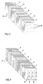
- the heat exchanger as seen in the perspective view in FIG. 4 is comprised of a plurality of plate-shaped partial elements 1 and 2 Support structure 3.
- This support structure 3 are a central first tube 4 and around Circumference of the central tube 4 distributed further second tubes 5 embedded. While the central, first tube 4 is used to pass a fluid to be cooled a second fluid, which serves as a cooling fluid, is passed through the second tube 5.
- each sub-element 1, 2 is made of one with carbon and ceramic fibers reinforced composite material.
- the sub-elements 1 and 2, as shown in Figure 1 can be seen, each differ in a different fiber orientation, as through the grain in the upper left corner of each sub-element 1, 2 is indicated.
- any Partial element can be built from individual plates with a small thickness.
- a plate part or a partial element 1, 2 is produced from a porous, carbon fiber reinforced carbon material (C / C) with so-called long fibers, or fibers that are endless in an orthotropic or quasi-isotropic orientation to the plate level.
- Such fiberboard then initially become a sub-element 1 assembled, for example by gluing with a carbon-rich Paste.
- the individual sub-elements 1, 2 are then also under each other Using this connection technique glued so that a preform results, as shown in Figure 2.
- holes 6 introduced which is possible with relatively little effort, since this pre-body is easy to work with conventional drilling techniques. With this pre-body it is a porous structure, the pores possibly being defined can be trained.
- a technique is preferably used for this, wherein the individual carbon fibers are embedded in a carbon-rich polymer are, with such a defined crack structure generated and defined under pyrolysis can be adjusted.
- the pores or the crack structure of this supporting structure of the C / C body is then infiltrated with liquid silicon, which under the influence of heat Temperatures in the range of 1410 ° C to 1700 ° C converted to silicon carbide becomes.
- the cross sections of the bores 6 can be set in a defined manner.
- the first and second tubes 4 and 5 dimensioned, but in such a way that their diameter is slight is smaller than the free bore diameter, so that a gap arises when the tube is inserted. These spaces serve as a strain compensation area, the one with an expansion compensation layer 8 made of ceramic material and / or carbon is filled.
- the expansion compensation layer 8 can thereby are formed that, before inserting the pipes into the holes, a layer is inserted from ceramic and / or carbon fibers or foils. Subsequently the pipes are inserted so that they comply with a defined Fill in the remaining space.
- first drill into the holes the first and second pipes inserted and the space with a ceramic Powder material largely filled up. in the arrangement as shown in figure 4 can be seen, the first and second tubes 4, 5 are fixed in the support structure 3, however, not embedded in a force-fitting or form-fitting manner so that it cannot be moved would be.
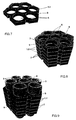
- FIG. 7 in turn a single sub-element 1, 2 of such Support structure 3 shows.
- Several such sub-elements 1, 2 are then on top of each other glued, as indicated in Figure 8 with the adhesive or connecting layers 7 is.
- the Pipes 4, 5 inserted into the bores, again with a ceramic intermediate layer, which serves as an expansion layer 8, as indicated in Figure 5.
- the modular design of the heat exchanger can be manufactured with individual sub-elements 1, 2 heat exchangers of any length, what standardized parts are used for.
- the support structure 3 as described above, in particular with a hexagonal cross-sectional shape that has sides of the same length Heat exchanger structures are constructed, as can be seen, for example, in FIG. 6 is.
- a central heat exchanger unit further module units assigned a corresponding cross-sectional shape to each side surface, so that the middle, central heat exchanger module unit completely from outer module units is surrounded.
- the tubes 4, 5 seen fixing grooves 9 formed, for example with a semicircular cross section, which is then in the construction of the heat exchanger 6 with the grooves of adjacent heat exchanger modules add to a hole into which, for example, locating pins or locating rods 10 can be used.
- the individual module units corresponding to FIG. 6 can be connected with suitable connection techniques, for example Silicon carbide layers are suitable.
- the respective tubes 4, 5 of the module units 6 can be connected to one another in a suitable manner in terms of flow be, so that there are two flow systems, the first flow system the first tubes 4 (light cross section in Figure 6), while the second pipe system (second pipes 5 - indicated dark in Figure 6) the second pipe system forms.
- the fluid to be cooled is passed through the first pipe system during the second pipe system receives the cooling fluid.
- module units such as they are shown in FIG. 5, other geometric structures can be produced, for example Heat exchangers that have a relatively large, medium cavity or complex heat exchanger structures, such as wall surfaces, which in their length and height are variable in order to adapt them to the requirements.
- Heat exchangers that have a relatively large, medium cavity or complex heat exchanger structures, such as wall surfaces, which in their length and height are variable in order to adapt them to the requirements.
- a support structure 3 which consists of fiber rovings or fabric tapes is wrapped. As from the indicated fiber course in the area of the front End faces of the wrapping structure can be seen, this support structure is in the Z direction building itself wrapped by alternating the individual fiber layers around the individual Bores 6, for the placeholder, not initially shown, during the Winding process can be used, wound. Through the crosswise course essentially around the corresponding placeholder for the one to be used inner tube 4 results in a high-strength structure. As continues to be seen is, the fibers or slivers are placed so that they are opposite each other Placeholders run and then to the neighboring placeholder be performed.
- the inner tube 4 is formed or the bore 6 for the inner tube 4 adjacent triangular cavities, in which then has a corresponding insert 11 made of a good heat-conducting material, for example a fiber ceramic can be used.
- the stretch compensation layer can initially with a structure as shown in FIG Placeholder moldings are placed around before the actual wrapping process he follows.
- the stretch compensation layer can also be used during winding by applying fibers radially around a corresponding core or area respective prefabricated first and second pipes 4, 5, which, however, are not described in more detail in Figure 10 are shown to be built.
Landscapes
- Engineering & Computer Science (AREA)
- Physics & Mathematics (AREA)
- Thermal Sciences (AREA)
- Mechanical Engineering (AREA)
- General Engineering & Computer Science (AREA)
- Geometry (AREA)
- Ceramic Engineering (AREA)
- Heat-Exchange Devices With Radiators And Conduit Assemblies (AREA)
Description
- Figuren 1 bis 4
- den schrittweisen Aufbau eines erfindungsgemäßen Wärmetauschers entsprechend einer ersten Ausführungsform,
- Figur 5
- einen Schnitt durch einen weiteren Wärmetauscher, der eine hexagonale Querschnittsstruktur aufweist,
- Figur 6
- einen Querschnitt durch einen weiteren Wärmetauscher, der aus mehreren Wärmetauscher-Modulen entsprechend Figur 5 aufgebaut ist,
- Figuren 7 bis 9
- den Wärmetauscher, wie er im Schnitt in Figur 5 dargestellt ist, in perspektivischer Darstellung in drei Verfahrensschritten seiner Herstellung, und
- Figur 10
- eine Tragestruktur vergleichbar mit derjenigen, die in Figur 8 dargestellt ist, die aus Faser-Rovings oder Gewebebändern gefertigt ist, wobei die einzelnen Faserstrukturen im vorderen Bereich angedeutet dargestellt sind.
Claims (29)
- Wärmetauscher, der mindestens ein erstes Rohr (4) zum Hindurchleiten eines zu kühlenden, Wärme abgebenden ersten Fluids und mindestens ein zweites Rohr (5) zum Hindurchleiten eines Wärme aufnehmenden zweiten Fluids aufweist, wobei zumindest das erste Rohr (4), aus einem fluiddichten, korrosions- und oxidationsbeständigen Werkstoff gebildet, in einer aus mehreren einzelnen Teilelementen (1, 2) gebildeten Tragstruktur (3) aus SiC-haltigem Werkstoff in einer Bohrung (6) der Teilelemente (1, 2) gehalten ist, dadurch gekennzeichnet, daß die Tragstruktur (3) aus aufeinandergestapelten und über eine SiC-haltige Verbindungsschicht (7) miteinander verbundenen platten- oder scheibenförmigen Teilelementen (1, 2) aus einem mit Kohlenstoff- und/oder Keramik-Fasern verstärkten Verbundwerkstoff aufgebaut ist, daß zumindest zwischen dem ersten Rohr (4) und der Tragstruktur (3) eine Dehnungsausgleichsschicht (8) aus keramischem Werkstoff und/oder Kohlenstoff angeordnet ist und daß das mindestens eine zweite Rohr (5) dem mindestens einen ersten Rohr (4) benachbart in einer in den Teilelementen (1, 2) eingebrachten Bohrung (6) gehalten ist.
- Wärmetauscher nach Anspruch 1 dadurch gekennzeichnet, daß zumindest das erste Rohr (4) aus monolithischer Keramik gebildet ist.
- Wärmetauscher nach Anspruch 2, dadurch gekennzeichnet, daß zumindest das erste Rohr (4) aus Siliciumcarbid, Siliciumnitrid, Cordierit oder Mullit gebildet ist.
- Wärmetauscher nach Anspruch 3, dadurch gekennzeichnet, daß als Siliciumcarbid ein Silicium-infiltriertes Siliciumcarbid (SiSiC) oder gesintertes Siliciumcarbid (SSiC) verwendet wird.
- Wärmetauscher nach Anspruch 1, dadurch gekennzeichnet, daß die Dehnungsausgfeichsschicht (8) im wesentlichen aus keramischem Pulver oder Kohlenstoffpulver gebildet ist.
- Wärmetauscher nach Anspruch 1, dadurch gekennzeichnet, daß die Dehnungsausgleichsschicht (8) im wesentlichen aus Keramik- und/oder Kohlenstoff-Fasern gebildet ist.
- Wärmetauscher nach Anspruch 6, dadurch gekennzeichnet, daß die Fasern bevorzugt in Umfangsrichtung der Rohre (4, 5) orientiert sind.
- Wärmetauscher nach Anspruch 1, dadurch gekennzeichnet, daß die Dehnungsausgleichsschicht (8) aus einem folienförmigen Werkstoff, insbesondere Graphit-Folie, gebildet ist.
- Wärmetauscher nach Anspruch 1, dadurch gekennzeichnet, daß die Dehnungsausgieichsschicht (8) aus einer Mischung aus faser- und pulverförmigem Werkstoff gebildet ist.
- Wärmetauscher nach Anspruch 5, dadurch gekennzeichnet, daß die Dehnungsausgleichsschicht (8) aus Bornitrid- und/oder Aluminiumnitrid-Pulver gebildet ist.
- Wärmetauscher nach Anspruch 1, dadurch gekennzeichnet, daß mindestens 50% der Fasern in den Teilelementen (1, 2) parallel zur Platten- oder Scheibenebene der als Platten oder Scheiben ausgebildeten Teilelemente (1, 2) verlaufen.
- Wärmetauscher nach Anspruch 11, dadurch gekennzeichnet, daß mindestens 90% der Fasern in den Teilelementen parallel zur Platten- oder Scheibenebene der als Platten oder Scheiben äusgebildeten Teilelemente verlaufen.
- Wärmetauscher nach Anspruch 1, dadurch gekennzeichnet, daß die Teilelemente (1, 2) aus einem kohlenstoff-faserverstärkten Verbundwerkstoff gebildet sind, wobei die Kohlenstoff-Fasern in Siliciumcarbid eingebettet sind, das durch Infiltrieren von flüssigem Silicium und unter Wärmeeinwirkung mit Kohlenstoff zu Siliciumcarbid umgewandelt ist.
- Wärmetauscher nach Anspruch 1, dadurch gekennzeichnet, daß die Faserverstärkung in den Teilelementen (1, 2) aus zweidimensionalen Geweben, Faser-Rovings oder Gewebe-Bändern gebildet ist.
- Wärmetauscher nach Anspruch 14, dadurch gekennzeichnet, daß die Faserverstärkung der Teilelemente (1, 2) aus gewickelten Faser-Rovings oder Gewebe-Bändern oder gestrickten Faser-Rovings gebildet ist (Figur 10).
- Wärmetauscher nach Anspruch 15, dadurch gekennzeichnet, daß in durch die Faserwicklung erzeugte Zwischenhohlräume diese ausfüllende Einsatzteile mit hoher, gerichteter Wärmeleitung eingesetzt oder in diesen gebildet sind.
- Wärmetauscher nach Anspruch 16, dadurch gekennzeichnet, daß die Einsatzteile aus keramischem oder keramisiertem, kohlenstoff-faserverstärktem Verbundwerkstoff gebildet sind.
- Wärmetauscher nach Anspruch 17, dadurch gekennzeichnet, daß die Einsatzteile aus SiC gebildet sind.
- Wärmetauscher nach Anspruch 1, dadurch gekennzeichnet, daß um ein zentrales, erstes Rohr (4) mehrere zweite Rohre (5) angeordnet sind.
- Wärmetauscher nach Anspruch 19, dadurch gekennzeichnet, daß die zweiten Rohre symmetrisch um das zentrale erste Rohr angeordnet sind.
- Wärmetauscher nach Anspruch 19 oder 20, dadurch gekennzeichnet, daß die Achsen der ersten und der zweiten Rohre (4, 5) parallel zueinander verlaufen.
- Wärmetauscher nach einem der Ansprüche 1 bis 21, dadurch gekennzeichnet. daß als Wärmetauscher-Moduleinheit mehrere Moduleinheiten zu einer Wärmetauschereinheit zusammengeführt sind, wobei die Querschnittsform der Moduleinheit so ausgeführt ist, daß aneinandergrenzende Moduleinheiten flächig aneinander liegen.
- Wärmetauscher nach Anspruch 22, dadurch gekennzeichnet, daß die Querschnittsform der Moduleinheiten als Polygon, vorzugsweise als Hexagon, ausgeführt ist.
- Wärmetauscher nach Anspruch 23, dadurch gekennzeichnet, daß das Polygon gleiche Seitenlängen aufweist.
- Wärmetauscher nach Anspruch 24 dadurch gekennzeichnet, daß an jeder Seite einer zentralen Moduleinheit eine weitere Moduleinheit anliegt.
- Wärmetauscher nach Anspruch 1 oder Anspruch 22, dadurch gekennzeichnet, daß in dessen Außenoberfläche Fixiernuten (9) vorgesehen sind.
- Wärmetauscher nach Anspruch 1 oder Anspruch 22, dadurch gekennzeichnet, daß die Außenoberfläche der Tragstruktur (3) mit einer Schutzschicht gegen Oxidation oder Korrosion versehen ist.
- Wärmetauscher nach Anspruch 27, dadurch gekennzeichnet, daß die Schutzschicht aus Siliciumcarbid und/oder Siliciumdioxid und/oder Molybdändisilicid gebildet ist.
- Wärmetauscher nach Anspruch 1, dadurch gekennzeichnet, daß in der Tragstruktur (3) mehrere Teilelemente (1, 2) jeweils zu Gruppen zusammenge4faßt sind und benachbarte Gruppen eine unterschiedliche Faserorientierung aufweisen.
Applications Claiming Priority (3)
| Application Number | Priority Date | Filing Date | Title |
|---|---|---|---|
| DE19730389 | 1997-07-16 | ||
| DE19730389A DE19730389C2 (de) | 1997-07-16 | 1997-07-16 | Wärmetauscher |
| PCT/EP1998/002472 WO1999004213A1 (de) | 1997-07-16 | 1998-04-25 | Wärmetauscher |
Publications (2)
| Publication Number | Publication Date |
|---|---|
| EP0996848A1 EP0996848A1 (de) | 2000-05-03 |
| EP0996848B1 true EP0996848B1 (de) | 2001-08-01 |
Family
ID=7835824
Family Applications (1)
| Application Number | Title | Priority Date | Filing Date |
|---|---|---|---|
| EP98921490A Expired - Lifetime EP0996848B1 (de) | 1997-07-16 | 1998-04-25 | Wärmetauscher |
Country Status (3)
| Country | Link |
|---|---|
| EP (1) | EP0996848B1 (de) |
| DE (2) | DE19730389C2 (de) |
| WO (1) | WO1999004213A1 (de) |
Cited By (2)
| Publication number | Priority date | Publication date | Assignee | Title |
|---|---|---|---|---|
| US9382874B2 (en) | 2010-11-18 | 2016-07-05 | Etalim Inc. | Thermal acoustic passage for a stirling cycle transducer apparatus |
| US9394851B2 (en) | 2009-07-10 | 2016-07-19 | Etalim Inc. | Stirling cycle transducer for converting between thermal energy and mechanical energy |
Families Citing this family (3)
| Publication number | Priority date | Publication date | Assignee | Title |
|---|---|---|---|---|
| US7261146B2 (en) * | 2003-01-17 | 2007-08-28 | Illinois Tool Works Inc | Conductive heat-equalizing device |
| CN107487054B (zh) * | 2016-06-12 | 2023-08-08 | 中国科学院宁波材料技术与工程研究所 | 多层复合膜、其制备方法以及作为纤维增强复合材料的连接材料的应用 |
| ES1295571Y (es) * | 2022-06-28 | 2023-02-07 | Univ Navarra Publica | Elemento de refrigeración de material cerámico electroconductor |
Family Cites Families (10)
| Publication number | Priority date | Publication date | Assignee | Title |
|---|---|---|---|---|
| GB1100832A (en) * | 1965-02-19 | 1968-01-24 | Birwelco Ltd | Improvements in or relating to heat exchangers |
| DE2758998C2 (de) * | 1977-12-30 | 1980-02-21 | Mtu Motoren- Und Turbinen-Union Muenchen Gmbh, 8000 Muenchen | Rekuperator fur den Wärmeaustausch zwischen zwei Strömungsmitteln unterschiedlicher Temperaturen |
| JPS6183897A (ja) * | 1984-09-28 | 1986-04-28 | Asahi Glass Co Ltd | セラミツクス製の熱交換体 |
| US4768586A (en) * | 1984-10-29 | 1988-09-06 | The Babcock & Wilcox Company | Ceramic heat exchangers |
| DE8600544U1 (de) * | 1986-01-11 | 1987-03-12 | Bommer, Rolf, Dipl.-Ing., 7700 Uberlingen | Wärmetauscher für Feuerungen, insbesondere Ölfeuerungen |
| DE3643749A1 (de) * | 1986-12-20 | 1988-06-30 | Hoechst Ag | Waermetauschermodul aus gebranntem keramischen material |
| DE3831812A1 (de) * | 1988-09-19 | 1990-03-22 | Interatom | Verfahren zur herstellung komplizierter bauteile aus siliziuminfiltriertem siliziumkarbid |
| EP0479832A4 (en) * | 1989-06-30 | 1993-01-07 | The Broken Hill Proprietary Company Limited | Steel composition for a composite roll and heat treatment thereof |
| DE3924411A1 (de) * | 1989-07-24 | 1991-01-31 | Hoechst Ceram Tec Ag | Rippenrohrwaermetauscher |
| FR2667591B1 (fr) | 1990-10-04 | 1993-11-05 | Ceramiques Composites | Procede d'assemblage d'objets en carbure de silicium et assemblages ainsi obtenus. |
-
1997
- 1997-07-16 DE DE19730389A patent/DE19730389C2/de not_active Expired - Fee Related
-
1998
- 1998-04-25 DE DE59801133T patent/DE59801133D1/de not_active Expired - Fee Related
- 1998-04-25 WO PCT/EP1998/002472 patent/WO1999004213A1/de not_active Ceased
- 1998-04-25 EP EP98921490A patent/EP0996848B1/de not_active Expired - Lifetime
Cited By (2)
| Publication number | Priority date | Publication date | Assignee | Title |
|---|---|---|---|---|
| US9394851B2 (en) | 2009-07-10 | 2016-07-19 | Etalim Inc. | Stirling cycle transducer for converting between thermal energy and mechanical energy |
| US9382874B2 (en) | 2010-11-18 | 2016-07-05 | Etalim Inc. | Thermal acoustic passage for a stirling cycle transducer apparatus |
Also Published As
| Publication number | Publication date |
|---|---|
| WO1999004213A1 (de) | 1999-01-28 |
| DE19730389C2 (de) | 2002-06-06 |
| DE59801133D1 (de) | 2001-09-06 |
| DE19730389A1 (de) | 1999-01-21 |
| EP0996848A1 (de) | 2000-05-03 |
Similar Documents
| Publication | Publication Date | Title |
|---|---|---|
| DE4110141C2 (de) | Keramik-Verbundaufbau und Verfahren zu dessen Herstellung | |
| WO2007110196A1 (de) | Plattenwärmetauscher, verfahren zu dessen herstellung und dessen verwendung | |
| EP1544565A2 (de) | Platten-Wärmeübertrager, Verfahren zur Herstellung eines Platten-Wärmeübertragers und keramischer Faserverbundwerkstoff, insbesondere für einen Platten-Wärmeübertrager | |
| CH643349A5 (de) | Waermetauscher aus keramischem material und verfahren zu seiner herstellung. | |
| EP0996848B1 (de) | Wärmetauscher | |
| EP2647942B1 (de) | Mikrofluidik-Bauteil und Verfahren zu seiner Herstellung | |
| WO2008034664A1 (de) | Filterelement, insbesondere zur filterung von abgasen einer brennkraftmaschine | |
| DE19937812A1 (de) | Bauelement mit einem bei erhöhter Temperatur belastbaren Teil aus Verbundwerkstoff mit Fluidumwälzkühlung | |
| WO1998053218A1 (de) | Reibeinheit in massivbauweise, insbesondere bremsscheibe, mit mehreren reibkörpern | |
| EP0225527A2 (de) | Kühlfluidkanäle aufweisende Wand, insbesondere für Gasturbinenanlagen, und Verfahren zu ihrer Herstellung | |
| DE102005005509B4 (de) | Blockwärmetauscher aus Graphit | |
| DE3042557C2 (de) | Wärmetauscher, insbesondere für Sonnenkraftwerke | |
| DE102004005832B4 (de) | Verbundwärmetauscher | |
| EP1757887A1 (de) | Wärmetauscherblock | |
| DE102011010800A1 (de) | Keramik aus präkeramischen Papier- und/oder Pappstrukturen | |
| DE3008079A1 (de) | Waermetauscher | |
| EP2917032B1 (de) | Schichtverbundwerkstoff | |
| EP2917672B1 (de) | Wabenkörper aus keramikmaterial | |
| DE102014112053A1 (de) | Rohrleitung für Heißgase und Verfahren zu deren Herstellung | |
| WO2019166493A1 (de) | Rohrbündelwärmeaustauscher sowie rohrboden und verfahren zum abdichten desselben | |
| EP1447623B1 (de) | Verfahren zur Herstellung von Wärmespeicherkörpern | |
| DE8323129U1 (de) | Keramischer Wärmetauscher | |
| DE102018125284A1 (de) | Wärmeübertragungsvorrichtung und Verfahren zum Herstellen einer Wärmeübertragungsvorrichtung | |
| DE69107795T2 (de) | Verbindungsvorrichtung zwischen zwei Körpern mit verschiedenen Dehnungskoeffizienten und Verfahren zum Herstellen derselben. | |
| DE102024127969A1 (de) | Sandwich-Bauteil und Verfahren zur Herstellung eines Sandwich-Bauteils |
Legal Events
| Date | Code | Title | Description |
|---|---|---|---|
| PUAI | Public reference made under article 153(3) epc to a published international application that has entered the european phase |
Free format text: ORIGINAL CODE: 0009012 |
|
| 17P | Request for examination filed |
Effective date: 19991015 |
|
| AK | Designated contracting states |
Kind code of ref document: A1 Designated state(s): DE FR GB |
|
| GRAG | Despatch of communication of intention to grant |
Free format text: ORIGINAL CODE: EPIDOS AGRA |
|
| 17Q | First examination report despatched |
Effective date: 20001211 |
|
| GRAG | Despatch of communication of intention to grant |
Free format text: ORIGINAL CODE: EPIDOS AGRA |
|
| GRAH | Despatch of communication of intention to grant a patent |
Free format text: ORIGINAL CODE: EPIDOS IGRA |
|
| GRAH | Despatch of communication of intention to grant a patent |
Free format text: ORIGINAL CODE: EPIDOS IGRA |
|
| GRAA | (expected) grant |
Free format text: ORIGINAL CODE: 0009210 |
|
| AK | Designated contracting states |
Kind code of ref document: B1 Designated state(s): DE FR IT |
|
| REF | Corresponds to: |
Ref document number: 59801133 Country of ref document: DE Date of ref document: 20010906 |
|
| EN | Fr: translation not filed | ||
| RBV | Designated contracting states (corrected) |
Designated state(s): DE FR IT |
|
| EN | Fr: translation not filed |
Free format text: BO 01/52 PAGES: 283, IL Y A LIEU DE SUPPRIMER: LA MENTION DE LA NON REMISE. LA REMISE EST PUBLIEE DANS LE PRESENT BOPI. |
|
| ET | Fr: translation filed | ||
| PLBE | No opposition filed within time limit |
Free format text: ORIGINAL CODE: 0009261 |
|
| STAA | Information on the status of an ep patent application or granted ep patent |
Free format text: STATUS: NO OPPOSITION FILED WITHIN TIME LIMIT |
|
| 26N | No opposition filed | ||
| PGFP | Annual fee paid to national office [announced via postgrant information from national office to epo] |
Ref country code: DE Payment date: 20070329 Year of fee payment: 10 |
|
| PGFP | Annual fee paid to national office [announced via postgrant information from national office to epo] |
Ref country code: IT Payment date: 20070609 Year of fee payment: 10 |
|
| PGFP | Annual fee paid to national office [announced via postgrant information from national office to epo] |
Ref country code: FR Payment date: 20070418 Year of fee payment: 10 |
|
| PG25 | Lapsed in a contracting state [announced via postgrant information from national office to epo] |
Ref country code: DE Free format text: LAPSE BECAUSE OF NON-PAYMENT OF DUE FEES Effective date: 20081101 |
|
| REG | Reference to a national code |
Ref country code: FR Ref legal event code: ST Effective date: 20081231 |
|
| PG25 | Lapsed in a contracting state [announced via postgrant information from national office to epo] |
Ref country code: FR Free format text: LAPSE BECAUSE OF NON-PAYMENT OF DUE FEES Effective date: 20080430 |
|
| PG25 | Lapsed in a contracting state [announced via postgrant information from national office to epo] |
Ref country code: IT Free format text: LAPSE BECAUSE OF NON-PAYMENT OF DUE FEES Effective date: 20080425 |