EP2918523B1 - Détecteur capacitif pour un rouleau et procédé de détection d'objets sur un transporteur à rouleaux - Google Patents
Détecteur capacitif pour un rouleau et procédé de détection d'objets sur un transporteur à rouleaux Download PDFInfo
- Publication number
- EP2918523B1 EP2918523B1 EP14158841.8A EP14158841A EP2918523B1 EP 2918523 B1 EP2918523 B1 EP 2918523B1 EP 14158841 A EP14158841 A EP 14158841A EP 2918523 B1 EP2918523 B1 EP 2918523B1
- Authority
- EP
- European Patent Office
- Prior art keywords
- roller
- sensor
- electrodes
- measuring
- measurement
- Prior art date
- Legal status (The legal status is an assumption and is not a legal conclusion. Google has not performed a legal analysis and makes no representation as to the accuracy of the status listed.)
- Not-in-force
Links
Images

Classifications
-
- G—PHYSICS
- G01—MEASURING; TESTING
- G01V—GEOPHYSICS; GRAVITATIONAL MEASUREMENTS; DETECTING MASSES OR OBJECTS; TAGS
- G01V3/00—Electric or magnetic prospecting or detecting; Measuring magnetic field characteristics of the earth, e.g. declination, deviation
- G01V3/02—Electric or magnetic prospecting or detecting; Measuring magnetic field characteristics of the earth, e.g. declination, deviation operating with propagation of electric current
-
- B—PERFORMING OPERATIONS; TRANSPORTING
- B65—CONVEYING; PACKING; STORING; HANDLING THIN OR FILAMENTARY MATERIAL
- B65G—TRANSPORT OR STORAGE DEVICES, e.g. CONVEYORS FOR LOADING OR TIPPING, SHOP CONVEYOR SYSTEMS OR PNEUMATIC TUBE CONVEYORS
- B65G39/00—Rollers, e.g. drive rollers, or arrangements thereof incorporated in roller-ways or other types of mechanical conveyors
- B65G39/02—Adaptations of individual rollers and supports therefor
-
- B—PERFORMING OPERATIONS; TRANSPORTING
- B65—CONVEYING; PACKING; STORING; HANDLING THIN OR FILAMENTARY MATERIAL
- B65G—TRANSPORT OR STORAGE DEVICES, e.g. CONVEYORS FOR LOADING OR TIPPING, SHOP CONVEYOR SYSTEMS OR PNEUMATIC TUBE CONVEYORS
- B65G13/00—Roller-ways
- B65G13/02—Roller-ways having driven rollers
- B65G13/06—Roller driving means
-
- B—PERFORMING OPERATIONS; TRANSPORTING
- B65—CONVEYING; PACKING; STORING; HANDLING THIN OR FILAMENTARY MATERIAL
- B65G—TRANSPORT OR STORAGE DEVICES, e.g. CONVEYORS FOR LOADING OR TIPPING, SHOP CONVEYOR SYSTEMS OR PNEUMATIC TUBE CONVEYORS
- B65G43/00—Control devices, e.g. for safety, warning or fault-correcting
- B65G43/08—Control devices operated by article or material being fed, conveyed or discharged
-
- B—PERFORMING OPERATIONS; TRANSPORTING
- B65—CONVEYING; PACKING; STORING; HANDLING THIN OR FILAMENTARY MATERIAL
- B65G—TRANSPORT OR STORAGE DEVICES, e.g. CONVEYORS FOR LOADING OR TIPPING, SHOP CONVEYOR SYSTEMS OR PNEUMATIC TUBE CONVEYORS
- B65G2203/00—Indexing code relating to control or detection of the articles or the load carriers during conveying
- B65G2203/04—Detection means
- B65G2203/042—Sensors
Definitions
- the invention relates to a capacitive sensor for a roller of a roller conveyor and a method for detecting objects located on a roller conveyor according to the preamble of claim 1 or 15, as is apparent from the DE 20 2007 015 529 U1 are known.
- Roller conveyors are generally used as roller conveyors in storage and conveyor technology. Some of the rollers have an active drive that sets them in rotation. The other passive rollers can be moved by belts from the active wheels, or the moving objects bridge such rollers due to inertia. In order to control the material flow, the roller conveyor should be monitored for the presence of objects at certain positions of the conveyor line.
- sensors such as optical, magnetic, inductive or capacitive sensors, which are mounted at the appropriate location of the conveyor line to detect the conveyed on the roller conveyor.
- the integrated sensor system comprises capacitive sensors, which are mounted so that their detection field is aligned in the direction of the conveyed material. Rollers made of plastic should be hidden, but it is not revealed how this can be achieved.
- the DE 20 2007 015 529 U1 discloses a roller for a roller conveyor with an integrated capacitive sensor, which additionally provides on a side facing away from the conveying side, a reference sensor. A switching signal in an object conveyed over the roller is then determined from a difference signal between the signal of the actual sensor and the reference sensor. It is also proposed to arrange a plurality of sensors in the longitudinal direction of the roller one behind the other.
- a problem with the conventional approaches with integrated capacitive sensors is that due to various external influences, such as irregularities in the movement of the roller through bearing clearance, temperature changes, wear or contamination, the sensor signal fluctuates to such an extent that a reliable object detection is not possible. This is also due to the reference signal of another capacitive sensor according to DE 20 2007 015 529 U1 or segmentation in the longitudinal direction of the roll is not resolved.
- the EP 2 657 663 A1 discloses a capacitive level sensor with a probe having a plurality of successive segments in a longitudinal direction and a plurality of electrodes in each segment. By determining the capacitance between electrodes of a segment, the level is measured by the location in a container where there is a transition between medium and air. This probe rests as well as the surrounding container, so that similar problems such as the described interference to moving rollers do not even ask.
- the US 2011/0116733 A1 discloses a rolling bearing assembly with a capacitive sensor unit for detecting the angular position or speed.
- the sensor unit comprises a rotor as a rotatably mounted first sensor element and a stator as a stationary second sensor element.
- a capacitor is formed, while the rotor has a gear-like structure, which is a material measure serves. Upon rotation of the rotor, the material measure modulates the capacitance and thus generates the sensor signal.
- a capacitive sensor with a large number of measuring electrodes detects objects located on a roller conveyor on the basis of capacitance changes.
- the sensor is integrated into a roll of the roller conveyor.
- the roll has a rigid axis of rotation as well as the actual roll, i. a cylindrical element that rotates about the axis of rotation while promoting objects on its outer periphery.
- the sensor is typically rigidly connected to the axis of rotation.
- the invention is based on the basic idea of rotating measuring electrodes with which the capacity variable by objects on the roll is measured.
- the measuring capacities are not affected by capacity fluctuations caused by the roll, for example by distance fluctuations or inhomogeneous material distribution of the roll.
- at least a part of the measuring electrodes is arranged co-rotating. In a preferred embodiment, all measuring electrodes are then rotating.
- the invention has the advantage that the co-rotating measuring electrodes are always located at the same point of the roller. This avoids disturbing field changes by the roller moving past the measuring electrode during its rotation, thus allowing a much more precise measurement.
- the sensor preferably has coupling electrodes, which are arranged so as to be stationary with respect to an axis of rotation of the roller and form coupling capacitances with measuring electrodes.
- the signal of the moving measuring electrodes is transferred in this way from the co-moving part of the roller in the resting with the axis of rotation part.
- first coupling electrodes form a stationary ring and second coupling electrodes form a ring co-rotating with the roller.
- the coupling capacities between stationary and co-rotating part of the roll are then considered to be concentric formed rings arranged inside each other. This geometry preserves the capacitive coupling throughout the rotation.
- the measuring electrodes are preferably formed annularly about a rotation axis of the roller. Then measuring capacitances are formed in the longitudinal direction parallel to the axis of rotation between juxtaposed rings. Despite the specific article, these and other arrangements of the measuring electrodes required in various embodiments should not preclude the existence of further measuring electrodes without the properties mentioned in each case. In principle, all possible mixtures of geometries and arrangements are possible. Homogeneous concepts with similar measuring electrodes, however, are much easier to build and evaluate.
- the annular measuring electrodes preferably act simultaneously as coupling electrodes.
- the measuring electrodes thus on the one hand form measuring capacitances with one another.
- the moving measuring electrodes also couple to coupling electrodes in the stationary part of the roller in order to transfer the signals capacitively thereto. Due to this dual function, no additional coupling electrodes are required in the co-rotating part of the roller.
- the annular measuring electrodes are preferably segmented in the circumferential direction. This results in a large number of additional measurement capacitances between the ring segments within a ring and thus an additional measurement resolution in the circumferential direction of the roll.
- the measuring electrodes preferably have elongated strips in the axial direction of the roller.
- the result is a field with a plurality of strip-shaped and aligned in the longitudinal direction parallel to the axis of rotation measuring electrodes. This results in an additional measurement resolution in the circumferential direction as with segmented rings, but with the advantage that the surface of the measuring electrodes is not bound to the width of the ring.
- the strips are preferably connected to a ring. This combines the advantages of annular coupling capacities and strip-shaped measuring capacities.
- the strips connected by a ring ensure a transformation from radial to axial direction. Due to the axial longitudinal extension, the measuring electrodes can occupy a large area and thus very accurately measure the capacity changes caused by objects.
- the sensor preferably has a plurality of segments in the axial direction, each having measuring electrodes decoupled from one another.
- it is functionally a series arrangement of several capacitive sensors along the axis of rotation, so that a better detection and greater measurement resolution in the axial direction is achieved.
- the segments can be constructed in all variants, but are preferably identical to one another in order to simplify the resulting sensor.
- an evaluation unit is provided, which is designed to determine a spatially and / or temporally resolved capacitance change from the capacitances determined by the measuring unit and then to detect or classify objects.
- a distinction is linguistically between the measuring unit, the capacitance between various pairs or groups of measuring electrodes and thus spatially resolved and at several times and thus time-resolved, and an evaluation unit for further processing of these raw data.
- both processes can also be implemented on the same chip. It is conceivable to accommodate only the measuring unit in the role and to lead the raw data to the outside and further process there in the then externally formed evaluation unit.
- the evaluation unit is preferably designed to determine geometry properties or trajectories of detected objects.
- the measuring unit provides a time-dependent matrix of the signals determined at the various measuring capacities. This can now be evaluated in very different complexity. In a simple case, it is only checked whether the sum of the changes with respect to a reference signal is sufficient to regard an object as recognized. However, by individual evaluation or different group summaries of measurement capacities and the respective time course of these signals, information is also available in order to obtain further information about the objects and to classify these according to their size or trajectory, for example.
- the evaluation unit is preferably designed to determine a reference signal in the absence of objects, in particular to cyclically or re-determine the reference signal on request.
- This reference or zero signal forms an expectation, and if an object is on the reel, on the other hand, this triggers a significant signal change, which also lasts only for the short duration of the object presence.
- many disturbances such as temperature variations or soiling, typically change the signal more slowly and with smaller amplitude.
- Such effects can therefore be taken into account cyclically or on request not only initially, but also during further operation, by redetermining the reference signal. In this case, such autocalibration preferably takes place automatically and only if no object is currently detected.
- the evaluation unit is preferably designed for rotational monitoring of the roller on the basis of the capacitance measured at a reference element mounted in the circumferential direction of the roller. Objects can only be regularly on top of the roll. The remainder of the roll is therefore available for other measurements. With a rotating roller, it is expected that a reference capacity in this peripheral area is detected once every revolution. This can be used to determine whether and at what speed the roller rotates. In addition, an error detection or an auto-calibration can use the signal at the reference capacitance, which should differ only within a tolerance of a previously learned signal at the reference capacitance.
- a roller is provided with a sensor according to the invention integrated therein.
- This role may have its own drive, so be an active role.
- the sensor preferably uses the supply and control lines of this drive.
- the sensor can also be used in a passive role without its own drive. Then the sensor needs its own connections or supplies itself and communicates wirelessly.
- the sensor is equipped with a battery or its own power generation from the rotary motion.
- inventive method can be configured in a similar manner by further features and shows similar advantages. Such further features are exemplary, but not exhaustive, in which subclaims following the independent claims are described.
- FIG. 1 shows a sectional view of a capacitive sensor 10, which is integrated in a roller 12 of a roller conveyor.
- the roller 12 has an axis of rotation 14 around which the actual rolling element 16 of the roller 12 rotates.
- the sensor 10 comprises a multiplicity of measuring capacitances, which are each formed between pairs or groups of measuring electrodes 18.
- An object located on the roller 12 influences the field 20 of the measuring capacitances and can be recognized by it.
- the measuring electrodes 18 are connected to the rolling element 16 and thus carry out its rotation with. At the axis of rotation 14 and thus with respect to the rotation of the roller 12 at rest coupling electrodes 22 are provided. As a result, further fields 24 form in coupling capacitances between the coupling electrodes 22 and the measuring electrodes 18.
- the rotating measuring capacitances are capacitively connected to the stationary part of the roller 12 in this way. With dotted lines 26 are in FIG. 1 Dividing lines between the stationary and the rotating part of the roller 12 located.
- a measuring unit 28 is provided, which is connected to the coupling electrodes 22.
- the measuring unit 28 can each drive pairs or groups of measuring electrodes 18 in order to determine measuring capacitances and thereby to detect capacitance changes due to objects.
- An evaluation unit 30 receives this raw data of the various capacitance signals determined by the measuring unit 28 and further evaluates them, for example to output a binary switching signal as a function of the presence of an object.
- the Evaluation unit 30 may be provided on a chip with the measuring unit, as a separate component and also externally outside the roller 12.
- the measuring electrodes 18 and the coupling electrodes 22 are each annular, so that they appear in two parts in the sectional view.
- the field 24 for coupling between stationary and movable part of the roller 12 is therefore located during the entire revolution of the roller 12 between two concentric rings, which are each formed by a measuring electrode 18 and a coupling electrode 22.
- the field 20 of the measuring capacitance is clamped between two adjacent rings of a pair of measuring electrodes 18.
- FIG. 2 shows an equivalent circuit diagram of the series formed by the measuring electrodes 18 and the coupling electrodes 22 of capacitors for contactless signal transmission between the stator and the rotor.
- a dotted line 26 separates the stationary and moving parts of the roller 12.
- the measuring unit 28 can drive a plurality of measuring channels, wherein FIG. 2 purely by way of example shows three measuring channels.
- Each measuring channel has a series connection of a coupling capacitor 32 for signal guidance in the rotating system, a depending on the presence of objects variable measuring capacitor 34 in the rotating system and in turn a coupling capacitor 36 for signal guidance from the rotating system.
- FIG. 2 shows an equivalent circuit diagram of the series formed by the measuring electrodes 18 and the coupling electrodes 22 of capacitors for contactless signal transmission between the stator and the rotor.
- a dotted line 26 separates the stationary and moving parts of the roller 12.
- the measuring unit 28 can drive a plurality of measuring channels, wherein FIG. 2 purely by way of example shows three measuring channels.
- Each measuring channel has
- the annular measuring electrodes 18 have a dual function at the same time as a counterpart of the coupling electrodes 22 for forming the coupling capacitors 32, 36.
- the coupling electrodes 22 for forming the coupling capacitors 32, 36.
- the equivalent circuit diagram according to FIG. 2 provided conductive electrodes.
- the measuring principle is therefore based on the change in the measuring capacity of the measuring capacitor 34, which is connected via two coupling capacitors 32, 36 for gap bridging between the rotor and stator of the roller 12. Promoted objects detune the electric field 20 and change this measuring capacity. Strictly speaking, a change in the total capacitance of the series connection of the capacitors 32, 34, 36 is measured, but the relevant changes contribute to the measuring capacitor 34.
- FIG. 1 an exemplary geometry has been shown in which several signals are detected over several pairs of annular measuring electrodes 18 over the longitudinal extent of the roller 12 parallel to the axis of rotation 14. This achieves an axial spatial resolution.
- a spatial resolution in the circumferential direction can also be achieved.
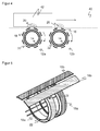
- FIG. 3 shows a three-dimensional exterior view of the measuring electrodes 18 in another embodiment.
- a plurality of mutually decoupled segments 38a-d are provided here in the axial direction.
- a plurality of measuring electrodes 18 are distributed over the circumferential direction, for example for differential compensation within a segment 38a-d. This creates a matrix of measuring capacitances with spatial resolution in the axial direction and in the circumferential direction.
- the number of segments 38a-d and the measuring electrodes 18 within the segments 38a-d varies depending on the embodiment and results from various constraints and requirements, such as roll diameter, spatial resolution, sensitivity of the capacitive measurement, the required robustness of the capacitive measurement against deposit formation on the roll 12, the required capacity of the measuring capacitors 34 and the like.
- the representation of the FIG. 3 insofar as it is artificial, as the measuring electrodes 18 are usually arranged below the actual rolling element 16 and thus are not visible from the outside. Measuring electrodes 18 preferably do not come into direct contact with conveyed objects; instead, the rolling element 16 better withstands such loads. Of course, the rolling element 16 may not form a metallic surface and a metallic grid, since otherwise the measuring electrodes 18 would be shielded from the objects.
- the roller thus preferably has a nonconductive, dielectric material which is optimized against abrasion.
- FIG. 4 shows a sectional view of a roller conveyor 40 with purely exemplary only two illustrated rollers 12a-b with integrated sensor.
- object 42 which is recognized by the changes of the field 20.
- annular coupling electrodes 22 are provided in the rollers 12a-b concentric with the axis of rotation 14 .
- measuring electrodes 18 are arranged in a likewise annular arrangement, wherein over the circumference a plurality of measuring electrodes 18 is distributed.
- Each of these measuring electrodes 18 either forms a ring segment or is strip-shaped in the axial direction, ie in FIG. 4 in a direction perpendicular to the paper plane. This can be formed in the circumferential direction by pairwise response of adjacent measuring electrodes 18, a plurality of measuring capacitances to detect spatially resolved signals in the circumferential direction.
- FIG. 5 shows a further geometric embodiment of the coupling electrodes 22 and the measuring electrodes 18.
- the rings 18 are provided so that the field 20 is formed in the axial direction between the rings and not as in FIG. 4 in the axial direction between the strips 18b.
- Which arrangement is more advantageous depends on application-specific factors such as object size, detection width and required capacitive sensitivity.
- FIG. 4 Again, the separation between the stationary and rotating part between the coupling electrodes 22 and the measuring electrodes 18, in this case between the concentric inner and outer rings. The measuring electrodes 18 thus rotate about the coupling electrodes 22.
- the measuring electrode 18 can be strictly subdivided into the respective ring 18a, which forms a coupling capacitor 32, 36 with a coupling electrode 22, and a strip 18b, wherein each pair of strips 18b forms a measuring capacitor 34 ,
- each strip 18b is only conductively connected to exactly one ring 18a, since otherwise the measuring capacitor 34 would be short-circuited.
- the measuring unit 28 supplies spatially resolved measured data in a plurality of measuring channels in the axial direction and / or in the circumferential direction, which can be further evaluated algorithmically in the evaluation unit 30.
- the capacitive signals are evaluated individually or in summary in groups.
- more complex evaluations are also conceivable, for example that an object signal only takes place if at least n measurement channels respond to the object 42 in a defined sequence and chronological sequence.
- the evaluation can classify objects 42 from their position and size information by the respective size of the capacitance changes and the number of influenced measuring channels in the axial direction and the number and duration of the influence of Measuring channels are taken into account in the circumferential direction. This provides useful additional information about the objects 42, but can also be used to distinguish objects 42 from objec- tive objects and to hide the latter.
- a silence signal is monitored in the absence of objects 42 by continuous evaluation of the measurement channels.
- slow changes can be detected and readjusted to dynamically minimize influences such as temperature or tolerances.
- sudden changes can be compensated by the measurement information is tracked on rotation of the roller 12 over at least one extent long and a plausibility check takes place.
- the evaluation unit 30 can derive the transport direction of the objects 42. Furthermore, it can be determined whether the roller 12 rotates at all. For this purpose, for example, a reference element is there attached to the outer circumference of the roller 12, where no objects 42 are promoted, so for example below. This reference element is expected to have a regular effect on the measuring capacitors 34 located in each case. If this is not the case, it is possible to conclude that the roll 12 is at a standstill and, in addition, other disturbances can also be detected and reported or recalibrated in response to unexpected changes in the signal measured at the reference element.
Landscapes
- Engineering & Computer Science (AREA)
- Mechanical Engineering (AREA)
- Life Sciences & Earth Sciences (AREA)
- Environmental & Geological Engineering (AREA)
- Geology (AREA)
- Remote Sensing (AREA)
- Physics & Mathematics (AREA)
- General Life Sciences & Earth Sciences (AREA)
- General Physics & Mathematics (AREA)
- Geophysics (AREA)
- Measurement Of Length, Angles, Or The Like Using Electric Or Magnetic Means (AREA)
- Transmission And Conversion Of Sensor Element Output (AREA)
- Investigating Or Analyzing Materials By The Use Of Electric Means (AREA)
Claims (15)
- Détecteur capacitif (10) pour un rouleau (12) d'une voie à rouleaux, qui comprend une pluralité d'électrodes de mesure (18) ainsi qu'une unité de mesure (28) pour déterminer des capacités entre électrodes de mesure (18), afin de reconnaître un objet (42) qui se trouve sur la voie à rouleaux au moyen de modifications de capacité,
caractérisé en ce que
au moins une partie des électrodes de mesure (18) sont agencées de manière à tourner conjointement avec le rouleau (12, 16) et forment ainsi des capacités de mesure rotatives entre les électrodes de mesure (18) qui tournent conjointement. - Détecteur (10) selon la revendication 1,
qui comprend des électrodes de couplage (22), qui sont agencées en repos par rapport à un axe de rotation (14) du rouleau (12) et qui forment des capacités de couplage (32, 36) avec des électrodes de mesure (18). - Détecteur (10) selon la revendication 2,
dans lequel des premières électrodes de couplage (22) forment un anneau stationnaire, et des secondes électrodes de couplage (22) forment un anneau qui tourne conjointement avec le rouleau (12). - Détecteur (10) selon l'une des revendications précédentes,
dans lequel les électrodes de mesure (18) sont réalisées en formant un anneau autour d'un axe de rotation (14) du rouleau (12). - Détecteur (10) selon la revendication 4,
dans lequel les électrodes de mesure en forme d'anneau (13) font simultanément office d'électrodes de couplage (22). - Détecteur (10) selon la revendication 4 ou 5,
dans lequel les électrodes de mesure en forme d'anneau (18) sont segmentées en direction périphérique. - Détecteur (10) selon l'une des revendications précédentes,
dans lequel les électrodes de mesure (18) comportent des rubans allongés en longueur (18b) en direction axiale du rouleau (12). - Détecteur (10) selon la revendication 7,
dans lequel les rubans (18b) sont reliés à un anneau (18a). - Détecteur (10) selon l'une des revendications précédentes,
qui comprend en direction axiale plusieurs segments (18a-b) avec des électrodes de mesure (18) respectivement découplées les unes des autres. - Détecteur (10) selon l'une des revendications précédentes,
dans lequel il est prévu une unité d'évaluation (30) qui est réalisée pour détecter une modification de capacité à résolution locale et/ou à résolution temporelle à partir des capacités déterminées par l'unité de mesure (28), et ensuite pour détecter des objets (42) ou les classifier. - Détecteur (10) selon la revendication 10,
dans lequel l'unité d'évaluation (30) est réalisée pour déterminer des propriétés géométriques ou des trajectoires de déplacement des objets détectés (42). - Détecteur (10) selon la revendication 10 ou 11,
dans lequel l'unité d'évaluation (30) est réalisée pour déterminer un signal de référence en l'absence d'objets, et en particulier pour déterminer à nouveau le signal de référence de façon cyclique ou sur requête. - Détecteur (10) selon l'une des revendications 10 à 12,
dans lequel l'unité d'évaluation (30) est réalisée pour une surveillance en rotation du rouleau (12) au moyen de la capacité mesurée avec un élément de référence rapporté en direction périphérique du rouleau (12). - Rouleau (12) comprenant un détecteur (10) selon l'une des revendications précédentes.
- Procédé pour reconnaître des objets (42) qui se trouvent sur une voie à rouleaux, dans lequel on mesure, dans un rouleau (12) de la voie à rouleaux, des capacités entre une pluralité d'électrodes de mesure (18), et on reconnaît la présence d'un objet (42) au moyen de variations de capacité,
caractérisé en ce que
on mesure des capacités entre des électrodes de mesure (18), qui tournent conjointement avec le rouleau (12, 16) et qui forment ainsi des capacités de mesure en rotation entre les électrodes de mesure (18) en rotation conjointe.
Priority Applications (2)
| Application Number | Priority Date | Filing Date | Title |
|---|---|---|---|
| EP14158841.8A EP2918523B1 (fr) | 2014-03-11 | 2014-03-11 | Détecteur capacitif pour un rouleau et procédé de détection d'objets sur un transporteur à rouleaux |
| US14/608,590 US9568631B2 (en) | 2014-03-11 | 2015-01-29 | Capacitive sensor for a roller and method for recognizing objects at a roller track |
Applications Claiming Priority (1)
| Application Number | Priority Date | Filing Date | Title |
|---|---|---|---|
| EP14158841.8A EP2918523B1 (fr) | 2014-03-11 | 2014-03-11 | Détecteur capacitif pour un rouleau et procédé de détection d'objets sur un transporteur à rouleaux |
Publications (2)
| Publication Number | Publication Date |
|---|---|
| EP2918523A1 EP2918523A1 (fr) | 2015-09-16 |
| EP2918523B1 true EP2918523B1 (fr) | 2016-02-03 |
Family
ID=50241195
Family Applications (1)
| Application Number | Title | Priority Date | Filing Date |
|---|---|---|---|
| EP14158841.8A Not-in-force EP2918523B1 (fr) | 2014-03-11 | 2014-03-11 | Détecteur capacitif pour un rouleau et procédé de détection d'objets sur un transporteur à rouleaux |
Country Status (2)
| Country | Link |
|---|---|
| US (1) | US9568631B2 (fr) |
| EP (1) | EP2918523B1 (fr) |
Families Citing this family (2)
| Publication number | Priority date | Publication date | Assignee | Title |
|---|---|---|---|---|
| DE102019117319A1 (de) * | 2019-06-27 | 2020-12-31 | Gerd Küpper | Sensorrolle für Förder- und Lagertechnische Einrichtungen zur Beförderung von Stückgut |
| EP3797899A1 (fr) * | 2019-09-27 | 2021-03-31 | Primetals Technologies Austria GmbH | Dispositif et procédé de détection d'un mouvement d'un corps dans une installation industrielle |
Family Cites Families (7)
| Publication number | Priority date | Publication date | Assignee | Title |
|---|---|---|---|---|
| DE10131019A1 (de) | 2001-06-05 | 2002-12-19 | Siemens Ag | Mess- und Erfassungsrolle |
| DE10133216B4 (de) * | 2001-07-09 | 2005-01-27 | Tecpharma Licensing Ag | Positionsdetektion |
| US7023684B1 (en) * | 2005-06-01 | 2006-04-04 | Jack Chen | Variable position sensor employing capacitance |
| DE202007015529U1 (de) * | 2007-11-08 | 2009-03-26 | Sick Ag | Rolle für eine Rollenbahn |
| DE102009044542B3 (de) * | 2009-11-16 | 2011-05-19 | Ina - Drives & Mechatronics Gmbh & Co. Ohg | Wälzlager mit einer Sensoreinheit |
| US8919539B2 (en) * | 2010-02-23 | 2014-12-30 | Sew-Eurodrive Gmbh & Co. Kg | Roller drive and method for controlling a system |
| EP2657663A1 (fr) | 2012-04-27 | 2013-10-30 | Sick AG | Capteur du niveau de remplissage capacitif |
-
2014
- 2014-03-11 EP EP14158841.8A patent/EP2918523B1/fr not_active Not-in-force
-
2015
- 2015-01-29 US US14/608,590 patent/US9568631B2/en not_active Expired - Fee Related
Also Published As
| Publication number | Publication date |
|---|---|
| EP2918523A1 (fr) | 2015-09-16 |
| US9568631B2 (en) | 2017-02-14 |
| US20150260871A1 (en) | 2015-09-17 |
Similar Documents
| Publication | Publication Date | Title |
|---|---|---|
| DE102009044542B3 (de) | Wälzlager mit einer Sensoreinheit | |
| EP0258725B1 (fr) | Transmetteur rotatif capacitif pour la commande et le positionnement d'objets en mouvement | |
| DE102016116113A1 (de) | Lager und Verfahren zur Verschleißüberwachung und/oder Lastmessung | |
| EP2622311B1 (fr) | Résolveur capacitif | |
| DE3617335C2 (fr) | ||
| EP3475196B1 (fr) | Dispositif de transport et procédé permettant de commander et de contrôler l'expansion d'un dispositif de transport | |
| EP3227162B1 (fr) | Système de capteurs pour volant, volant avec un tel système et procécé pour opérer un tel système | |
| WO2018041704A1 (fr) | Élément roulant destiné à être utilisé dans un palier à roulement | |
| DE102010045912B4 (de) | Rotierbares Wälzlager | |
| EP2153077A1 (fr) | Dispositif de détection et de surveillance des dommages sur des paliers à roulement | |
| EP2095078A2 (fr) | Dispositif de codage angulaire capacitif et chargeur enfichable pour machines d'équipement de cartes de circuit imprimé | |
| DE102015208444B4 (de) | Sensoranordnung zur Detektion einer Dehnung, Last, Temperatur, Vibration und/oder Bewegungsrichtung wenigstens eines Wälzkörpers sowie ein Wälzlager mit der Sensoranordnung | |
| EP2918523B1 (fr) | Détecteur capacitif pour un rouleau et procédé de détection d'objets sur un transporteur à rouleaux | |
| EP3857197A1 (fr) | Corps de roulement équipé d'un capteur et destiné à être utilisé dans un palier à roulement | |
| AT505013B1 (de) | Vorrichtung zur messung von fördereigenschaften in rohren | |
| EP2553475B1 (fr) | Module de palier comportant un palier | |
| EP4082715B1 (fr) | Broche en travail comprenant un dispositif de surveillance et procédé de surveillance d'une broche en travail | |
| DE102014218982A1 (de) | Sensoranordnung zur Weg- und/oder Winkelmessung | |
| DE102007020940B3 (de) | Vorrichtung zum Erkennen und Überwachen von Schäden bei Wälzlagern | |
| DE102013102237B4 (de) | Kapazitiver Positionsschalter | |
| EP4048612B1 (fr) | Procédé de production d'anhydro-1,6 sucres | |
| DE202010011758U1 (de) | Sensoranordnung zur kontaktlosen Ermittlung der aktuellen Winkelstellung einer Welle | |
| DE10006503A1 (de) | Radzählwerk | |
| DE102013102543A1 (de) | Drehgeber mit geringer Leistungsaufnahme | |
| EP2415697B1 (fr) | Dispositif de transport et son procédé de surveillance |
Legal Events
| Date | Code | Title | Description |
|---|---|---|---|
| PUAI | Public reference made under article 153(3) epc to a published international application that has entered the european phase |
Free format text: ORIGINAL CODE: 0009012 |
|
| 17P | Request for examination filed |
Effective date: 20141016 |
|
| AK | Designated contracting states |
Kind code of ref document: A1 Designated state(s): AL AT BE BG CH CY CZ DE DK EE ES FI FR GB GR HR HU IE IS IT LI LT LU LV MC MK MT NL NO PL PT RO RS SE SI SK SM TR |
|
| AX | Request for extension of the european patent |
Extension state: BA ME |
|
| GRAP | Despatch of communication of intention to grant a patent |
Free format text: ORIGINAL CODE: EPIDOSNIGR1 |
|
| INTG | Intention to grant announced |
Effective date: 20151009 |
|
| GRAS | Grant fee paid |
Free format text: ORIGINAL CODE: EPIDOSNIGR3 |
|
| GRAA | (expected) grant |
Free format text: ORIGINAL CODE: 0009210 |
|
| AK | Designated contracting states |
Kind code of ref document: B1 Designated state(s): AL AT BE BG CH CY CZ DE DK EE ES FI FR GB GR HR HU IE IS IT LI LT LU LV MC MK MT NL NO PL PT RO RS SE SI SK SM TR |
|
| REG | Reference to a national code |
Ref country code: GB Ref legal event code: FG4D Free format text: NOT ENGLISH |
|
| REG | Reference to a national code |
Ref country code: AT Ref legal event code: REF Ref document number: 773583 Country of ref document: AT Kind code of ref document: T Effective date: 20160215 Ref country code: CH Ref legal event code: EP |
|
| REG | Reference to a national code |
Ref country code: IE Ref legal event code: FG4D Free format text: LANGUAGE OF EP DOCUMENT: GERMAN |
|
| REG | Reference to a national code |
Ref country code: DE Ref legal event code: R096 Ref document number: 502014000334 Country of ref document: DE |
|
| REG | Reference to a national code |
Ref country code: LT Ref legal event code: MG4D Ref country code: NL Ref legal event code: MP Effective date: 20160203 |
|
| PG25 | Lapsed in a contracting state [announced via postgrant information from national office to epo] |
Ref country code: NO Free format text: LAPSE BECAUSE OF FAILURE TO SUBMIT A TRANSLATION OF THE DESCRIPTION OR TO PAY THE FEE WITHIN THE PRESCRIBED TIME-LIMIT Effective date: 20160503 Ref country code: GR Free format text: LAPSE BECAUSE OF FAILURE TO SUBMIT A TRANSLATION OF THE DESCRIPTION OR TO PAY THE FEE WITHIN THE PRESCRIBED TIME-LIMIT Effective date: 20160504 Ref country code: IT Free format text: LAPSE BECAUSE OF FAILURE TO SUBMIT A TRANSLATION OF THE DESCRIPTION OR TO PAY THE FEE WITHIN THE PRESCRIBED TIME-LIMIT Effective date: 20160203 Ref country code: FI Free format text: LAPSE BECAUSE OF FAILURE TO SUBMIT A TRANSLATION OF THE DESCRIPTION OR TO PAY THE FEE WITHIN THE PRESCRIBED TIME-LIMIT Effective date: 20160203 Ref country code: ES Free format text: LAPSE BECAUSE OF FAILURE TO SUBMIT A TRANSLATION OF THE DESCRIPTION OR TO PAY THE FEE WITHIN THE PRESCRIBED TIME-LIMIT Effective date: 20160203 Ref country code: HR Free format text: LAPSE BECAUSE OF FAILURE TO SUBMIT A TRANSLATION OF THE DESCRIPTION OR TO PAY THE FEE WITHIN THE PRESCRIBED TIME-LIMIT Effective date: 20160203 |
|
| PG25 | Lapsed in a contracting state [announced via postgrant information from national office to epo] |
Ref country code: LV Free format text: LAPSE BECAUSE OF FAILURE TO SUBMIT A TRANSLATION OF THE DESCRIPTION OR TO PAY THE FEE WITHIN THE PRESCRIBED TIME-LIMIT Effective date: 20160203 Ref country code: PT Free format text: LAPSE BECAUSE OF FAILURE TO SUBMIT A TRANSLATION OF THE DESCRIPTION OR TO PAY THE FEE WITHIN THE PRESCRIBED TIME-LIMIT Effective date: 20160603 Ref country code: NL Free format text: LAPSE BECAUSE OF FAILURE TO SUBMIT A TRANSLATION OF THE DESCRIPTION OR TO PAY THE FEE WITHIN THE PRESCRIBED TIME-LIMIT Effective date: 20160203 Ref country code: PL Free format text: LAPSE BECAUSE OF FAILURE TO SUBMIT A TRANSLATION OF THE DESCRIPTION OR TO PAY THE FEE WITHIN THE PRESCRIBED TIME-LIMIT Effective date: 20160203 Ref country code: RS Free format text: LAPSE BECAUSE OF FAILURE TO SUBMIT A TRANSLATION OF THE DESCRIPTION OR TO PAY THE FEE WITHIN THE PRESCRIBED TIME-LIMIT Effective date: 20160203 Ref country code: IS Free format text: LAPSE BECAUSE OF FAILURE TO SUBMIT A TRANSLATION OF THE DESCRIPTION OR TO PAY THE FEE WITHIN THE PRESCRIBED TIME-LIMIT Effective date: 20160603 Ref country code: LT Free format text: LAPSE BECAUSE OF FAILURE TO SUBMIT A TRANSLATION OF THE DESCRIPTION OR TO PAY THE FEE WITHIN THE PRESCRIBED TIME-LIMIT Effective date: 20160203 Ref country code: SE Free format text: LAPSE BECAUSE OF FAILURE TO SUBMIT A TRANSLATION OF THE DESCRIPTION OR TO PAY THE FEE WITHIN THE PRESCRIBED TIME-LIMIT Effective date: 20160203 Ref country code: BE Free format text: LAPSE BECAUSE OF NON-PAYMENT OF DUE FEES Effective date: 20160331 |
|
| PG25 | Lapsed in a contracting state [announced via postgrant information from national office to epo] |
Ref country code: EE Free format text: LAPSE BECAUSE OF FAILURE TO SUBMIT A TRANSLATION OF THE DESCRIPTION OR TO PAY THE FEE WITHIN THE PRESCRIBED TIME-LIMIT Effective date: 20160203 Ref country code: DK Free format text: LAPSE BECAUSE OF FAILURE TO SUBMIT A TRANSLATION OF THE DESCRIPTION OR TO PAY THE FEE WITHIN THE PRESCRIBED TIME-LIMIT Effective date: 20160203 |
|
| REG | Reference to a national code |
Ref country code: DE Ref legal event code: R097 Ref document number: 502014000334 Country of ref document: DE |
|
| PG25 | Lapsed in a contracting state [announced via postgrant information from national office to epo] |
Ref country code: SK Free format text: LAPSE BECAUSE OF FAILURE TO SUBMIT A TRANSLATION OF THE DESCRIPTION OR TO PAY THE FEE WITHIN THE PRESCRIBED TIME-LIMIT Effective date: 20160203 Ref country code: CZ Free format text: LAPSE BECAUSE OF FAILURE TO SUBMIT A TRANSLATION OF THE DESCRIPTION OR TO PAY THE FEE WITHIN THE PRESCRIBED TIME-LIMIT Effective date: 20160203 Ref country code: RO Free format text: LAPSE BECAUSE OF FAILURE TO SUBMIT A TRANSLATION OF THE DESCRIPTION OR TO PAY THE FEE WITHIN THE PRESCRIBED TIME-LIMIT Effective date: 20160203 Ref country code: SM Free format text: LAPSE BECAUSE OF FAILURE TO SUBMIT A TRANSLATION OF THE DESCRIPTION OR TO PAY THE FEE WITHIN THE PRESCRIBED TIME-LIMIT Effective date: 20160203 |
|
| PLBE | No opposition filed within time limit |
Free format text: ORIGINAL CODE: 0009261 |
|
| STAA | Information on the status of an ep patent application or granted ep patent |
Free format text: STATUS: NO OPPOSITION FILED WITHIN TIME LIMIT |
|
| REG | Reference to a national code |
Ref country code: IE Ref legal event code: MM4A |
|
| REG | Reference to a national code |
Ref country code: FR Ref legal event code: ST Effective date: 20161130 |
|
| 26N | No opposition filed |
Effective date: 20161104 |
|
| PG25 | Lapsed in a contracting state [announced via postgrant information from national office to epo] |
Ref country code: IE Free format text: LAPSE BECAUSE OF NON-PAYMENT OF DUE FEES Effective date: 20160311 Ref country code: FR Free format text: LAPSE BECAUSE OF NON-PAYMENT OF DUE FEES Effective date: 20160404 |
|
| PG25 | Lapsed in a contracting state [announced via postgrant information from national office to epo] |
Ref country code: SI Free format text: LAPSE BECAUSE OF FAILURE TO SUBMIT A TRANSLATION OF THE DESCRIPTION OR TO PAY THE FEE WITHIN THE PRESCRIBED TIME-LIMIT Effective date: 20160203 Ref country code: BG Free format text: LAPSE BECAUSE OF FAILURE TO SUBMIT A TRANSLATION OF THE DESCRIPTION OR TO PAY THE FEE WITHIN THE PRESCRIBED TIME-LIMIT Effective date: 20160503 |
|
| PG25 | Lapsed in a contracting state [announced via postgrant information from national office to epo] |
Ref country code: MT Free format text: LAPSE BECAUSE OF FAILURE TO SUBMIT A TRANSLATION OF THE DESCRIPTION OR TO PAY THE FEE WITHIN THE PRESCRIBED TIME-LIMIT Effective date: 20160203 |
|
| REG | Reference to a national code |
Ref country code: CH Ref legal event code: PL |
|
| PG25 | Lapsed in a contracting state [announced via postgrant information from national office to epo] |
Ref country code: LI Free format text: LAPSE BECAUSE OF NON-PAYMENT OF DUE FEES Effective date: 20170331 Ref country code: CH Free format text: LAPSE BECAUSE OF NON-PAYMENT OF DUE FEES Effective date: 20170331 |
|
| PG25 | Lapsed in a contracting state [announced via postgrant information from national office to epo] |
Ref country code: HU Free format text: LAPSE BECAUSE OF FAILURE TO SUBMIT A TRANSLATION OF THE DESCRIPTION OR TO PAY THE FEE WITHIN THE PRESCRIBED TIME-LIMIT; INVALID AB INITIO Effective date: 20140311 |
|
| PG25 | Lapsed in a contracting state [announced via postgrant information from national office to epo] |
Ref country code: LU Free format text: LAPSE BECAUSE OF NON-PAYMENT OF DUE FEES Effective date: 20160311 Ref country code: MC Free format text: LAPSE BECAUSE OF FAILURE TO SUBMIT A TRANSLATION OF THE DESCRIPTION OR TO PAY THE FEE WITHIN THE PRESCRIBED TIME-LIMIT Effective date: 20160203 Ref country code: MK Free format text: LAPSE BECAUSE OF FAILURE TO SUBMIT A TRANSLATION OF THE DESCRIPTION OR TO PAY THE FEE WITHIN THE PRESCRIBED TIME-LIMIT Effective date: 20160203 Ref country code: CY Free format text: LAPSE BECAUSE OF FAILURE TO SUBMIT A TRANSLATION OF THE DESCRIPTION OR TO PAY THE FEE WITHIN THE PRESCRIBED TIME-LIMIT Effective date: 20160203 |
|
| PG25 | Lapsed in a contracting state [announced via postgrant information from national office to epo] |
Ref country code: TR Free format text: LAPSE BECAUSE OF FAILURE TO SUBMIT A TRANSLATION OF THE DESCRIPTION OR TO PAY THE FEE WITHIN THE PRESCRIBED TIME-LIMIT Effective date: 20160203 Ref country code: AL Free format text: LAPSE BECAUSE OF FAILURE TO SUBMIT A TRANSLATION OF THE DESCRIPTION OR TO PAY THE FEE WITHIN THE PRESCRIBED TIME-LIMIT Effective date: 20160203 |
|
| GBPC | Gb: european patent ceased through non-payment of renewal fee |
Effective date: 20180311 |
|
| PG25 | Lapsed in a contracting state [announced via postgrant information from national office to epo] |
Ref country code: GB Free format text: LAPSE BECAUSE OF NON-PAYMENT OF DUE FEES Effective date: 20180311 |
|
| PGFP | Annual fee paid to national office [announced via postgrant information from national office to epo] |
Ref country code: AT Payment date: 20220318 Year of fee payment: 9 |
|
| PGFP | Annual fee paid to national office [announced via postgrant information from national office to epo] |
Ref country code: DE Payment date: 20230320 Year of fee payment: 10 |
|
| REG | Reference to a national code |
Ref country code: AT Ref legal event code: MM01 Ref document number: 773583 Country of ref document: AT Kind code of ref document: T Effective date: 20230311 |
|
| PG25 | Lapsed in a contracting state [announced via postgrant information from national office to epo] |
Ref country code: AT Free format text: LAPSE BECAUSE OF NON-PAYMENT OF DUE FEES Effective date: 20230311 |
|
| REG | Reference to a national code |
Ref country code: DE Ref legal event code: R119 Ref document number: 502014000334 Country of ref document: DE |
|
| PG25 | Lapsed in a contracting state [announced via postgrant information from national office to epo] |
Ref country code: DE Free format text: LAPSE BECAUSE OF NON-PAYMENT OF DUE FEES Effective date: 20241001 |
|
| PG25 | Lapsed in a contracting state [announced via postgrant information from national office to epo] |
Ref country code: DE Free format text: LAPSE BECAUSE OF NON-PAYMENT OF DUE FEES Effective date: 20241001 |