EP2918741A1 - Blocage de refoulement - Google Patents
Blocage de refoulement Download PDFInfo
- Publication number
- EP2918741A1 EP2918741A1 EP15000357.2A EP15000357A EP2918741A1 EP 2918741 A1 EP2918741 A1 EP 2918741A1 EP 15000357 A EP15000357 A EP 15000357A EP 2918741 A1 EP2918741 A1 EP 2918741A1
- Authority
- EP
- European Patent Office
- Prior art keywords
- jet nozzle
- opening
- nozzle
- jet
- membrane
- Prior art date
- Legal status (The legal status is an assumption and is not a legal conclusion. Google has not performed a legal analysis and makes no representation as to the accuracy of the status listed.)
- Granted
Links
Images





Classifications
-
- E—FIXED CONSTRUCTIONS
- E03—WATER SUPPLY; SEWERAGE
- E03D—WATER-CLOSETS OR URINALS WITH FLUSHING DEVICES; FLUSHING VALVES THEREFOR
- E03D9/00—Sanitary or other accessories for lavatories ; Devices for cleaning or disinfecting the toilet room or the toilet bowl; Devices for eliminating smells
- E03D9/08—Devices in the bowl producing upwardly-directed sprays; Modifications of the bowl for use with such devices ; Bidets; Combinations of bowls with urinals or bidets; Hot-air or other devices mounted in or on the bowl, urinal or bidet for cleaning or disinfecting
-
- E—FIXED CONSTRUCTIONS
- E03—WATER SUPPLY; SEWERAGE
- E03C—DOMESTIC PLUMBING INSTALLATIONS FOR FRESH WATER OR WASTE WATER; SINKS
- E03C1/00—Domestic plumbing installations for fresh water or waste water; Sinks
- E03C1/02—Plumbing installations for fresh water
- E03C1/10—Devices for preventing contamination of drinking-water pipes, e.g. means for aerating self-closing flushing valves
- E03C1/102—Devices for preventing contamination of drinking-water pipes, e.g. means for aerating self-closing flushing valves using an air gap device
Definitions
- the invention relates to a backflow barrier which has a jet nozzle which can be connected to an inlet and a catching part which has to capture the liquid jet coming from the jet nozzle via a free jet path and which can be connected or connected to a drain, and with an outlet arranged below the free jet path, which outlet has to discharge a liquid subset not captured by the catching part.
- the known backflow barrier has a housing in which a jet nozzle is provided.
- the jet nozzle In order to connect the jet nozzle to the general drinking water supply network, the jet nozzle can be connected to a housing inlet.
- a catching part In the housing, a catching part is provided, which has to capture the coming of the jet nozzle via a free jet path liquid jet.
- the catching part in the housing can be connected to a housing outlet.
- Below the jet section located between the jet nozzle and the trapping part there is arranged a housing outlet which has to discharge an amount of liquid, not trapped by the trapping part, out of the housing interior.
- the pressure energy of the inflowing water from the supply network in the jet nozzle is converted into kinetic energy to bring the water jet on the short free jet distance to the atmosphere in combination and subsequently to at least partially convert the kinetic energy of the water jet in the area of the trapping part, also referred to as a diffuser, into pressure energy which is required, for example, for the cleaning jet of the sub-showers.
- the jet nozzle and the capture part are to be adapted to each other and to the specific conditions of the respective supply network . It is a disadvantage that the prior art backflow barriers are indeed optimized in view of the prevailing conditions in a particular supply network, but that these backflow barriers may not provide optimal performance under different conditions. It is always effective to ensure that the pipe network is not contaminated with dirty water.
- the optimized coordination between the jet nozzle and the catching part can be impaired if, in particular, dirt or calcium deposits form on the nozzle opening of the catching part. Such lime deposits are possible if the water droplets remaining at the nozzle opening of the jet nozzle evaporate and a lime residue originally contained in the water remains behind.
- the achievement of this object is in the backflow barrier of the type mentioned in particular in that the jet nozzle is displaceably guided in the backflow barrier and displaced from a standby position into a spraying position, in which injection position the jet nozzle with its nozzle orifice delimiting a nozzle section Through opening pierces, which is provided in an elastic membrane or closed in the ready position by a flap.
- the jet nozzle is guided displaceably in the return flow barrier and displaceable from a standby position into a spray position. While the jet nozzle in the spray position with its nozzle opening delimiting nozzle portion pierces a through-hole provided in an elastic membrane or in the standby position is closed by a flap, the jet nozzle is concealed in the standby position of the elastic membrane or the flap, so that one Lime deposits leading to reduced evaporation occurs.
- a preferred embodiment according to the invention provides that a sleeve-shaped jet nozzle receptacle is provided, in which the jet nozzle slidably guided, and that the jet nozzle receiving over at least one connecting web connected to the trapping part.
- edge region delimiting the nozzle opening should be designed as sharp-edged as possible in order to allow a non-squirting liquid jet to emerge from the jet nozzle.
- this sharp-edged configuration of the edge region delimiting the nozzle opening is impaired by external influences.
- a preferred embodiment according to the invention provides that an annular projection is integrally formed on the jet nozzle, which surrounds the nozzle opening.
- the generation of a high-energy and non-splashing liquid jet in the jet nozzle is favored when the nozzle opening of the jet nozzle delimiting opening edge is sharp-edged and designed to be chamfered and without rounding.
- this opening edge of the nozzle opening has an edge degree of less than 0.1 mm or greater minus 0.1 mm.
- An optimized outlet of the liquid jet from the jet nozzle is favored when the jet nozzle has a hollow cylindrical clear cross-section in the region of its nozzle opening.
- a preferred development according to the invention provides that the jet nozzle is arranged in the region of the nozzle opening in the standby position in a water bath or surrounded by water, and in that the flap or the membrane preferably closes the insertion opening in the ready position in a liquid-tight manner. Since the jet nozzle is arranged with its nozzle opening in the standby position in a water bath or surrounded by water, evaporation-related limescale deposits on the nozzle opening of the jet nozzle is effectively counteracted. The jet nozzle is only advanced from the water bath or from the water surrounding in the ready position, when the jet nozzle in the spray position pierces the insertion opening, which is provided in the elastic membrane or closed during the standby position by a flap.
- the sliding movement of the jet nozzle between the ready position and the injection position is possible by means of a motor drive.
- a particularly simple and therefore preferred embodiment according to the invention provides that the jet nozzle is displaceable from the ready position against a restoring force in the injection position.
- a preferred development according to the invention provides, instead of a motor drive, that the jet nozzle is displaceable under the pressure of the liquid flowing through.
- At least one restoring spring can be provided as restoring force, in particular if the insertion opening is to be closed by a flap during the standby position.
- the restoring force is the inherent elasticity of the material used for the membrane, which is preferably applied to the jet nozzle.
- the jet nozzle protrudes into a pot-shaped membrane which carries the push-through opening on a pot base of its pot shape, and if it faces away from the bottom of the pot The peripheral edge of the membrane is elastically supported on the jet nozzle.
- a preferred embodiment according to the invention provides that the membrane in the region of the pot bottom of its pot shape seals the jet nozzle receptacle in the region of an opening provided in the guide wall and that the membrane has at least one flow opening at the periphery of its pot shape, which surrounds the interior of the jet nozzle. Recording with the interior of the cup-shaped membrane connects. The sliding movement of the jet nozzle takes place against the inherent elasticity of the membrane. Since the membrane in its the jet nozzle acting on the peripheral edge area must have sufficient space for membrane deformation available, and since the sliding movement of the jet nozzle can be obstructed by means of the membrane densely separated amount of water, there is always a sufficient balance of located in the jet nozzle recording Ensure water during the sliding movement.
- the membrane at the periphery of its pot shape has at least one flow opening which connects the interior of the jet nozzle recording with the interior of the cup-shaped membrane, a damming a water subset obstructing the sliding movement of the jet nozzle is counteracted.
- Preferred application examples for the designed according to at least one of the inventions described backflow barrier provide that the backflow barrier is connected upstream of a sanitary consumption point on the inflow side, and that the sanitary consumption point is preferably a sub-shower or a bottom-side water inlet of a sink or a bathtub.
- the reflux barrier according to the invention can also be used, for example, in front of the consumption points provided in a hospital in order to prevent a contamination of the tap water by germs with certainty.
- a reflux barrier 1, 100 shown in various versions, which may be upstream of a sanitary consumption point, such as a shower or the bathtub inlet of a bathtub upstream.
- This backflow barrier 1, 100 is intended to prevent a return flow of contaminated water in the drinking water supply network with certainty.
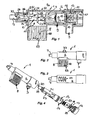
- the in the FIGS. 1 to 20 illustrated reflux barrier 1 has a cartridge receptacle 2, which can be integrated, for example, in a shape-adapted recess on the toilet seat.
- a cartridge receptacle 2 which can be integrated, for example, in a shape-adapted recess on the toilet seat.
- a connectable to an inlet 3 of the cartridge receptacle 2 jet nozzle 4 and a catching part 5 is provided, which has to catch the coming of the jet nozzle 4 via a free jet path 6 liquid jet.
- the jet nozzle 4 is connected via the inlet 3 of the cartridge holder 2 with the drinking water supply network, the catching part 5 is over a course of Cartridge receptacle 2 with a spray nozzle not shown or the in Fig.
- a spacer 68 is integrally formed, which has to ensure a standard minimum distance between the outlet 8 and a downstream in the flow direction backflow level.
- This spacer 68 is approximately sleeve-shaped in cross-section and has on its longitudinal sides on both sides through-flow openings 69, which are oriented in the longitudinal extension of the spacer 68.
- the in the FIGS. 1 to 8 shown backflow locks 1 is associated with an insertion cartridge 9, which carries the jet nozzle 4 and the catching part 5.
- This insertion cartridge 9 is inserted through an insertion opening 10, for example in the in FIG. 1 shown cartridge receptacle 2 can be used and releasably fixed therein, that the jet nozzle 4 is connected to the inlet 3 of the cartridge holder 2.
- the Einsetzkartuschen 9 arranged in its between jet nozzle 4 and 5 catching and the free jet path 6 forming or delimiting cartridge section has at least one associated with the outlet 8 of the cartridge receptacle 2 cartridge opening 11.
- the cartridge opening 11 and the outlet 8 of the cartridge receptacle 2 adjoin one another directly.
- the cap 12 is here releasably held by means of a plug / rotary connection to the cartridge receptacle 2, wherein the plug / rotary connection may be formed, for example, as a bayonet or the like Renktagen.
- the cap 12 has a cap extension 13, onto which the insertion cartridge 9 can be pushed or pushed with its adjacent, end-side open cartridge end region 14.
- the insertion cartridge 9 is thus easy to handle even in confined spaces on the always accessible from the outside cap 12.
- the insertion cartridge 9 has at least one inlet 15 which can be connected to the inlet 3 of the cartridge receptacle 2 via an annular space 16 which is enclosed between the inner circumference of the cartridge receptacle 2 and the outer periphery of the cartridge and circumferentially sealed on both sides in the longitudinal direction of the cartridge receptacle 2.
- the inlet cartridge 9 has here two oval and oriented in the cartridge circumferential direction inlets 15.
- the inlet 3 of the cartridge receptacle 2 opens in the circumferential direction evenly spaced from the arranged here on opposite sides at the same height inlets 15 in the annular space 16th
- FIGS. 1 and 5 From a comparison of FIGS. 1 and 5 on the one hand and the FIGS. 4 and 8th on the other hand, it can be seen that the cap extension 13 by a number of parallel, slightly spaced apart and lamellar to each other arranged flow guide walls 17 is formed. If the insertion cartridge 9 is placed on the cap 12, the spaces between the flow guide walls 17 connect the inlets 15 with each other, so that the water flows flowing in through the inlets 15 collide there and deflect in the longitudinal direction of the cartridge, where they pass through between the adjacent flow guide walls 17 in the direction of the jet nozzle 4 arranged free passages or openings 18 flow into the cartridge interior.
- an insertion cartridge 19 is provided, which can be inserted from the end face open cartridge end portion 14 in the cartridge interior.
- the insertion cartridge 19 has at least one backflow preventer, which allows a flow of water only in the direction of the jet nozzle 4.
- the Einsetzpatrone 19 also has a flow rate regulator, which has to limit the pressure per unit time flowing through water pressure-independent to a certain value and regulate.
- the jet nozzle 4 is guided in a sleeve-shaped jet nozzle receptacle 50 slidably.
- This jet nozzle receptacle 50 is integrally connected to the catching part 5 via at least one connecting web 51 and preferably two connecting webs 51 arranged parallel to the free blasting path 6.
- return flow restrictor 100 form the jet nozzle receptacle 50 and the associated capture part 5 an insertion element 52 which is insertable into a cup-shaped housing 53.
- the housing 53 has for this purpose a longitudinal insertion opening 54, through which the insertion element 52 can be used.
- the insertion element 52 is detachably fixable in the housing 53 such that the insertion opening 54 simultaneously forms the outlet 8.
- the jet nozzle receptacle 50 can be closed at its end facing away from the jet nozzle 4 by means of a cover 55 which carries an inlet connectable to the inlet.
- This inlet is formed here as a connection nipple 56 which is connectable via a hose not shown with the inlet.
- at least one spacer may be formed on the housing 53. Preferred is an embodiment, not shown here, in which a plurality of spacers are provided, which are arranged in particular in the housing corner regions.
- connection nipple 57 or the like outlet is also integrally formed on the catching part 5 in order to connect the catching part 5, for example via a hose line, to the outlet leading to a point of consumption.
- a groove 58 is provided on the outer peripheral side of the catching part 5 and on the connecting nipple 57 serving as an outlet, into which a wall opening 59 open towards the insertion opening 54 engages on the housing front side of the housing 53. Since the insertion opening defining the wall opening 59 engages in the groove 58, positionally correct positioning of the insertion element 52 formed by the jet nozzle 4 and the catching part 5 is always ensured.
- a guide wall 60 is integrally formed on the jet nozzle receptacle 50 on the outside.
- This guide wall 60 on both sides of each one the connecting webs 51 engages, is in the position of use of a fork-shaped holder 61, which protrudes in the housing interior of the housing 53.
- the forks 62 of the holder 61 are arranged on both sides at a distance from the nozzle opening of the jet nozzle 4 in order not to impair the proper functioning of the jet nozzle 4. Since the guide wall 60 bears against the holder 61 in the use position, a positionally correct insertion of the insertion element 52 into the housing 53 is likewise ensured. Since the holder 61 is arranged with their forks 62 between the connecting webs 51, a rotational securing of the insertion element 52 in the housing 53 is achieved.
- FIG. 21 is clearly visible that the jet nozzle receptacle 50 frontally occlusive cover 55 in the position of use rests on the inside of the adjacent housing end face of the housing 53.
- the connecting nipple 56 formed on the cover 55 passes through a holding opening 70, which is open towards the insertion opening 54, on the housing front side.
- the holding opening 70 and also the wall opening, which receive the connection nipples 56, 57 in the position of use have in their opening outline at least on one side and preferably on both sides a recess 71, by means of which the connection nipple 56 or 57 can be releasably latched.
- the recesses 71 provided on both sides in the opening outline give the holding opening 70 and also the wall opening 59 an opening outline which is comparable to the keyhole provided for a beard key. In this way, a secure hold of the insertion 52 in the housing 53 is ensured.
- the jet nozzle 4 of the return flow barriers 1, 100 has to convert the pressure energy of the water coming from the supply network into the kinetic energy of the water jet.
- the flow guide tapers in a funnel shape in the direction of the nozzle opening 21 of the jet nozzle 4.
- the jet nozzle 4 is designed as a nipple-shaped or knob-shaped projection 22 in order to minimize the effects on the water jet caused by the adhesion forces.
- the free beam path 6 is at a distance from the capture part 5 and jet nozzle 4 at least one spray or partition wall 23 is arranged, which has a passage opening 24 which has a larger compared to the beam cross section of the liquid jet clear cross-section.
- the clear opening cross-section of the passage opening 24 is dimensioned so that the liquid jet unbundled from the passage opening 24 and just passes through non-contact.
- the spray or dividing wall 23 provided at a distance between the blasting nozzle 4 and the catching part 5 is arranged closer to the catching part 5.
- the spray or partition wall 23 is spaced at least four millimeters from the catching part 5.
- the trapping part 5 is intended to convert the kinetic energy of the water jet coming from the jet nozzle 4 and the trapping part 5 into a corresponding pressure energy, which is subsequently applied to the cleaning or water jet emerging, for example, from the spray nozzle, the hand shower 45 of a sub-shower or another sanitary appliance is needed. From the FIGS. 1 . 5 . 21 and 26 It is clear that the catching part 5 widens in a funnel shape in its clear cross-section.
- the catching part 5 has a catching opening 28 which, at least in its inflow-side section 25, has a hollow-cylindrical clear opening cross-section. Subsequent to the hollow-cylindrical section 25, the catching part 5 widens in the direction of the outlet.
- the catching part 5 conically or in the clear cross section arcuately widening sections 26, 27, of which the inflow-side section 26 has a smaller compared to the subsequent section 27 expansion.
- the catching part 5 opens into a cartridge outlet 30 arranged at the front-side cartridge end 29, which is provided adjacent to the outlet 7 of the cartridge receptacle 2.
- the insertion cartridge 9 is circumferentially sealed in the region of the cartridge end 30 having cartridge end 29 relative to the circumference of the cartridge receptacle 2.
- the insertion cartridge 9 of the backflow barrier 1 can be used and fixed in the cartridge receptacle 2 such that the blasting nozzle 4 is connected to the inlet 3 of the cartridge receptacle 2 and at the same time the catching part 5 is connected to the outlet 7 of the cartridge receptacle 2.
- the insertion cartridge 9 of the return flow barrier 1 has at least one cartridge opening 11 in its cartridge section which is arranged between the jet nozzle 4 and the catching part 5 and delimits the free jet path 6 and which communicates with the outlet 8 of the cartridge receptacle 2.
- the cartridge recording 2 molded, for example, in a toilet seat, a toilet ceramics or a bathtub or - as here - can be designed as an insertable into a corresponding receptacle on the toilet seat, on the toilet ceramics or on the tub opening of a bathtub housing adapt little effort to a variety of predetermined conditions such that always an optimal function is guaranteed.
- the backflow barrier 1 is also easy to clean and to descale if necessary.
- FIGS. 1 to 4 . 5 to 8 and 21 to 27 illustrated embodiments of the backflow barrier 1, 100 differ only in that in the in FIGS. 5 to 8
- the jet nozzle 4 on the one hand and the catching part 5 on the other hand each configured as a releasably insertable into the insertion cartridge 9 component. Due to the design of jet nozzle 4 and trapping 5 as a separate component, the modular design of in FIGS. 5 to 8 shown backflow barrier 1 favors that optionally also by replacing the jet nozzle 4 and / or the catching part 5, the insertion cartridge 9 can be adapted to the respective conditions of the existing on-site supply network.
- the housing 53 of in FIG. 21 shown reflux barrier 100 two slot-shaped ventilation openings 63, which are arranged on the insertion opening 54 facing away from the longitudinal side. These two slot-shaped ventilation openings 63 are oriented parallel to one another and at a distance from each other in the housing longitudinal direction. Since the connecting webs 51 of the insertion element 52 located in the housing 53 project into a plane imagined by the slot-shaped ventilation openings 63, a labyrinth-like air guide through the ventilation openings 63 is also achieved in the return flow barrier 100.
- the backflow barriers 1, 100 shown here provide maximum safety in order to prevent backflow of contaminated water into an area connected to the drinking water supply network.
- Design of the return flow lock 1 facilitates the replacement of the insertion cartridge 9 against a corresponding connector 31. From a comparison of FIGS. 9 and 11 It is clear that the sleeve-shaped connecting piece 31 is placed with its open front end on the cap extension 13 of the cap 12 such that lateral inlet openings 32 are connected via the annular space 16 with the inlet 3 of the cartridge receptacle 2. In this case, the inserted into the connecting piece 31 Einsetzpatrone 19 between the cap extension 13 and a arranged on the inner circumference of the connecting piece 31 annular shoulder 33 is secured.
- FIGS. 12 to 15 and 21 to 27 At least the portion of a deviating designed return flow restrictor 1, 100 is the jet nozzle 4 having shown. Like from the FIGS. 12 to 15 and 21 to 27 can be seen, the jet nozzle 4 is guided displaceably in the jet nozzle receptacle 50 and of a in.
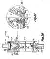
- this deviating designed return flow restrictor 1, 100 FIGS. 13 and 14 shown ready position under the pressure of the liquid flowing through against a restoring force in a spray position displaced in which injection position - like FIGS. 15 and 16 or 26 and 27 show - the jet nozzle 4 with its nozzle opening 21 forming and formed as a projection 22 nozzle portion pierces a provided in an elastic membrane 35 through opening 36. While at the in the FIGS.
- the restoring force is applied by a return spring 34 to the jet nozzle 4, forms in the in FIGS. 26 and 27 shown embodiment, the elastic material and / or the elastically flexible shape of the elastic membrane 35 acting on the spray nozzle 4 return element.
- FIGS. 26 and 27 it can be seen that the jet nozzle 4 to protrudes into the here cup-shaped membrane 35 which carries the insertion opening 36 at the pot bottom of their pot shape.
- the peripheral edge of the membrane 35 facing away from the bottom of the pot is supported elastically on the jet nozzle 4.
- the membrane 35 seals the jet nozzle receptacle 50 in the region of an opening provided in the guide wall 64 in the region of the pot bottom of their pot shape and that the membrane 35 at the periphery of its cup shape at least one flow opening and preferably a plurality of spaced apart flow openings 65 which slit-shaped and oriented in the circumferential direction.
- These flow openings 65 connect the interior 66 of the jet nozzle receptacle 50 with the interior 67 of the cup-shaped membrane 35, so that a fluid exchange between these interior spaces 66, 67 during the sliding movement of the jet nozzle 4 is made possible.
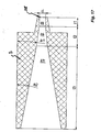
- FIG. 17 shows a backflow barrier according to the invention in a schematic partial longitudinal section in the region of their catching part 5.
- Aus FIG. 17 It is clear that the catching part 5 protrudes nipple-shaped or knob-shaped on the outer peripheral side in its section delimiting the catching opening 28. Furthermore, in FIG. 17 shown that the catching part 5 has a hollow cylindrical or approximately hollow cylindrical section in the region of its catching opening 28. It may be advantageous if the ratio of the length l 1 of this section in comparison to the clear inner diameter of the capture opening is preferably greater than / equal to 0.2 to less than / equal to 10, in particular greater than / equal to 1.5 to less than / equal to 2.6 , In FIG.
- the catching part 5 preferably expanded in a funnel shape following the hollow cylindrical part. It is provided that the catching part on the outflow side of its hollow cylindrical portion 25 has at least one in the flow direction conically widening portion 26, 27 and that the immediately adjacent to the hollow cylindrical portion section has a length l 2 from 0 to 100 mm inclusive, preferably from 0 to 30 mm inclusive. In this case, the embodiment shown here is preferred in which the catching part 5 has at least two sections 26, 27 which flare in the direction of flow, wherein at least two downstream sections 26, 27 have the length l 3 of at least the downstream and preferably more extensive section 0 to 100 mm, preferably from 0 to 30 mm.
- the catching part 5 has an angle a 2 of greater than / equal to 0 to less than / equal to 45 °, preferably greater than / equal to 0 to less than / equal to 18 °, in the region of its more conically widening section 27 with respect to the longitudinal axis of the catching part , In this case, between this more conically widening portion 27 and the hollow cylindrical portion 25 provided portion of the catching part 5, which has a lower conicity, an angle a 1 relative to the catching longitudinal axis of greater than or equal to 0 to / equal to 45 °, preferably from greater than or equal to 0 to less than or equal to 13 °.
- the backflow barrier 1 shown here can be connected upstream of a shower and, in particular, the sub-shower assigned to a toilet seat on the inflow side. In addition, however, it is also possible for the return flow lock 1 upstream of the water inlet of a bath 38 on the inflow side. From the schematic representation in FIG. 18 It is clear that in the bath 38 shown here, the bathtub inlet 39 and the bath spout 40 is provided separately from each other on the tub bottom of the bath 38. But it is also possible to merge the bathtub inlet 39 and the bath spout 40 in a common trough opening. As well as the bath inlet 39 is arranged in any case below the water surface of the bathwater located in the bath 38, the bath water can splash-free and quietly enter the bathtub 38. However, since the water pressing on the incoming water and the bathtub inlet 39 also carries the risk that contaminated bathing water or service water flows into the water supply network, in the case of FIG. 18 shown application example to ensure an effective inlet protection necessarily.
- the water inlet into the bath 38 is operated via a manually operable outlet fitting 41, which combines a hot water inlet 42 and a cold water inlet 43 in it. After coming from the outlet fitting 41 water the Return flow barrier 1 has reached, the water flowing through can pass between a return flow barrier 1 and the bath inlet 39 interposed backflow preventer 44 before the water flows in the bathtub inlet 39 on the bottom side in the bath 38.
- the backflow barrier 1 according to the invention can also be interposed in the example leading to a hand shower 45 water inlet 49 of a schematically indicated below shower, which sub-shower in the toilet ceramic or in the toilet seat, where appropriate, also installed later.
- the jet nozzle 4 is in the FIGS. 21 to 27 shown backlash 100 in the jet nozzle receptacle 50 slidably guided.
- the jet nozzle receptacle 50 is designed for this purpose on its side facing away from the nozzle opening 21 by means of the lid 55 apparently.
- the jet nozzle 4 can be inserted into the interior of the jet nozzle receptacle 50.
- FIGS. 21 to 27 shown backlash 100 in the jet nozzle receptacle 50 slidably guided.
- the jet nozzle receptacle 50 is designed for this purpose on its side facing away from the nozzle opening 21 by means of the lid 55 apparently.
- the jet nozzle 4 By closed in the position of use by means of the lid 55 insertion opening of the jet nozzle receptacle 50, the jet nozzle 4 can be inserted into the interior of the jet nozzle receptacle 50.
- FIGS. 21 to 27 shown backlash 100 in the jet nozzle receptacle 50 slidably guided.
- the jet nozzle 4 in the backflow barrier 100 is displaceable from the ready position shown left to the longitudinal axis under the pressure of the liquid flowing through against a restoring force in the right shown spray position, in which injection position the jet nozzle 4 with its nozzle opening 21 forming Nozzle section pierces the opening provided in the elastic membrane 35 through opening 36.
- the here substantially conical jet nozzle 4 here has an approximately centrally disposed annular shoulder on which the cap-shaped membrane 35 is supported.
- the membrane 35 which here cup-shaped and made of elastic material is shaped so that it exerts the restoring force on the slidably guided jet nozzle 4.
- the sliding path of the jet nozzle 4 in the jet nozzle receptacle 50 is limited on the one hand by a screen 20 upstream of the jet nozzle 4 and on the other hand by an annular shoulder 47 on the inner periphery of the jet nozzle receptacle 50.
- FIGS. 28 to 30 the jet nozzle 4 of the reflux barrier 1 shown in FIGS. 21 to 27 is depicted.
- the jet nozzle 4 in the region of its nozzle opening 21 on an annular shoulder.
- an annular projection 22 is integrally formed, which surrounds the nozzle opening 21.
- the nozzle opening of the jet nozzle 4 bounding opening edge is sharp-edged and designed to chamfer and rounding.
- the opening edge of the nozzle opening 21 has an edge degree smaller than 0.1 mm or greater minus 0.1 mm.
- the sharp-edged opening edge forms an inner peripheral side provided tear-off edge, which favors a sharply shaped in the jet nozzle 4 and non-splashing liquid jet.
Landscapes
- Health & Medical Sciences (AREA)
- Public Health (AREA)
- Life Sciences & Earth Sciences (AREA)
- Engineering & Computer Science (AREA)
- Hydrology & Water Resources (AREA)
- Water Supply & Treatment (AREA)
- Molecular Biology (AREA)
- Epidemiology (AREA)
- Nozzles (AREA)
- Devices For Medical Bathing And Washing (AREA)
- Bathtubs, Showers, And Their Attachments (AREA)
- Domestic Plumbing Installations (AREA)
Applications Claiming Priority (2)
| Application Number | Priority Date | Filing Date | Title |
|---|---|---|---|
| DE202012002585U DE202012002585U1 (de) | 2012-03-13 | 2012-03-13 | Rückfluss-Sperre für eine Unterdusche |
| EP13713350.0A EP2825707B1 (fr) | 2012-03-13 | 2013-03-05 | Dispositif anti-refoulement pour une douchette |
Related Parent Applications (2)
| Application Number | Title | Priority Date | Filing Date |
|---|---|---|---|
| EP13713350.0A Division EP2825707B1 (fr) | 2012-03-13 | 2013-03-05 | Dispositif anti-refoulement pour une douchette |
| EP13713350.0A Division-Into EP2825707B1 (fr) | 2012-03-13 | 2013-03-05 | Dispositif anti-refoulement pour une douchette |
Publications (2)
| Publication Number | Publication Date |
|---|---|
| EP2918741A1 true EP2918741A1 (fr) | 2015-09-16 |
| EP2918741B1 EP2918741B1 (fr) | 2017-08-09 |
Family
ID=48044714
Family Applications (4)
| Application Number | Title | Priority Date | Filing Date |
|---|---|---|---|
| EP15002208.5A Active EP2980327B1 (fr) | 2012-03-13 | 2013-03-05 | Dispositif anti-retour pour une douche anale |
| EP15000357.2A Active EP2918741B1 (fr) | 2012-03-13 | 2013-03-05 | Blocage de refoulement |
| EP13713350.0A Active EP2825707B1 (fr) | 2012-03-13 | 2013-03-05 | Dispositif anti-refoulement pour une douchette |
| EP18154708.4A Active EP3358094B1 (fr) | 2012-03-13 | 2013-03-05 | Clapet anti-retour |
Family Applications Before (1)
| Application Number | Title | Priority Date | Filing Date |
|---|---|---|---|
| EP15002208.5A Active EP2980327B1 (fr) | 2012-03-13 | 2013-03-05 | Dispositif anti-retour pour une douche anale |
Family Applications After (2)
| Application Number | Title | Priority Date | Filing Date |
|---|---|---|---|
| EP13713350.0A Active EP2825707B1 (fr) | 2012-03-13 | 2013-03-05 | Dispositif anti-refoulement pour une douchette |
| EP18154708.4A Active EP3358094B1 (fr) | 2012-03-13 | 2013-03-05 | Clapet anti-retour |
Country Status (7)
| Country | Link |
|---|---|
| US (1) | US9909294B2 (fr) |
| EP (4) | EP2980327B1 (fr) |
| BR (1) | BR112014022363B1 (fr) |
| DE (2) | DE202012002585U1 (fr) |
| ES (4) | ES2640632T3 (fr) |
| TR (2) | TR201802812T4 (fr) |
| WO (1) | WO2013135350A1 (fr) |
Families Citing this family (12)
| Publication number | Priority date | Publication date | Assignee | Title |
|---|---|---|---|---|
| JP6596943B2 (ja) * | 2015-06-05 | 2019-10-30 | Toto株式会社 | 衛生洗浄装置 |
| CN107165238A (zh) * | 2016-03-08 | 2017-09-15 | 慈溪三和智能卫浴有限公司 | 一种温水便座水箱手动放水阀及温水便座装置 |
| DE102017102115A1 (de) | 2017-02-03 | 2018-08-09 | Ulrich Stark-Gariglio | Toilette |
| DE202017102237U1 (de) | 2017-04-13 | 2018-07-16 | Neoperl Gmbh | WC-Spülkasten und korrespondierende Verwendung eines Injektors |
| DE102017108028A1 (de) * | 2017-04-13 | 2018-10-18 | Neoperl Gmbh | WC-Spülkasten und korrespondierende Verwendung eines Injektors |
| CN111051624B (zh) * | 2017-11-15 | 2021-12-31 | 松下知识产权经营株式会社 | 水洗便器 |
| EP3768903A4 (fr) * | 2018-03-21 | 2022-05-04 | Eczacibasi Yapi Gerecleri Sanayi Ve Ticaret Anonim Sirketi | Système d'installation d'un mécanisme de bidet |
| US12239588B2 (en) * | 2020-04-13 | 2025-03-04 | Neville Cameron | Commode wheelchair |
| TR202019956A2 (tr) * | 2020-12-07 | 2021-04-21 | Iz Yapi Malzeme Ve Ekipmanlari Sanayi Ve Ticaret Anonim Sirketi | Klozetlerde kullanılmak üzere geliştirilmiş bir geri akış düzeneği. |
| DE102022102232A1 (de) | 2022-01-31 | 2023-08-03 | Grohe Ag | Funktionseinheit für ein Dusch-WC sowie Dusch-WC mit einer Funktionseinheit |
| DE202022103854U1 (de) | 2022-07-08 | 2023-10-18 | Neoperl Ag | WC-Sitz-Ring |
| DE202025101023U1 (de) | 2025-02-26 | 2026-06-03 | Carsten Willers Consulting Gmbh | Toilette mit Bidetfunktion |
Citations (4)
| Publication number | Priority date | Publication date | Assignee | Title |
|---|---|---|---|---|
| CH444076A (de) | 1965-04-14 | 1967-09-15 | Susten Anstalt | Vorrichtung zum Verhindern des Rücksaugens von Flüssigkeit aus einem von einem Speisenetz unter Druck gespeisten Behälter in das Speisenetz |
| DE2417731A1 (de) * | 1974-04-11 | 1975-10-30 | Aweco App & Geraetebau Kg | Vorrichtung zur rueckflussverhinderung, insbesondere fuer wasserenthaertungseinrichtungen |
| DE2818691A1 (de) * | 1978-04-28 | 1979-10-31 | Walter Holzer | Ruecksaugsperre, insbesondere fuer hausgeraete |
| DE3708169A1 (de) * | 1987-03-13 | 1988-09-22 | Licentia Gmbh | Rueckflussverhinderer |
Family Cites Families (13)
| Publication number | Priority date | Publication date | Assignee | Title |
|---|---|---|---|---|
| US2071044A (en) | 1934-03-03 | 1937-02-16 | Western Electric Co | Method and apparatus for motion picture visual accompaniments to musical scores |
| US2071004A (en) * | 1936-03-23 | 1937-02-16 | William C Shanley | Vacuum breaker for flush valve devices |
| GB1166040A (en) * | 1965-12-22 | 1969-10-01 | Zanussi A Spa Industrie | Liquid Pollution Preventing Devices |
| DE1784274A1 (de) * | 1968-07-24 | 1972-06-08 | Licentia Gmbh | Ruecksaugschutzvorrichtung,insbesondere fuer Wasch- und Geschirrspuelmaschinen |
| DE2417732C2 (de) * | 1974-04-11 | 1977-02-24 | Aweco App & Geraetebau Kg | Vorrichtung zum Verhindern des Zurückfliessens von Flüssigkeit aus einer Wasserverbrauchseinrichtung in das Wasserversorgungssystem |
| US4592382A (en) * | 1984-08-27 | 1986-06-03 | Aqua-Giene, Inc. | Anti-siphon nozzle |
| DE9218982U1 (de) * | 1991-07-18 | 1996-10-17 | Hydro Systems Co., Cincinnati, Ohio | Chemikalienejektor mit integriertem länglichen Luftspalt |
| DE9113239U1 (de) * | 1991-10-24 | 1992-01-16 | Metallwerke Gebr. Seppelfricke Gmbh & Co, 4650 Gelsenkirchen | Unterputz-Rohrunterbrecher |
| US5518020A (en) * | 1994-06-14 | 1996-05-21 | Dema Engineering Co. | Proportioner |
| US5678592A (en) | 1996-01-16 | 1997-10-21 | S. C. Johnson & Son, Inc. | Back flow prevention device |
| DE10308838A1 (de) * | 2003-02-27 | 2004-09-09 | Hans Sasserath & Co. Kg | Ventilanordnung für einen Rohrtrenner |
| PL359448A1 (en) | 2002-04-03 | 2003-10-06 | Hans Sasserath & Co Kg | Set of isolating valves for water supply system |
| CA2767337C (fr) * | 2008-07-21 | 2014-04-08 | Jules Allard | Bidet escamotable |
-
2012
- 2012-03-13 DE DE202012002585U patent/DE202012002585U1/de not_active Expired - Lifetime
-
2013
- 2013-03-05 ES ES15000357.2T patent/ES2640632T3/es active Active
- 2013-03-05 ES ES15002208.5T patent/ES2659074T3/es active Active
- 2013-03-05 EP EP15002208.5A patent/EP2980327B1/fr active Active
- 2013-03-05 US US14/385,045 patent/US9909294B2/en not_active Expired - Fee Related
- 2013-03-05 EP EP15000357.2A patent/EP2918741B1/fr active Active
- 2013-03-05 EP EP13713350.0A patent/EP2825707B1/fr active Active
- 2013-03-05 TR TR2018/02812T patent/TR201802812T4/tr unknown
- 2013-03-05 WO PCT/EP2013/000630 patent/WO2013135350A1/fr not_active Ceased
- 2013-03-05 ES ES18154708T patent/ES2786629T3/es active Active
- 2013-03-05 DE DE102013003629A patent/DE102013003629A1/de not_active Withdrawn
- 2013-03-05 BR BR112014022363-7A patent/BR112014022363B1/pt not_active IP Right Cessation
- 2013-03-05 TR TR2018/15302T patent/TR201815302T4/tr unknown
- 2013-03-05 EP EP18154708.4A patent/EP3358094B1/fr active Active
- 2013-03-05 ES ES13713350.0T patent/ES2691964T3/es active Active
Patent Citations (4)
| Publication number | Priority date | Publication date | Assignee | Title |
|---|---|---|---|---|
| CH444076A (de) | 1965-04-14 | 1967-09-15 | Susten Anstalt | Vorrichtung zum Verhindern des Rücksaugens von Flüssigkeit aus einem von einem Speisenetz unter Druck gespeisten Behälter in das Speisenetz |
| DE2417731A1 (de) * | 1974-04-11 | 1975-10-30 | Aweco App & Geraetebau Kg | Vorrichtung zur rueckflussverhinderung, insbesondere fuer wasserenthaertungseinrichtungen |
| DE2818691A1 (de) * | 1978-04-28 | 1979-10-31 | Walter Holzer | Ruecksaugsperre, insbesondere fuer hausgeraete |
| DE3708169A1 (de) * | 1987-03-13 | 1988-09-22 | Licentia Gmbh | Rueckflussverhinderer |
Also Published As
| Publication number | Publication date |
|---|---|
| TR201815302T4 (tr) | 2018-11-21 |
| EP3358094A1 (fr) | 2018-08-08 |
| EP2980327A1 (fr) | 2016-02-03 |
| EP3358094B1 (fr) | 2020-01-29 |
| DE102013003629A1 (de) | 2013-09-19 |
| EP2980327B1 (fr) | 2018-01-03 |
| WO2013135350A8 (fr) | 2014-12-04 |
| ES2640632T3 (es) | 2017-11-03 |
| TR201802812T4 (tr) | 2018-03-21 |
| US9909294B2 (en) | 2018-03-06 |
| US20150033464A1 (en) | 2015-02-05 |
| EP2825707B1 (fr) | 2018-08-15 |
| ES2786629T3 (es) | 2020-10-13 |
| ES2691964T3 (es) | 2018-11-29 |
| BR112014022363B1 (pt) | 2021-01-19 |
| DE202012002585U1 (de) | 2013-06-17 |
| ES2659074T3 (es) | 2018-03-13 |
| WO2013135350A1 (fr) | 2013-09-19 |
| EP2918741B1 (fr) | 2017-08-09 |
| EP2825707A1 (fr) | 2015-01-21 |
Similar Documents
| Publication | Publication Date | Title |
|---|---|---|
| EP2980327B1 (fr) | Dispositif anti-retour pour une douche anale | |
| EP2089581B1 (fr) | Régulateur de jet | |
| EP1853771B1 (fr) | Unite fonctionnelle sanitaire | |
| EP2986787B1 (fr) | Wc muni d'une douchette intime intégrée dans le distributeur d'eau de rinçage | |
| EP4050168B1 (fr) | Accessoire pour toilettes pourvu de dispositif de douche | |
| EP2167237B1 (fr) | Évacuation d'eau pour une installation sanitaire basse pression | |
| EP1789636B1 (fr) | Unite d'ecoulement sanitaire | |
| EP3447201B1 (fr) | Armature sanitaire pourvu d'un mécanisme d'insertion | |
| DE4039329C2 (de) | Brausekopf | |
| DE202013002055U1 (de) | Rückfluss-Sperre für eine Unterdusche | |
| EP0818585B1 (fr) | Dispositif de raccordement mural | |
| EP1020571A2 (fr) | Article sanitaire, en particulier une pomme de douche, avec un dispositif de commutation pour influencer un débit de fluide | |
| EP2708664B1 (fr) | Armature d'écoulement comprenant un corps d'écoulement ayant la forme d'une carafe | |
| CN203361295U (zh) | 用于坐浴器的回流截止器 | |
| EP0441151A1 (fr) | Robinet avec protection contre le reflux d'eau | |
| DE102016201342B4 (de) | Vorrichtung und Dampflanze zum Aufschäumen und/oder Erwärmen von Milch | |
| EP1761732B1 (fr) | Purgeur d'air | |
| EP3992377A1 (fr) | Insert de régulateur de jet avec protection contre la recontamination | |
| EP3327208B1 (fr) | Unité d'écoulement sanitaire | |
| EP1390586B1 (fr) | Bloc de robinetterie sanitaire | |
| DE10258832A1 (de) | Ventil | |
| EP4283057B1 (fr) | Distributeur d'eau de rinçage | |
| DE19515959A1 (de) | Absicherung gegen Rücksaugen einer Badewannen-Ein- und Überlauf-Garnitur | |
| DE8505923U1 (de) | Einlaufvorrichtung an der abflussleitung einer dialysestation | |
| DE4005060A1 (de) | Automatische rueckfuehrungsvorrichtung fuer die luftkammer von hydropneumatischen spueleinrichtungen fuer toiletten-spuelkaesten |
Legal Events
| Date | Code | Title | Description |
|---|---|---|---|
| PUAI | Public reference made under article 153(3) epc to a published international application that has entered the european phase |
Free format text: ORIGINAL CODE: 0009012 |
|
| AC | Divisional application: reference to earlier application |
Ref document number: 2825707 Country of ref document: EP Kind code of ref document: P |
|
| AK | Designated contracting states |
Kind code of ref document: A1 Designated state(s): AL AT BE BG CH CY CZ DE DK EE ES FI FR GB GR HR HU IE IS IT LI LT LU LV MC MK MT NL NO PL PT RO RS SE SI SK SM TR |
|
| AX | Request for extension of the european patent |
Extension state: BA ME |
|
| 17P | Request for examination filed |
Effective date: 20160316 |
|
| RBV | Designated contracting states (corrected) |
Designated state(s): AL AT BE BG CH CY CZ DE DK EE ES FI FR GB GR HR HU IE IS IT LI LT LU LV MC MK MT NL NO PL PT RO RS SE SI SK SM TR |
|
| GRAP | Despatch of communication of intention to grant a patent |
Free format text: ORIGINAL CODE: EPIDOSNIGR1 |
|
| INTG | Intention to grant announced |
Effective date: 20170420 |
|
| GRAS | Grant fee paid |
Free format text: ORIGINAL CODE: EPIDOSNIGR3 |
|
| GRAA | (expected) grant |
Free format text: ORIGINAL CODE: 0009210 |
|
| AC | Divisional application: reference to earlier application |
Ref document number: 2825707 Country of ref document: EP Kind code of ref document: P |
|
| AK | Designated contracting states |
Kind code of ref document: B1 Designated state(s): AL AT BE BG CH CY CZ DE DK EE ES FI FR GB GR HR HU IE IS IT LI LT LU LV MC MK MT NL NO PL PT RO RS SE SI SK SM TR |
|
| REG | Reference to a national code |
Ref country code: GB Ref legal event code: FG4D Free format text: NOT ENGLISH |
|
| REG | Reference to a national code |
Ref country code: CH Ref legal event code: EP Ref country code: AT Ref legal event code: REF Ref document number: 917004 Country of ref document: AT Kind code of ref document: T Effective date: 20170815 |
|
| REG | Reference to a national code |
Ref country code: IE Ref legal event code: FG4D Free format text: LANGUAGE OF EP DOCUMENT: GERMAN |
|
| REG | Reference to a national code |
Ref country code: CH Ref legal event code: NV Representative=s name: GACHNANG AG PATENTANWAELTE, CH |
|
| REG | Reference to a national code |
Ref country code: DE Ref legal event code: R096 Ref document number: 502013008054 Country of ref document: DE |
|
| REG | Reference to a national code |
Ref country code: ES Ref legal event code: FG2A Ref document number: 2640632 Country of ref document: ES Kind code of ref document: T3 Effective date: 20171103 |
|
| REG | Reference to a national code |
Ref country code: NL Ref legal event code: MP Effective date: 20170809 |
|
| REG | Reference to a national code |
Ref country code: LT Ref legal event code: MG4D |
|
| PG25 | Lapsed in a contracting state [announced via postgrant information from national office to epo] |
Ref country code: LT Free format text: LAPSE BECAUSE OF FAILURE TO SUBMIT A TRANSLATION OF THE DESCRIPTION OR TO PAY THE FEE WITHIN THE PRESCRIBED TIME-LIMIT Effective date: 20170809 Ref country code: SE Free format text: LAPSE BECAUSE OF FAILURE TO SUBMIT A TRANSLATION OF THE DESCRIPTION OR TO PAY THE FEE WITHIN THE PRESCRIBED TIME-LIMIT Effective date: 20170809 Ref country code: NL Free format text: LAPSE BECAUSE OF FAILURE TO SUBMIT A TRANSLATION OF THE DESCRIPTION OR TO PAY THE FEE WITHIN THE PRESCRIBED TIME-LIMIT Effective date: 20170809 Ref country code: HR Free format text: LAPSE BECAUSE OF FAILURE TO SUBMIT A TRANSLATION OF THE DESCRIPTION OR TO PAY THE FEE WITHIN THE PRESCRIBED TIME-LIMIT Effective date: 20170809 Ref country code: NO Free format text: LAPSE BECAUSE OF FAILURE TO SUBMIT A TRANSLATION OF THE DESCRIPTION OR TO PAY THE FEE WITHIN THE PRESCRIBED TIME-LIMIT Effective date: 20171109 |
|
| PG25 | Lapsed in a contracting state [announced via postgrant information from national office to epo] |
Ref country code: LV Free format text: LAPSE BECAUSE OF FAILURE TO SUBMIT A TRANSLATION OF THE DESCRIPTION OR TO PAY THE FEE WITHIN THE PRESCRIBED TIME-LIMIT Effective date: 20170809 Ref country code: IS Free format text: LAPSE BECAUSE OF FAILURE TO SUBMIT A TRANSLATION OF THE DESCRIPTION OR TO PAY THE FEE WITHIN THE PRESCRIBED TIME-LIMIT Effective date: 20171209 Ref country code: RS Free format text: LAPSE BECAUSE OF FAILURE TO SUBMIT A TRANSLATION OF THE DESCRIPTION OR TO PAY THE FEE WITHIN THE PRESCRIBED TIME-LIMIT Effective date: 20170809 Ref country code: GR Free format text: LAPSE BECAUSE OF FAILURE TO SUBMIT A TRANSLATION OF THE DESCRIPTION OR TO PAY THE FEE WITHIN THE PRESCRIBED TIME-LIMIT Effective date: 20171110 Ref country code: BG Free format text: LAPSE BECAUSE OF FAILURE TO SUBMIT A TRANSLATION OF THE DESCRIPTION OR TO PAY THE FEE WITHIN THE PRESCRIBED TIME-LIMIT Effective date: 20171109 Ref country code: PL Free format text: LAPSE BECAUSE OF FAILURE TO SUBMIT A TRANSLATION OF THE DESCRIPTION OR TO PAY THE FEE WITHIN THE PRESCRIBED TIME-LIMIT Effective date: 20170809 |
|
| REG | Reference to a national code |
Ref country code: FR Ref legal event code: PLFP Year of fee payment: 6 |
|
| PG25 | Lapsed in a contracting state [announced via postgrant information from national office to epo] |
Ref country code: RO Free format text: LAPSE BECAUSE OF FAILURE TO SUBMIT A TRANSLATION OF THE DESCRIPTION OR TO PAY THE FEE WITHIN THE PRESCRIBED TIME-LIMIT Effective date: 20170809 Ref country code: DK Free format text: LAPSE BECAUSE OF FAILURE TO SUBMIT A TRANSLATION OF THE DESCRIPTION OR TO PAY THE FEE WITHIN THE PRESCRIBED TIME-LIMIT Effective date: 20170809 Ref country code: CZ Free format text: LAPSE BECAUSE OF FAILURE TO SUBMIT A TRANSLATION OF THE DESCRIPTION OR TO PAY THE FEE WITHIN THE PRESCRIBED TIME-LIMIT Effective date: 20170809 |
|
| REG | Reference to a national code |
Ref country code: DE Ref legal event code: R097 Ref document number: 502013008054 Country of ref document: DE |
|
| PG25 | Lapsed in a contracting state [announced via postgrant information from national office to epo] |
Ref country code: SK Free format text: LAPSE BECAUSE OF FAILURE TO SUBMIT A TRANSLATION OF THE DESCRIPTION OR TO PAY THE FEE WITHIN THE PRESCRIBED TIME-LIMIT Effective date: 20170809 Ref country code: EE Free format text: LAPSE BECAUSE OF FAILURE TO SUBMIT A TRANSLATION OF THE DESCRIPTION OR TO PAY THE FEE WITHIN THE PRESCRIBED TIME-LIMIT Effective date: 20170809 Ref country code: SM Free format text: LAPSE BECAUSE OF FAILURE TO SUBMIT A TRANSLATION OF THE DESCRIPTION OR TO PAY THE FEE WITHIN THE PRESCRIBED TIME-LIMIT Effective date: 20170809 |
|
| PLBE | No opposition filed within time limit |
Free format text: ORIGINAL CODE: 0009261 |
|
| STAA | Information on the status of an ep patent application or granted ep patent |
Free format text: STATUS: NO OPPOSITION FILED WITHIN TIME LIMIT |
|
| 26N | No opposition filed |
Effective date: 20180511 |
|
| PG25 | Lapsed in a contracting state [announced via postgrant information from national office to epo] |
Ref country code: SI Free format text: LAPSE BECAUSE OF FAILURE TO SUBMIT A TRANSLATION OF THE DESCRIPTION OR TO PAY THE FEE WITHIN THE PRESCRIBED TIME-LIMIT Effective date: 20170809 |
|
| PG25 | Lapsed in a contracting state [announced via postgrant information from national office to epo] |
Ref country code: MT Free format text: LAPSE BECAUSE OF FAILURE TO SUBMIT A TRANSLATION OF THE DESCRIPTION OR TO PAY THE FEE WITHIN THE PRESCRIBED TIME-LIMIT Effective date: 20170809 |
|
| PG25 | Lapsed in a contracting state [announced via postgrant information from national office to epo] |
Ref country code: MC Free format text: LAPSE BECAUSE OF FAILURE TO SUBMIT A TRANSLATION OF THE DESCRIPTION OR TO PAY THE FEE WITHIN THE PRESCRIBED TIME-LIMIT Effective date: 20170809 |
|
| REG | Reference to a national code |
Ref country code: BE Ref legal event code: MM Effective date: 20180331 |
|
| REG | Reference to a national code |
Ref country code: IE Ref legal event code: MM4A |
|
| PG25 | Lapsed in a contracting state [announced via postgrant information from national office to epo] |
Ref country code: LU Free format text: LAPSE BECAUSE OF NON-PAYMENT OF DUE FEES Effective date: 20180305 |
|
| PG25 | Lapsed in a contracting state [announced via postgrant information from national office to epo] |
Ref country code: IE Free format text: LAPSE BECAUSE OF NON-PAYMENT OF DUE FEES Effective date: 20180305 |
|
| PG25 | Lapsed in a contracting state [announced via postgrant information from national office to epo] |
Ref country code: BE Free format text: LAPSE BECAUSE OF NON-PAYMENT OF DUE FEES Effective date: 20180331 |
|
| PG25 | Lapsed in a contracting state [announced via postgrant information from national office to epo] |
Ref country code: PT Free format text: LAPSE BECAUSE OF FAILURE TO SUBMIT A TRANSLATION OF THE DESCRIPTION OR TO PAY THE FEE WITHIN THE PRESCRIBED TIME-LIMIT Effective date: 20170809 |
|
| PG25 | Lapsed in a contracting state [announced via postgrant information from national office to epo] |
Ref country code: CY Free format text: LAPSE BECAUSE OF FAILURE TO SUBMIT A TRANSLATION OF THE DESCRIPTION OR TO PAY THE FEE WITHIN THE PRESCRIBED TIME-LIMIT Effective date: 20170809 Ref country code: HU Free format text: LAPSE BECAUSE OF FAILURE TO SUBMIT A TRANSLATION OF THE DESCRIPTION OR TO PAY THE FEE WITHIN THE PRESCRIBED TIME-LIMIT; INVALID AB INITIO Effective date: 20130305 Ref country code: MK Free format text: LAPSE BECAUSE OF NON-PAYMENT OF DUE FEES Effective date: 20170809 |
|
| PG25 | Lapsed in a contracting state [announced via postgrant information from national office to epo] |
Ref country code: AL Free format text: LAPSE BECAUSE OF FAILURE TO SUBMIT A TRANSLATION OF THE DESCRIPTION OR TO PAY THE FEE WITHIN THE PRESCRIBED TIME-LIMIT Effective date: 20170809 |
|
| PGFP | Annual fee paid to national office [announced via postgrant information from national office to epo] |
Ref country code: FI Payment date: 20240319 Year of fee payment: 12 Ref country code: GB Payment date: 20240322 Year of fee payment: 12 |
|
| REG | Reference to a national code |
Ref country code: CH Ref legal event code: PK Free format text: BERICHTIGUNGEN |
|
| PGFP | Annual fee paid to national office [announced via postgrant information from national office to epo] |
Ref country code: TR Payment date: 20240223 Year of fee payment: 12 |
|
| PGFP | Annual fee paid to national office [announced via postgrant information from national office to epo] |
Ref country code: ES Payment date: 20240417 Year of fee payment: 12 |
|
| PGFP | Annual fee paid to national office [announced via postgrant information from national office to epo] |
Ref country code: AT Payment date: 20250319 Year of fee payment: 13 |
|
| PGFP | Annual fee paid to national office [announced via postgrant information from national office to epo] |
Ref country code: FR Payment date: 20250324 Year of fee payment: 13 |
|
| PGFP | Annual fee paid to national office [announced via postgrant information from national office to epo] |
Ref country code: DE Payment date: 20250513 Year of fee payment: 13 |
|
| PGFP | Annual fee paid to national office [announced via postgrant information from national office to epo] |
Ref country code: IT Payment date: 20250331 Year of fee payment: 13 |
|
| PGFP | Annual fee paid to national office [announced via postgrant information from national office to epo] |
Ref country code: CH Payment date: 20250401 Year of fee payment: 13 |
|
| PG25 | Lapsed in a contracting state [announced via postgrant information from national office to epo] |
Ref country code: FI Free format text: LAPSE BECAUSE OF NON-PAYMENT OF DUE FEES Effective date: 20250305 |
|
| GBPC | Gb: european patent ceased through non-payment of renewal fee |
Effective date: 20250305 |
|
| PG25 | Lapsed in a contracting state [announced via postgrant information from national office to epo] |
Ref country code: GB Free format text: LAPSE BECAUSE OF NON-PAYMENT OF DUE FEES Effective date: 20250305 |
|
| REG | Reference to a national code |
Ref country code: ES Ref legal event code: FD2A Effective date: 20260427 |
|
| PG25 | Lapsed in a contracting state [announced via postgrant information from national office to epo] |
Ref country code: TR Free format text: LAPSE BECAUSE OF NON-PAYMENT OF DUE FEES Effective date: 20250305 |
|
| PG25 | Lapsed in a contracting state [announced via postgrant information from national office to epo] |
Ref country code: ES Free format text: LAPSE BECAUSE OF NON-PAYMENT OF DUE FEES Effective date: 20250306 |