EP2918907A1 - Dispositif de fixation d'une lampe - Google Patents
Dispositif de fixation d'une lampe Download PDFInfo
- Publication number
- EP2918907A1 EP2918907A1 EP14159689.0A EP14159689A EP2918907A1 EP 2918907 A1 EP2918907 A1 EP 2918907A1 EP 14159689 A EP14159689 A EP 14159689A EP 2918907 A1 EP2918907 A1 EP 2918907A1
- Authority
- EP
- European Patent Office
- Prior art keywords
- fastening device
- lamp
- support arm
- deformation
- support
- Prior art date
- Legal status (The legal status is an assumption and is not a legal conclusion. Google has not performed a legal analysis and makes no representation as to the accuracy of the status listed.)
- Withdrawn
Links
- 230000005489 elastic deformation Effects 0.000 description 7
- 230000007704 transition Effects 0.000 description 6
- 238000003780 insertion Methods 0.000 description 3
- 230000037431 insertion Effects 0.000 description 3
- 238000009434 installation Methods 0.000 description 2
- 230000003014 reinforcing effect Effects 0.000 description 2
- 230000001154 acute effect Effects 0.000 description 1
- 238000005452 bending Methods 0.000 description 1
- 238000005352 clarification Methods 0.000 description 1
- 230000001419 dependent effect Effects 0.000 description 1
- 230000000694 effects Effects 0.000 description 1
- 238000004519 manufacturing process Methods 0.000 description 1
- 238000000465 moulding Methods 0.000 description 1
- 230000000007 visual effect Effects 0.000 description 1
Images



Classifications
-
- F—MECHANICAL ENGINEERING; LIGHTING; HEATING; WEAPONS; BLASTING
- F21—LIGHTING
- F21V—FUNCTIONAL FEATURES OR DETAILS OF LIGHTING DEVICES OR SYSTEMS THEREOF; STRUCTURAL COMBINATIONS OF LIGHTING DEVICES WITH OTHER ARTICLES, NOT OTHERWISE PROVIDED FOR
- F21V19/00—Fastening of light sources or lamp holders
- F21V19/0075—Fastening of light sources or lamp holders of tubular light sources, e.g. ring-shaped fluorescent light sources
- F21V19/008—Fastening of light sources or lamp holders of tubular light sources, e.g. ring-shaped fluorescent light sources of straight tubular light sources, e.g. straight fluorescent tubes, soffit lamps
-
- F—MECHANICAL ENGINEERING; LIGHTING; HEATING; WEAPONS; BLASTING
- F21—LIGHTING
- F21V—FUNCTIONAL FEATURES OR DETAILS OF LIGHTING DEVICES OR SYSTEMS THEREOF; STRUCTURAL COMBINATIONS OF LIGHTING DEVICES WITH OTHER ARTICLES, NOT OTHERWISE PROVIDED FOR
- F21V21/00—Supporting, suspending, or attaching arrangements for lighting devices; Hand grips
- F21V21/02—Wall, ceiling, or floor bases; Fixing pendants or arms to the bases
- F21V21/03—Ceiling bases, e.g. ceiling roses
Definitions
- the invention relates to a fastening device for a lamp, in particular a ceiling-mounted lamp, with an elastic support arm, which surrounds a mounting portion of the lamp in a mounting position and which is elastically deformable for the purpose of assembly in a deformation main direction.
- a support rail or other attachment is from the EP 2 409 077 A1 a fastening device with an elastically deformable support arm is known, which is elastically deformed for the purpose of assembly in a deformation main direction and surrounds the same at least in sections after insertion of the lamp.
- two opposite elastic retaining arms are bent apart and that a housing of the lamp is positioned between the arms.
- On the housing a with respect to its contour of the geometry of the support arms adapted mounting portion is formed. In this respect, an at least partially planar contact of the holding arms results in the housing of the lamp in the mounting position.
- the insertion of the lamp in the fastening device is easy and fast.
- the lamp can be removed in a simple manner from the mounting device.
- Object of the present invention is to provide a fastening device for a lamp in such a way that the lamp is secured against unintentional removal from the mounting device.
- the invention in conjunction with the preamble of claim 1, characterized in that at least one elastic support arm is provided which is applied in the mounting position of the support arm to the lamp so that a deformation of the support arm is blocked in the deformation main direction, and which is elastically deformable in a deformation auxiliary direction for the purpose of mounting.
- the particular advantage of the invention is that an elastic deformation of the support arms in the mounting position is not possible in a simple manner. As a result, the lamp can not be removed from the fixing device. Rather, the elastic deformation of the support arms is blocked by the provision of the also elastically deformable support arms.
- the support arms is insofar as a backup function. They lie in the mounting position to a support portion of the lamp and counteract the elastic deformation of the support arms in the main deformation direction.
- the abutment of the support arms to the support section is self-holding.
- the self-retaining attachment is designed such that the support arms are pressed by the weight of the lamp or an elastic restoring force of the retaining arms to the support portion.
- this further improves the definition of the luminaire in the fastening device.
- a contact region of the support arms may be shaped and adapted to the geometry of the support portion of the lamp that forms a self-locking in the contact zone.
- the support arm is integrally formed on the support arm or protrudes from the support arm.
- the effect of the determination is improved depending on the specific geometric conditions, since the deformation of the support arm in the deformation main direction and the deformation of the support arm in the deformation auxiliary direction are not carried out independently when molding the support arm to the support arm. By the dependence between the deformation movements, in particular an unintentional removal of the lamp from the fastening device can be counteracted.
- the support arms are deformed in the deformation auxiliary to solve the blockage of the elastic deformation of the support arms and to allow the removal of the lamp from the mounting device.
- the support arms are lifted by the elastic deformation of the same of the support portion of the lamp.
- it therefore requires at least two-stage conscious operation of the fastening device for removing the lamp.
- the support arm is elastically deformed in the deformation auxiliary direction to release the blockage of the support arms.
- the holding arms are elastically deformed in the deformation main direction and the lamp is removed from the fastening device.
- the retaining arms and the support arms are provided in the mounting position in a recess provided on the lamp.
- the holding arms and the support arms can be provided in the region of the recess so that the support arms are manually deformable in the deformation auxiliary direction.
- the fastening device can be concealed by the provision of the recess on the lamp. The visual appearance of the lamp is not affected.
- the recess provides protection against accidental operation of the fastening device. Rather, a conscious engagement in the recess is required to elastically deform the support arm against the deformation aid and to dissolve the blockage of the support arm.
- the fastening device is formed symmetrically with respect to a longitudinal central axis.
- the assembly is simplified by the provision of symmetry. A wrong assembly is prevented in this respect.
- a lamp 1 after Fig. 1 is determined by two fastening devices 2 according to the invention to an attachment, not shown, in particular a ceiling.
- the fastening devices 2 are fastened to one another at a predetermined distance from the attachment.
- screws not shown for this purpose may be provided.
- the lamp 1 is attached in a mounting direction 3 on the fastening device 2.
- two recesses 4 are provided for this purpose, which serve to receive the fastening device 2 also partially.
- the fastening device 2 is used to fix industrial lights 1 to a ceiling of a production hall.
- parking garage lights 1 can be set in a parking garage by means of the fastening device 2.
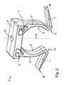
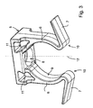
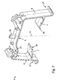
- the fastening device 2 which in the Fig. 2 and 3 is shown in detail, has a trained for the ceiling or wall mounting mounting portion 5, two provided on opposite sides of the mounting portion 5 retaining arms 6 and two of the support arms 6 end projecting support arms 7.
- the fastening device 2 is in particular made in one piece, for example, the fastening device 2 is made of a plastic material.
- a through-hole 8 is provided in the region of the mounting portion 5.
- the through-hole 8 is used in particular for receiving a screw, not shown, by means of which the fastening device 2 can be fixed to the ceiling or wall.
- the holding arms 6 of the fastening device 2 are elongated and slender. They have on facing inner sides 9 a circular arc-shaped geometry.
- the holding arms 6 are formed elastically bending.
- the support arms 7 are provided on one of the mounting portion 5 opposite side of the support arms 6.
- the support arms 7 are also elongated and slim.
- the support arms 7 are like the support arms 6 elastic.
- a transition radius 10 is formed in the transition region between the support arms 6 and the support arms 7, a transition radius 10 is formed.
- the transition radius 10 is dimensioned such that impermissible stresses in the fastening device 2 during elastic deformation of the support arms 7 or the retaining arms 6 are avoided.
- An elastic deformation of the support arms 6 is particularly favored by 6 two recesses 11 are formed in the transition region between the mounting portion 5 and the support arms. As a result of the recesses 11 improves the Elasticity of the fastening device 2, or the rigidity is reduced.
- the fastening device 2 is formed symmetrically with respect to a longitudinal central axis 12.
- the longitudinal center axis 12 there is both a point symmetry and an area symmetry with respect to a transverse center plane extending through the longitudinal center axis 12 and a longitudinal center plane extending through the longitudinal central axis 12.
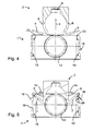
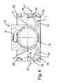
- the 4 to 6 show the installation of the lamp 1 to the fastening device 2 and the lamp 1 in a mounting position.
- the lamp 1 is attached in the mounting direction 3 to the fastening device 2.
- the lamp 1 provides for fixing the same to the fastening device 2, a cylindrical tube-shaped attachment portion 13 before.
- the holding arms 6 are elastically pressed in a deformation main direction 14 to the outside.
- the support arms 7 deform in contact with a housing outer wall 15 of the lamp 1 in a deformation auxiliary 16.
- the support arms 7 are in this case raised in the direction of the mounting portion 5 and approximated to the support arms 6.
- a contact zone 17 formed at the free ends of the support arms 7 contact area 18 of the support arms 7 is formed so that a self-retaining fixing the lamp 1 is given in the fastening device 2.
- the support arms 7 are pressed against the housing outer wall 15 as a result of contact with the housing outer wall 15 and the weight of the lamp 1 or an elastic restoring force of the retaining arms 6.
- the housing outer wall 15 defines insofar as a support portion 19 of the lamp. 1
- the support arms 7 are lifted against the deformation auxiliary 16 of the support portion 19. Subsequently, the lamp 1 can be removed from the mounting device 2 against the mounting direction 3. Upon removal, the holding arms 6 elastically deform in the main deformation direction 14.
- a mounting portion 20 Adjacent to the support portion 19 on which the support arms 7 are fixed self-holding in the mounting position, a mounting portion 20 is formed on the inside 9 of the housing outer wall 15.
- the mounting portion 20 provides a mounting surface in relation to the vertical at an acute angle. A self-locking of the support arms 7 in the region of the mounting portion 20 is not given, so that the support arms 7 can be performed with the contact portion 18 during assembly or disassembly of the lamp 1 along the mounting portion 20.
- a second fastening device 2 according to the invention according to Fig. 7 and 8th As before, it has a mounting section 5 with retaining arms 6 integrally formed on its end and supporting arms 7 protruding from the retaining arms 6.
- the support arms 7 face each other and each extend in the direction of the opposite support arm 6.
- a channel-shaped receiving trough 21 is formed on the retaining arms 6. The receiving trough 21 serves to carry the lamp 1 or the receiving a mounting portion 13 of the lamp first
- the support arms 6 and the support arms 7 are elongated and elastic. In a transition region between the support arms 6 and the mounting portion 5 reinforcing ribs 22 are provided, which are structurally designed so that the elasticity of the support arms 6 reaches a required level.
- the fastening device 2 according to the Fig. 7 and 8th is determined on a mounting rail 23.
- additional connecting means such as screws or the like are not required to fix the fastening device 2 to the mounting rail 23.
- FIG. 9 to 11 are shown fixing the fastening device 2 to the mounting rail 23 on the mounting portion 5 on a support arms 6 opposite side two groove-shaped recesses 24 are provided which engage around the mounting rail 23 from the outside.
- An attachment of the fastening device 2 to the mounting rail 23 in this case takes place by the fastening device 2 relative to the longitudinal center axis 12 rotated by an angle of approximately 30 ° attached to the mounting rail 23 and then rotated clockwise.
- a positional relationship between the mounting rail 23 and the fastening device 2 is achieved by a position cam 25, which is provided between the two groove-shaped recesses 24, is inserted into a longitudinal recess of the mounting rail 23.
- the lamp 1 can be mounted on the fastening device 2.
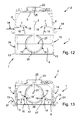
- the mounting situation and the assembled state are in the FIGS. 12 and 13 shown.
- the lamp 1 is then attached to the recess 4 to the fastening device 2.
- the support arms 7 are elastically deformed by the contact with the pipe section 26 in the deformation auxiliary 16.
- the lamp 1 is located with the housing outer wall 15 in the receiving wells 21, which are provided on the support arms 6.
- the support arms 6 are applied to the housing outer wall 15 from the inside.
- the receiving trough 21 facing portion of the housing outer wall 15 forms the attachment section 13 of the lamp 1.
- the support arms 7 are based with their free end to the pipe section 26 from.
- the contact zone 17 is in this case formed below a horizontal center plane 27 of the pipe section 26. Consequently, a positive engagement between the contact region 18 of the support arm 7 and the support portion 19 of the lamp 1 results.
- the support arms 7 In order to remove the luminaire 1 from the fastening device 2, the support arms 7 must first be raised in the deformation auxiliary direction 16. Subsequently, the lamp 1 can be raised so far that the attachment portion 13 of the housing outer wall 15 is provided outside of the receiving trough 21. The support arms 6 can then elastically deformed against each other and the lamp 1 are removed from the mounting device 2 against the mounting direction 3.
Landscapes
- Engineering & Computer Science (AREA)
- General Engineering & Computer Science (AREA)
- Connection Of Plates (AREA)
Priority Applications (1)
| Application Number | Priority Date | Filing Date | Title |
|---|---|---|---|
| EP14159689.0A EP2918907A1 (fr) | 2014-03-14 | 2014-03-14 | Dispositif de fixation d'une lampe |
Applications Claiming Priority (1)
| Application Number | Priority Date | Filing Date | Title |
|---|---|---|---|
| EP14159689.0A EP2918907A1 (fr) | 2014-03-14 | 2014-03-14 | Dispositif de fixation d'une lampe |
Publications (1)
| Publication Number | Publication Date |
|---|---|
| EP2918907A1 true EP2918907A1 (fr) | 2015-09-16 |
Family
ID=50277031
Family Applications (1)
| Application Number | Title | Priority Date | Filing Date |
|---|---|---|---|
| EP14159689.0A Withdrawn EP2918907A1 (fr) | 2014-03-14 | 2014-03-14 | Dispositif de fixation d'une lampe |
Country Status (1)
| Country | Link |
|---|---|
| EP (1) | EP2918907A1 (fr) |
Citations (5)
| Publication number | Priority date | Publication date | Assignee | Title |
|---|---|---|---|---|
| JPH04359804A (ja) * | 1991-06-05 | 1992-12-14 | Jiro Sugimoto | 照明器付属装置および照明装置 |
| US5971573A (en) * | 1997-05-24 | 1999-10-26 | King Of Fans, Inc. | Spring clip light fixture connector |
| EP1433997A2 (fr) * | 2002-12-24 | 2004-06-30 | Belux AG | Module d'éclairage électrique pour connexion en cascade comprenant au moins un tube fluorescent |
| DE202010000015U1 (de) * | 2009-01-08 | 2010-06-10 | Hsieh, Chen-Huang | Lampe in einem Rahmen |
| US20100321926A1 (en) * | 2008-04-10 | 2010-12-23 | Sharp Kabushiki Kaisha | Backlight for liquid crystal display |
-
2014
- 2014-03-14 EP EP14159689.0A patent/EP2918907A1/fr not_active Withdrawn
Patent Citations (5)
| Publication number | Priority date | Publication date | Assignee | Title |
|---|---|---|---|---|
| JPH04359804A (ja) * | 1991-06-05 | 1992-12-14 | Jiro Sugimoto | 照明器付属装置および照明装置 |
| US5971573A (en) * | 1997-05-24 | 1999-10-26 | King Of Fans, Inc. | Spring clip light fixture connector |
| EP1433997A2 (fr) * | 2002-12-24 | 2004-06-30 | Belux AG | Module d'éclairage électrique pour connexion en cascade comprenant au moins un tube fluorescent |
| US20100321926A1 (en) * | 2008-04-10 | 2010-12-23 | Sharp Kabushiki Kaisha | Backlight for liquid crystal display |
| DE202010000015U1 (de) * | 2009-01-08 | 2010-06-10 | Hsieh, Chen-Huang | Lampe in einem Rahmen |
Similar Documents
| Publication | Publication Date | Title |
|---|---|---|
| EP1593908B1 (fr) | Support pour lampe fluorescent | |
| EP2866612B1 (fr) | Tiroir | |
| DE102006007460A1 (de) | Verbindermontageaufbau | |
| DE10104906A1 (de) | Befestigungsvorrichtung für Heckleuchten von Fahrzeugen, vorzugsweise von Kraftfahrzeugen | |
| EP3875857A1 (fr) | Luminaire d'appareil de cuisson pourvu d'une tige guide lumière | |
| EP2566729B1 (fr) | Moteur d'essuie-glace avec élément de désaccouplement | |
| EP1856417B1 (fr) | Armature a capacite elevee destinee a connecter deux composants | |
| EP2756780B1 (fr) | Support pour les lattes d'un sommier avec tenon de retenue | |
| EP2354570B1 (fr) | Support de prise pour un point de fixation supérieur d'un composant pouvant être monté de manière suspendue | |
| EP3787932B1 (fr) | Agencement support pour un boîtier de capteur comprenant un élément d'attache et une butée | |
| DE102014104923A1 (de) | Karosseriestruktur mit einem Anbauelement und Verfahren zur Montage des Anbauelements an der Karosseriestruktur | |
| EP0525541B1 (fr) | Feu pour véhicule | |
| EP4354017A1 (fr) | Système de fixation pour une lampe, élément de fixation et lampe | |
| EP3250416B1 (fr) | Système de liaison séparable entre une première pièce et une deuxième pièce | |
| EP2215402B1 (fr) | Dispositif de mise à niveau pour monter une lampe de manière réglable en hauteur | |
| DE202015105569U1 (de) | In einem Gehäuse integrierbare Vorrichtung für Schiebetüren | |
| EP3106759B1 (fr) | Système de suspension pour la fixation d'un hotte aspirante | |
| EP2767659A2 (fr) | Guide à barres rondes réglable en hauteur | |
| DE202019106653U1 (de) | Trägervorrichtung für ein Außenverkleidungsteil eines Kraftfahrzeugs | |
| DE10234459B4 (de) | Verbindungselement zum Befestigen eines optischen Leuchtenbauteils an einer Leuchte und Leuchte | |
| DE4140362C2 (de) | Kraftfahrzeugleuchte | |
| EP2757546B1 (fr) | Tableau indicateur, notamment pour une installation d'éclairage de secours | |
| EP2735682B1 (fr) | Curseur | |
| DE102013010006B3 (de) | Befestigungsanordnung für einen Außenspiegel eines Fahrzeugs | |
| DE20207685U1 (de) | Halter |
Legal Events
| Date | Code | Title | Description |
|---|---|---|---|
| PUAI | Public reference made under article 153(3) epc to a published international application that has entered the european phase |
Free format text: ORIGINAL CODE: 0009012 |
|
| AK | Designated contracting states |
Kind code of ref document: A1 Designated state(s): AL AT BE BG CH CY CZ DE DK EE ES FI FR GB GR HR HU IE IS IT LI LT LU LV MC MK MT NL NO PL PT RO RS SE SI SK SM TR |
|
| AX | Request for extension of the european patent |
Extension state: BA ME |
|
| 17P | Request for examination filed |
Effective date: 20151030 |
|
| RBV | Designated contracting states (corrected) |
Designated state(s): AL AT BE BG CH CY CZ DE DK EE ES FI FR GB GR HR HU IE IS IT LI LT LU LV MC MK MT NL NO PL PT RO RS SE SI SK SM TR |
|
| GRAP | Despatch of communication of intention to grant a patent |
Free format text: ORIGINAL CODE: EPIDOSNIGR1 |
|
| INTG | Intention to grant announced |
Effective date: 20160503 |
|
| STAA | Information on the status of an ep patent application or granted ep patent |
Free format text: STATUS: THE APPLICATION IS DEEMED TO BE WITHDRAWN |
|
| 18D | Application deemed to be withdrawn |
Effective date: 20160914 |