EP2919085A2 - Method for operating a robot - Google Patents
Method for operating a robot Download PDFInfo
- Publication number
- EP2919085A2 EP2919085A2 EP15158379.6A EP15158379A EP2919085A2 EP 2919085 A2 EP2919085 A2 EP 2919085A2 EP 15158379 A EP15158379 A EP 15158379A EP 2919085 A2 EP2919085 A2 EP 2919085A2
- Authority
- EP
- European Patent Office
- Prior art keywords
- contour
- guide device
- robot arm
- web
- tool
- Prior art date
- Legal status (The legal status is an assumption and is not a legal conclusion. Google has not performed a legal analysis and makes no representation as to the accuracy of the status listed.)
- Withdrawn
Links
Images


Classifications
-
- G—PHYSICS
- G05—CONTROLLING; REGULATING
- G05B—CONTROL OR REGULATING SYSTEMS IN GENERAL; FUNCTIONAL ELEMENTS OF SUCH SYSTEMS; MONITORING OR TESTING ARRANGEMENTS FOR SUCH SYSTEMS OR ELEMENTS
- G05B19/00—Program-control systems
- G05B19/02—Program-control systems electric
- G05B19/42—Recording and playback systems, i.e. in which the program is recorded from a cycle of operations, e.g. the cycle of operations being manually controlled, after which this record is played back on the same machine
- G05B19/423—Teaching successive positions by walk-through, i.e. the tool head or end effector being grasped and guided directly, with or without servo-assistance, to follow a path
-
- B—PERFORMING OPERATIONS; TRANSPORTING
- B25—HAND TOOLS; PORTABLE POWER-DRIVEN TOOLS; MANIPULATORS
- B25J—MANIPULATORS; CHAMBERS PROVIDED WITH MANIPULATION DEVICES
- B25J9/00—Program-controlled manipulators
- B25J9/16—Program controls
- B25J9/1656—Program controls characterised by programming, planning systems for manipulators
- B25J9/1664—Program controls characterised by programming, planning systems for manipulators characterised by motion, path, trajectory planning
-
- G—PHYSICS
- G05—CONTROLLING; REGULATING
- G05B—CONTROL OR REGULATING SYSTEMS IN GENERAL; FUNCTIONAL ELEMENTS OF SUCH SYSTEMS; MONITORING OR TESTING ARRANGEMENTS FOR SUCH SYSTEMS OR ELEMENTS
- G05B2219/00—Program-control systems
- G05B2219/30—Nc systems
- G05B2219/36—Nc in input of data, input key till input tape
- G05B2219/36425—Move manually, touch surface, record position
-
- G—PHYSICS
- G05—CONTROLLING; REGULATING
- G05B—CONTROL OR REGULATING SYSTEMS IN GENERAL; FUNCTIONAL ELEMENTS OF SUCH SYSTEMS; MONITORING OR TESTING ARRANGEMENTS FOR SUCH SYSTEMS OR ELEMENTS
- G05B2219/00—Program-control systems
- G05B2219/30—Nc systems
- G05B2219/39—Robotics, robotics to robotics hand
- G05B2219/39216—Motion scaling
Definitions
- the invention relates to a method for operating a robot.
- Robots in general are handling machines that are equipped for the automatic handling of objects with appropriate tools and are programmable in several axes of motion, in particular with regard to orientation, position and workflow.
- Robots typically include a multi-limb robotic arm and programmable controllers (control devices) that automatically control the movements of the robotic arm during an automatic operation.
- the drives are e.g. electric drives and the links are in particular rotatably mounted relative to each other with respect to axes.
- control device controls the robot arm such that the tool attached to the robot arm is automatically moved along a predetermined path.
- the robot or its control device is suitably programmed.
- the object of the present invention is to specify an improved method for programming and therefore also for operating a robot.
- the robot is programmed with the aid of the physical object, so that it is capable of automatically moving the tool along the path in its automatic mode.
- the tool As the tool is moved automatically along the path, it preferably processes a workpiece automatically.
- Machining is eg gluing, welding or milling.
- the tool is eg a milling head, a glue tip, a polishing head.
- the robot is eg a lightweight robot and / or preferably force / torque-controlled.
- the physical object in turn comprises the surface provided with the contour. Their course is assigned to the course of the track, so that the object makes it possible to program the robot in a suitable manner.
- the surface can be two-dimensional, two-and-a-half-dimensional, that is curved, or even three-dimensional.
- the physical object is preferably created by means of a 3D print.
- the guide device is used, which is attached to the programming device on the attachment device of the robot arm.
- the guiding device may e.g. be attached to the fastening device instead of the tool.
- the tool comprises the guide device.
- the guiding device in this case is e.g. Angled attached to the part of the tool, which is intended to edit the workpiece.
- the guide device interacts with the contour in a form-fitting manner so that, according to an embodiment of the method according to the invention, it is possible to move the robot arm by manual guidance so that the guide device is moved along the course of the contour from the starting point to the end point of the contour.
- Manual guiding is understood to mean that a person manually moves the robot arm by pulling and / or pushing on its structure.
- the robot arm comprises, in particular, force and / or moment sensors connected to the control device, which force or torque at the individual Determine limbs.
- This makes it possible for the control device for moving the robot to control drives provided during the manual guidance of the robot arm in such a way that they at least support the movements of the individual links resulting from the manual guidance.
- the robot is in this case preferably force and / or torque-controlled.
- This information may also include corresponding positions of the individual members of the robotic arm relative to each other.
- control device Since the course of the contour is associated with the course of the web, the control device is enabled on the basis of the information about the positions or orientations of the guide device during automatic operation to control the robot arm such that the tool attached to the robot arm automatically the train follows.
- the robot arm controlled by the control device, is moved automatically in such a way that the guide device is automatically moved along the course of the contour from the starting point to the end point of the contour.
- the robot is in particular force and / or torque-controlled executed, preferably with respect to all its members, and thus able to follow the contour tactile.
- the course of the contour may differ from the course of the web by a scale other than 1.0.
- the control device on the basis of information about this scale in automatic mode, moves the robot arm in such a way that the tool is automatically moved along the path of the web.
- This yardstick can be used for the calculation of the web, e.g. be already stored in the control device or it can be entered into the control device.
- the latter comprises determining the scale by approaching mutually corresponding reference points of a workpiece to be machined during the automatic operation by means of the tool and of the object by means of the guide device and / or the tool and determining the scale based on the distances between the reference points of the object and the workpiece.
- the reference points are e.g. the corresponding start and end points of the object and the path.
- the optionally necessary scaling can thus take place, for example, on the software side, or via approaching corner points of the physical object, for example, a template and the workpiece intended for machining, and thus automatically. Also starting up the start and end points of the physical object and possibly the workpiece results in an automatic scaling.
- the contour may e.g. be designed as a recess, in particular as a slot.
- the recess or slot may be e.g. produced by milling.
- the guide device preferably comprises a guide pin or is designed as a guide pin, which is able to engage positively in the recess.
- the contour can also be designed as an elevation, in particular as a rail, on the surface.
- the guide device is then preferably designed to encompass the increase in a form-fitting manner.
- the contour is formed as a rail with a T-shaped cross-section.
- the guide device is preferably designed such that it is capable of embracing the rail provided with the T-shaped cross-section in a form-fitting manner.
- the construction of the guide rails merely allows the guide device to be moved along the T-section cross-section, thereby facilitating not only manual guidance of the robot arm but also automatic movement of the guide along the contour.
- the contour may have a first physical switching structure at the starting point of the contour and a second physical switching structure at the end point of the contour.
- the guiding device can be designed such that it can interact with the switching structures in such a way that, when the first switching structure is moved over with the guiding device, the information about the positions or positions which the guiding device moves during the movement along the course of the guiding device Contour takes, begins and / or when driving over the second switching structure with the guide device storing the information about the positions or positions occupied by the guide device during movement along the contour of the contour.
- a user can create the web programming himself with relatively simple aids. This can e.g. semi-automatic with manual guidance.
- the adjuvants include e.g. the physical object is associated with the path associated contour, e.g. milled, glued or produced by means of a 3D print.
- the aids comprise the guiding device e.g. in the form of a process tool with teach adapter, which is the counterpart to the contour.
- the contact surfaces between the contour and the guide device can be designed friction optimized.
- the teach adapter or the guide device is preferably moved along the contour in manual guidance and recorded.
- the physical object is preferably in a reproducible position e.g. clamped by a suitable device.
- the automatic mode can be started eg via start / stop of the process via a manual control button (eg adhesive nozzle on / off).
- a manual control button eg adhesive nozzle on / off.
- the contour can for example be glued or manufactured by means of a 3D printing.
- the contour is e.g. designed as a T-shaped rail.
- the teaching adapter or the guiding device are threaded into the contour at the starting point.
- the physical object is preferably in a reproducible position e.g. clamped by a suitable device.
- the starting direction can be defined via the teach adapter or the guide device.
- the robot is preferably force-controlled and brings in the starting direction (tool coordinate system) a desired force along the contour and switches the remaining degrees of freedom soft.
- the robot automatically follows the path predetermined in the physical object by the shape contour up to the end point.
- contour switching cams for on / off of process functions can be incorporated.
- the movement can be stopped automatically via control cams on the contour of the mold.
- Process parameters e.g., speed, force
- Process parameters e.g., speed, force
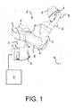
- the Fig. 1 shows a robot 1, in particular as a lightweight robot, which comprises a robot arm 2 and a control device 3.
- the robot arm 2 in the case of the present embodiment, a plurality of successively arranged and connected by means of joints 4 links 5.
- the robot arm 2 comprises a fastening device designed as a flange 6 for fastening a fastening device in the Fig. 2 closer illustrated tool 7.
- the links 5 may be relative to each other e.g. be moved with respect to axes of rotation A.
- the robot 1 also has not shown drives, which are preferably designed as electrical drives, in particular as a regulated electric drives. At least the electric motors of the electric drives, also not shown in detail, are arranged in or on the robot arm 2. Power electronics of the electric drives are e.g. within a housing of a control cabinet, not shown, within the e.g. also the control device 3 is arranged. At least parts of the power electronics can also be arranged in or on the robot arm 2.
- a Tool Center Point (TCP) 14 of the tool 7 automatically performs a predetermined movement, in particular one in the Fig. 3 shown workpiece 8 to edit.
- TCP Tool Center Point
- the control device 2 is intended to move the robot arm 2 by means of the computer program in such a way that the tool 7 or its tool center point 14 for processing the workpiece 8 has a predetermined path 9 from a starting point 9a of the web 8 to a End point 9b of the web 9 automatically departs.
- the machining of the workpiece 8 may be, for example, an adhesive or a welding process or a milling process.
- the computer program provided for controlling the movement of the robot arm 1 during the automatic program is assisted of the robot 1 and one in the Fig. 3 shown physical object 18 created.
- the physical object 18 comprises a surface 20 which is provided with a contour 19.
- the surface 20 is for example flat, as in the in the Fig. 3 the embodiment shown is the case.
- the surface 20 may also be curved or have at least one edge.
- the surface 20 of the physical object 18 is provided with a contour 19 whose course along the surface 20 is assigned to the course of the web 9 or corresponds to the course of the web 20.
- the contour 19 comprises a starting point 19a associated with the starting point 9a of the track 9 and an end point 19b associated with the end point 9b of the track 9.
- the contour 19 may be e.g. be designed as a recess 21 in the surface 20. However, the contour 19 may be e.g. also be executed as an increase on the surface 20.
- the contour 19, which is in the form of a depression 21, may be e.g. be made by milling.
- the physical object 18 may preferably have been produced by means of a 3D printer.
- the tool 7 is provided with a guide device 10 in the case of the present embodiment.
- the guide device 10 may be formed, for example, as a guide pin 11, as shown in the Fig. 2 is shown.
- the guide device 10 and the guide pin 11 and the workpiece 7 are at a known angle ⁇ , which is preferably 90 °, aligned with each other.
- ⁇ which is preferably 90 °, aligned with each other.
- the guide device 10 instead of the tool 7 for creating of the computer program is attached to the flange 6 of the robot arm 3.
- the guide device 10 also has a tool center point 15.
- the robot arm 2 is moved in particular by manual guidance such that the guide device 10, in particular the tip 11a of the guide pin 11 at the starting point 19a of the contour 19 or the recess 21 of the physical object 18th has arrived.
- Manual guiding is understood to mean that a person manually moves the robot arm 2 by pulling and / or pushing on its structure.
- the robot arm 2 comprises in particular force and / or moment sensors connected to the control device 3, which determine the forces or torques on the individual links 5.
- This makes it possible for the control device 3 to control the drives during manual guidance of the robot arm 2 in such a way that they at least support the movements of the individual links 5 that arise as a result of manual guidance.
- the person moves by manual guidance of the robot arm 2, the guide device 10 and the guide pin 11 along the contour 19 to the end point 19b of the contour 19.
- the control device 3 stores information about the position, possibly also about the orientation, which the guide device 11 or its tool center point 15 occupy during its movement along the contour 19. This information is recorded, for example, in discrete steps. This information can also be recorded by means of the corresponding positions of the axes A of the robot arm 2.
- the guide device 10 and the contour 19 or the guide pin 11 and the recess 21 are matched to each other, so that they preferably cooperate positively and / or non-positively.
- the guide device 10 can be improved along the contour 19 manually.
- the robot arm 3, controlled by the control device 2 automatically moves the guide device 10 along the contour 19 until the guide device 10 reaches the end point 19b.
- the contour 19 guides the guide device 10. The person leading the robot arm 3 manually can press the guide device 10 against the contour 19 at the starting point 19a of the contour 19 with a certain minimum force.
- the robot arm 3 can then automatically follow the contour 19 up to its end point 19b in order to obtain information about the position, if necessary also the orientation, of the guide device 11 or its tool center point 15 during its movement along the Contains contour 19 to save.
- the guide device 11 is fastened to the flange 6 of the robot arm 3, the recorded positions or positions of the axes A, possibly adjusted by scaling, already correspond to positions or positions of the tool center point 14 of the tool 7 or positions of the axes A during the automatic mode. If, however, the guide device 10 is attached to the tool 7, then it is the control device 3 due to the knowledge of the relative orientation of the guide device 10 relative to the tool 7 possible, the corresponding Positions, positions of the axes A to calculate. This can be done during the manual guidance of the robot arm 2 or during the automatic movement of the robot arm 2 or also after the completion of the corresponding movement of the robot arm 2.
- control device 2 receives the information about the positions or positions that the robot arm 3 or the tool 7 should assume during the automatic operation.
- This scale can e.g. already stored in the control device 3 or can be entered in this.
- this scaling or the determination of the scale takes place by starting, preferably by manually guiding the robot arm 2, by at least two pairs of mutually corresponding reference points 12, 22, 13, 23 of the workpiece 8 and of the object 18
- the reference points 12, 22, 13, 23 are, for example, the starting points 19a, 9a and the end points 19b, 9b of the contour 19 and the path 9.
- the scale can then be determined on the basis of the distances between the reference points of the object 18 and the workpiece 8.
- the tool 7 is moved by manually guiding the robot arm 2 to the starting point 9a of the web 9 and then the automatic operation of the robot 1 is started. If the position or position of the workpiece 8 is known, it is also possible for the robot arm 2, controlled by the control device 3, to automatically move the tool 7 toward the workpiece 8 in the course of the automatic mode, in order to subsequently machine it.
- the contour 19 can also run along a curved surface.
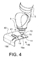
- the Fig. 4 shows a part of the robot arm 2 with its flange 6 and another physical object 48, which has a curved surface 40.
- This surface 40 is provided with the contour 19, which in the in the Fig. 4 shown embodiment as a recess or as a slot 41 in the surface 40 is executed.
- This physical object 48 is likewise provided for programming the robot 1, wherein the contour 19 is likewise assigned to a path which the robot 1 is to travel after programming in automatic mode.
- the physical object 48 has been e.g. produced by a 3D print.
- the recess or slot 41 may also have been made by milling into the surface 40.
- the guide device 10 can also be fastened to the flange 6 instead of the tool 7 provided for the machining of the workpiece 8.
- An example of such an embodiment is in Fig. 4 shown.
- the in the Fig. 4 Illustrated guide device 10 also includes the guide pin 11 or is executed as the guide pin 11, which is preferably moved for programming the robot 1 from the starting point 19a to the end point 19b of the contour 19 along the contour 19 designed as a slot 41 by manually guiding the robot arm 3.
- Trained as a guide pin 11 guide device 10 is adapted to the designed as a slot 41 contour 19, preferably adapted so that it cooperates positively with the slot 41.
- the position of the tool center point 15 of the guide device 10 or of the guide pin 11 corresponds to the position of the tool center point 14 of the tool 7, which is fastened to the flange 6 of the robot arm 3 during the automatic operation.
- the contact surfaces between the guiding device 10 formed as a guide pin 11 and the contour 19 formed as a slot 41 are preferably designed such that they cause as little friction as possible.
- the contour 19 can also be designed as an elevation on the surface of the physical object.
- An example of such an embodiment is in Fig. 5 which shows a physical object 58 with a surface 50 which, instead of the one shown in FIG Figures 3 and 4 shown physical objects 18, 48 can be used to program the robot 1.
- the surface 50 of the in the Fig. 5 shown physical object 58 is provided with an executed as an increase contour 19.
- the physical object 58 was preferably generated by means of a 3D print.
- the contour 19 designed as an increase may have been glued to the surface 50, for example, or likewise produced by 3D printing.
- the executed as an increase contour 19 is in the case of in the Fig. 5 1, along which the guide device 10 is moved by means of the robot 1 from the starting point 19a to the end point 19b of the programming contour 19, preferably by means of manual guiding.
- the guide device 10 is fastened to the flange 6 of the robot arm 2 during programming instead of the tool 7.
- the flange 6 facing away from the end 52 of the guide device 10 is designed such that it is able to engage positively in the running as a rail 51 contour 19.
- the contact surfaces between the guide device 10 and the guide device 10 formed as a rail 51 are preferably designed such that they cause as little friction as possible.
- FIG. 12 shows another alternative embodiment of a physical object 68 that may be used to program the robot 1 instead of the previously described physical objects 18, 48, 58.
- FIG. 6 shown physical object 68 differs from that in the Fig. 5 shown physical object 58 in that the running as a rail 51 contour 19 have physical switching structures, which are assigned to the starting point 19a and the end point 19b of the contour 19.
- the physical switching structure associated with the starting point 19a is designed as a cam 61, which is formed on the rail 51 at the starting point 19a.
- the associated with the end point 19b Physical switching structure is carried out in the case of the present embodiment as a notch 62, which is inserted into the rail 51 at the end point 19b.
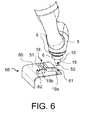
- FIG. 12 shows another alternative embodiment of a physical object 78 which may be used to program the robot 1 instead of the previously described physical objects 18, 48, 58, 58.
- FIG. 7 shown physical object 78 differs from that in the Fig. 5 shown physical object 58 in that the designed as a rail 71 contour 19 has a cross-sectionally T-shaped profile and that the flange 6 remote from the end 72 of the guide device 10 is designed such that it surrounds the T-shaped end of the guide rail 71 able to encompass in particular positive and / or non-positive. This ensures that the guide device 10 is movable only along the rail 71. This possibly facilitates not only the manual guiding but also an automatic movement of the guide device 10 along the rail 71 by means of the robot 1 or the robot arm 2.
- the rail 71 may also be provided with the physical switching structures.
Landscapes
- Engineering & Computer Science (AREA)
- Robotics (AREA)
- Mechanical Engineering (AREA)
- Physics & Mathematics (AREA)
- General Physics & Mathematics (AREA)
- Automation & Control Theory (AREA)
- Manipulator (AREA)
Abstract
Die Erfindung betrifft ein Verfahren zum Betreiben eines Roboters (1) unter Verwendung eines physikalischen Objekts (18, 48, 58, 68, 78). Der Roboter (1) umfasst einen Roboterarm (2) mit mehreren, hintereinander angeordneten Gliedern (5) und mit einer Befestigungsvorrichtung (6), sowie eine Steuerungsvorrichtung (3) zum Bewegen des Roboterarms. Das physikalisches Objekt (18, 48, 58, 68, 78) umfasst eine Oberfläche (20, 40, 50), die mit einer Kontur (19) versehen ist, deren Verlauf einem Verlauf einer Bahn (9) zugeordnet ist, entlang derer in einem Automatikbetrieb die Steuervorrichtung den Roboterarm (2) derart ansteuern soll, sodass der Roboterarm (2) automatisch ein an der Befestigungsvorrichtung (6) befestigtes Werkzeug (7) entlang des Verlaufs der Bahn (9) von einem Startpunkt (9a) der Bahn (9) zu einem Endpunkt (9b) der Bahn (9) bewegt.The invention relates to a method for operating a robot (1) using a physical object (18, 48, 58, 68, 78). The robot (1) comprises a robot arm (2) with a plurality of members (5) arranged one behind the other and with a fastening device (6), and a control device (3) for moving the robot arm. The physical object (18, 48, 58, 68, 78) comprises a surface (20, 40, 50) which is provided with a contour (19) whose course is associated with a path of a web (9) along which an automatic operation, the control device is intended to control the robot arm (2) in such a way that the robot arm (2) automatically moves a tool (7) fastened to the fastening device (6) along the path of the web (9) from a starting point (9a) of the web (9 ) to an end point (9b) of the web (9).
Description
Die Erfindung betrifft ein Verfahren zum Betreiben eines Roboters.The invention relates to a method for operating a robot.
Roboter im Allgemeinen sind Handhabungsmaschinen, die zur selbsttätigen Handhabung von Objekten mit zweckdienlichen Werkzeugen ausgerüstet und in mehreren Bewegungsachsen insbesondere hinsichtlich Orientierung, Position und Arbeitsablauf programmierbar sind. Roboter weisen üblicherweise einen Roboterarm mit mehreren Gliedern und programmierbare Steuerungen (Steuervorrichtungen) auf, die während eines Automatikbetriebs die Bewegungsabläufe des Roboterarms automatisch steuern bzw. regeln. Die Antriebe sind z.B. elektrische Antriebe und die Glieder sind insbesondere relativ zueinander bezüglich Achsen drehbar gelagert.Robots in general are handling machines that are equipped for the automatic handling of objects with appropriate tools and are programmable in several axes of motion, in particular with regard to orientation, position and workflow. Robots typically include a multi-limb robotic arm and programmable controllers (control devices) that automatically control the movements of the robotic arm during an automatic operation. The drives are e.g. electric drives and the links are in particular rotatably mounted relative to each other with respect to axes.
Insbesondere steuert im Automatikbetrieb die Steuervorrichtung den Roboterarm derart an, dass das am Roboterarm befestigte Werkzeug automatisch entlang einer vorgegebenen Bahn bewegt wird. Dazu wird der Roboter bzw. dessen Steuervorrichtung geeignet programmiert.In particular, in automatic mode, the control device controls the robot arm such that the tool attached to the robot arm is automatically moved along a predetermined path. For this purpose, the robot or its control device is suitably programmed.
Die Aufgabe der vorliegenden Erfindung ist es, ein verbessertes Verfahren zum Programmieren und demnach auch zum Betreiben eines Roboters anzugeben.The object of the present invention is to specify an improved method for programming and therefore also for operating a robot.
Die Aufgabe der Erfindung wird gelöst durch ein Verfahren zum Betreiben eines Roboters, der einen Roboterarm mit mehreren, hintereinander angeordneten Gliedern und mit einer Befestigungsvorrichtung, sowie eine Steuerungsvorrichtung zum Bewegen des Roboterarms aufweist, unter Verwendung eines physikalisches Objekt, das eine Oberfläche umfasst, die mit einer Kontur versehenen ist, deren Verlauf einem Verlauf einer Bahn zugeordnet ist, entlang derer in einem Automatikbetrieb die Steuervorrichtung den Roboterarm derart ansteuern soll, sodass der Roboterarm automatisch ein an der Befestigungsvorrichtung befestigtes Werkzeug entlang des Verlaufs der Bahn von einem Startpunkt der Bahn zu einem Endpunkt der Bahn bewegt, aufweisend folgende Verfahrensschritte:
- Heranbewegen einer an der Befestigungsvorrichtung befestigten Führungsvorrichtung insbesondere durch manuelles Führen des Roboterarms an einen dem Startpunkt der Bahn zugeordneten Startpunkt der Kontur, wobei die Führungsvorrichtung eingerichtet ist, mit der Kontur formschlüssig zusammen zu wirken,
- Bewegen des Roboterarms derart, sodass die Führungsvorrichtung entlang des Verlaufs der Kontur von deren Startpunkt zu einem dem Endpunkt der Bahn zugeordneten Endpunkt der Kontur bewegt wird,
- Speichern einer Information über die Positionen oder Lagen, die die Führungsvorrichtung während der Bewegung entlang des Verlaufs der Kontur einnimmt, und
- Heranbewegen des an der Befestigungsvorrichtung befestigten Werkzeugs insbesondere durch manuelles Führen des Roboterarms an den Startpunkt der Bahn, sodass der Roboterarm im Automatikbetrieb, gesteuert durch die Steuervorrichtung, das Werkzeug entlang des Verlaufs der Bahn von deren Startpunkt zu deren Endpunkt aufgrund der Information über die Positionen oder Lagen, die die Führungsvorrichtung während der Bewegung entlang des Verlaufs der Kontur einnahm, automatisch bewegt.
- Moving a guide device fastened to the fastening device, in particular by manually guiding the robot arm to a starting point of the contour assigned to the starting point of the web, wherein the guiding device is set up to interact with the contour in a form-fitting manner,
- Moving the robot arm such that the guide device is moved along the course of the contour from its starting point to an end point of the contour assigned to the end point of the path,
- Storing information about the positions or postures occupied by the guide device during movement along the contour of the contour, and
- Moving the attached to the fastening device tool in particular by manually guiding the robot arm to the starting point of the web, so that the robot arm in the automatic mode, controlled by the control device, the tool along the course of the web from the starting point to the end point due to the information about the positions or Layers, which occupied the guide device during movement along the contour of the contour, automatically moves.
Gemäß dem erfindungsgemäßen Verfahren wird u.a. der Roboter unter Zuhilfenahme des physikalischen Objekts programmiert, sodass dieser in seinem Automatikbetrieb das Werkzeug entlang der Bahn automatisch zu bewegen vermag. Während das Werkzeug entlang der Bahn automatisch bewegt wird, bearbeitet es vorzugsweise ein Werkstück automatisch. Eine solche Bearbeitung ist z.B. ein Kleben, Schweißen oder Fräsen. Das Werkzeug ist z.B. ein Fräskopf, eine Klebespitze, ein Polierkopf. Der Roboter ist z.B. ein Leichtbauroboter und/oder vorzugsweise kraft-/momentengeregelt.According to the method according to the invention, among other things, the robot is programmed with the aid of the physical object, so that it is capable of automatically moving the tool along the path in its automatic mode. As the tool is moved automatically along the path, it preferably processes a workpiece automatically. Such Machining is eg gluing, welding or milling. The tool is eg a milling head, a glue tip, a polishing head. The robot is eg a lightweight robot and / or preferably force / torque-controlled.
Das physikalische Objekt umfasst wiederum die Oberfläche, die mit der Kontur versehen ist. Deren Verlauf ist dem Verlauf der Bahn zugeordnet, sodass das Objekt es ermöglicht, den Roboter in geeigneter Weise zu programmieren. Die Oberfläche kann zweidimensional, zweieinhalbdimensional, also gekrümmt, oder auch dreidimensional sein. Das physikalische Objekt ist vorzugsweise mittels eines 3D-Drucks erstellt.The physical object in turn comprises the surface provided with the contour. Their course is assigned to the course of the track, so that the object makes it possible to program the robot in a suitable manner. The surface can be two-dimensional, two-and-a-half-dimensional, that is curved, or even three-dimensional. The physical object is preferably created by means of a 3D print.
Für die Programmierung wird außerdem die Führungsvorrichtung verwendet, welche für die Programmierung an der Befestigungsvorrichtung des Roboterarms befestigt ist. Die Führungsvorrichtung kann z.B. anstelle des Werkzeugs an der Befestigungsvorrichtung befestigt sein. Es ist aber auch möglich, dass das Werkzeug die Führungsvorrichtung umfasst. Die Führungsvorrichtung ist in diesem Fall z.B. abgewinkelt zu dem Teil des Werkzeugs befestigt, der zum Bearbeiten des Werkstücks vorgesehen ist.For programming also the guide device is used, which is attached to the programming device on the attachment device of the robot arm. The guiding device may e.g. be attached to the fastening device instead of the tool. But it is also possible that the tool comprises the guide device. The guiding device in this case is e.g. Angled attached to the part of the tool, which is intended to edit the workpiece.
Erfindungsgemäß wirkt die Führungsvorrichtung formschlüssig mit der Kontur zusammen, sodass es gemäß einer Ausführungsform des erfindungsgemäßen Verfahrens erleichtert möglich ist, den Roboterarms durch manuelles Führen derart zu bewegen, sodass die Führungsvorrichtung entlang des Verlaufs der Kontur vom Startpunkt zum Endpunkt der Kontur bewegt wird.According to the invention, the guide device interacts with the contour in a form-fitting manner so that, according to an embodiment of the method according to the invention, it is possible to move the robot arm by manual guidance so that the guide device is moved along the course of the contour from the starting point to the end point of the contour.
Unter manuellem Führen wird verstanden, dass eine Person den Roboterarm durch Ziehen und/oder Drücken an seiner Struktur manuell bewegt. Der Roboterarm umfasst dazu insbesondere mit der Steuervorrichtung verbundene Kraft- und/oder Momentensensoren, welche die Kräfte bzw. Drehmomente an den einzelnen Gliedern ermitteln. Dadurch ist es möglich, dass während des manuellen Führens des Roboterarms die Steuervorrichtung zum Bewegen des Roboters vorgesehene Antriebe derart ansteuert, dass diese die durch das manuelle Führen entstehenden Bewegungen der einzelnen Glieder zumindest unterstützen. Der Roboter ist in diesem Fall vorzugsweise kraft- und/oder momentengeregelt.Manual guiding is understood to mean that a person manually moves the robot arm by pulling and / or pushing on its structure. For this purpose, the robot arm comprises, in particular, force and / or moment sensors connected to the control device, which force or torque at the individual Determine limbs. This makes it possible for the control device for moving the robot to control drives provided during the manual guidance of the robot arm in such a way that they at least support the movements of the individual links resulting from the manual guidance. The robot is in this case preferably force and / or torque-controlled.
Aufgrund des Formschlusses zwischen der Führungsvorrichtung und der Kontur wird es somit der Person erleichtert ermöglicht, mit der Führungsvorrichtung der Kontur zuverlässig zu folgen.Due to the positive connection between the guide device and the contour, it is thus made easier for the person to reliably follow the contour of the guide device.
Während dieser Bewegung wird außerdem eine Information über die Positionen oder Lagen, die die Führungsvorrichtung während der Bewegung entlang des Verlaufs der Kontur einnimmt, gespeichert. Diese Information kann auch entsprechende Stellungen der einzelnen Glieder des Roboterarms relativ zueinander umfassen.During this movement, information about the positions or positions taken by the guiding device during the movement along the contour of the contour is also stored. This information may also include corresponding positions of the individual members of the robotic arm relative to each other.
Da der Verlauf der Kontur dem Verlauf der Bahn zugeordnet ist, ist es der Steuervorrichtung aufgrund der Information über die Positionen bzw. Lagen (= Positionen und Orientierungen) der Führungsvorrichtung ermöglicht, während des Automatikbetriebs den Roboterarm derart anzusteuern, sodass das am Roboterarm befestigte Werkzeugt automatisch der Bahn folgt.Since the course of the contour is associated with the course of the web, the control device is enabled on the basis of the information about the positions or orientations of the guide device during automatic operation to control the robot arm such that the tool attached to the robot arm automatically the train follows.
Gemäß einer Ausführungsform des erfindungsgemäßen Verfahrens kann es auch vorgesehen sein, dass der Roboterarm, gesteuert durch die Steuervorrichtung, derart automatisch bewegt wird, sodass die Führungsvorrichtung entlang des Verlaufs der Kontur vom Startpunkt zum Endpunkt der Kontur automatisch bewegt wird. Der Roboter ist insbesondere kraft- und/oder momentengeregelt ausgeführt, vorzugsweise bezüglich all seiner Glieder, und vermag somit der Kontur taktil zu folgen.According to one embodiment of the method according to the invention, it can also be provided that the robot arm, controlled by the control device, is moved automatically in such a way that the guide device is automatically moved along the course of the contour from the starting point to the end point of the contour. The robot is in particular force and / or torque-controlled executed, preferably with respect to all its members, and thus able to follow the contour tactile.
Der Verlauf der Kontur kann sich von dem Verlauf der Bahn um einen Maßstab ungleich 1,0 unterscheiden. Gemäß einer Ausführungsform des erfindungsgemäßen Verfahrens kann es vorgesehen sein, dass die Steuervorrichtung aufgrund einer Information über diesen Maßstab im Automatikbetrieb den Roboterarm derart bewegt, sodass das Werkzeug automatisch entlang des Verlaufs der Bahn bewegt wird.The course of the contour may differ from the course of the web by a scale other than 1.0. According to one embodiment of the method according to the invention, it may be provided that the control device, on the basis of information about this scale in automatic mode, moves the robot arm in such a way that the tool is automatically moved along the path of the web.
Dieser Maßstab kann für die Berechnung der Bahn z.B. in der Steuervorrichtung bereits hinterlegt sein oder er kann in die Steuervorrichtung eingegeben werden.This yardstick can be used for the calculation of the web, e.g. be already stored in the control device or it can be entered into the control device.
Gemäß einer bevorzugten Ausführungsform des erfindungsgemäßen Verfahrens weist dieses jedoch ein Ermitteln des Maßstabs durch ein Anfahren von zueinander korrespondierenden Referenzpunkten eines während des Automatikbetriebs mittels des Werkzeugs zu bearbeitenden Werkstücks und des Objekts mittels der Führungsvorrichtung und/oder des Werkzeugs und ein Ermitteln des Maßstabs aufgrund der Abstände zwischen den Referenzpunkten des Objekts und des Werkstücks auf. Die Referenzpunkte sind z.B. die entsprechenden Start- und Endpunkte des Objekts und der Bahn.However, according to a preferred embodiment of the method according to the invention, the latter comprises determining the scale by approaching mutually corresponding reference points of a workpiece to be machined during the automatic operation by means of the tool and of the object by means of the guide device and / or the tool and determining the scale based on the distances between the reference points of the object and the workpiece. The reference points are e.g. the corresponding start and end points of the object and the path.
Die gegebenenfalls nötige Skalierung kann somit z.B. softwareseitig, oder über Anfahren von Eckpunkten des z.B. als Schablone ausgeführten physikalischen Objekts und des für eine Bearbeitung vorgesehenen Werkstücks, und somit automatisch, erfolgen. Auch ein Anfahren der Start- und Endpunkte des physikalischen Objekts und gegebenenfalls des Werkstücks ergibt eine automatische Skalierung.The optionally necessary scaling can thus take place, for example, on the software side, or via approaching corner points of the physical object, for example, a template and the workpiece intended for machining, and thus automatically. Also starting up the start and end points of the physical object and possibly the workpiece results in an automatic scaling.
Die Kontur kann z.B. als eine Vertiefung, insbesondere als ein Schlitz, ausgeführt sein. Die Vertiefung bzw. der Schlitz kann z.B. durch Fräsen erzeugt worden sein. In diesem Fall umfasst die Führungsvorrichtung vorzugsweise einen Führungsstift oder ist als ein Führungsstift ausgebildet, der formschlüssig in die Vertiefung einzugreifen vermag.The contour may e.g. be designed as a recess, in particular as a slot. The recess or slot may be e.g. produced by milling. In this case, the guide device preferably comprises a guide pin or is designed as a guide pin, which is able to engage positively in the recess.
Die Kontur kann auch als eine Erhöhung, insbesondere als eine Schiene, auf der Oberfläche ausgebildet sein. Die Führungsvorrichtung ist dann vorzugsweise ausgebildet, die Erhöhung formschlüssig zu umgreifen.The contour can also be designed as an elevation, in particular as a rail, on the surface. The guide device is then preferably designed to encompass the increase in a form-fitting manner.
Vorzugsweise ist die die Kontur als eine Schiene mit einem T-förmigen Querschnitt ausgebildet. In diesem Fall ist die Führungsvorrichtung vorzugsweise derart ausgebildet, dass sie die mit dem T-förmigen Querschnitt versehene Schiene formschlüssig zu umgreifen vermag. In diesem Fall erlaubt die Konstruktion der Führungsschien als solche lediglich ein Bewegen der Führungsvorrichtung entlang der Schiene mit dem T-förmigen Querschnitt, wodurch nicht nur ein manuelles Führen des Roboterarm erleichtert wird, sondern auch ein automatisches Bewegen der Führungsvorrichtung entlang der Kontur.Preferably, the contour is formed as a rail with a T-shaped cross-section. In this case, the guide device is preferably designed such that it is capable of embracing the rail provided with the T-shaped cross-section in a form-fitting manner. As such, in this case, the construction of the guide rails merely allows the guide device to be moved along the T-section cross-section, thereby facilitating not only manual guidance of the robot arm but also automatic movement of the guide along the contour.
Die Kontur kann am Startpunkt der Kontur eine erste physikalische Schaltstruktur und am Endpunkt der Kontur eine zweite physikalische Schaltstruktur aufweisen. In diesem Fall kann die Führungsvorrichtung derart ausgebildet sein, dass sie mit den Schaltstrukturen derart zusammen wirken vermag, sodass bei einem Überfahren der ersten Schaltstruktur mit der Führungsvorrichtung das Speichern der Information über die Positionen oder Lagen, die die Führungsvorrichtung während der Bewegung entlang des Verlaufs der Kontur einnimmt, beginnt und/oder bei einem Überfahren der zweiten Schaltstruktur mit der Führungsvorrichtung das Speichern der Information über die Positionen oder Lagen, die die Führungsvorrichtung während der Bewegung entlang des Verlaufs der Kontur einnimmt, beendet wird.The contour may have a first physical switching structure at the starting point of the contour and a second physical switching structure at the end point of the contour. In this case, the guiding device can be designed such that it can interact with the switching structures in such a way that, when the first switching structure is moved over with the guiding device, the information about the positions or positions which the guiding device moves during the movement along the course of the guiding device Contour takes, begins and / or when driving over the second switching structure with the guide device storing the information about the positions or positions occupied by the guide device during movement along the contour of the contour.
Je nach Ausführungsform des erfindungsgemäßen Verfahrens kann sich somit ein Verfahren zur halb- oder vollautomatischen reproduzierbaren Bahnprogrammierung von insbesondere kraftgeregelten Robotern ergeben.Depending on the embodiment of the method according to the invention, a method for semi-automatic or fully automatic reproducible web programming of, in particular, force-controlled robots can thus result.
Je nach Ausführungsform kann ein Anwender mit relativ einfachen Hilfsmitteln die Bahnprogrammierung selbst erstellen. Dies kann z.B. halbautomatisch mit Handführung durchgeführt werden.Depending on the embodiment, a user can create the web programming himself with relatively simple aids. This can e.g. semi-automatic with manual guidance.
Die Hilfsmittel umfassen z.B. das physikalische Objekt mit der Bahn zugeordneten Kontur, die z.B. eingefräst, aufgeklebt oder mittels eines 3D Drucks hergestellt wurde.The adjuvants include e.g. the physical object is associated with the path associated contour, e.g. milled, glued or produced by means of a 3D print.
Die Hilfsmittel umfassen die Führungsvorrichtung z.B. in Form eines Prozesswerkzeugs mit Teachadapter, der das Gegenstück zur Kontur darstellt.The aids comprise the guiding device e.g. in the form of a process tool with teach adapter, which is the counterpart to the contour.
Die Kontaktflächen zwischen der Kontur und der Führungsvorrichtung können reibungsoptimiert ausgeführt sein.The contact surfaces between the contour and the guide device can be designed friction optimized.
Der Teachadapter bzw. die Führungsvorrichtung wird vorzugsweise entlang der Kontur in Handführung bewegt und aufgezeichnet. Das physikalische Objekt ist vorzugsweise in einer reproduzierbaren Lage z.B. mittels einer geeigneten Vorrichtung gespannt.The teach adapter or the guide device is preferably moved along the contour in manual guidance and recorded. The physical object is preferably in a reproducible position e.g. clamped by a suitable device.
Das Starten des Automatikbetriebs kann z.B. über Start/Stopp des Prozesses über einen Handführungstaster (z.B. Klebedüse ein/aus) erfolgen.The automatic mode can be started eg via start / stop of the process via a manual control button (eg adhesive nozzle on / off).
Es kann eine automatische Konvertierung der aufgezeichneten Positionen oder Lagen in ein Roboter- bzw. Rechenprogramm erfolgen.An automatic conversion of the recorded positions or positions into a robot or computer program can take place.
Es kann aber auch eine automatische Bahnprogrammierung erfolgen. Vorzugsweise ergibt sich ein Formschluss zwischen der Kontur und der Führungsvorrichtung. Die Kontur kann beispielsweise aufgeklebt oder mittels eines 3D- Drucks hergestellt worden sein. Die Kontur ist z.B. als T-förmige Schiene ausgeführt.But it can also be done an automatic web programming. Preferably, a positive connection between the contour and the guide device results. The contour can for example be glued or manufactured by means of a 3D printing. The contour is e.g. designed as a T-shaped rail.
Für die Programmierung wird z.B. der Teachadapter bzw. die Führungsvorrichtung am Startpunkt in die Kontur eingefädelt werden. Das physikalische Objekt ist vorzugsweise in einer reproduzierbaren Lage z.B. mittels einer geeigneten Vorrichtung gespannt.For programming, e.g. the teaching adapter or the guiding device are threaded into the contour at the starting point. The physical object is preferably in a reproducible position e.g. clamped by a suitable device.
Die Startrichtung kann über den Teachadapter bzw. der Führungsvorrichtung festgelegt sein.The starting direction can be defined via the teach adapter or the guide device.
Der Roboter ist vorzugsweise kraftgeregelt und bringt in Startrichtung (Tool Koordinatensystem) eine Sollkraft entlang der Kontur auf und schaltet die restlichen Freiheitsgrade weich.The robot is preferably force-controlled and brings in the starting direction (tool coordinate system) a desired force along the contour and switches the remaining degrees of freedom soft.
Durch Formschluss mit der Kontur folgt der Roboter der im physikalischen Objekt durch die Formkontur vorgegebene Bahn selbständig bis zum Endpunkt.By means of positive locking with the contour, the robot automatically follows the path predetermined in the physical object by the shape contour up to the end point.
In der Formkontur können Schaltnocken für Ein / Aus von Prozessfunktionen eingearbeitet sein.In the form contour switching cams for on / off of process functions can be incorporated.
Die Bewegung kann automatisch über Schaltnocken auf der Formkontur gestoppt werden.The movement can be stopped automatically via control cams on the contour of the mold.
Es kann eine automatische Konvertierung der aufgezeichneten Bahn in ein Roboter- bzw. Rechenprogramm erfolgen.An automatic conversion of the recorded web into a robot or computer program can take place.
Es können Prozessparameter (z.B. Geschwindigkeit, Kraft) eingegeben werden.Process parameters (e.g., speed, force) can be entered.
Ausführungsbeispiele der Erfindung sind exemplarisch in den beigefügten schematischen Figuren dargestellt. Es zeigen:
- Fig. 1
- einen Roboter mit einem Roboterarm und einer Steuervorrichtung,
- Fig. 2
- einen Teil des Roboterarms mit einem daran befestigten Werkzeug, welches eine Führungsvorrichtung aufweist,
- Fig. 3
- eine Draufsicht eines physikalischen Objekts und eines dem Objekt zugeordneten Werkstücks, und
- Figuren 4-7
- alternative Ausführungsformen von physikalischen Objekten und Teile des Roboterarms, an dem alternative Führungsvorrichtungen befestigt sind.
- Fig. 1
- a robot with a robot arm and a control device,
- Fig. 2
- a part of the robot arm with a tool attached thereto, which has a guide device,
- Fig. 3
- a plan view of a physical object and a workpiece associated with the object, and
- Figures 4-7
- alternative embodiments of physical objects and parts of the robot arm to which alternative guide devices are attached.
Die
Der Roboterarm 2 weist im Falle des vorliegenden Ausführungsbeispiels mehrere, nacheinander angeordnete und mittels Gelenke 4 verbundene Glieder 5 auf. An einem seiner Enden umfasst der Roboterarm 2 eine als Flansch 6 ausgeführte Befestigungsvorrichtung zum Befestigen eines in der
Die Glieder 5 können relativ zueinander z.B. bezüglich Drehachsen A bewegt werden.The
Der Roboter 1 weist ferner nicht näher dargestellte Antriebe auf, welche vorzugsweise als elektrische Antriebe, insbesondere als geregelte elektrische Antriebe ausgeführt sind. Zumindest die ebenfalls nicht näher dargestellten elektrischen Motoren der elektrischen Antriebe sind in oder am Roboterarm 2 angeordnet. Leistungselektroniken der elektrischen Antriebe sind z.B. innerhalb eines Gehäuses eines nicht näher dargestellten Steuerschranks angeordnet, innerhalb dem z.B. auch die Steuervorrichtung 3 angeordnet ist. Zumindest Teile der Leistungselektronik können auch im oder am Roboterarm 2 angeordnet sein.The
Auf der Steuervorrichtung 3 läuft ein Roboter- bzw. Rechenprogramm, mittels dem die Steuervorrichtung 3 die Antriebe während eines Automatikbetriebs des Roboters 1 derart steuert bzw. regelt, so dass der Flansch 6 des Roboters 1 und somit das gegebenenfalls am Flansch 6 befestigte Werkzeug 7 bzw. ein Tool Center Point (TCP) 14 des Werkzeugs 7 automatisch eine vorgegebene Bewegung durchführt, um insbesondere ein in der
Im Falle des vorliegenden Ausführungsbeispiels wird das zum Steuern der Bewegung des Roboterarms 1 während des Automatikprogramms vorgesehene Rechenprogramm unter Zuhilfenahme des Roboters 1 und eines in der
Das physikalische Objekt 18 umfasst eine Oberfläche 20, die mit einer Kontur 19 versehen ist. Die Oberfläche 20 ist z.B. flach, wie dies in dem in der
Die Oberfläche 20 des physikalischen Objekts 18 ist mit einer Kontur 19 versehen, deren Verlauf entlang der Oberfläche 20 dem Verlauf der Bahn 9 zugeordnet ist bzw. dem Verlauf der Bahn 20 entspricht. Die Kontur 19 umfasst einen Startpunkt 19a, der dem Startpunkt 9a der Bahn 9 zugeordnet ist, und einen Endpunkt 19b, der dem Endpunkt 9b der Bahn 9 zugeordnet ist.The
Die Kontur 19 kann z.B. als eine Vertiefung 21 in der Oberfläche 20 ausgeführt sein. Die Kontur 19 kann aber z.B. auch als eine Erhöhung auf der Oberfläche 20 ausgeführt sein. Die als Vertiefung 21 ausgeführte Kontur 19 kann z.B. durch Fräsen hergestellt worden sein.The
Das physikalische Objekt 18 kann vorzugsweise mittels eines 3D-Druckers hergestellt worden sein.The
Um das Rechnerprogramm zu erstellen, ist im Falle des vorliegenden Ausführungsbeispiels das Werkzeug 7 mit einer Führungsvorrichtung 10 versehen. Die Führungsvorrichtung 10 kann z.B. als ein Führungsstift 11 ausgebildet sein, wie dies in der
Um nun das Rechenprogramm zu erstellen, wird im Falle des vorliegenden Ausführungsbeispiels der Roboterarm 2 insbesondere durch manuelles Führen derart bewegt, dass die Führungsvorrichtung 10, insbesondere die Spitze 11a des Führungsstifts 11 am Startpunkt 19a der Kontur 19 bzw. der Vertiefung 21 des physikalischen Objekts 18 angelangt ist.In order to create the computer program, in the case of the present embodiment, the
Unter manuellem Führen wird verstanden, dass eine Person den Roboterarm 2 durch Ziehen und/oder Drücken an seiner Struktur manuell bewegt. Der Roboterarm 2 umfasst dazu insbesondere mit der Steuervorrichtung 3 verbundene Kraft- und/oder Momentensensoren, welche die Kräfte bzw. Drehmomente an den einzelnen Gliedern 5 ermitteln. Dadurch ist es möglich, dass während des manuellen Führens des Roboterarms 2 die Steuervorrichtung 3 die Antriebe derart ansteuert, dass diese die durch das manuelle Führen entstehenden Bewegungen der einzelnen Glieder 5 zumindest unterstützen.Manual guiding is understood to mean that a person manually moves the
Nachdem die Führungsvorrichtung 10 am Startpunkt 19a der Kontur 19 angekommen ist, bewegt im Falle des vorliegenden Ausführungsbeispiels die Person durch manuelles Führen des Roboterarms 2 die Führungsvorrichtung 10 bzw. den Führungsstift 11 entlang der Kontur 19 bis zum Endpunkt 19b der Kontur 19. Während des Bewegens speichert die Steuervorrichtung 3 eine Information über die Position, gegebenenfalls auch über die Orientierung, welche die Führungsvorrichtung 11 bzw. dessen Tool Center Point 15 während ihrer Bewegung entlang der Kontur 19 einnehmen. Diese Information wird z.B. in diskreten Schritten aufgezeichnet. Diese Information kann auch mittels der entsprechenden Stellungen der Achsen A des Roboterarms 2 aufgezeichnet werden.After the
Im Falle des vorliegenden Ausführungsbeispiels sind die Führungsvorrichtung 10 und die Kontur 19 bzw. der Führungsstift 11 und die Vertiefung 21 aufeinander abgestimmt, sodass diese vorzugsweise formschlüssig und/oder kraftschlüssig zusammenwirken. Dadurch lässt sich die Führungsvorrichtung 10 verbessert entlang der Kontur 19 manuell führen. Alternativ ist es auch möglich, dass nachdem die Führungsvorrichtung 10 insbesondere durch manuelles Führen des Roboterarms 2 an den Startpunkt 19a der Kontur 19 heran bewegt wurde, der Roboterarm 3, gesteuert durch die Steuervorrichtung 2, automatisch die Führungsvorrichtung 10 entlang der Kontur 19 bewegt, bis die Führungsvorrichtung 10 den Endpunkt 19b erreicht. Während dieser automatischen Bewegung leitet die Kontur 19 die Führungsvorrichtung 10. Die den Roboterarm 3 manuell führende Person kann dazu die Führungsvorrichtung 10 am Startpunkt 19a der Kontur 19 mit einer bestimmten Mindestkraft gegen die Kontur 19 drücken. Aufgrund des Formschlusses bzw. Kraftschlusses kann dann der Roboterarm 3 automatisch der Kontur 19 bis zu dessen Endpunkt 19b folgen, um die Information über die Position, gegebenenfalls auch der Orientierung, welche die Führungsvorrichtung 11 bzw. dessen Tool Center Point 15 während ihrer Bewegung entlang der Kontur 19 einnimmt, zu speichern.In the case of the present embodiment, the
Ist anstelle des Werkstücks 7 die Führungsvorrichtung 11 am Flansch 6 des Roboterarms 3 befestigt, so entsprechen die aufgezeichneten Positionen bzw. Lagen bzw. Stellungen der Achsen A, gegebenenfalls bereinigt durch eine Skalierung, bereits Positionen bzw. Lagen des Tool Center Points 14 des Werkzeugs 7 bzw. Stellungen der Achsen A während des Automatikbetriebs. Ist dagegen die Führungsvorrichtung 10 am Werkzeug 7 befestigt, so ist es der Steuervorrichtung 3 aufgrund der Kenntnis über die relative Ausrichtung der Führungsvorrichtung 10 relativ zum Werkzeug 7 möglich, die entsprechenden Positionen, Lagen bzw. Stellungen der Achsen A zu errechnen. Dies kann während des manuellen Führens des Roboterarms 2 bzw. während der automatischen Bewegung des Roboterarms 2 oder auch nach dem Beenden der entsprechenden Bewegung des Roboterarms 2 durchgeführt werden.If, instead of the
Somit erhält die Steuervorrichtung 2 aufgrund der manuellen oder automatischen Bewegung der Führungsvorrichtung 10 entlang der Kontur 19 die Information über die Positionen bzw. Lagen, die der Roboterarm 3 bzw. das Werkzeug 7 während des Automatikbetriebs einnehmen soll.Thus, due to the manual or automatic movement of the
Unterscheiden sich die Verläufe der Bahn 9 und der Kontur 19 um einen bestimmten Maßstab ungleich 1,0, so wird noch eine Skalierung für den Automatikbetrieb benötigt. Dieser Maßstab kann z.B. bereits in der Steuervorrichtung 3 gespeichert sein oder kann in diese eingegeben werden.If the courses of the
Im Falle des vorliegenden Ausführungsbeispiels erfolgt diese Skalierung bzw. das Ermitteln des Maßstabs jedoch durch das Anfahren, vorzugsweise durch manuelles Führen des Roboterarms 2, von zumindest zwei Paaren von zueinander korrespondierenden Referenzpunkten 12, 22, 13, 23 des Werkstücks 8 und des Objekts 18 mittels der Führungsvorrichtung 10. Die Referenzpunkte 12, 22, 13, 23 sind z.B. die Startpunkte 19a, 9a und die Endpunkte 19b, 9b der Kontur 19 und der Bahn 9. Für die Skalierung werden in diesem Fall die Referenzpunkte 22, 23 des Werkstücks 8 vor dessen Bearbeitung angefahren, indem z.B. durch manuelles Führen des Roboterarms 3 die Führungsvorrichtung 10 oder bereits das Werkzeug 7 vor dem automatischen Bearbeiten des Werkstücks 8 an die Referenzpunkte 22, 23 heran bewegt wird. Der Maßstab kann dann aufgrund der Abstände zwischen den Referenzpunkten des Objekts 18 und des Werkstücks 8 ermittelt werden.In the case of the present exemplary embodiment, however, this scaling or the determination of the scale takes place by starting, preferably by manually guiding the
Für das automatische Bearbeiten des Werkstücks 8 mit dem Werkzeug 7 wird im Falle des vorliegenden Ausführungsbeispiels das Werkzeug 7 durch manuelles Führen des Roboterarms 2 an den Startpunkt 9a der Bahn 9 heran bewegt und anschließend der Automatikbetrieb des Roboters 1 gestartet. Ist die Position bzw. Lage des Werkstücks 8 bekannt, dann ist es auch möglich, dass der Roboterarm 2, gesteuert durch die Steuervorrichtung 3 automatisch im Rahmen des Automatikbetriebs das Werkzeug 7 an das Werkstück 8 heran bewegt, um es anschließend zu bearbeiten.For the automatic machining of the
Wie bereits erwähnt, kann die Kontur 19 auch entlang einer gewölbten Oberfläche verlaufen. Die
Das physikalische Objekt 48 wurde z.B. mittels eines 3D-Drucks hergestellt. Die Vertiefung bzw. der Schlitz 41 können auch mittels Fräsens in die Oberfläche 40 hergestellt worden sein.The
Wie bereits erwähnt, kann die Führungsvorrichtung 10 während der Programmierung des Roboters 1 auch anstelle des für die Bearbeitung des Werkstücks 8 vorgesehenen Werkzeugs 7 am Flansch 6 befestigt sein. Ein Beispiel einer solchen Ausführungsform ist in der
Die Kontaktflächen zwischen der als Führungsstift 11 ausgebildeten Führungsvorrichtung 10 und der als Schlitz 41 ausgebildeten Kontur 19 sind vorzugsweise derart ausgeführt, dass sie möglichst wenig Reibung verursachen.The contact surfaces between the guiding
Wie bereits erwähnt, kann die Kontur 19 auch als Erhöhung auf der Oberfläche des physikalischen Objekts ausgeführt sein. Ein Beispiel einer solchen Ausführungsform ist in der
Die Oberfläche 50 des in der
Die als Erhöhung ausgeführte Kontur 19 ist im Falle des in der
Bei dem in der
Die Kontaktflächen zwischen Führungsvorrichtung 10 und der als Schiene 51 ausgebildeten Führungsvorrichtung 10 sind vorzugsweise derart ausgeführt, dass sie möglichst wenig Reibung verursachen.The contact surfaces between the
Die
Das in der
Im Falle des vorliegenden Ausführungsbeispiels ist die dem Startpunkt 19a zugeordnete physikalische Schaltstruktur als eine Nocke 61 ausgeführt, welche am Startpunkt 19a auf der Schiene 51 angeformt ist. Die dem Endpunkt 19b zugeordnete physikalische Schaltstruktur ist im Falle des vorliegenden Ausführungsbeispiels als eine Kerbe 62 ausgeführt, welche am Endpunkt 19b in die Schiene 51 eingefügt ist. Beim Überfahren dieser Schaltstrukturen, d.h. der Nocke 61 und der Kerbe 62, mittels der auf der Schiene 61 aufgesetzten Führungsvorrichtung 10 betätigen diese einen nicht näher dargestellten Schalter der Führungsvorrichtung 10, wodurch der Beginn der Programmierung eingeleitet bzw. die Programmierung des Roboters 1 beendet wird. Anstelle eines Schalters kann auch die Bewegung des Roboters 1 detektiert werden.In the case of the present embodiment, the physical switching structure associated with the
Die
Das in der
Die Schiene 71 kann auch mit den physikalischen Schaltstrukturen versehen sein.The
Claims (10)
Applications Claiming Priority (1)
| Application Number | Priority Date | Filing Date | Title |
|---|---|---|---|
| DE102014204475.8A DE102014204475A1 (en) | 2014-03-11 | 2014-03-11 | Method for operating a robot |
Publications (2)
| Publication Number | Publication Date |
|---|---|
| EP2919085A2 true EP2919085A2 (en) | 2015-09-16 |
| EP2919085A3 EP2919085A3 (en) | 2016-06-29 |
Family
ID=52810937
Family Applications (1)
| Application Number | Title | Priority Date | Filing Date |
|---|---|---|---|
| EP15158379.6A Withdrawn EP2919085A3 (en) | 2014-03-11 | 2015-03-10 | Method for operating a robot |
Country Status (2)
| Country | Link |
|---|---|
| EP (1) | EP2919085A3 (en) |
| DE (1) | DE102014204475A1 (en) |
Family Cites Families (10)
| Publication number | Priority date | Publication date | Assignee | Title |
|---|---|---|---|---|
| JP2783456B2 (en) * | 1990-11-16 | 1998-08-06 | ファナック株式会社 | Robot coordinate system setting method |
| US5297238A (en) * | 1991-08-30 | 1994-03-22 | Cimetrix Incorporated | Robot end-effector terminal control frame (TCF) calibration method and device |
| US5495410A (en) * | 1994-08-12 | 1996-02-27 | Minnesota Mining And Manufacturing Company | Lead-through robot programming system |
| DE19913756A1 (en) * | 1999-03-26 | 2000-09-28 | Audi Ag | Arrangement for teaching program-controlled robot has optical detector integrated into teaching tool and directed towards working or path points to acquire positions for robot control |
| US6385508B1 (en) * | 2000-10-31 | 2002-05-07 | Fanuc Robotics North America, Inc. | Lead-through teach handle assembly and method of teaching a robot assembly |
| DE102004026813A1 (en) * | 2004-06-02 | 2005-12-29 | Kuka Roboter Gmbh | Method and device for controlling handling devices |
| GB0917309D0 (en) * | 2009-10-02 | 2009-11-18 | Twi Ltd | Method and system of programming a robot |
| DE102010029745A1 (en) * | 2010-06-07 | 2011-12-08 | Kuka Laboratories Gmbh | Workpiece handling system and method for manipulating workpieces by means of cooperating manipulators |
| US8805581B2 (en) * | 2012-02-21 | 2014-08-12 | GM Global Technology Operations LLC | Procedural memory learning and robot control |
| US8843236B2 (en) * | 2012-03-15 | 2014-09-23 | GM Global Technology Operations LLC | Method and system for training a robot using human-assisted task demonstration |
-
2014
- 2014-03-11 DE DE102014204475.8A patent/DE102014204475A1/en not_active Ceased
-
2015
- 2015-03-10 EP EP15158379.6A patent/EP2919085A3/en not_active Withdrawn
Non-Patent Citations (1)
| Title |
|---|
| None |
Also Published As
| Publication number | Publication date |
|---|---|
| EP2919085A3 (en) | 2016-06-29 |
| DE102014204475A1 (en) | 2015-09-17 |
Similar Documents
| Publication | Publication Date | Title |
|---|---|---|
| DE69220409T2 (en) | Tool control system consisting of a welding gun for performing certain work on workpieces and an automatic positioning system for controlling the relative movement of the welding gun in relation to this workpiece | |
| EP2883665B1 (en) | Method and device for controlling a manipulator | |
| DE102007026299B4 (en) | Industrial robots and method for programming an industrial robot | |
| EP1950010B1 (en) | Robot and method for programming a robot | |
| DE102008041602B4 (en) | Robot and method for controlling a robot | |
| EP2631040B1 (en) | Processing station and method for operating such a station | |
| EP2851162B1 (en) | Method for manually handled adjustment of the pose of an industrial robot manipulator arm of an industrial robot and associated industrial robot | |
| DE2624012A1 (en) | PROGRAMMING METHOD AND DEVICE | |
| DE102013013114A1 (en) | Device for the automated removal of workpieces arranged in a container | |
| DE102018007842B4 (en) | Control device for monitoring the direction of movement of an operating tool | |
| WO2009080526A1 (en) | Industrial robot and method for programming an industrial robot | |
| EP3362229A1 (en) | Haptic referencing of a manipulator | |
| EP3131710A1 (en) | Robot device with a linear axis | |
| DE202012007288U1 (en) | Transport device for the circulating transport of objects | |
| DE112018005783T5 (en) | Main mold and core connecting device and main mold and core connecting method | |
| DE102016111521A1 (en) | Device for producing a cable harness | |
| DE102007029398A1 (en) | Method and device for programming an industrial robot | |
| DE102007062109A1 (en) | Industrial robots and method for controlling an industrial robot | |
| EP3117280A2 (en) | Method for operating a robot, and an associated robot comprising a mechanical feeler device | |
| EP2431114A2 (en) | Rotating machine with a guide and feed rod and an electronic control for the longitudinal and/or cross slide | |
| EP2504741B1 (en) | Method for creating a robot model and industrial robot | |
| DE19943318A1 (en) | Trajectory path point position detection method e.g. for programming industrial robot, uses manual movement of robot tool along trajectory with force/moment sensor signals converted into movement control signals | |
| EP2919085A2 (en) | Method for operating a robot | |
| EP2334470A1 (en) | Working device having a detection unit and a working unit | |
| DE102006051835B4 (en) | Shuttering robot arrangement for the production of precast concrete parts |
Legal Events
| Date | Code | Title | Description |
|---|---|---|---|
| PUAI | Public reference made under article 153(3) epc to a published international application that has entered the european phase |
Free format text: ORIGINAL CODE: 0009012 |
|
| AK | Designated contracting states |
Kind code of ref document: A2 Designated state(s): AL AT BE BG CH CY CZ DE DK EE ES FI FR GB GR HR HU IE IS IT LI LT LU LV MC MK MT NL NO PL PT RO RS SE SI SK SM TR |
|
| AX | Request for extension of the european patent |
Extension state: BA ME |
|
| RIN1 | Information on inventor provided before grant (corrected) |
Inventor name: NEUREITER, REINHARD Inventor name: HONSBERG, OTMAR Inventor name: STOCKSCHLAEDER, JULIAN Inventor name: ZUNKE, RICHARD |
|
| PUAL | Search report despatched |
Free format text: ORIGINAL CODE: 0009013 |
|
| AK | Designated contracting states |
Kind code of ref document: A3 Designated state(s): AL AT BE BG CH CY CZ DE DK EE ES FI FR GB GR HR HU IE IS IT LI LT LU LV MC MK MT NL NO PL PT RO RS SE SI SK SM TR |
|
| AX | Request for extension of the european patent |
Extension state: BA ME |
|
| RIC1 | Information provided on ipc code assigned before grant |
Ipc: B25J 9/16 20060101ALI20160520BHEP Ipc: G05B 19/423 20060101AFI20160520BHEP |
|
| STAA | Information on the status of an ep patent application or granted ep patent |
Free format text: STATUS: REQUEST FOR EXAMINATION WAS MADE |
|
| 17P | Request for examination filed |
Effective date: 20161227 |
|
| RBV | Designated contracting states (corrected) |
Designated state(s): AL AT BE BG CH CY CZ DE DK EE ES FI FR GB GR HR HU IE IS IT LI LT LU LV MC MK MT NL NO PL PT RO RS SE SI SK SM TR |
|
| STAA | Information on the status of an ep patent application or granted ep patent |
Free format text: STATUS: THE APPLICATION IS DEEMED TO BE WITHDRAWN |
|
| 18D | Application deemed to be withdrawn |
Effective date: 20201001 |
|
| P01 | Opt-out of the competence of the unified patent court (upc) registered |
Effective date: 20230528 |