EP2919085A2 - Procédé de fonctionnement d'un robot - Google Patents
Procédé de fonctionnement d'un robot Download PDFInfo
- Publication number
- EP2919085A2 EP2919085A2 EP15158379.6A EP15158379A EP2919085A2 EP 2919085 A2 EP2919085 A2 EP 2919085A2 EP 15158379 A EP15158379 A EP 15158379A EP 2919085 A2 EP2919085 A2 EP 2919085A2
- Authority
- EP
- European Patent Office
- Prior art keywords
- contour
- guide device
- robot arm
- web
- tool
- Prior art date
- Legal status (The legal status is an assumption and is not a legal conclusion. Google has not performed a legal analysis and makes no representation as to the accuracy of the status listed.)
- Withdrawn
Links
Images


Classifications
-
- G—PHYSICS
- G05—CONTROLLING; REGULATING
- G05B—CONTROL OR REGULATING SYSTEMS IN GENERAL; FUNCTIONAL ELEMENTS OF SUCH SYSTEMS; MONITORING OR TESTING ARRANGEMENTS FOR SUCH SYSTEMS OR ELEMENTS
- G05B19/00—Program-control systems
- G05B19/02—Program-control systems electric
- G05B19/42—Recording and playback systems, i.e. in which the program is recorded from a cycle of operations, e.g. the cycle of operations being manually controlled, after which this record is played back on the same machine
- G05B19/423—Teaching successive positions by walk-through, i.e. the tool head or end effector being grasped and guided directly, with or without servo-assistance, to follow a path
-
- B—PERFORMING OPERATIONS; TRANSPORTING
- B25—HAND TOOLS; PORTABLE POWER-DRIVEN TOOLS; MANIPULATORS
- B25J—MANIPULATORS; CHAMBERS PROVIDED WITH MANIPULATION DEVICES
- B25J9/00—Program-controlled manipulators
- B25J9/16—Program controls
- B25J9/1656—Program controls characterised by programming, planning systems for manipulators
- B25J9/1664—Program controls characterised by programming, planning systems for manipulators characterised by motion, path, trajectory planning
-
- G—PHYSICS
- G05—CONTROLLING; REGULATING
- G05B—CONTROL OR REGULATING SYSTEMS IN GENERAL; FUNCTIONAL ELEMENTS OF SUCH SYSTEMS; MONITORING OR TESTING ARRANGEMENTS FOR SUCH SYSTEMS OR ELEMENTS
- G05B2219/00—Program-control systems
- G05B2219/30—Nc systems
- G05B2219/36—Nc in input of data, input key till input tape
- G05B2219/36425—Move manually, touch surface, record position
-
- G—PHYSICS
- G05—CONTROLLING; REGULATING
- G05B—CONTROL OR REGULATING SYSTEMS IN GENERAL; FUNCTIONAL ELEMENTS OF SUCH SYSTEMS; MONITORING OR TESTING ARRANGEMENTS FOR SUCH SYSTEMS OR ELEMENTS
- G05B2219/00—Program-control systems
- G05B2219/30—Nc systems
- G05B2219/39—Robotics, robotics to robotics hand
- G05B2219/39216—Motion scaling
Definitions
- the invention relates to a method for operating a robot.
- Robots in general are handling machines that are equipped for the automatic handling of objects with appropriate tools and are programmable in several axes of motion, in particular with regard to orientation, position and workflow.
- Robots typically include a multi-limb robotic arm and programmable controllers (control devices) that automatically control the movements of the robotic arm during an automatic operation.
- the drives are e.g. electric drives and the links are in particular rotatably mounted relative to each other with respect to axes.
- control device controls the robot arm such that the tool attached to the robot arm is automatically moved along a predetermined path.
- the robot or its control device is suitably programmed.
- the object of the present invention is to specify an improved method for programming and therefore also for operating a robot.
- the robot is programmed with the aid of the physical object, so that it is capable of automatically moving the tool along the path in its automatic mode.
- the tool As the tool is moved automatically along the path, it preferably processes a workpiece automatically.
- Machining is eg gluing, welding or milling.
- the tool is eg a milling head, a glue tip, a polishing head.
- the robot is eg a lightweight robot and / or preferably force / torque-controlled.
- the physical object in turn comprises the surface provided with the contour. Their course is assigned to the course of the track, so that the object makes it possible to program the robot in a suitable manner.
- the surface can be two-dimensional, two-and-a-half-dimensional, that is curved, or even three-dimensional.
- the physical object is preferably created by means of a 3D print.
- the guide device is used, which is attached to the programming device on the attachment device of the robot arm.
- the guiding device may e.g. be attached to the fastening device instead of the tool.
- the tool comprises the guide device.
- the guiding device in this case is e.g. Angled attached to the part of the tool, which is intended to edit the workpiece.
- the guide device interacts with the contour in a form-fitting manner so that, according to an embodiment of the method according to the invention, it is possible to move the robot arm by manual guidance so that the guide device is moved along the course of the contour from the starting point to the end point of the contour.
- Manual guiding is understood to mean that a person manually moves the robot arm by pulling and / or pushing on its structure.
- the robot arm comprises, in particular, force and / or moment sensors connected to the control device, which force or torque at the individual Determine limbs.
- This makes it possible for the control device for moving the robot to control drives provided during the manual guidance of the robot arm in such a way that they at least support the movements of the individual links resulting from the manual guidance.
- the robot is in this case preferably force and / or torque-controlled.
- This information may also include corresponding positions of the individual members of the robotic arm relative to each other.
- control device Since the course of the contour is associated with the course of the web, the control device is enabled on the basis of the information about the positions or orientations of the guide device during automatic operation to control the robot arm such that the tool attached to the robot arm automatically the train follows.
- the robot arm controlled by the control device, is moved automatically in such a way that the guide device is automatically moved along the course of the contour from the starting point to the end point of the contour.
- the robot is in particular force and / or torque-controlled executed, preferably with respect to all its members, and thus able to follow the contour tactile.
- the course of the contour may differ from the course of the web by a scale other than 1.0.
- the control device on the basis of information about this scale in automatic mode, moves the robot arm in such a way that the tool is automatically moved along the path of the web.
- This yardstick can be used for the calculation of the web, e.g. be already stored in the control device or it can be entered into the control device.
- the latter comprises determining the scale by approaching mutually corresponding reference points of a workpiece to be machined during the automatic operation by means of the tool and of the object by means of the guide device and / or the tool and determining the scale based on the distances between the reference points of the object and the workpiece.
- the reference points are e.g. the corresponding start and end points of the object and the path.
- the optionally necessary scaling can thus take place, for example, on the software side, or via approaching corner points of the physical object, for example, a template and the workpiece intended for machining, and thus automatically. Also starting up the start and end points of the physical object and possibly the workpiece results in an automatic scaling.
- the contour may e.g. be designed as a recess, in particular as a slot.
- the recess or slot may be e.g. produced by milling.
- the guide device preferably comprises a guide pin or is designed as a guide pin, which is able to engage positively in the recess.
- the contour can also be designed as an elevation, in particular as a rail, on the surface.
- the guide device is then preferably designed to encompass the increase in a form-fitting manner.
- the contour is formed as a rail with a T-shaped cross-section.
- the guide device is preferably designed such that it is capable of embracing the rail provided with the T-shaped cross-section in a form-fitting manner.
- the construction of the guide rails merely allows the guide device to be moved along the T-section cross-section, thereby facilitating not only manual guidance of the robot arm but also automatic movement of the guide along the contour.
- the contour may have a first physical switching structure at the starting point of the contour and a second physical switching structure at the end point of the contour.
- the guiding device can be designed such that it can interact with the switching structures in such a way that, when the first switching structure is moved over with the guiding device, the information about the positions or positions which the guiding device moves during the movement along the course of the guiding device Contour takes, begins and / or when driving over the second switching structure with the guide device storing the information about the positions or positions occupied by the guide device during movement along the contour of the contour.
- a user can create the web programming himself with relatively simple aids. This can e.g. semi-automatic with manual guidance.
- the adjuvants include e.g. the physical object is associated with the path associated contour, e.g. milled, glued or produced by means of a 3D print.
- the aids comprise the guiding device e.g. in the form of a process tool with teach adapter, which is the counterpart to the contour.
- the contact surfaces between the contour and the guide device can be designed friction optimized.
- the teach adapter or the guide device is preferably moved along the contour in manual guidance and recorded.
- the physical object is preferably in a reproducible position e.g. clamped by a suitable device.
- the automatic mode can be started eg via start / stop of the process via a manual control button (eg adhesive nozzle on / off).
- a manual control button eg adhesive nozzle on / off.
- the contour can for example be glued or manufactured by means of a 3D printing.
- the contour is e.g. designed as a T-shaped rail.
- the teaching adapter or the guiding device are threaded into the contour at the starting point.
- the physical object is preferably in a reproducible position e.g. clamped by a suitable device.
- the starting direction can be defined via the teach adapter or the guide device.
- the robot is preferably force-controlled and brings in the starting direction (tool coordinate system) a desired force along the contour and switches the remaining degrees of freedom soft.
- the robot automatically follows the path predetermined in the physical object by the shape contour up to the end point.
- contour switching cams for on / off of process functions can be incorporated.
- the movement can be stopped automatically via control cams on the contour of the mold.
- Process parameters e.g., speed, force
- Process parameters e.g., speed, force
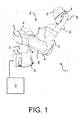
- the Fig. 1 shows a robot 1, in particular as a lightweight robot, which comprises a robot arm 2 and a control device 3.
- the robot arm 2 in the case of the present embodiment, a plurality of successively arranged and connected by means of joints 4 links 5.
- the robot arm 2 comprises a fastening device designed as a flange 6 for fastening a fastening device in the Fig. 2 closer illustrated tool 7.
- the links 5 may be relative to each other e.g. be moved with respect to axes of rotation A.
- the robot 1 also has not shown drives, which are preferably designed as electrical drives, in particular as a regulated electric drives. At least the electric motors of the electric drives, also not shown in detail, are arranged in or on the robot arm 2. Power electronics of the electric drives are e.g. within a housing of a control cabinet, not shown, within the e.g. also the control device 3 is arranged. At least parts of the power electronics can also be arranged in or on the robot arm 2.
- a Tool Center Point (TCP) 14 of the tool 7 automatically performs a predetermined movement, in particular one in the Fig. 3 shown workpiece 8 to edit.
- TCP Tool Center Point
- the control device 2 is intended to move the robot arm 2 by means of the computer program in such a way that the tool 7 or its tool center point 14 for processing the workpiece 8 has a predetermined path 9 from a starting point 9a of the web 8 to a End point 9b of the web 9 automatically departs.
- the machining of the workpiece 8 may be, for example, an adhesive or a welding process or a milling process.
- the computer program provided for controlling the movement of the robot arm 1 during the automatic program is assisted of the robot 1 and one in the Fig. 3 shown physical object 18 created.
- the physical object 18 comprises a surface 20 which is provided with a contour 19.
- the surface 20 is for example flat, as in the in the Fig. 3 the embodiment shown is the case.
- the surface 20 may also be curved or have at least one edge.
- the surface 20 of the physical object 18 is provided with a contour 19 whose course along the surface 20 is assigned to the course of the web 9 or corresponds to the course of the web 20.
- the contour 19 comprises a starting point 19a associated with the starting point 9a of the track 9 and an end point 19b associated with the end point 9b of the track 9.
- the contour 19 may be e.g. be designed as a recess 21 in the surface 20. However, the contour 19 may be e.g. also be executed as an increase on the surface 20.
- the contour 19, which is in the form of a depression 21, may be e.g. be made by milling.
- the physical object 18 may preferably have been produced by means of a 3D printer.
- the tool 7 is provided with a guide device 10 in the case of the present embodiment.
- the guide device 10 may be formed, for example, as a guide pin 11, as shown in the Fig. 2 is shown.
- the guide device 10 and the guide pin 11 and the workpiece 7 are at a known angle ⁇ , which is preferably 90 °, aligned with each other.
- ⁇ which is preferably 90 °, aligned with each other.
- the guide device 10 instead of the tool 7 for creating of the computer program is attached to the flange 6 of the robot arm 3.
- the guide device 10 also has a tool center point 15.
- the robot arm 2 is moved in particular by manual guidance such that the guide device 10, in particular the tip 11a of the guide pin 11 at the starting point 19a of the contour 19 or the recess 21 of the physical object 18th has arrived.
- Manual guiding is understood to mean that a person manually moves the robot arm 2 by pulling and / or pushing on its structure.
- the robot arm 2 comprises in particular force and / or moment sensors connected to the control device 3, which determine the forces or torques on the individual links 5.
- This makes it possible for the control device 3 to control the drives during manual guidance of the robot arm 2 in such a way that they at least support the movements of the individual links 5 that arise as a result of manual guidance.
- the person moves by manual guidance of the robot arm 2, the guide device 10 and the guide pin 11 along the contour 19 to the end point 19b of the contour 19.
- the control device 3 stores information about the position, possibly also about the orientation, which the guide device 11 or its tool center point 15 occupy during its movement along the contour 19. This information is recorded, for example, in discrete steps. This information can also be recorded by means of the corresponding positions of the axes A of the robot arm 2.
- the guide device 10 and the contour 19 or the guide pin 11 and the recess 21 are matched to each other, so that they preferably cooperate positively and / or non-positively.
- the guide device 10 can be improved along the contour 19 manually.
- the robot arm 3, controlled by the control device 2 automatically moves the guide device 10 along the contour 19 until the guide device 10 reaches the end point 19b.
- the contour 19 guides the guide device 10. The person leading the robot arm 3 manually can press the guide device 10 against the contour 19 at the starting point 19a of the contour 19 with a certain minimum force.
- the robot arm 3 can then automatically follow the contour 19 up to its end point 19b in order to obtain information about the position, if necessary also the orientation, of the guide device 11 or its tool center point 15 during its movement along the Contains contour 19 to save.
- the guide device 11 is fastened to the flange 6 of the robot arm 3, the recorded positions or positions of the axes A, possibly adjusted by scaling, already correspond to positions or positions of the tool center point 14 of the tool 7 or positions of the axes A during the automatic mode. If, however, the guide device 10 is attached to the tool 7, then it is the control device 3 due to the knowledge of the relative orientation of the guide device 10 relative to the tool 7 possible, the corresponding Positions, positions of the axes A to calculate. This can be done during the manual guidance of the robot arm 2 or during the automatic movement of the robot arm 2 or also after the completion of the corresponding movement of the robot arm 2.
- control device 2 receives the information about the positions or positions that the robot arm 3 or the tool 7 should assume during the automatic operation.
- This scale can e.g. already stored in the control device 3 or can be entered in this.
- this scaling or the determination of the scale takes place by starting, preferably by manually guiding the robot arm 2, by at least two pairs of mutually corresponding reference points 12, 22, 13, 23 of the workpiece 8 and of the object 18
- the reference points 12, 22, 13, 23 are, for example, the starting points 19a, 9a and the end points 19b, 9b of the contour 19 and the path 9.
- the scale can then be determined on the basis of the distances between the reference points of the object 18 and the workpiece 8.
- the tool 7 is moved by manually guiding the robot arm 2 to the starting point 9a of the web 9 and then the automatic operation of the robot 1 is started. If the position or position of the workpiece 8 is known, it is also possible for the robot arm 2, controlled by the control device 3, to automatically move the tool 7 toward the workpiece 8 in the course of the automatic mode, in order to subsequently machine it.
- the contour 19 can also run along a curved surface.
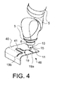
- the Fig. 4 shows a part of the robot arm 2 with its flange 6 and another physical object 48, which has a curved surface 40.
- This surface 40 is provided with the contour 19, which in the in the Fig. 4 shown embodiment as a recess or as a slot 41 in the surface 40 is executed.
- This physical object 48 is likewise provided for programming the robot 1, wherein the contour 19 is likewise assigned to a path which the robot 1 is to travel after programming in automatic mode.
- the physical object 48 has been e.g. produced by a 3D print.
- the recess or slot 41 may also have been made by milling into the surface 40.
- the guide device 10 can also be fastened to the flange 6 instead of the tool 7 provided for the machining of the workpiece 8.
- An example of such an embodiment is in Fig. 4 shown.
- the in the Fig. 4 Illustrated guide device 10 also includes the guide pin 11 or is executed as the guide pin 11, which is preferably moved for programming the robot 1 from the starting point 19a to the end point 19b of the contour 19 along the contour 19 designed as a slot 41 by manually guiding the robot arm 3.
- Trained as a guide pin 11 guide device 10 is adapted to the designed as a slot 41 contour 19, preferably adapted so that it cooperates positively with the slot 41.
- the position of the tool center point 15 of the guide device 10 or of the guide pin 11 corresponds to the position of the tool center point 14 of the tool 7, which is fastened to the flange 6 of the robot arm 3 during the automatic operation.
- the contact surfaces between the guiding device 10 formed as a guide pin 11 and the contour 19 formed as a slot 41 are preferably designed such that they cause as little friction as possible.
- the contour 19 can also be designed as an elevation on the surface of the physical object.
- An example of such an embodiment is in Fig. 5 which shows a physical object 58 with a surface 50 which, instead of the one shown in FIG Figures 3 and 4 shown physical objects 18, 48 can be used to program the robot 1.
- the surface 50 of the in the Fig. 5 shown physical object 58 is provided with an executed as an increase contour 19.
- the physical object 58 was preferably generated by means of a 3D print.
- the contour 19 designed as an increase may have been glued to the surface 50, for example, or likewise produced by 3D printing.
- the executed as an increase contour 19 is in the case of in the Fig. 5 1, along which the guide device 10 is moved by means of the robot 1 from the starting point 19a to the end point 19b of the programming contour 19, preferably by means of manual guiding.
- the guide device 10 is fastened to the flange 6 of the robot arm 2 during programming instead of the tool 7.
- the flange 6 facing away from the end 52 of the guide device 10 is designed such that it is able to engage positively in the running as a rail 51 contour 19.
- the contact surfaces between the guide device 10 and the guide device 10 formed as a rail 51 are preferably designed such that they cause as little friction as possible.
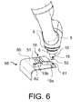
- FIG. 12 shows another alternative embodiment of a physical object 68 that may be used to program the robot 1 instead of the previously described physical objects 18, 48, 58.
- FIG. 6 shown physical object 68 differs from that in the Fig. 5 shown physical object 58 in that the running as a rail 51 contour 19 have physical switching structures, which are assigned to the starting point 19a and the end point 19b of the contour 19.
- the physical switching structure associated with the starting point 19a is designed as a cam 61, which is formed on the rail 51 at the starting point 19a.
- the associated with the end point 19b Physical switching structure is carried out in the case of the present embodiment as a notch 62, which is inserted into the rail 51 at the end point 19b.
- FIG. 12 shows another alternative embodiment of a physical object 78 which may be used to program the robot 1 instead of the previously described physical objects 18, 48, 58, 58.
- FIG. 7 shown physical object 78 differs from that in the Fig. 5 shown physical object 58 in that the designed as a rail 71 contour 19 has a cross-sectionally T-shaped profile and that the flange 6 remote from the end 72 of the guide device 10 is designed such that it surrounds the T-shaped end of the guide rail 71 able to encompass in particular positive and / or non-positive. This ensures that the guide device 10 is movable only along the rail 71. This possibly facilitates not only the manual guiding but also an automatic movement of the guide device 10 along the rail 71 by means of the robot 1 or the robot arm 2.
- the rail 71 may also be provided with the physical switching structures.
Landscapes
- Engineering & Computer Science (AREA)
- Robotics (AREA)
- Mechanical Engineering (AREA)
- Physics & Mathematics (AREA)
- General Physics & Mathematics (AREA)
- Automation & Control Theory (AREA)
- Manipulator (AREA)
Applications Claiming Priority (1)
| Application Number | Priority Date | Filing Date | Title |
|---|---|---|---|
| DE102014204475.8A DE102014204475A1 (de) | 2014-03-11 | 2014-03-11 | Verfahren zum Betreiben eines Roboters |
Publications (2)
| Publication Number | Publication Date |
|---|---|
| EP2919085A2 true EP2919085A2 (fr) | 2015-09-16 |
| EP2919085A3 EP2919085A3 (fr) | 2016-06-29 |
Family
ID=52810937
Family Applications (1)
| Application Number | Title | Priority Date | Filing Date |
|---|---|---|---|
| EP15158379.6A Withdrawn EP2919085A3 (fr) | 2014-03-11 | 2015-03-10 | Procédé de fonctionnement d'un robot |
Country Status (2)
| Country | Link |
|---|---|
| EP (1) | EP2919085A3 (fr) |
| DE (1) | DE102014204475A1 (fr) |
Family Cites Families (10)
| Publication number | Priority date | Publication date | Assignee | Title |
|---|---|---|---|---|
| JP2783456B2 (ja) * | 1990-11-16 | 1998-08-06 | ファナック株式会社 | ロボットの座標系設定方式 |
| US5297238A (en) * | 1991-08-30 | 1994-03-22 | Cimetrix Incorporated | Robot end-effector terminal control frame (TCF) calibration method and device |
| US5495410A (en) * | 1994-08-12 | 1996-02-27 | Minnesota Mining And Manufacturing Company | Lead-through robot programming system |
| DE19913756A1 (de) * | 1999-03-26 | 2000-09-28 | Audi Ag | Vorrichtung zum Teachen eines programmgesteuerten Roboters |
| US6385508B1 (en) * | 2000-10-31 | 2002-05-07 | Fanuc Robotics North America, Inc. | Lead-through teach handle assembly and method of teaching a robot assembly |
| DE102004026813A1 (de) * | 2004-06-02 | 2005-12-29 | Kuka Roboter Gmbh | Verfahren und Vorrichtung zum Steuern von Handhabungsgeräten |
| GB0917309D0 (en) * | 2009-10-02 | 2009-11-18 | Twi Ltd | Method and system of programming a robot |
| DE102010029745A1 (de) * | 2010-06-07 | 2011-12-08 | Kuka Laboratories Gmbh | Werkstück-Handhabungssystem und Verfahren zum Manipulieren von Werkstücken mittels kooperierender Manipulatoren |
| US8805581B2 (en) * | 2012-02-21 | 2014-08-12 | GM Global Technology Operations LLC | Procedural memory learning and robot control |
| US8843236B2 (en) * | 2012-03-15 | 2014-09-23 | GM Global Technology Operations LLC | Method and system for training a robot using human-assisted task demonstration |
-
2014
- 2014-03-11 DE DE102014204475.8A patent/DE102014204475A1/de not_active Ceased
-
2015
- 2015-03-10 EP EP15158379.6A patent/EP2919085A3/fr not_active Withdrawn
Non-Patent Citations (1)
| Title |
|---|
| None |
Also Published As
| Publication number | Publication date |
|---|---|
| EP2919085A3 (fr) | 2016-06-29 |
| DE102014204475A1 (de) | 2015-09-17 |
Similar Documents
| Publication | Publication Date | Title |
|---|---|---|
| DE69220409T2 (de) | Werkzeugsteueranlage bestehend aus einer Schweisszange zur Durchführung von bestimmten Arbeiten an Werkstücken und aus einem automatischen Positionierungsystem zur Steuerung der relativen Bewegung der Schweisszange in Beziehung zu diesem Werkstück | |
| EP2883665B1 (fr) | Procédé et dispositif destinés à la commande d'un manipulateur | |
| DE102007026299B4 (de) | Industrieroboter und Verfahren zum Programmieren eines Industrieroboters | |
| EP1950010B1 (fr) | Robot et procédé de programmation d'un robot | |
| DE102008041602B4 (de) | Roboter und Verfahren zum Steuern eines Roboters | |
| EP2631040B1 (fr) | Station de traitement et procédé de fonctionnement d'une telle station | |
| EP2851162B1 (fr) | Procédé de réglage manuel de la pose d'un bras manipulateur d'un robot industriel et robot industriel associé | |
| DE2624012A1 (de) | Verfahren und vorrichtung zur programmierung | |
| DE102013013114A1 (de) | Vorrichtung zum automatisierten Entnehmen von in einem Behälter angeordneten Werkstücken | |
| DE102018007842B4 (de) | Steuergerät zum Überwachen der Bewegungsrichtung eines Betätigungswerkzeugs | |
| WO2009080526A1 (fr) | Robot industriel et procédé de programmation d'un robot industriel | |
| EP3362229A1 (fr) | Référencement haptique d'un manipulateur | |
| EP3131710A1 (fr) | Dispositif robot présentant un axe linéaire | |
| DE202012007288U1 (de) | Transportvorrichtung zum umlaufenden Transportieren von Objekten | |
| DE112018005783T5 (de) | Hauptform- und Kernverbindungsvorrichtung und Hauptform- und Kernverbindungsverfahren | |
| DE102016111521A1 (de) | Vorrichtung zum Herstellen eines Kabelbaums | |
| DE102007029398A1 (de) | Verfahren und Vorrichtung zum Programmieren eines Industrieroboters | |
| DE102007062109A1 (de) | Industrieroboter und Verfahren zum Steuern eines Industrieroboters | |
| EP3117280A2 (fr) | Procédé pour faire fonctionner un robot et robot correspondant équipé d'un dispositif palpeur mécanique | |
| EP2431114A2 (fr) | Tour doté d'une broche de guidage et de traction et d'une commande électronique pour le coulisseau longitudinal et/ou transversal | |
| EP2504741B1 (fr) | Procédé d'élaboration d'un modèle de robot, et robot industriel | |
| DE19943318A1 (de) | Verfahren und Vorrichtung zum Erfassen der Position von Bahnpunkten einer Trajektorie | |
| EP2919085A2 (fr) | Procédé de fonctionnement d'un robot | |
| EP2334470A1 (fr) | Dispositif de travail avec une unité de détection et une unité de travail | |
| DE102006051835B4 (de) | Schalungsroboteranordnung zur Herstellung von Betonfertigteilen |
Legal Events
| Date | Code | Title | Description |
|---|---|---|---|
| PUAI | Public reference made under article 153(3) epc to a published international application that has entered the european phase |
Free format text: ORIGINAL CODE: 0009012 |
|
| AK | Designated contracting states |
Kind code of ref document: A2 Designated state(s): AL AT BE BG CH CY CZ DE DK EE ES FI FR GB GR HR HU IE IS IT LI LT LU LV MC MK MT NL NO PL PT RO RS SE SI SK SM TR |
|
| AX | Request for extension of the european patent |
Extension state: BA ME |
|
| RIN1 | Information on inventor provided before grant (corrected) |
Inventor name: NEUREITER, REINHARD Inventor name: HONSBERG, OTMAR Inventor name: STOCKSCHLAEDER, JULIAN Inventor name: ZUNKE, RICHARD |
|
| PUAL | Search report despatched |
Free format text: ORIGINAL CODE: 0009013 |
|
| AK | Designated contracting states |
Kind code of ref document: A3 Designated state(s): AL AT BE BG CH CY CZ DE DK EE ES FI FR GB GR HR HU IE IS IT LI LT LU LV MC MK MT NL NO PL PT RO RS SE SI SK SM TR |
|
| AX | Request for extension of the european patent |
Extension state: BA ME |
|
| RIC1 | Information provided on ipc code assigned before grant |
Ipc: B25J 9/16 20060101ALI20160520BHEP Ipc: G05B 19/423 20060101AFI20160520BHEP |
|
| STAA | Information on the status of an ep patent application or granted ep patent |
Free format text: STATUS: REQUEST FOR EXAMINATION WAS MADE |
|
| 17P | Request for examination filed |
Effective date: 20161227 |
|
| RBV | Designated contracting states (corrected) |
Designated state(s): AL AT BE BG CH CY CZ DE DK EE ES FI FR GB GR HR HU IE IS IT LI LT LU LV MC MK MT NL NO PL PT RO RS SE SI SK SM TR |
|
| STAA | Information on the status of an ep patent application or granted ep patent |
Free format text: STATUS: THE APPLICATION IS DEEMED TO BE WITHDRAWN |
|
| 18D | Application deemed to be withdrawn |
Effective date: 20201001 |
|
| P01 | Opt-out of the competence of the unified patent court (upc) registered |
Effective date: 20230528 |