EP2919329B1 - Steckverbinder - Google Patents
Steckverbinder Download PDFInfo
- Publication number
- EP2919329B1 EP2919329B1 EP15156652.8A EP15156652A EP2919329B1 EP 2919329 B1 EP2919329 B1 EP 2919329B1 EP 15156652 A EP15156652 A EP 15156652A EP 2919329 B1 EP2919329 B1 EP 2919329B1
- Authority
- EP
- European Patent Office
- Prior art keywords
- metal member
- contact
- face
- portions
- connector
- Prior art date
- Legal status (The legal status is an assumption and is not a legal conclusion. Google has not performed a legal analysis and makes no representation as to the accuracy of the status listed.)
- Not-in-force
Links
- 239000002184 metal Substances 0.000 claims description 95
- 230000000452 restraining effect Effects 0.000 description 10
- 238000005452 bending Methods 0.000 description 8
- 208000032365 Electromagnetic interference Diseases 0.000 description 7
- 238000006073 displacement reaction Methods 0.000 description 5
- 230000005489 elastic deformation Effects 0.000 description 4
- 238000000034 method Methods 0.000 description 3
- 230000000717 retained effect Effects 0.000 description 3
- 238000010276 construction Methods 0.000 description 2
- 238000003780 insertion Methods 0.000 description 2
- 230000037431 insertion Effects 0.000 description 2
- 230000005540 biological transmission Effects 0.000 description 1
- 230000006835 compression Effects 0.000 description 1
- 238000007906 compression Methods 0.000 description 1
- 239000004020 conductor Substances 0.000 description 1
- 238000005260 corrosion Methods 0.000 description 1
- 230000007797 corrosion Effects 0.000 description 1
- 230000000694 effects Effects 0.000 description 1
- 239000011810 insulating material Substances 0.000 description 1
- 238000012986 modification Methods 0.000 description 1
- 230000004048 modification Effects 0.000 description 1
- 239000011347 resin Substances 0.000 description 1
- 229920005989 resin Polymers 0.000 description 1
- 239000000758 substrate Substances 0.000 description 1
Images


Classifications
-
- H—ELECTRICITY
- H01—ELECTRIC ELEMENTS
- H01R—ELECTRICALLY-CONDUCTIVE CONNECTIONS; STRUCTURAL ASSOCIATIONS OF A PLURALITY OF MUTUALLY-INSULATED ELECTRICAL CONNECTING ELEMENTS; COUPLING DEVICES; CURRENT COLLECTORS
- H01R13/00—Details of coupling devices of the kinds covered by groups H01R12/70 or H01R24/00 - H01R33/00
- H01R13/648—Protective earth or shield arrangements on coupling devices, e.g. anti-static shielding
- H01R13/658—High frequency shielding arrangements, e.g. against EMI [Electro-Magnetic Interference] or EMP [Electro-Magnetic Pulse]
- H01R13/6581—Shield structure
-
- H—ELECTRICITY
- H01—ELECTRIC ELEMENTS
- H01R—ELECTRICALLY-CONDUCTIVE CONNECTIONS; STRUCTURAL ASSOCIATIONS OF A PLURALITY OF MUTUALLY-INSULATED ELECTRICAL CONNECTING ELEMENTS; COUPLING DEVICES; CURRENT COLLECTORS
- H01R13/00—Details of coupling devices of the kinds covered by groups H01R12/70 or H01R24/00 - H01R33/00
- H01R13/46—Bases; Cases
- H01R13/502—Bases; Cases composed of different pieces
- H01R13/506—Bases; Cases composed of different pieces assembled by snap action of the parts
-
- H—ELECTRICITY
- H01—ELECTRIC ELEMENTS
- H01R—ELECTRICALLY-CONDUCTIVE CONNECTIONS; STRUCTURAL ASSOCIATIONS OF A PLURALITY OF MUTUALLY-INSULATED ELECTRICAL CONNECTING ELEMENTS; COUPLING DEVICES; CURRENT COLLECTORS
- H01R13/00—Details of coupling devices of the kinds covered by groups H01R12/70 or H01R24/00 - H01R33/00
- H01R13/648—Protective earth or shield arrangements on coupling devices, e.g. anti-static shielding
- H01R13/658—High frequency shielding arrangements, e.g. against EMI [Electro-Magnetic Interference] or EMP [Electro-Magnetic Pulse]
- H01R13/6591—Specific features or arrangements of connection of shield to conductive members
- H01R13/6594—Specific features or arrangements of connection of shield to conductive members the shield being mounted on a PCB and connected to conductive members
-
- H—ELECTRICITY
- H01—ELECTRIC ELEMENTS
- H01R—ELECTRICALLY-CONDUCTIVE CONNECTIONS; STRUCTURAL ASSOCIATIONS OF A PLURALITY OF MUTUALLY-INSULATED ELECTRICAL CONNECTING ELEMENTS; COUPLING DEVICES; CURRENT COLLECTORS
- H01R12/00—Structural associations of a plurality of mutually-insulated electrical connecting elements, specially adapted for printed circuits, e.g. printed circuit boards [PCB], flat or ribbon cables, or like generally planar structures, e.g. terminal strips, terminal blocks; Coupling devices specially adapted for printed circuits, flat or ribbon cables, or like generally planar structures; Terminals specially adapted for contact with, or insertion into, printed circuits, flat or ribbon cables, or like generally planar structures
- H01R12/70—Coupling devices
- H01R12/71—Coupling devices for rigid printing circuits or like structures
- H01R12/72—Coupling devices for rigid printing circuits or like structures coupling with the edge of the rigid printed circuits or like structures
- H01R12/722—Coupling devices for rigid printing circuits or like structures coupling with the edge of the rigid printed circuits or like structures coupling devices mounted on the edge of the printed circuits
- H01R12/724—Coupling devices for rigid printing circuits or like structures coupling with the edge of the rigid printed circuits or like structures coupling devices mounted on the edge of the printed circuits containing contact members forming a right angle
Definitions
- This disclosure relates to a connector to be electrically connected to a connecting object, the connector having a plurality of metal shells.
- This connector includes a contact, a first insulating member (an inner housing) holding the contact, a first metal member (an inner shell) covering the first insulating member, a second insulating member (an outer housing) disposed outside the first metal member, and a second metal member (an outer shell) covering the second insulating member.
- Japanese Unexamined Patent Application Publication No. 2009-70752 further discloses a technique for enhancement of shielding performance in which a leading end of a contact piece formed by inward bending of a portion of the second metal member is placed in contact with the first metal member in a direction perpendicular to a connecting direction of the connecting object.
- As contact between the first metal member and the second metal member is formed on the connector side need for forming such electric connection therebetween on the circuit board side side can be eliminated, thus allowing higher degree of designing freedom for the circuit board.
- JP H08 306435 A discloses an electrical connector that is mounted on a wiring substrate.
- US 2010/0003852 A1 discloses a shielded electrical connector that includes a receptacle having an outer ground shield surrounding a dielectric cover.
- JP 2006 310164 A discloses a connector
- US 2013/059472 A1 discloses a shielded connector according to the preamble of independent claim 1.
- the contact between the leading end of the contact piece of the second metal member and the first metal member is a line contact having limited contact area, so that there remains room for improvement for the purpose of EMI characteristics improvement contemplated.
- the contact between the first metal member and the second metal member is formed along the direction perpendicular to the connecting direction of the connecting object, it is difficult for a pressing force applied to the connecting object to be reflected in its contact force.
- contact failure tends to occur between the first metal member and the second contact member in the event of e.g. development of corrosion in the metal member(s) due to moisture or application of a strong vibration thereto along the perpendicular direction, so that a desired shielding effect may not be obtained.
- a connector having a double shielded construction which connector, though simple in its configuration, can improve the EMI characteristics reliably.
- the connector comprises:
- a bulging portion which bulges outwards from the outer face of the first metal member covered by the second metal member, this bulging portion comes into contact with an inner face of the second metal member.
- the shape of the bulging portion can be set as desired. For instance, through e.g. increase in the contact area between the first metal member and the second metal member or adjustment of the thickness of the bulging portion for ensuring desired force of contact, reliable contact between the first metal member and the second metal member is made possible.
- the bulging portion is formed in its outer face on the side of the rear end portion opposed to the front end portion to which the connecting object is to be connected. Accordingly, the direction of contact of the first metal member via its bulging portion with the second metal member is in agreement with the direction of connecting the connecting object to the connector. That is, a pressing force used for establishing connection of the connecting object to the first insulating member is transmitted via this first insulating member to the first metal member and also to the second metal member contacting the first metal member. Therefore, this pressing force serves as a compression force for providing elastic deformation of the bulging portion of the first metal member, so that firm contact can be formed between the first metal member and the second metal member.
- the bulging portion is provided in the form of a face.
- bulging portion is provided in the form of a face as proposed in the above embodiment, face contact is formed between the first metal member and the second metal member, thus realizing increased contact area therebetween and even further improvement in the EMI characteristics.
- the second insulating member includes a groove formed in a direction perpendicular to a connecting direction of the connecting object; and the second metal member includes an inwardly projecting portion which is fitted within the groove.
- the second metal member along the direction perpendicular to the connecting direction of the connecting object, the second metal member will be attached to the second insulating member. Namely, the projecting portion of the second metal member will be guided along the groove of the second insulating member.
- firm contact can be realized between the first metal member and the second metal member.
- positional error will hardly occur in association with insertion/withdrawal of the connecting object. Therefore, the contact between the first metal member and the second metal member can be maintained for a long period of time.
- an abutment portion which abuts the second insulating member while being bound between the second insulating member and the second metal member, movement of the first metal member toward the front end portion is prevented by abutment of the abutment portion to the second insulating member.
- the abutment portion abutting the second insulating member prevents movement of the first metal member toward the front end portion. Therefore, inside the connector, the first metal member is bound between the second insulating member and the second metal member without positional error or displacement, so that inadvertent variation in the relative position will hardly occur between the first metal member and the second metal member, thus ensuring reliable contact therebetween.
- the second insulating member is fitted over the first metal member along the connecting direction of the connecting object; and the abutment portion extends outwards from the rear end portion of the first metal member.
- the configuration since the abutment portion extends outwards from the rear end portion of the first metal member, the configuration requires only bending of an end of the first metal member. Thus, compared with an arrangement of providing a retaining member separately, the above configuration allows reduction in the number of assembly steps and costs. Further, when the second insulating member is fitted over the first metal member along the connecting direction of the connecting object, the abutment portion of the first metal member comes into contact with the second insulating member, thus being fixedly positioned relative thereto. Therefore, the assembly can be facilitated.
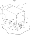
- Fig. 1 is an upper perspective view of the connector C in the instant embodiment.
- Figs. 2 and 3 are an exploded perspective view showing the connector C as seen from its rear upper side and an exploded perspective view showing the connector C as seen from its front lower side.
- Fig. 4 is a partially exploded perspective view showing the connector C as seen from its rear upper side
- Fig. 5 is a side view in section showing the connector C
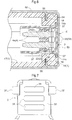
- Fig. 6 is a section view showing the connector C as seen in a direction VI-VI in Fig. 5 .
- the side of the connector C which side is connected to the circuit board K will be defined as the lower side, and the opposite side thereto will be defined as the upper side, respectively.
- the side thereof to which the connecting object is to be connected will be defined as the front side and the opposite side thereto will be defined as the rear side, respectively.
- the connector C includes the contacts 4 to be electrically connected to the connecting object, a second body 2 (an example of “first insulating member") holding the contacts 4, an inner shell 3 (an example of “first metal member”) covering the second body 2, a first body 1 (an example of “second insulating member”) holding the inner shell 3, and an outer shell 5 (an example of "second metal member”) covering the first body 1 and the inner side shell 3.
- the second body 2 includes a front end portion 25 to which the connecting object is connected and a rear end portion 26 opposed (opposite) to this front end portion 25.
- the first body 1 and the second body 2 are formed of an insulating material such as resin
- the contacts 4 and the outer shell 5 are formed of a conductive material such as metal.
- the first body 1 is provided in the form of a tubular (hollow) body and includes a connected portion 11 to which the connecting object is to be connected and a covered portion 12 covered by the outer shell 5.
- a connected portion 11 to which the connecting object is to be connected
- a covered portion 12 covered by the outer shell 5.
- a first opening 13a into which the connecting object is to be inserted.
- a second opening portion 14a into which the second body 2 and the inner shell 3 are to be inserted.
- curved face portions 12a are provided at the opposed lateral ends of the upper face of the covered portion.
- the second opening portion 14a has its right and left opposed end portions formed concave, thus forming restraining portions 14c for preventing forward movement of the inner shell 3 by the abutment thereto when this inner shell 3 is inserted.
- the upper face of the covered portion 12 is formed lower than the upper face of the connected portion 1. Also, the covered portion 12 has lateral walls 17 on the opposed sides and in each of these opposed lateral walls 17, there are formed a first concave portion 17a, a second concave portion 17b and a groove 18 in this mentioned order from the front side.
- the concave portions 17a, 17b are formed at two portions by cutting away the lower end of the lateral wall 17 by a predetermined width. Further, at the upper ends of the concave portions 17a, 17b, there are provided restraining faces 17c for restraining upward displacement of the outer shell 5.
- the groove 18 is formed by cutting away the lateral wall 17 vertically elongate, from the curved face portion 12a to an intermediate position of the lateral wall 17.
- guide grooves 22 acting as guides when the inner shell 3 is inserted from the front side.
- a rear end portion 26 to which a cover portion 32 of the inner shell 3 comes into contact and a concave portion 21 is formed from the rear end portion 26 downwards.
- contact holes 23 and retaining grooves 24 for fixing the contacts 4.
- the front end portion 25 of the second body 2 is formed in the form of a stepped-down portion, thus providing an abutment portion 27 to which the first body 1 abuts.
- the contact holes 23 are formed through vicinity of the center of the front end face of the concave portion 21 to the front side of the second body 2. Further, inside the concave portion 21, retaining grooves 24 for holding the contacts 4 are provided in the form of vertically elongate grooves.
- Each contact 4 includes a contacting portion 4a to come into contact with a terminal of the connecting object and an inserting portion 4b to be inserted into the circuit board K.
- the inserting portion 4b is formed by bending so as to extend downwards from the rear end of the contacting portion 4a. The contact 4 will be held by the second body 2 with pressing of the contacting portion 4a into the contact hole 23 from the rear side of the second body 2 and fitting of the upper portion of the inserting portion 4b into the retaining groove 24.
- the inner shell 3 includes a tubular portion 31, a cover portion 32 extending rearwards from the tubular portion 31, a bending portion 32 for bending the cover portion 32, and leg portions 34 extending downwards from the tubular portion 31.
- the cover portion 32 includes rib portions 35 (an example of “bulging portions”) bulging outwards (rearwards) from the outer face thereof to come into contact with the inner face of the rear side of the outer shell 5.
- the rib portions 35 in the form of vertically elongate faces are provided on the right and left opposed sides of the cover portion 32.
- face contact is formed between these rib portions 35 and the inner face of the outer shell 5, that is, as the inner shell 3 and the outer shell 5 are in contact over a large area with each other, high-frequency wave transmission characteristics is improved.
- the circuit board K since there is no need for the circuit board K to provide wiring to realize the connection between the inner shell 3 and the outer shell 5, there is obtained higher freedom in pattern designing of the circuit board K.
- guiding projections 38 On the inner face of the lateral walls of the tubular portion 31, there are formed guiding projections 38 extending inwards to come into contact with the guide grooves 22 of the second body 2.
- the inner shell 3 will be inserted from the front side of the second body 2, with engagement between the guide grooves 22 and the guiding projections 38.
- bulging portions 36 which bulge outwards.
- abutment portions 37 are formed to extend outwards to abut the restraining portions 14c provided in the second opening portion 14a of the first body 1. With this, forward movement of the inner shell 3 inside the connector C is prevented.
- the leg portions 34 extend downwards from the opposed side ends of the cover portion 32 to be inserted into the holes provided in the circuit board K.
- the inner shell 3 under the conditions illustrated in Fig. 2 and Fig. 3 , is formed approximately at a right angle relative respectively to the upper face of the tubular portion 31 and the rear face of the cover portion 32; but prior to its attachment to the second body 2, the upper face of the tubular portion 31 and the upper face of the cover portion 32 are located on a same plane (the condition denoted with two-dotted lines).
- the cover portion 32 will be bent downwards at its bent portion 33 after engagement of the second body 2 having the contacts 4 pressed therein from the rear side of the inner shell 3. With this, as shown in Fig. 5 , contact is established between the rear end portion 26 of the second body 2 and the inner face of the cover portion 32 of the inner shell 3.
- the outer shell 5 is fitted over the covered portion 12 of the first body 1 from above.
- the outer shell 5 includes an upper face portion 51 covering the upper face of the covered portion 12, lateral walls 52 covering the lateral walls 17 of the covered portion 12, and a rear face portion 53 covering the rear face of the inner shell 3.
- the lateral walls 52 of the outer shell 5 extend downwards from the opposed lateral ends of the upper face portion 51 of the outer shell 5.
- the upper face portion 51 and the lateral walls 52 are formed by bending a single metal plate.
- the opposed lateral ends of the upper face portion 51 have curved shapes to follow the contour of the curved face portions 12a of the first body 1.
- the projecting pieces 52a, 52c are formed to extend from the lower end of the lateral wall 52 of the outer shell 5. After the outer shell 5 is fitted over the first body 1, the projecting pieces 52a, 52c are bent to be engaged with the concave portions 17a, 17b and fixed therein. In this, by the restraining faces 17c at the upper ends of the concave portions 17a, 17b, upward displacement of the outer shell 5 is restrained.
- the leg portions 52b, 52d are formed to extend downwards from the lower ends of the lateral walls 52 to be inserted into the holes provided in the circuit board K.
- the fixing portion 52e is provided downwardly of the rear end portion of the lateral wall 52 and formed as an inwardly projecting projection.
- the rear face portion 53 of the outer shell 5 is formed to extend downwards from the rear end of the upper face portion 51. Further, the rear face portion 53 is formed by the same single metal plate forming the upper face portion 51 and the lateral walls 52 and the rear face portion 53 is formed by being bent downwards at the rear end of the upper face portion 51. Further, as shown in Fig. 3 , the rear face portion 53 includes lateral portions 54, projecting portions 55, and third leg portions 53a. In this embodiment, as shown in Fig. 6 , when the outer shell 5 is fitted over the first body 1, the inner face of the rear face portion 53 comes into face-contact with the rib portions 35 of the inner shell 3.
- the lateral portions 54 are formed by being bent to extend forwardly from the opposed lateral ends of the rear face portion 53. Further, at lower portions of the lateral portions 54, fixed portions 54a to be fixed to the fixing portions 52e of the lateral walls 52 are provided in the form of through holes. In these through holes, the aforementioned projections provided in the lateral walls 52 of the outer shell 5 will be inserted, thus fixedly retaining the lateral walls 52 and the rear face portion 53 to each other.
- each projecting portion 55 is formed to extend inwards from upper portions of the front end portions of the lateral walls 54.
- each projecting portion 55 is formed as a plate-like projecting piece and is formed by being bent at the front end of the lateral wall 54.
- the projecting portions 55 will be guided by the aforementioned grooves 18 of the first body 1.
- the third leg portions 53a extend from the lower ends of the vicinity of the opposed lateral ends of the rear face portion 53 to be inserted into the holes provided in the circuit board K, like the leg portions 52b, 52d.
- the inner shell 3 is fitted over the second body 2. Then, the second body 2 and the inner shell 3 assembled together are inserted to the second opening portion 14a of the first body 1.
- the rear face of the inner shell 3 is disposed on the same plane as the rear face of the first body 1.
- the abutment portions 37 of the inner shell 3 abut the restraining portions 14c of the first body 1 and also the abutment portion 27 of the second body 2 abuts the first body 1. With these, movement of the second body 2 and the inner shell 3 to the front side is restrained.
- the inserting portions 4b of the contacts 4 and the leg portions 34 of the inner shell 3 extend downwards beyond the lower face of the connector C through the cutouts 14b of the first body 1. Further, on the lower face of the first body 1, there are provided the bottom face projections 19 projecting downwards. These are inserted into the holes provided in the circuit board K. With these, the first body 1 is fixed in position relative to the circuit board K; and the first body 1, the inner shell 3 and the contacts 4 are connected to the circuit board K.
- the outer shell 5 is fitted from above over the covered portion 12 of the first body 1.
- the projecting portions 55 of the outer shell 5 engage into the grooves 18.
- the grooves 18 are formed along the direction perpendicular to the connecting direction of the connecting object. Therefore, even when the connecting object is inserted or withdrawn, the projecting portions 55 of the outer shell 5 come into contact with the inner faces of the grooves 18. Consequently, displacement of the outer shell 3 in the front/rear direction can be effectively prevented.
- each projecting portion 55 is provided in the form of a plate-like projecting piece which comes into face-contact with the inner face of the groove 18, the outer shell 5 and the first body 1 can be fixed even firmly to each other. Therefore, inadvertent withdrawal/removal of the outer shell 5 from the first body 1 can be prevented.
- the lateral portion 54 extends from the lateral end of the rear face 53 of the outer shell 5 and the projecting portion 55 projects from this lateral portion 54. Therefore, even when a force is applied to the projecting portion 55 in association with insertion/withdrawal of the connecting object, this force can be dissipated to the lateral portions 54 and the rear face portion 53 of the outer shell 5. Accordingly, thanks to high strength of the projecting portions 55, inadvertent withdrawal/removal of the outer shell 5 from the first body 1 can be effectively prevented. Incidentally, since the lateral portions 54 of the outer shell 5 are fixedly retained to the lateral walls 52 of the outer shell 5, the rear face portion 53 and the lateral walls 52 of the outer shell 5 are fixed to each other.
- the leg portions 52b, 52d, 53a of the outer shell 5 are inserted into the holes provided in the circuit board K. With this, the circuit board K and the outer shell 5 can be fixed to each other.
- the rear end portion 26 of the second body 2 comes into contact with the inner face of the cover portion 32 of the inner shell 3 and also the abutment portion 27 of the front end portion 25 of the second body 2 abuts the first body 1. Further, as shown in Fig. 6 , the abutment portions 37 of the inner shell 3 abut the restraining portions 14c of the first body 1, and the rib portions 35 formed on the outer face of the cover portion 32 of the inner shell 3 come into contact with the inner face of the rear face portion 53 of the outer shell 5.
- the second body 2 and the inner shell 3 are fixed in position relative to the first body 1 and the outer shell 5, thus preventing forward movement of the inner shell 3. Accordingly, even when the main body is comprised of a plurality of components, there is no need to provide any additional member for fixing these main body components to each other. Thus, the configuration can be made simple.
- the outer shell 5 when the outer shell 5 is to be fitted over the first body 1, as the rib portions 35 are provided on the outer side of the cover portion 32 of the inner shell 3, the rear face portion 53 is elastically deformed to the outer side (rear side). As a result, strong face contact is established between the rib portions 35 of the inner shell 3 and the rear face portion 53 of the outer shell 5, thus improving the EMI characteristics. Further, the pressing force used for connecting the connecting object to the second body 2 is transmitted via the rear end portion 26 of the second body 2 to the inner shell 3 and then to the outer shell 5. Therefore, a compressive force will be applied to cause elastic deformation of the rib portions 35 of the inner shell 3, whereby the rib portions 35 and the rear face 53 can be placed into firm contact with each other.
- the rib portions 35 extend in the direction perpendicular to the connecting direction of the connecting object, the pressing force applied to the connecting object is transmitted and also contact failure will hardly occur even in the event of vibration in the vertical direction.
- the rib portion 35 has its height, position and size adjusted such that the rib portion 35 can cause elastic deformation of the rear face portion 53 of the outer shell 5 and can also ensure reliable contact between the inner shell 3 and the outer shell 5.
Landscapes
- Details Of Connecting Devices For Male And Female Coupling (AREA)
- Connector Housings Or Holding Contact Members (AREA)
- Coupling Device And Connection With Printed Circuit (AREA)
Claims (5)
- Steckverbinder (C), umfassend:einen Kontakt (4), der mit einem Verbindungsgegenstand elektrisch zu verbinden ist;ein erstes isolierendes Element (2), das einen vorderen Endteil (25), mit dem der Verbindungsgegenstand verbunden wird, und einen hinteren Endteil (26) hat, der dem vorderen Endteil (25) entgegengesetzt ist, wobei das erste isolierende Element (2) den Kontakt (4) hält;ein erstes Metallelement (3), welches das erste isolierende Element (2) abdeckt;ein zweites isolierendes Element (1), welches das erste Metallelement (3) hält;ein zweites Metallelement (5), welches das erste Metallelement (3) und das zweite isolierende Element (1) abdeckt; undwobei das erste Metallelement (3) einen vorgewölbten Teil (35) ausbildet, der von einer Rückfläche des ersten Metallelements (3) nach außen vorgewölbt ist,dadurch gekennzeichnet, dass der vorgewölbte Teil (35) mit einer Innenfläche eines hinteren Flächenteils (53) des zweiten Metallelements (5) in Kontakt ist, sodass der hintere Flächenteil (53) elastisch nach außen verformt wird, wenn das zweite Metallelement (5) über das zweite isolierende Element (1) gestülpt wird.
- Steckverbinder (C) gemäß Anspruch 1, wobei der vorgewölbte Teil (35) in der Form einer Fläche vorgesehen ist.
- Steckverbinder (C) gemäß Anspruch 1 oder 2, wobei:das zweite isolierende Element (1) eine Rille (18) aufweist, die in einer Richtung senkrecht zu einer Verbindungsrichtung des Verbindungsgegenstands ausgebildet ist; unddas zweite Metallelement (5) einen nach innen vorstehenden Teil (55) aufweist, der in die Rille (18) passt.
- Steckverbinder (C) gemäß einem der Ansprüche 1 bis 3, wobei:an dem hinteren Endteil (26) des ersten Metallelements (3) ein Stoßteil (37) ausgebildet ist, der gegen das zweite isolierende Element (1) stößt, während er zwischen das zweite isolierende Element (1) und das zweite Metallelement (5) eingebunden ist;eine Bewegung des ersten Metallelements (3) zum vorderen Endteil (25) hin durch ein Anstoßen des Stoßteils (37) an das zweite isolierende Element (1) verhindert wird.
- Steckverbinder (C) gemäß Anspruch 4, wobei:das zweite isolierende Element (1) entlang einer Verbindungsrichtung des Verbindungsgegenstands über das erste Metallelement (3) geschoben wird; undder Stoßteil (37) sich von dem hinteren Endteil (26) des ersten Metallelements (3) nach außen erstreckt.
Applications Claiming Priority (1)
| Application Number | Priority Date | Filing Date | Title |
|---|---|---|---|
| JP2014050120A JP2015176657A (ja) | 2014-03-13 | 2014-03-13 | コネクタ |
Publications (2)
| Publication Number | Publication Date |
|---|---|
| EP2919329A1 EP2919329A1 (de) | 2015-09-16 |
| EP2919329B1 true EP2919329B1 (de) | 2018-06-27 |
Family
ID=52577744
Family Applications (1)
| Application Number | Title | Priority Date | Filing Date |
|---|---|---|---|
| EP15156652.8A Not-in-force EP2919329B1 (de) | 2014-03-13 | 2015-02-26 | Steckverbinder |
Country Status (4)
| Country | Link |
|---|---|
| US (1) | US9401567B2 (de) |
| EP (1) | EP2919329B1 (de) |
| JP (1) | JP2015176657A (de) |
| CN (1) | CN104916995B (de) |
Families Citing this family (18)
| Publication number | Priority date | Publication date | Assignee | Title |
|---|---|---|---|---|
| JP6078919B2 (ja) * | 2013-07-18 | 2017-02-15 | ホシデン株式会社 | コネクタ |
| KR102283147B1 (ko) * | 2015-05-07 | 2021-07-30 | 삼성전자주식회사 | 전자 장치용 커넥터 및 그 전자 장치 |
| US10283915B2 (en) * | 2015-05-07 | 2019-05-07 | Samsung Electronics Co., Ltd | Connector and electronic device including the same |
| JP2017045604A (ja) * | 2015-08-26 | 2017-03-02 | タイコエレクトロニクスジャパン合同会社 | シールドコネクタ |
| US9425558B1 (en) * | 2015-10-22 | 2016-08-23 | Cheng Uei Precision Industry Co., Ltd. | Electrical connector having an outer shielding covered by a cover with a resilient plate extending upward and rearward |
| JP6534917B2 (ja) * | 2015-11-26 | 2019-06-26 | 日本圧着端子製造株式会社 | シールドコネクタ |
| KR102499819B1 (ko) * | 2015-12-17 | 2023-02-15 | 한국단자공업 주식회사 | 커넥터 |
| JP6720036B2 (ja) * | 2016-09-16 | 2020-07-08 | 日本航空電子工業株式会社 | コネクタ |
| JP6325706B1 (ja) * | 2017-02-23 | 2018-05-16 | 日本航空電子工業株式会社 | 基板実装用コネクタ |
| USD873219S1 (en) * | 2017-04-12 | 2020-01-21 | Hosiden Corporation | Electric connector |
| JP6881102B2 (ja) * | 2017-07-05 | 2021-06-02 | 株式会社オートネットワーク技術研究所 | 回路基板と基板用コネクタの接続構造及び基板用コネクタ |
| CN107623200A (zh) * | 2017-10-23 | 2018-01-23 | 安费诺(常州)高端连接器有限公司 | 正交交错压接背板连接器 |
| JP6941279B2 (ja) * | 2018-01-26 | 2021-09-29 | 住友電装株式会社 | シールドコネクタ |
| JP7288757B2 (ja) * | 2018-12-24 | 2023-06-08 | ロベルト・ボッシュ・ゲゼルシャフト・ミト・ベシュレンクテル・ハフツング | アダプター |
| JP7008659B2 (ja) * | 2019-03-25 | 2022-01-25 | ヒロセ電機株式会社 | コネクタおよびコネクタ装置 |
| JP7522680B2 (ja) * | 2021-02-17 | 2024-07-25 | 日本航空電子工業株式会社 | シールド型コネクタ |
| CN216672088U (zh) * | 2021-12-31 | 2022-06-03 | 泰科电子科技(苏州工业园区)有限公司 | 屏蔽件和连接器 |
| DE102023108134A1 (de) * | 2023-03-30 | 2024-10-02 | Md Elektronik Gmbh | Steckverbinder, steckverbindersystem und übertragungsverfahren |
Family Cites Families (15)
| Publication number | Priority date | Publication date | Assignee | Title |
|---|---|---|---|---|
| JPH08306435A (ja) * | 1995-04-28 | 1996-11-22 | Mitsumi Electric Co Ltd | 電気コネクタ |
| JP3109294U (ja) * | 2004-12-13 | 2005-05-19 | 正▲うえ▼精密工業股▲ふん▼有限公司 | シールドを具えたコネクタ |
| JP4082707B2 (ja) * | 2005-04-28 | 2008-04-30 | 日本航空電子工業株式会社 | コネクタ |
| JP4987646B2 (ja) | 2007-09-14 | 2012-07-25 | 日本圧着端子製造株式会社 | 二重構造の電気コネクタ |
| JP5080307B2 (ja) * | 2008-02-15 | 2012-11-21 | 矢崎総業株式会社 | シールドコネクタ |
| JP5160970B2 (ja) * | 2008-06-16 | 2013-03-13 | 矢崎総業株式会社 | シールドコネクタ |
| US20100003852A1 (en) * | 2008-07-07 | 2010-01-07 | Tyco Electronics Corporation | Electrical connector with improved grounding |
| CN201252259Y (zh) * | 2008-07-24 | 2009-06-03 | 富士康(昆山)电脑接插件有限公司 | 电连接器 |
| CN201285934Y (zh) * | 2008-08-05 | 2009-08-05 | 富士康(昆山)电脑接插件有限公司 | 电连接器 |
| CN102623848B (zh) * | 2011-01-28 | 2014-09-24 | 富士康(昆山)电脑接插件有限公司 | 电连接器 |
| JP5836715B2 (ja) * | 2011-09-07 | 2015-12-24 | 矢崎総業株式会社 | シールドコネクタ |
| JP5696698B2 (ja) * | 2012-08-23 | 2015-04-08 | Smk株式会社 | レセプタクルコネクタ |
| US8961230B2 (en) * | 2012-10-04 | 2015-02-24 | Ezconn Corporation | Connector |
| CN203367652U (zh) * | 2013-05-31 | 2013-12-25 | 富士康(昆山)电脑接插件有限公司 | 堆叠电连接器 |
| JP6078919B2 (ja) * | 2013-07-18 | 2017-02-15 | ホシデン株式会社 | コネクタ |
-
2014
- 2014-03-13 JP JP2014050120A patent/JP2015176657A/ja active Pending
-
2015
- 2015-02-26 EP EP15156652.8A patent/EP2919329B1/de not_active Not-in-force
- 2015-03-10 US US14/643,744 patent/US9401567B2/en not_active Expired - Fee Related
- 2015-03-12 CN CN201510108101.5A patent/CN104916995B/zh not_active Expired - Fee Related
Non-Patent Citations (1)
| Title |
|---|
| None * |
Also Published As
| Publication number | Publication date |
|---|---|
| US20150263457A1 (en) | 2015-09-17 |
| EP2919329A1 (de) | 2015-09-16 |
| CN104916995B (zh) | 2019-04-26 |
| US9401567B2 (en) | 2016-07-26 |
| JP2015176657A (ja) | 2015-10-05 |
| CN104916995A (zh) | 2015-09-16 |
Similar Documents
| Publication | Publication Date | Title |
|---|---|---|
| EP2919329B1 (de) | Steckverbinder | |
| JP4368897B2 (ja) | コネクタ | |
| JP6279989B2 (ja) | コネクタ | |
| JP7023499B2 (ja) | 電気コネクタ | |
| JP5696695B2 (ja) | レセプタクルコネクタ | |
| EP1326309A1 (de) | Abgeschirmte Verbinder | |
| TWI668924B (zh) | 連接器 | |
| JP6554567B2 (ja) | コネクタとコネクタ対 | |
| JP2020107579A (ja) | 電気コネクタおよびコネクタ装置 | |
| CN113273037A (zh) | 连接器及外导体 | |
| US9768559B2 (en) | Shield housing and socket connector | |
| US20230387633A1 (en) | Shield connector | |
| JP6112937B2 (ja) | 中継電気コネクタ | |
| US10700476B2 (en) | Electrical connector | |
| EP4042517B1 (de) | Steckverbinder und steckverbinderanordnung | |
| JP4976103B2 (ja) | コネクタ | |
| CN110233370A (zh) | 端子、连接器以及连接器装置 | |
| JP4184370B2 (ja) | 電気コネクタ | |
| JP4541999B2 (ja) | シールド付きコネクタ | |
| US9048589B2 (en) | Shielding shell for a connector | |
| CN213753310U (zh) | 卡缘连接器 | |
| JP2021048042A (ja) | 基板実装型のコネクタ、及び、コネクタ付き基板 | |
| JP2016106382A (ja) | 中継電気コネクタ | |
| JP2024175834A (ja) | 基板用コネクタ | |
| JP2002298992A (ja) | コネクタ |
Legal Events
| Date | Code | Title | Description |
|---|---|---|---|
| PUAI | Public reference made under article 153(3) epc to a published international application that has entered the european phase |
Free format text: ORIGINAL CODE: 0009012 |
|
| AK | Designated contracting states |
Kind code of ref document: A1 Designated state(s): AL AT BE BG CH CY CZ DE DK EE ES FI FR GB GR HR HU IE IS IT LI LT LU LV MC MK MT NL NO PL PT RO RS SE SI SK SM TR |
|
| AX | Request for extension of the european patent |
Extension state: BA ME |
|
| 17P | Request for examination filed |
Effective date: 20160310 |
|
| RBV | Designated contracting states (corrected) |
Designated state(s): AL AT BE BG CH CY CZ DE DK EE ES FI FR GB GR HR HU IE IS IT LI LT LU LV MC MK MT NL NO PL PT RO RS SE SI SK SM TR |
|
| STAA | Information on the status of an ep patent application or granted ep patent |
Free format text: STATUS: EXAMINATION IS IN PROGRESS |
|
| 17Q | First examination report despatched |
Effective date: 20170718 |
|
| RIC1 | Information provided on ipc code assigned before grant |
Ipc: H01R 13/6581 20110101ALI20171207BHEP Ipc: H01R 13/6594 20110101ALI20171207BHEP Ipc: H01R 13/506 20060101AFI20171207BHEP Ipc: H01R 12/72 20110101ALI20171207BHEP |
|
| GRAP | Despatch of communication of intention to grant a patent |
Free format text: ORIGINAL CODE: EPIDOSNIGR1 |
|
| STAA | Information on the status of an ep patent application or granted ep patent |
Free format text: STATUS: GRANT OF PATENT IS INTENDED |
|
| INTG | Intention to grant announced |
Effective date: 20180112 |
|
| GRAS | Grant fee paid |
Free format text: ORIGINAL CODE: EPIDOSNIGR3 |
|
| GRAA | (expected) grant |
Free format text: ORIGINAL CODE: 0009210 |
|
| STAA | Information on the status of an ep patent application or granted ep patent |
Free format text: STATUS: THE PATENT HAS BEEN GRANTED |
|
| AK | Designated contracting states |
Kind code of ref document: B1 Designated state(s): AL AT BE BG CH CY CZ DE DK EE ES FI FR GB GR HR HU IE IS IT LI LT LU LV MC MK MT NL NO PL PT RO RS SE SI SK SM TR |
|
| REG | Reference to a national code |
Ref country code: GB Ref legal event code: FG4D |
|
| REG | Reference to a national code |
Ref country code: AT Ref legal event code: REF Ref document number: 1013114 Country of ref document: AT Kind code of ref document: T Effective date: 20180715 |
|
| REG | Reference to a national code |
Ref country code: IE Ref legal event code: FG4D |
|
| REG | Reference to a national code |
Ref country code: DE Ref legal event code: R096 Ref document number: 602015012634 Country of ref document: DE |
|
| PG25 | Lapsed in a contracting state [announced via postgrant information from national office to epo] |
Ref country code: BG Free format text: LAPSE BECAUSE OF FAILURE TO SUBMIT A TRANSLATION OF THE DESCRIPTION OR TO PAY THE FEE WITHIN THE PRESCRIBED TIME-LIMIT Effective date: 20180927 Ref country code: NO Free format text: LAPSE BECAUSE OF FAILURE TO SUBMIT A TRANSLATION OF THE DESCRIPTION OR TO PAY THE FEE WITHIN THE PRESCRIBED TIME-LIMIT Effective date: 20180927 Ref country code: FI Free format text: LAPSE BECAUSE OF FAILURE TO SUBMIT A TRANSLATION OF THE DESCRIPTION OR TO PAY THE FEE WITHIN THE PRESCRIBED TIME-LIMIT Effective date: 20180627 Ref country code: LT Free format text: LAPSE BECAUSE OF FAILURE TO SUBMIT A TRANSLATION OF THE DESCRIPTION OR TO PAY THE FEE WITHIN THE PRESCRIBED TIME-LIMIT Effective date: 20180627 Ref country code: SE Free format text: LAPSE BECAUSE OF FAILURE TO SUBMIT A TRANSLATION OF THE DESCRIPTION OR TO PAY THE FEE WITHIN THE PRESCRIBED TIME-LIMIT Effective date: 20180627 |
|
| REG | Reference to a national code |
Ref country code: NL Ref legal event code: MP Effective date: 20180627 |
|
| REG | Reference to a national code |
Ref country code: LT Ref legal event code: MG4D |
|
| PG25 | Lapsed in a contracting state [announced via postgrant information from national office to epo] |
Ref country code: LV Free format text: LAPSE BECAUSE OF FAILURE TO SUBMIT A TRANSLATION OF THE DESCRIPTION OR TO PAY THE FEE WITHIN THE PRESCRIBED TIME-LIMIT Effective date: 20180627 Ref country code: HR Free format text: LAPSE BECAUSE OF FAILURE TO SUBMIT A TRANSLATION OF THE DESCRIPTION OR TO PAY THE FEE WITHIN THE PRESCRIBED TIME-LIMIT Effective date: 20180627 Ref country code: GR Free format text: LAPSE BECAUSE OF FAILURE TO SUBMIT A TRANSLATION OF THE DESCRIPTION OR TO PAY THE FEE WITHIN THE PRESCRIBED TIME-LIMIT Effective date: 20180928 Ref country code: RS Free format text: LAPSE BECAUSE OF FAILURE TO SUBMIT A TRANSLATION OF THE DESCRIPTION OR TO PAY THE FEE WITHIN THE PRESCRIBED TIME-LIMIT Effective date: 20180627 |
|
| REG | Reference to a national code |
Ref country code: AT Ref legal event code: MK05 Ref document number: 1013114 Country of ref document: AT Kind code of ref document: T Effective date: 20180627 |
|
| PG25 | Lapsed in a contracting state [announced via postgrant information from national office to epo] |
Ref country code: NL Free format text: LAPSE BECAUSE OF FAILURE TO SUBMIT A TRANSLATION OF THE DESCRIPTION OR TO PAY THE FEE WITHIN THE PRESCRIBED TIME-LIMIT Effective date: 20180627 |
|
| PG25 | Lapsed in a contracting state [announced via postgrant information from national office to epo] |
Ref country code: CZ Free format text: LAPSE BECAUSE OF FAILURE TO SUBMIT A TRANSLATION OF THE DESCRIPTION OR TO PAY THE FEE WITHIN THE PRESCRIBED TIME-LIMIT Effective date: 20180627 Ref country code: RO Free format text: LAPSE BECAUSE OF FAILURE TO SUBMIT A TRANSLATION OF THE DESCRIPTION OR TO PAY THE FEE WITHIN THE PRESCRIBED TIME-LIMIT Effective date: 20180627 Ref country code: SK Free format text: LAPSE BECAUSE OF FAILURE TO SUBMIT A TRANSLATION OF THE DESCRIPTION OR TO PAY THE FEE WITHIN THE PRESCRIBED TIME-LIMIT Effective date: 20180627 Ref country code: PL Free format text: LAPSE BECAUSE OF FAILURE TO SUBMIT A TRANSLATION OF THE DESCRIPTION OR TO PAY THE FEE WITHIN THE PRESCRIBED TIME-LIMIT Effective date: 20180627 Ref country code: AT Free format text: LAPSE BECAUSE OF FAILURE TO SUBMIT A TRANSLATION OF THE DESCRIPTION OR TO PAY THE FEE WITHIN THE PRESCRIBED TIME-LIMIT Effective date: 20180627 Ref country code: IS Free format text: LAPSE BECAUSE OF FAILURE TO SUBMIT A TRANSLATION OF THE DESCRIPTION OR TO PAY THE FEE WITHIN THE PRESCRIBED TIME-LIMIT Effective date: 20181027 Ref country code: EE Free format text: LAPSE BECAUSE OF FAILURE TO SUBMIT A TRANSLATION OF THE DESCRIPTION OR TO PAY THE FEE WITHIN THE PRESCRIBED TIME-LIMIT Effective date: 20180627 |
|
| PG25 | Lapsed in a contracting state [announced via postgrant information from national office to epo] |
Ref country code: IT Free format text: LAPSE BECAUSE OF FAILURE TO SUBMIT A TRANSLATION OF THE DESCRIPTION OR TO PAY THE FEE WITHIN THE PRESCRIBED TIME-LIMIT Effective date: 20180627 Ref country code: SM Free format text: LAPSE BECAUSE OF FAILURE TO SUBMIT A TRANSLATION OF THE DESCRIPTION OR TO PAY THE FEE WITHIN THE PRESCRIBED TIME-LIMIT Effective date: 20180627 Ref country code: ES Free format text: LAPSE BECAUSE OF FAILURE TO SUBMIT A TRANSLATION OF THE DESCRIPTION OR TO PAY THE FEE WITHIN THE PRESCRIBED TIME-LIMIT Effective date: 20180627 |
|
| REG | Reference to a national code |
Ref country code: DE Ref legal event code: R097 Ref document number: 602015012634 Country of ref document: DE |
|
| PLBE | No opposition filed within time limit |
Free format text: ORIGINAL CODE: 0009261 |
|
| STAA | Information on the status of an ep patent application or granted ep patent |
Free format text: STATUS: NO OPPOSITION FILED WITHIN TIME LIMIT |
|
| PG25 | Lapsed in a contracting state [announced via postgrant information from national office to epo] |
Ref country code: DK Free format text: LAPSE BECAUSE OF FAILURE TO SUBMIT A TRANSLATION OF THE DESCRIPTION OR TO PAY THE FEE WITHIN THE PRESCRIBED TIME-LIMIT Effective date: 20180627 |
|
| 26N | No opposition filed |
Effective date: 20190328 |
|
| PG25 | Lapsed in a contracting state [announced via postgrant information from national office to epo] |
Ref country code: SI Free format text: LAPSE BECAUSE OF FAILURE TO SUBMIT A TRANSLATION OF THE DESCRIPTION OR TO PAY THE FEE WITHIN THE PRESCRIBED TIME-LIMIT Effective date: 20180627 |
|
| REG | Reference to a national code |
Ref country code: CH Ref legal event code: PL |
|
| PG25 | Lapsed in a contracting state [announced via postgrant information from national office to epo] |
Ref country code: MC Free format text: LAPSE BECAUSE OF FAILURE TO SUBMIT A TRANSLATION OF THE DESCRIPTION OR TO PAY THE FEE WITHIN THE PRESCRIBED TIME-LIMIT Effective date: 20180627 Ref country code: LU Free format text: LAPSE BECAUSE OF NON-PAYMENT OF DUE FEES Effective date: 20190226 |
|
| REG | Reference to a national code |
Ref country code: BE Ref legal event code: MM Effective date: 20190228 |
|
| REG | Reference to a national code |
Ref country code: IE Ref legal event code: MM4A |
|
| PG25 | Lapsed in a contracting state [announced via postgrant information from national office to epo] |
Ref country code: AL Free format text: LAPSE BECAUSE OF FAILURE TO SUBMIT A TRANSLATION OF THE DESCRIPTION OR TO PAY THE FEE WITHIN THE PRESCRIBED TIME-LIMIT Effective date: 20180627 |
|
| PG25 | Lapsed in a contracting state [announced via postgrant information from national office to epo] |
Ref country code: LI Free format text: LAPSE BECAUSE OF NON-PAYMENT OF DUE FEES Effective date: 20190228 Ref country code: CH Free format text: LAPSE BECAUSE OF NON-PAYMENT OF DUE FEES Effective date: 20190228 |
|
| PG25 | Lapsed in a contracting state [announced via postgrant information from national office to epo] |
Ref country code: IE Free format text: LAPSE BECAUSE OF NON-PAYMENT OF DUE FEES Effective date: 20190226 |
|
| PG25 | Lapsed in a contracting state [announced via postgrant information from national office to epo] |
Ref country code: BE Free format text: LAPSE BECAUSE OF NON-PAYMENT OF DUE FEES Effective date: 20190228 |
|
| PG25 | Lapsed in a contracting state [announced via postgrant information from national office to epo] |
Ref country code: TR Free format text: LAPSE BECAUSE OF FAILURE TO SUBMIT A TRANSLATION OF THE DESCRIPTION OR TO PAY THE FEE WITHIN THE PRESCRIBED TIME-LIMIT Effective date: 20180627 |
|
| PGFP | Annual fee paid to national office [announced via postgrant information from national office to epo] |
Ref country code: DE Payment date: 20200113 Year of fee payment: 6 Ref country code: GB Payment date: 20200225 Year of fee payment: 6 |
|
| PG25 | Lapsed in a contracting state [announced via postgrant information from national office to epo] |
Ref country code: PT Free format text: LAPSE BECAUSE OF FAILURE TO SUBMIT A TRANSLATION OF THE DESCRIPTION OR TO PAY THE FEE WITHIN THE PRESCRIBED TIME-LIMIT Effective date: 20181029 Ref country code: MT Free format text: LAPSE BECAUSE OF NON-PAYMENT OF DUE FEES Effective date: 20190226 |
|
| PGFP | Annual fee paid to national office [announced via postgrant information from national office to epo] |
Ref country code: FR Payment date: 20200220 Year of fee payment: 6 |
|
| PG25 | Lapsed in a contracting state [announced via postgrant information from national office to epo] |
Ref country code: CY Free format text: LAPSE BECAUSE OF FAILURE TO SUBMIT A TRANSLATION OF THE DESCRIPTION OR TO PAY THE FEE WITHIN THE PRESCRIBED TIME-LIMIT Effective date: 20180627 |
|
| PG25 | Lapsed in a contracting state [announced via postgrant information from national office to epo] |
Ref country code: HU Free format text: LAPSE BECAUSE OF FAILURE TO SUBMIT A TRANSLATION OF THE DESCRIPTION OR TO PAY THE FEE WITHIN THE PRESCRIBED TIME-LIMIT; INVALID AB INITIO Effective date: 20150226 |
|
| REG | Reference to a national code |
Ref country code: DE Ref legal event code: R119 Ref document number: 602015012634 Country of ref document: DE |
|
| GBPC | Gb: european patent ceased through non-payment of renewal fee |
Effective date: 20210226 |
|
| PG25 | Lapsed in a contracting state [announced via postgrant information from national office to epo] |
Ref country code: DE Free format text: LAPSE BECAUSE OF NON-PAYMENT OF DUE FEES Effective date: 20210901 Ref country code: GB Free format text: LAPSE BECAUSE OF NON-PAYMENT OF DUE FEES Effective date: 20210226 Ref country code: FR Free format text: LAPSE BECAUSE OF NON-PAYMENT OF DUE FEES Effective date: 20210228 |
|
| PG25 | Lapsed in a contracting state [announced via postgrant information from national office to epo] |
Ref country code: MK Free format text: LAPSE BECAUSE OF FAILURE TO SUBMIT A TRANSLATION OF THE DESCRIPTION OR TO PAY THE FEE WITHIN THE PRESCRIBED TIME-LIMIT Effective date: 20180627 |