EP2919364A1 - Système de délivrance d'énergie électrique sans contact - Google Patents
Système de délivrance d'énergie électrique sans contact Download PDFInfo
- Publication number
- EP2919364A1 EP2919364A1 EP13852415.2A EP13852415A EP2919364A1 EP 2919364 A1 EP2919364 A1 EP 2919364A1 EP 13852415 A EP13852415 A EP 13852415A EP 2919364 A1 EP2919364 A1 EP 2919364A1
- Authority
- EP
- European Patent Office
- Prior art keywords
- power supply
- supply coil
- coil
- electric power
- end surface
- Prior art date
- Legal status (The legal status is an assumption and is not a legal conclusion. Google has not performed a legal analysis and makes no representation as to the accuracy of the status listed.)
- Granted
Links
Images




Classifications
-
- B—PERFORMING OPERATIONS; TRANSPORTING
- B60—VEHICLES IN GENERAL
- B60L—PROPULSION OF ELECTRICALLY-PROPELLED VEHICLES; SUPPLYING ELECTRIC POWER FOR AUXILIARY EQUIPMENT OF ELECTRICALLY-PROPELLED VEHICLES; ELECTRODYNAMIC BRAKE SYSTEMS FOR VEHICLES IN GENERAL; MAGNETIC SUSPENSION OR LEVITATION FOR VEHICLES; MONITORING OPERATING VARIABLES OF ELECTRICALLY-PROPELLED VEHICLES; ELECTRIC SAFETY DEVICES FOR ELECTRICALLY-PROPELLED VEHICLES
- B60L53/00—Methods of charging batteries, specially adapted for electric vehicles; Charging stations or on-board charging equipment therefor; Exchange of energy storage elements in electric vehicles
- B60L53/10—Methods of charging batteries, specially adapted for electric vehicles; Charging stations or on-board charging equipment therefor; Exchange of energy storage elements in electric vehicles characterised by the energy transfer between the charging station and the vehicle
- B60L53/12—Inductive energy transfer
- B60L53/124—Detection or removal of foreign bodies
-
- B—PERFORMING OPERATIONS; TRANSPORTING
- B60—VEHICLES IN GENERAL
- B60L—PROPULSION OF ELECTRICALLY-PROPELLED VEHICLES; SUPPLYING ELECTRIC POWER FOR AUXILIARY EQUIPMENT OF ELECTRICALLY-PROPELLED VEHICLES; ELECTRODYNAMIC BRAKE SYSTEMS FOR VEHICLES IN GENERAL; MAGNETIC SUSPENSION OR LEVITATION FOR VEHICLES; MONITORING OPERATING VARIABLES OF ELECTRICALLY-PROPELLED VEHICLES; ELECTRIC SAFETY DEVICES FOR ELECTRICALLY-PROPELLED VEHICLES
- B60L53/00—Methods of charging batteries, specially adapted for electric vehicles; Charging stations or on-board charging equipment therefor; Exchange of energy storage elements in electric vehicles
- B60L53/10—Methods of charging batteries, specially adapted for electric vehicles; Charging stations or on-board charging equipment therefor; Exchange of energy storage elements in electric vehicles characterised by the energy transfer between the charging station and the vehicle
- B60L53/12—Inductive energy transfer
- B60L53/126—Methods for pairing a vehicle and a charging station, e.g. establishing a one-to-one relation between a wireless power transmitter and a wireless power receiver
-
- B—PERFORMING OPERATIONS; TRANSPORTING
- B60—VEHICLES IN GENERAL
- B60L—PROPULSION OF ELECTRICALLY-PROPELLED VEHICLES; SUPPLYING ELECTRIC POWER FOR AUXILIARY EQUIPMENT OF ELECTRICALLY-PROPELLED VEHICLES; ELECTRODYNAMIC BRAKE SYSTEMS FOR VEHICLES IN GENERAL; MAGNETIC SUSPENSION OR LEVITATION FOR VEHICLES; MONITORING OPERATING VARIABLES OF ELECTRICALLY-PROPELLED VEHICLES; ELECTRIC SAFETY DEVICES FOR ELECTRICALLY-PROPELLED VEHICLES
- B60L53/00—Methods of charging batteries, specially adapted for electric vehicles; Charging stations or on-board charging equipment therefor; Exchange of energy storage elements in electric vehicles
- B60L53/30—Constructional details of charging stations
- B60L53/35—Means for automatic or assisted adjustment of the relative position of charging devices and vehicles
- B60L53/38—Means for automatic or assisted adjustment of the relative position of charging devices and vehicles specially adapted for charging by inductive energy transfer
-
- B—PERFORMING OPERATIONS; TRANSPORTING
- B60—VEHICLES IN GENERAL
- B60M—POWER SUPPLY LINES, AND DEVICES ALONG RAILS, FOR ELECTRICALLY- PROPELLED VEHICLES
- B60M7/00—Power lines or rails specially adapted for electrically-propelled vehicles of special types, e.g. suspension tramway, ropeway, underground railway
- B60M7/003—Power lines or rails specially adapted for electrically-propelled vehicles of special types, e.g. suspension tramway, ropeway, underground railway for vehicles using stored power (e.g. charging stations)
-
- H—ELECTRICITY
- H01—ELECTRIC ELEMENTS
- H01F—MAGNETS; INDUCTANCES; TRANSFORMERS; SELECTION OF MATERIALS FOR THEIR MAGNETIC PROPERTIES
- H01F38/00—Adaptations of transformers or inductances for specific applications or functions
- H01F38/14—Inductive couplings
-
- H—ELECTRICITY
- H02—GENERATION; CONVERSION OR DISTRIBUTION OF ELECTRIC POWER
- H02J—ELECTRIC POWER NETWORKS; CIRCUIT ARRANGEMENTS OR SYSTEMS FOR SUPPLYING OR DISTRIBUTING ELECTRIC POWER; SYSTEMS FOR STORING ELECTRIC ENERGY
- H02J50/00—Circuit arrangements or systems for wireless supply or distribution of electric power
- H02J50/10—Circuit arrangements or systems for wireless supply or distribution of electric power using inductive coupling
-
- H—ELECTRICITY
- H02—GENERATION; CONVERSION OR DISTRIBUTION OF ELECTRIC POWER
- H02J—ELECTRIC POWER NETWORKS; CIRCUIT ARRANGEMENTS OR SYSTEMS FOR SUPPLYING OR DISTRIBUTING ELECTRIC POWER; SYSTEMS FOR STORING ELECTRIC ENERGY
- H02J50/00—Circuit arrangements or systems for wireless supply or distribution of electric power
- H02J50/60—Circuit arrangements or systems for wireless supply or distribution of electric power responsive to the presence of foreign objects, e.g. detection of living beings
-
- H—ELECTRICITY
- H02—GENERATION; CONVERSION OR DISTRIBUTION OF ELECTRIC POWER
- H02J—ELECTRIC POWER NETWORKS; CIRCUIT ARRANGEMENTS OR SYSTEMS FOR SUPPLYING OR DISTRIBUTING ELECTRIC POWER; SYSTEMS FOR STORING ELECTRIC ENERGY
- H02J50/00—Circuit arrangements or systems for wireless supply or distribution of electric power
- H02J50/90—Circuit arrangements or systems for wireless supply or distribution of electric power involving detection or optimisation of position, e.g. alignment
-
- H—ELECTRICITY
- H02—GENERATION; CONVERSION OR DISTRIBUTION OF ELECTRIC POWER
- H02J—ELECTRIC POWER NETWORKS; CIRCUIT ARRANGEMENTS OR SYSTEMS FOR SUPPLYING OR DISTRIBUTING ELECTRIC POWER; SYSTEMS FOR STORING ELECTRIC ENERGY
- H02J2105/00—Networks for supplying or distributing electric power characterised by their spatial reach or by the load
- H02J2105/30—Networks for supplying or distributing electric power characterised by their spatial reach or by the load the load networks being external to vehicles, i.e. exchanging power with vehicles
- H02J2105/33—Networks for supplying or distributing electric power characterised by their spatial reach or by the load the load networks being external to vehicles, i.e. exchanging power with vehicles exchanging power with road vehicles
- H02J2105/37—Networks for supplying or distributing electric power characterised by their spatial reach or by the load the load networks being external to vehicles, i.e. exchanging power with vehicles exchanging power with road vehicles exchanging power with electric vehicles [EV] or with hybrid electric vehicles [HEV]
-
- Y—GENERAL TAGGING OF NEW TECHNOLOGICAL DEVELOPMENTS; GENERAL TAGGING OF CROSS-SECTIONAL TECHNOLOGIES SPANNING OVER SEVERAL SECTIONS OF THE IPC; TECHNICAL SUBJECTS COVERED BY FORMER USPC CROSS-REFERENCE ART COLLECTIONS [XRACs] AND DIGESTS
- Y02—TECHNOLOGIES OR APPLICATIONS FOR MITIGATION OR ADAPTATION AGAINST CLIMATE CHANGE
- Y02T—CLIMATE CHANGE MITIGATION TECHNOLOGIES RELATED TO TRANSPORTATION
- Y02T10/00—Road transport of goods or passengers
- Y02T10/60—Other road transportation technologies with climate change mitigation effect
- Y02T10/70—Energy storage systems for electromobility, e.g. batteries
-
- Y—GENERAL TAGGING OF NEW TECHNOLOGICAL DEVELOPMENTS; GENERAL TAGGING OF CROSS-SECTIONAL TECHNOLOGIES SPANNING OVER SEVERAL SECTIONS OF THE IPC; TECHNICAL SUBJECTS COVERED BY FORMER USPC CROSS-REFERENCE ART COLLECTIONS [XRACs] AND DIGESTS
- Y02—TECHNOLOGIES OR APPLICATIONS FOR MITIGATION OR ADAPTATION AGAINST CLIMATE CHANGE
- Y02T—CLIMATE CHANGE MITIGATION TECHNOLOGIES RELATED TO TRANSPORTATION
- Y02T10/00—Road transport of goods or passengers
- Y02T10/60—Other road transportation technologies with climate change mitigation effect
- Y02T10/7072—Electromobility specific charging systems or methods for batteries, ultracapacitors, supercapacitors or double-layer capacitors
-
- Y—GENERAL TAGGING OF NEW TECHNOLOGICAL DEVELOPMENTS; GENERAL TAGGING OF CROSS-SECTIONAL TECHNOLOGIES SPANNING OVER SEVERAL SECTIONS OF THE IPC; TECHNICAL SUBJECTS COVERED BY FORMER USPC CROSS-REFERENCE ART COLLECTIONS [XRACs] AND DIGESTS
- Y02—TECHNOLOGIES OR APPLICATIONS FOR MITIGATION OR ADAPTATION AGAINST CLIMATE CHANGE
- Y02T—CLIMATE CHANGE MITIGATION TECHNOLOGIES RELATED TO TRANSPORTATION
- Y02T90/00—Enabling technologies or technologies with a potential or indirect contribution to GHG emissions mitigation
- Y02T90/10—Technologies relating to charging of electric vehicles
- Y02T90/12—Electric charging stations
-
- Y—GENERAL TAGGING OF NEW TECHNOLOGICAL DEVELOPMENTS; GENERAL TAGGING OF CROSS-SECTIONAL TECHNOLOGIES SPANNING OVER SEVERAL SECTIONS OF THE IPC; TECHNICAL SUBJECTS COVERED BY FORMER USPC CROSS-REFERENCE ART COLLECTIONS [XRACs] AND DIGESTS
- Y02—TECHNOLOGIES OR APPLICATIONS FOR MITIGATION OR ADAPTATION AGAINST CLIMATE CHANGE
- Y02T—CLIMATE CHANGE MITIGATION TECHNOLOGIES RELATED TO TRANSPORTATION
- Y02T90/00—Enabling technologies or technologies with a potential or indirect contribution to GHG emissions mitigation
- Y02T90/10—Technologies relating to charging of electric vehicles
- Y02T90/14—Plug-in electric vehicles
Definitions
- the present invention relates to a wireless power supply system.
- Patent Document 1 discloses a wireless power supply system that prevents a foreign object from intruding into the space formed between an electric power receiving portion that is provided at the bottom surface of a vehicle and an electric power supply portion that is embedded in a parking space, and performs power supply safely and efficiently.
- the wireless power supply system as shown in FIG. 1 and FIG. 2 of Patent Document 1, prevents the intrusion of a foreign object by covering with a separator material the space between the primary coil (power supply coil) that is embedded in the parking space (ground surface) and the secondary coil (power receiving coil) that is provided in the vehicle.
- Patent Document 1 Japanese Unexamined Patent Application, First Publication No. 2010-226946
- the present invention is achieved in view of the aforementioned circumstances, and has an object to more reliably remove a foreign object.
- the first aspect of the present invention is a wireless power supply device that supplies electric power to a movable body by causing an end surface of a power supply coil that is provided in an electric power supply space to face a power receiving coil that is provided in the movable body, and by electromagnetically coupling the power supply coil with the power receiving coil, being provided with a position setting member that sets the end surface of the power supply coil in a vertical position in a state of not detecting entry of the movable body into the electric power supply space, and that causes a position of the end surface of the power supply coil to change from the vertical position to a horizontal position upon detecting entry of the movable body into the electric power supply space.
- the position setting member in the first aspect is provided with: a moving body sensor that detects entry of the moving body into the electric power supply space; a support mechanism that rotatably supports the power supply coil around an axis parallel to the end surface of the power supply coil; an actuator that rotates the power supply coil; and a position control portion that controls the actuator based on a detection result of the moving body sensor.
- the position setting member in the first aspect is provided with: a support mechanism that rotatably supports the power supply coil around an axis parallel to the end surface of the power supply coil; an elastic body that biases the power supply coil in a predetermined direction to set the power supply coil in a vertical position; and an abutting portion that is provided on the power supply coil, and that causes the position of the power supply coil to change from the vertical position to the horizontal position by abutting the moving body that has entered the electric power supply space.
- the axis of the power supply coil in the second or third aspect passes through a center or gravity center of the power supply coil.
- the axis of the power supply coil in the second or third aspect passes through an end portion of the power supply coil.
- the axis of the power supply coil in the second or third aspect passes through a gravity center of the power supply coil.
- an end surface of the power supply coil is in a vertical position in the state of a moving body not entering an electric power supply space, there is no foreign object on the end surface, and therefore it is possible to remove more reliably than before a foreign object.
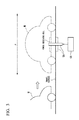
- the wireless power supply device is as shown in FIG. 1 constituted by a power supply coil mechanism 1, a vehicle sensor 2 (movable body sensor), a position control portion (position controller) 3 and an electric power supply control portion (electric power supply controller) 4.
- the power supply coil mechanism 1, the vehicle sensor 2, and the position control portion 3 constitute a position setting member in the present embodiment.
- the wireless power supply device is provided in various types of parking spaces P (rectangular regions).
- a vehicle M enters the parking space P from a predetermined direction and parks, and leaves in the predetermined direction or in the opposite direction.
- the parking space P is provided on the site (on the ground surface) of for example a commercial facility, or in an automated parking lot (multistory parking lot) provided as machinery equipment in a commercial facility.
- the power supply coil mechanism 1 is embedded in the travel surface of the parking space P (electric power supply space) as shown in FIG. 1 , and is set to a vertical position (shown by solid line) by the position control portion 3 in the state of the vehicle M (movable body) not having entered the parking space P (electric power supply space), and is set to a horizontal position (shown by two-dot chain line) by the position control portion 3 in the state of the vehicle M having entered the parking space P (electric power supply space).
- the power supply coil mechanism 1 transmits electric power to the vehicle M by mutually facing from a fixed distance and electromagnetically coupling with a power receiving coil that is provided horizontally in the vehicle M.
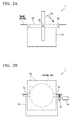
- FIG. 1 in order to make the characteristic of the power supply coil mechanism 1 easily understood, the position of the power supply coil mechanism 1 is schematically shown to change depending on the existence of the vehicle M, but the member that actually changes between a vertical position and a horizontal position by the existence of the vehicle M is a power supply coil 1a that is one of the constituent elements of the power supply coil mechanism 1 as shown in FIG. 2A and FIG. 2B .
- the power supply coil mechanism 1 is constituted by the power supply coil 1a, a pair of rotation shafts 1b and 1b, a housing frame 1c, a reducer 1d, and a motor 1 e.
- the power supply coil 1 a is cast in a square or rectangular plate shape by molding electric wires wound in an annular shape (a helical coil having a predetermined coil diameter) in a resin material that allows an electromagnetic field to pass through.
- the power supply coil 1a wirelessly transmits electric power to the vehicle M by electromagnetically coupling with the power receiving coil through an end surface 1f of the power supply coil 1a, that is, the upper surface (electric power supply surface) facing the power receiving coil (horizontal position) of the vehicle M when the power supply coil 1a is in a horizontal position.
- the power supply coil 1a is molded in a resin material that allows an electromagnetic field to pass through, and the electromagnetic field that is generated by the electric wires and that transfers energy in wireless power supply is not impeded by the resin material, efficient wireless power supply is possible.
- the back surface of the end surface 1f that is, the lower surface (electric power supply back surface) when the power supply coil 1a is in a horizontal position, is magnetically shielded by an appropriate metal so that the magnetic flux is concentrated at the end surface 1f.
- the pair of rotation shafts 1b and 1b are each provided in a projecting manner so that both axial centers are coaxial at the center of one pair of two pairs of parallel surfaces (side surfaces of the power supply coil 1a) that are perpendicular to the end surface 1f. That is to say, both axial centers of the pair of rotation shafts 1b and 1b pass through the center of the power supply coil 1a, and the rotation shafts 1b and 1b project out from both ends of the power supply coil 1a so as to be parallel to the end surface 1f.
- the housing frame 1c is a member with a rectangular parallelopiped shape that is embedded in the parking space P so that the upper end is flush with the travel surface of the parking space P.
- the housing frame 1c is provided with a pair of bearings (not illustrated) that rotatably support the pair of rotation shafts 1b and 1b at one of the two pairs of vertical surfaces that are parallel and facing. That is to say, the housing frame 1c and the aforementioned pair of rotation shafts 1b and 1b constitute a support mechanism that rotatably supports the power supply coil 1a around an axis parallel to the end surface 1f of the power supply coil 1a.
- the pair of bearings are provided at the same depth from the travel surface, and so if the travel surface is horizontal, the rotation shafts 1b and 1b are also horizontal.
- the housing frame 1c forms, as illustrated, a space that houses the lower half portion of the power supply coil 1a in a vertical position, and supports the rotation shafts 1b and 1b so that the end surface 1f is flush with the travel surface of the vehicle M when the power supply coil 1 a is in a horizontal position.
- a receiving portion 1 g that abuts the end portion of the power supply coil 1a when in a horizontal position is formed at one of the pair of vertical surfaces not supporting the pair of rotation shafts 1b and 1b, at a region facing the travel surface.
- the reducer 1d is provided between one of the pair of rotation shafts 1b and 1b and the output shaft of the motor 1e, and is a gear mechanism that reduces rotation of the output shaft to be transmitted to the rotation shaft 1b.
- the motor 1e is an actuator that changes the power supply coil 1a to a horizontal position or a vertical position by rotating the rotation shaft 1b via the reducer 1d. Note that, as the actuator, a hydraulic cylinder or an air cylinder may be used instead of the motor 1 e.
- the vehicle sensor 2 is a monitoring sensor that detects the entry of the vehicle M (movable body) into the parking space P.
- the vehicle sensor 2 detects the vehicle M entering the parking space P using, for example, a medium such as infrared light or laser light.
- the vehicle sensor 2 outputs a detection signal (electrical signal) indicating the vehicle M detection result to the position control portion 3.
- the position control portion 3 is a controller that controls the motor 1 e based on the detection signal.
- the position control portion 3 sets the end surface 1f of the power supply coil 1 a to the vertical position in the state of the vehicle sensor 2 not detecting the entry of the vehicle M into the parking space P, and changes the position of the end surface 1f of the power supply coil 1a from the vertical position to the horizontal position upon detection of entry of the vehicle M into the parking space P.
- the electric power supply control portion 4 is a controller that controls the supply of electrical power (alternating-current power) to the power supply coil 1a based on a position signal input from the position control portion 3.
- the electric power supply control portion 4 is constituted from an inverter circuit (electrical power converter) that outputs alternating-current power to the power supply coil 1 a and an inverter control circuit that supplies a switching signal that is an operation signal to the inverter circuit. Note that the electric power supply control portion 4 is connected by a power cable having flexibility to the power supply coil 1a, whose position freely changes.
- the vehicle sensor 2 of the wireless power supply device monitors all the time or at a predetermined time interval the state of the vicinity of the opening for entry of the vehicle M in the parking space P, and upon detecting that the vehicle M has entered the vicinity of the entry opening, outputs to the position control portion 3 a detection signal (vehicle detection signal) indicating entry of the vehicle M. Then, the position control portion 3, upon the input of the vehicle detection signal from the vehicle sensor 2, outputs a drive signal to the motor 1e to change the position of the end surface 1f of the power supply coil 1a from a vertical position to a horizontal position.
- the vehicle sensor 2 In the case of the vehicle sensor 2 not detecting the entry of the vehicle M into the parking space P, it outputs a detection signal indicating that entry of the vehicle M has not been detected (vehicle non-detection signal) to the position control portion 3. In the state of the vehicle non-detection signal being input, the position control portion 3 stops the output of the drive signal to the motor 1e to keep the end surface 1f of the power supply coil 1a in a vertical position.
- the position of the power supply coil 1a is normally set to a vertical position as shown in FIG. 1 , FIG. 2A and FIG. 2B , and only when the vehicle M has entered the parking space P, as shown by the arrow in FIG. 2A , it is rotated 90 degrees clockwise to be set to a position in which the end portion abuts the receiving portion 1g of the housing frame 1c, that is, a horizontal position.
- the position control portion 3 outputs a position signal indicating the change of the power supply coil 1a to the electric power supply control portion 4. Then, the electric power supply control portion 4, upon receiving the position signal, starts the output of alternating-current power to the power supply coil 1a. That is, the electric power supply control portion 4 does not output alternating-current power to the power supply coil 1 a until the position signal is input from the position control portion 3.
- the power supply coil 1 a is set to a vertical position until the vehicle M enters the parking space P, in the case of for example a foreign object having dropped from above, the foreign object is housed in the housing frame 1c without attaching to the end surface 1f (electric power supply surface) of the power supply coil 1a because of the action of gravity. Accordingly, with the present embodiment it is possible to remove more reliably than before a foreign object from the end surface 1f (electric power supply surface).
- the wireless power supply device as shown in FIG. 3 , is constituted by a power supply coil mechanism 1A and an electric power supply control portion (electric power supply controller) 4A. Note that among these constituent elements, the power supply coil mechanism 1A constitutes the position setting member in the present embodiment.
- the wireless power supply device is provided in various types of parking spaces P (rectangular regions).
- a vehicle M enters the parking space P from a predetermined direction and parks, and leaves in the predetermined direction.
- the parking space P is provided on the site (on the ground surface) of for example a commercial facility, or in an automated parking lot (multistory parking lot) provided as machinery equipment in a commercial facility.
- the power supply coil mechanism 1A is embedded in the travel surface of the parking space P (electric power supply space) as shown in FIG. 3 , and is set to a vertical position (shown by solid line) in the state of the vehicle M (movable body) not having entered the parking space P (electric power supply space), and is set to a horizontal position (shown by two-dot chain line) in the state of the vehicle M having entered the parking space P (electric power supply space).
- the power supply coil mechanism 1 A wirelessly transmits electric power to the vehicle M by mutually facing from a fixed distance and electromagnetically coupling with a power receiving coil that is provided in a horizontal position in the vehicle M.
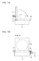
- the position of the power supply coil mechanism 1A is schematically shown to change depending on the existence of the vehicle M, but the member that actually changes between a vertical position and a horizontal position by the existence of the vehicle M is a power supply coil 1a that is one of the constituent elements of the power supply coil mechanism 1A as shown in FIG. 4A, FIG. 4B and FIG. 4C .
- the power supply coil mechanism 1A is constituted by the power supply coil 1a, a pair of rotation shafts 1b and 1b, a housing frame 1c, an abutting portion 1h, and a coil spring 1j (an elastic body).
- the power supply coil 1a has the same shape, constitution, and function as the power supply coil 1a in the first embodiment, and wirelessly transmits electric power to the vehicle M by electromagnetically coupling with the power receiving coil through an end surface 1f of the power supply coil 1a, that is, the upper surface (electric power supply surface) that mutually faces the power receiving coil (horizontal position) of the vehicle M when the power supply coil 1 a is in a horizontal position.
- the pair of rotation shafts 1b and 1b are each provided in a projecting manner so that both axial centers are coaxial at the center of one pair of two pairs of parallel surfaces (side surfaces of the power supply coil 1a) that are perpendicular to the end surface 1f. That is to say, both axial centers of the one pair of rotation shafts 1b and 1b pass through the center of the power supply coil 1a, and project out from both ends of the power supply coil 1a so as to be parallel to the end surface 1f.
- the housing frame 1 c also has the same shape, constitution, and function as the housing frame 1c in the first embodiment.
- the abutting portion 1h is provided on the end surface 1f of the power supply coil 1a so as to project out, and abuts the vehicle M that has entered the parking space P.
- the coil spring 1j is provided between the power supply coil 1a and the housing frame 1c, and by biasing the power supply coil 1a to a predetermined direction, puts the power supply coil 1a in a vertical position under normal conditions.
- the electric power supply control portion 4A is a controller that controls the supply of electrical power (alternating-current power) to the power supply coil 1a by judging whether the power supply coil 1 a is in a horizontal position.
- the electric power supply control portion 4A is constituted from an inverter circuit (electrical power converter) that outputs alternating-current power to the power supply coil 1a and an inverter control circuit that supplies a switching signal that is an operation signal to the inverter circuit.
- the electric power supply control portion 4A is connected by a power cable having flexibility to the power supply coil 1 a, whose position freely changes.
- the power supply coil 1a when the power supply coil 1a is in a horizontal position, the power supply coil 1a is abutting the receiving portion 1g.
- a touch sensor may be provided on the upper surface (end portion) of the receiving portion 1g to detect whether the lower surface of the power supply coil 1a that is in a horizontal position is pressing the touch sensor.
- the power cable be a cable in which insulated twisted wires that are mutually twisted together are covered with a metallic foil or metallic mesh so as to reduce high-frequency radiation.
- the power supply coil 1a maintains a vertical position by the biasing force of the coil spring 1j in the normal state.
- the rear portion (or the end portion) of the vehicle M abuts the abutting portion 1h, whereby the position of the power supply coil 1a changes from the vertical position to the horizontal position.
- the horizontal position is maintained by the abutting portion 1h continuing to abut the bottom of the vehicle M. That is, the power supply coil mechanism 1A, in addition to detecting the entry of the vehicle M into the parking space P, the electric power supply mechanism 1A utilizes the movement of the vehicle M as a power source for changing the position of the power supply coil 1a.
- the position of the power supply coil 1a is normally set to a vertical position as shown in FIG. 3 and FIG. 4A , FIG. 4B and FIG. 4C , and only when the vehicle M has entered the parking space P, as shown by the arrow in FIG. 4A , it is rotated 90 degrees clockwise to be set to a position in which the end portion abuts the receiving portion 1g of the housing frame 1 c, that is, a horizontal position.
- the electric power supply control portion 4A starts the output of alternating-current power to the power supply coil 1a. That is, until the vehicle M enters the electric power supply parking space P, and the position of the power supply coil 1a changes from the vertical position to the horizontal position, the electric power supply control portion 4A does not output alternating-current power to the power supply coil 1a.
- the wireless power supply device similarly to the wireless power supply device according to the first embodiment, since the power supply coil 1a is set to a vertical position until the vehicle M enters the parking space P, it is possible to remove more reliably than before foreign object from the end surface 1f (electric power supply surface).
- the wireless power supply system of the present invention can prevent the intrusion of a foreign object between the power supply coil and the power receiving coil.
Landscapes
- Engineering & Computer Science (AREA)
- Power Engineering (AREA)
- Mechanical Engineering (AREA)
- Computer Networks & Wireless Communication (AREA)
- Transportation (AREA)
- Electric Propulsion And Braking For Vehicles (AREA)
- Charge And Discharge Circuits For Batteries Or The Like (AREA)
Applications Claiming Priority (2)
| Application Number | Priority Date | Filing Date | Title |
|---|---|---|---|
| JP2012244740A JP6065526B2 (ja) | 2012-11-06 | 2012-11-06 | 非接触給電装置 |
| PCT/JP2013/076925 WO2014073298A1 (fr) | 2012-11-06 | 2013-10-03 | Système de délivrance d'énergie électrique sans contact |
Publications (3)
| Publication Number | Publication Date |
|---|---|
| EP2919364A1 true EP2919364A1 (fr) | 2015-09-16 |
| EP2919364A4 EP2919364A4 (fr) | 2016-08-24 |
| EP2919364B1 EP2919364B1 (fr) | 2020-02-26 |
Family
ID=50684415
Family Applications (1)
| Application Number | Title | Priority Date | Filing Date |
|---|---|---|---|
| EP13852415.2A Active EP2919364B1 (fr) | 2012-11-06 | 2013-10-03 | Système de délivrance d'énergie électrique sans contact |
Country Status (5)
| Country | Link |
|---|---|
| US (1) | US9912169B2 (fr) |
| EP (1) | EP2919364B1 (fr) |
| JP (1) | JP6065526B2 (fr) |
| CN (1) | CN104756363B (fr) |
| WO (1) | WO2014073298A1 (fr) |
Families Citing this family (11)
| Publication number | Priority date | Publication date | Assignee | Title |
|---|---|---|---|---|
| JP6043462B2 (ja) * | 2012-09-27 | 2016-12-14 | Ihi運搬機械株式会社 | 車両給電装置 |
| JP6065526B2 (ja) * | 2012-11-06 | 2017-01-25 | 株式会社Ihi | 非接触給電装置 |
| HUE041536T2 (hu) * | 2014-01-20 | 2019-05-28 | Hitachi Automotive Systems Ltd | Érintkezésmentes energiaellátó berendezés forgó testekhez, és nyomatékérzékelõ |
| DE102014222000A1 (de) * | 2014-10-29 | 2016-05-04 | Bayerische Motoren Werke Aktiengesellschaft | Verfahren und Bodeneinheit zum induktiven Laden von Elektro- und Hybridfahrzeugen |
| TWM496152U (zh) * | 2014-11-10 | 2015-02-21 | 廣達電腦股份有限公司 | 具零件模組化設計之電子裝置 |
| KR102168934B1 (ko) * | 2019-05-17 | 2020-10-23 | 수원과학대학교 산학협력단 | 초고자장 초전도 마그넷의 고장 검출 시스템용 무선전력전송장치 |
| JP7245735B2 (ja) * | 2019-06-28 | 2023-03-24 | 株式会社ダイヘン | 送電装置及び送電システム |
| JP7312966B2 (ja) * | 2019-11-28 | 2023-07-24 | パナソニックIpマネジメント株式会社 | 駐車支援装置、車両、駐車支援方法、プログラム、および非一時的記録媒体 |
| US12103411B2 (en) | 2020-10-29 | 2024-10-01 | Ihi Corporation | Power supply device and power supply system |
| JP2022153688A (ja) * | 2021-03-30 | 2022-10-13 | ラピステクノロジー株式会社 | 非接触給電装置、受電装置及び送電装置 |
| US11565594B2 (en) * | 2021-05-27 | 2023-01-31 | Ford Global Technologies, Llc | Vehicle and battery charging system for a vehicle |
Family Cites Families (24)
| Publication number | Priority date | Publication date | Assignee | Title |
|---|---|---|---|---|
| SE0303445L (sv) * | 2003-12-17 | 2005-06-18 | Abb Research Ltd | Verktyg för en industrirobot |
| US9408099B2 (en) | 2008-03-31 | 2016-08-02 | Telefonaktiebolaget Lm Ericsson (Publ) | Method of transmitting CQI reports |
| JP5072690B2 (ja) * | 2008-04-04 | 2012-11-14 | シャープ株式会社 | 無接点式充電装置 |
| JP2010010320A (ja) * | 2008-06-26 | 2010-01-14 | Panasonic Corp | 電子部品実装構造体およびその製造方法 |
| JP5293037B2 (ja) * | 2008-09-19 | 2013-09-18 | ペンタックスリコーイメージング株式会社 | 連写駆動制御装置 |
| US20110074346A1 (en) * | 2009-09-25 | 2011-03-31 | Hall Katherine L | Vehicle charger safety system and method |
| JP5359184B2 (ja) * | 2008-10-22 | 2013-12-04 | トヨタ自動車株式会社 | 給電システム |
| JP5308127B2 (ja) * | 2008-11-17 | 2013-10-09 | 株式会社豊田中央研究所 | 給電システム |
| JP5606098B2 (ja) | 2009-02-25 | 2014-10-15 | マスプロ電工株式会社 | 移動体の電力供給システム |
| CN101854068A (zh) * | 2009-04-03 | 2010-10-06 | 深圳富泰宏精密工业有限公司 | 充电装置 |
| US8901769B2 (en) * | 2009-07-30 | 2014-12-02 | Lutron Electronics Co., Inc. | Load control system having an energy savings mode |
| US8975778B2 (en) * | 2009-07-30 | 2015-03-10 | Lutron Electronics Co., Inc. | Load control system providing manual override of an energy savings mode |
| KR20110042403A (ko) | 2009-10-19 | 2011-04-27 | 김현민 | 전기자동차용 무선충전 시스템 및 그충전방법 |
| EP2515415A4 (fr) | 2009-12-16 | 2016-11-09 | Fujitsu Ltd | Appareil d'émission d'énergie par couplage magnétique résonant et appareil de réception d'énergie par couplage magnétique résonant |
| KR20120055676A (ko) | 2009-12-25 | 2012-05-31 | 가부시끼가이샤 도시바 | 무선 전력 전송 장치 및 수전 장치 |
| WO2011106506A2 (fr) * | 2010-02-25 | 2011-09-01 | Evatran Llc | Procédé et appareil pour le transfert par induction d'une alimentation en courant alternatif entre une unité de charge et un véhicule |
| WO2011156768A2 (fr) * | 2010-06-11 | 2011-12-15 | Mojo Mobility, Inc. | Système de transfert d'énergie sans fil prenant en charge l'interopérabilité et aimants multipolaires à utiliser avec ce système |
| CN102407522B (zh) * | 2010-09-19 | 2014-03-26 | 泰怡凯电器(苏州)有限公司 | 智能机器人系统及其充电对接方法 |
| JP2012080636A (ja) * | 2010-09-30 | 2012-04-19 | Canon Inc | 電子機器及びその受電制御方法 |
| JP5559665B2 (ja) * | 2010-11-30 | 2014-07-23 | 株式会社日立製作所 | 非接触給電装置のインピーダンス整合方法とそれを用いた非接触給電装置 |
| JP5545229B2 (ja) * | 2011-01-26 | 2014-07-09 | 株式会社デンソー | 車載電源装置、路側電源装置、路車間電力伝送システム |
| DE102011108544A1 (de) * | 2011-07-26 | 2012-02-02 | Daimler Ag | Anordnung der Ladespulen beim induktiven Laden in einem Fahrzeug |
| JP5940784B2 (ja) | 2011-09-09 | 2016-06-29 | 国立大学法人埼玉大学 | 移動体用非接触給電装置 |
| JP6065526B2 (ja) * | 2012-11-06 | 2017-01-25 | 株式会社Ihi | 非接触給電装置 |
-
2012
- 2012-11-06 JP JP2012244740A patent/JP6065526B2/ja active Active
-
2013
- 2013-10-03 WO PCT/JP2013/076925 patent/WO2014073298A1/fr not_active Ceased
- 2013-10-03 EP EP13852415.2A patent/EP2919364B1/fr active Active
- 2013-10-03 CN CN201380057330.8A patent/CN104756363B/zh active Active
-
2015
- 2015-04-30 US US14/700,926 patent/US9912169B2/en active Active
Also Published As
| Publication number | Publication date |
|---|---|
| EP2919364A4 (fr) | 2016-08-24 |
| CN104756363A (zh) | 2015-07-01 |
| US9912169B2 (en) | 2018-03-06 |
| CN104756363B (zh) | 2019-09-24 |
| US20150263536A1 (en) | 2015-09-17 |
| JP6065526B2 (ja) | 2017-01-25 |
| JP2014093916A (ja) | 2014-05-19 |
| WO2014073298A1 (fr) | 2014-05-15 |
| EP2919364B1 (fr) | 2020-02-26 |
Similar Documents
| Publication | Publication Date | Title |
|---|---|---|
| US9912169B2 (en) | Wireless power supply system | |
| US10781085B2 (en) | Winch including integrated contactor and motor | |
| JP5431774B2 (ja) | 無線電力伝送装置および無線電力伝送方法 | |
| JP5879566B2 (ja) | 非接触給電装置 | |
| EP2887498A1 (fr) | Aire de stationnement mobile | |
| EP2701284A1 (fr) | Système d'alimentation électrique sans contact de type par résonance, dispositif du côté de la réception de puissance, et dispositif du côté de la transmission de puissance | |
| JP2014236539A (ja) | 非接触充電用送電装置及び電動車両の走行制御システム | |
| KR20120038317A (ko) | 비접촉 전력전달 장치 및 자기유도 방식의 급전장치 | |
| JP7087974B2 (ja) | 位置検出システムおよび位置検出方法 | |
| EP2985872A1 (fr) | Dispositif d'alimentation de puissance, dispositif de réception de puissance, et système d'alimentation de puissance | |
| CN105393430A (zh) | 非接触式供电装置及非接触式受电装置 | |
| AU2017101713A4 (en) | Winch including integrated contactor and motor | |
| EP3145747A1 (fr) | Boîtier pour au moins un dispositif de détection d'objet, unité primaire et ensemble dalle de chaussée | |
| US20180006474A1 (en) | Charging device for the inductive transmission of electrical energy and method for operating the charging device | |
| JP5101188B2 (ja) | 移動監視装置 | |
| KR20170008930A (ko) | 자가전원 센서모듈 및 이를 포함하는 전력설비 모니터 시스템 | |
| CA2986292C (fr) | Treuil comportant un contacteur installe sur le moteur | |
| KR20160062480A (ko) | 크레인의 비상 구동 장치 | |
| CA2986290A1 (fr) | Treuil comportant un contacteur et un moteur integres | |
| JP2015164362A (ja) | 受電ユニット及びそれを有する給電システム | |
| CN203289018U (zh) | 输电线路防外力破坏侦测警示装置的自动安装卸载机 | |
| CN103803414A (zh) | 高架提升传输升降装置 | |
| US20200168019A1 (en) | Garage door sensing |
Legal Events
| Date | Code | Title | Description |
|---|---|---|---|
| PUAI | Public reference made under article 153(3) epc to a published international application that has entered the european phase |
Free format text: ORIGINAL CODE: 0009012 |
|
| 17P | Request for examination filed |
Effective date: 20150507 |
|
| AK | Designated contracting states |
Kind code of ref document: A1 Designated state(s): AL AT BE BG CH CY CZ DE DK EE ES FI FR GB GR HR HU IE IS IT LI LT LU LV MC MK MT NL NO PL PT RO RS SE SI SK SM TR |
|
| AX | Request for extension of the european patent |
Extension state: BA ME |
|
| DAX | Request for extension of the european patent (deleted) | ||
| RA4 | Supplementary search report drawn up and despatched (corrected) |
Effective date: 20160721 |
|
| RIC1 | Information provided on ipc code assigned before grant |
Ipc: H01F 38/14 20060101ALI20160715BHEP Ipc: B60M 7/00 20060101ALI20160715BHEP Ipc: B60L 11/18 20060101AFI20160715BHEP |
|
| STAA | Information on the status of an ep patent application or granted ep patent |
Free format text: STATUS: EXAMINATION IS IN PROGRESS |
|
| REG | Reference to a national code |
Ref country code: DE Ref legal event code: R079 Ref document number: 602013066318 Country of ref document: DE Free format text: PREVIOUS MAIN CLASS: H02J0017000000 Ipc: B60L0053120000 |
|
| 17Q | First examination report despatched |
Effective date: 20190705 |
|
| RIC1 | Information provided on ipc code assigned before grant |
Ipc: B60L 53/12 20190101AFI20190715BHEP |
|
| GRAP | Despatch of communication of intention to grant a patent |
Free format text: ORIGINAL CODE: EPIDOSNIGR1 |
|
| STAA | Information on the status of an ep patent application or granted ep patent |
Free format text: STATUS: GRANT OF PATENT IS INTENDED |
|
| INTG | Intention to grant announced |
Effective date: 20191004 |
|
| GRAS | Grant fee paid |
Free format text: ORIGINAL CODE: EPIDOSNIGR3 |
|
| GRAA | (expected) grant |
Free format text: ORIGINAL CODE: 0009210 |
|
| STAA | Information on the status of an ep patent application or granted ep patent |
Free format text: STATUS: THE PATENT HAS BEEN GRANTED |
|
| AK | Designated contracting states |
Kind code of ref document: B1 Designated state(s): AL AT BE BG CH CY CZ DE DK EE ES FI FR GB GR HR HU IE IS IT LI LT LU LV MC MK MT NL NO PL PT RO RS SE SI SK SM TR |
|
| REG | Reference to a national code |
Ref country code: GB Ref legal event code: FG4D |
|
| REG | Reference to a national code |
Ref country code: CH Ref legal event code: EP |
|
| REG | Reference to a national code |
Ref country code: AT Ref legal event code: REF Ref document number: 1237207 Country of ref document: AT Kind code of ref document: T Effective date: 20200315 |
|
| REG | Reference to a national code |
Ref country code: IE Ref legal event code: FG4D |
|
| REG | Reference to a national code |
Ref country code: DE Ref legal event code: R096 Ref document number: 602013066318 Country of ref document: DE |
|
| PG25 | Lapsed in a contracting state [announced via postgrant information from national office to epo] |
Ref country code: RS Free format text: LAPSE BECAUSE OF FAILURE TO SUBMIT A TRANSLATION OF THE DESCRIPTION OR TO PAY THE FEE WITHIN THE PRESCRIBED TIME-LIMIT Effective date: 20200226 Ref country code: NO Free format text: LAPSE BECAUSE OF FAILURE TO SUBMIT A TRANSLATION OF THE DESCRIPTION OR TO PAY THE FEE WITHIN THE PRESCRIBED TIME-LIMIT Effective date: 20200526 Ref country code: FI Free format text: LAPSE BECAUSE OF FAILURE TO SUBMIT A TRANSLATION OF THE DESCRIPTION OR TO PAY THE FEE WITHIN THE PRESCRIBED TIME-LIMIT Effective date: 20200226 |
|
| REG | Reference to a national code |
Ref country code: NL Ref legal event code: MP Effective date: 20200226 |
|
| REG | Reference to a national code |
Ref country code: LT Ref legal event code: MG4D |
|
| PG25 | Lapsed in a contracting state [announced via postgrant information from national office to epo] |
Ref country code: HR Free format text: LAPSE BECAUSE OF FAILURE TO SUBMIT A TRANSLATION OF THE DESCRIPTION OR TO PAY THE FEE WITHIN THE PRESCRIBED TIME-LIMIT Effective date: 20200226 Ref country code: GR Free format text: LAPSE BECAUSE OF FAILURE TO SUBMIT A TRANSLATION OF THE DESCRIPTION OR TO PAY THE FEE WITHIN THE PRESCRIBED TIME-LIMIT Effective date: 20200527 Ref country code: IS Free format text: LAPSE BECAUSE OF FAILURE TO SUBMIT A TRANSLATION OF THE DESCRIPTION OR TO PAY THE FEE WITHIN THE PRESCRIBED TIME-LIMIT Effective date: 20200626 Ref country code: SE Free format text: LAPSE BECAUSE OF FAILURE TO SUBMIT A TRANSLATION OF THE DESCRIPTION OR TO PAY THE FEE WITHIN THE PRESCRIBED TIME-LIMIT Effective date: 20200226 Ref country code: LV Free format text: LAPSE BECAUSE OF FAILURE TO SUBMIT A TRANSLATION OF THE DESCRIPTION OR TO PAY THE FEE WITHIN THE PRESCRIBED TIME-LIMIT Effective date: 20200226 Ref country code: BG Free format text: LAPSE BECAUSE OF FAILURE TO SUBMIT A TRANSLATION OF THE DESCRIPTION OR TO PAY THE FEE WITHIN THE PRESCRIBED TIME-LIMIT Effective date: 20200526 |
|
| PG25 | Lapsed in a contracting state [announced via postgrant information from national office to epo] |
Ref country code: NL Free format text: LAPSE BECAUSE OF FAILURE TO SUBMIT A TRANSLATION OF THE DESCRIPTION OR TO PAY THE FEE WITHIN THE PRESCRIBED TIME-LIMIT Effective date: 20200226 |
|
| PG25 | Lapsed in a contracting state [announced via postgrant information from national office to epo] |
Ref country code: ES Free format text: LAPSE BECAUSE OF FAILURE TO SUBMIT A TRANSLATION OF THE DESCRIPTION OR TO PAY THE FEE WITHIN THE PRESCRIBED TIME-LIMIT Effective date: 20200226 Ref country code: CZ Free format text: LAPSE BECAUSE OF FAILURE TO SUBMIT A TRANSLATION OF THE DESCRIPTION OR TO PAY THE FEE WITHIN THE PRESCRIBED TIME-LIMIT Effective date: 20200226 Ref country code: RO Free format text: LAPSE BECAUSE OF FAILURE TO SUBMIT A TRANSLATION OF THE DESCRIPTION OR TO PAY THE FEE WITHIN THE PRESCRIBED TIME-LIMIT Effective date: 20200226 Ref country code: PT Free format text: LAPSE BECAUSE OF FAILURE TO SUBMIT A TRANSLATION OF THE DESCRIPTION OR TO PAY THE FEE WITHIN THE PRESCRIBED TIME-LIMIT Effective date: 20200719 Ref country code: SM Free format text: LAPSE BECAUSE OF FAILURE TO SUBMIT A TRANSLATION OF THE DESCRIPTION OR TO PAY THE FEE WITHIN THE PRESCRIBED TIME-LIMIT Effective date: 20200226 Ref country code: EE Free format text: LAPSE BECAUSE OF FAILURE TO SUBMIT A TRANSLATION OF THE DESCRIPTION OR TO PAY THE FEE WITHIN THE PRESCRIBED TIME-LIMIT Effective date: 20200226 Ref country code: LT Free format text: LAPSE BECAUSE OF FAILURE TO SUBMIT A TRANSLATION OF THE DESCRIPTION OR TO PAY THE FEE WITHIN THE PRESCRIBED TIME-LIMIT Effective date: 20200226 Ref country code: DK Free format text: LAPSE BECAUSE OF FAILURE TO SUBMIT A TRANSLATION OF THE DESCRIPTION OR TO PAY THE FEE WITHIN THE PRESCRIBED TIME-LIMIT Effective date: 20200226 Ref country code: SK Free format text: LAPSE BECAUSE OF FAILURE TO SUBMIT A TRANSLATION OF THE DESCRIPTION OR TO PAY THE FEE WITHIN THE PRESCRIBED TIME-LIMIT Effective date: 20200226 |
|
| REG | Reference to a national code |
Ref country code: AT Ref legal event code: MK05 Ref document number: 1237207 Country of ref document: AT Kind code of ref document: T Effective date: 20200226 |
|
| REG | Reference to a national code |
Ref country code: DE Ref legal event code: R097 Ref document number: 602013066318 Country of ref document: DE |
|
| PLBE | No opposition filed within time limit |
Free format text: ORIGINAL CODE: 0009261 |
|
| STAA | Information on the status of an ep patent application or granted ep patent |
Free format text: STATUS: NO OPPOSITION FILED WITHIN TIME LIMIT |
|
| PG25 | Lapsed in a contracting state [announced via postgrant information from national office to epo] |
Ref country code: IT Free format text: LAPSE BECAUSE OF FAILURE TO SUBMIT A TRANSLATION OF THE DESCRIPTION OR TO PAY THE FEE WITHIN THE PRESCRIBED TIME-LIMIT Effective date: 20200226 Ref country code: AT Free format text: LAPSE BECAUSE OF FAILURE TO SUBMIT A TRANSLATION OF THE DESCRIPTION OR TO PAY THE FEE WITHIN THE PRESCRIBED TIME-LIMIT Effective date: 20200226 |
|
| 26N | No opposition filed |
Effective date: 20201127 |
|
| PG25 | Lapsed in a contracting state [announced via postgrant information from national office to epo] |
Ref country code: SI Free format text: LAPSE BECAUSE OF FAILURE TO SUBMIT A TRANSLATION OF THE DESCRIPTION OR TO PAY THE FEE WITHIN THE PRESCRIBED TIME-LIMIT Effective date: 20200226 Ref country code: PL Free format text: LAPSE BECAUSE OF FAILURE TO SUBMIT A TRANSLATION OF THE DESCRIPTION OR TO PAY THE FEE WITHIN THE PRESCRIBED TIME-LIMIT Effective date: 20200226 |
|
| REG | Reference to a national code |
Ref country code: CH Ref legal event code: PL |
|
| GBPC | Gb: european patent ceased through non-payment of renewal fee |
Effective date: 20201003 |
|
| PG25 | Lapsed in a contracting state [announced via postgrant information from national office to epo] |
Ref country code: MC Free format text: LAPSE BECAUSE OF FAILURE TO SUBMIT A TRANSLATION OF THE DESCRIPTION OR TO PAY THE FEE WITHIN THE PRESCRIBED TIME-LIMIT Effective date: 20200226 Ref country code: LU Free format text: LAPSE BECAUSE OF NON-PAYMENT OF DUE FEES Effective date: 20201003 |
|
| REG | Reference to a national code |
Ref country code: BE Ref legal event code: MM Effective date: 20201031 |
|
| PG25 | Lapsed in a contracting state [announced via postgrant information from national office to epo] |
Ref country code: FR Free format text: LAPSE BECAUSE OF NON-PAYMENT OF DUE FEES Effective date: 20201031 |
|
| PG25 | Lapsed in a contracting state [announced via postgrant information from national office to epo] |
Ref country code: BE Free format text: LAPSE BECAUSE OF NON-PAYMENT OF DUE FEES Effective date: 20201031 Ref country code: CH Free format text: LAPSE BECAUSE OF NON-PAYMENT OF DUE FEES Effective date: 20201031 Ref country code: GB Free format text: LAPSE BECAUSE OF NON-PAYMENT OF DUE FEES Effective date: 20201003 Ref country code: LI Free format text: LAPSE BECAUSE OF NON-PAYMENT OF DUE FEES Effective date: 20201031 |
|
| PG25 | Lapsed in a contracting state [announced via postgrant information from national office to epo] |
Ref country code: IE Free format text: LAPSE BECAUSE OF NON-PAYMENT OF DUE FEES Effective date: 20201003 |
|
| PG25 | Lapsed in a contracting state [announced via postgrant information from national office to epo] |
Ref country code: TR Free format text: LAPSE BECAUSE OF FAILURE TO SUBMIT A TRANSLATION OF THE DESCRIPTION OR TO PAY THE FEE WITHIN THE PRESCRIBED TIME-LIMIT Effective date: 20200226 Ref country code: MT Free format text: LAPSE BECAUSE OF FAILURE TO SUBMIT A TRANSLATION OF THE DESCRIPTION OR TO PAY THE FEE WITHIN THE PRESCRIBED TIME-LIMIT Effective date: 20200226 Ref country code: CY Free format text: LAPSE BECAUSE OF FAILURE TO SUBMIT A TRANSLATION OF THE DESCRIPTION OR TO PAY THE FEE WITHIN THE PRESCRIBED TIME-LIMIT Effective date: 20200226 |
|
| PG25 | Lapsed in a contracting state [announced via postgrant information from national office to epo] |
Ref country code: MK Free format text: LAPSE BECAUSE OF FAILURE TO SUBMIT A TRANSLATION OF THE DESCRIPTION OR TO PAY THE FEE WITHIN THE PRESCRIBED TIME-LIMIT Effective date: 20200226 Ref country code: AL Free format text: LAPSE BECAUSE OF FAILURE TO SUBMIT A TRANSLATION OF THE DESCRIPTION OR TO PAY THE FEE WITHIN THE PRESCRIBED TIME-LIMIT Effective date: 20200226 |
|
| PGFP | Annual fee paid to national office [announced via postgrant information from national office to epo] |
Ref country code: DE Payment date: 20250923 Year of fee payment: 13 |