EP2985872A1 - Dispositif d'alimentation de puissance, dispositif de réception de puissance, et système d'alimentation de puissance - Google Patents
Dispositif d'alimentation de puissance, dispositif de réception de puissance, et système d'alimentation de puissance Download PDFInfo
- Publication number
- EP2985872A1 EP2985872A1 EP14773722.5A EP14773722A EP2985872A1 EP 2985872 A1 EP2985872 A1 EP 2985872A1 EP 14773722 A EP14773722 A EP 14773722A EP 2985872 A1 EP2985872 A1 EP 2985872A1
- Authority
- EP
- European Patent Office
- Prior art keywords
- power
- power supply
- vehicle
- coil
- power receiving
- Prior art date
- Legal status (The legal status is an assumption and is not a legal conclusion. Google has not performed a legal analysis and makes no representation as to the accuracy of the status listed.)
- Withdrawn
Links
Images


Classifications
-
- B—PERFORMING OPERATIONS; TRANSPORTING
- B60—VEHICLES IN GENERAL
- B60L—PROPULSION OF ELECTRICALLY-PROPELLED VEHICLES; SUPPLYING ELECTRIC POWER FOR AUXILIARY EQUIPMENT OF ELECTRICALLY-PROPELLED VEHICLES; ELECTRODYNAMIC BRAKE SYSTEMS FOR VEHICLES IN GENERAL; MAGNETIC SUSPENSION OR LEVITATION FOR VEHICLES; MONITORING OPERATING VARIABLES OF ELECTRICALLY-PROPELLED VEHICLES; ELECTRIC SAFETY DEVICES FOR ELECTRICALLY-PROPELLED VEHICLES
- B60L53/00—Methods of charging batteries, specially adapted for electric vehicles; Charging stations or on-board charging equipment therefor; Exchange of energy storage elements in electric vehicles
- B60L53/30—Constructional details of charging stations
-
- B—PERFORMING OPERATIONS; TRANSPORTING
- B60—VEHICLES IN GENERAL
- B60L—PROPULSION OF ELECTRICALLY-PROPELLED VEHICLES; SUPPLYING ELECTRIC POWER FOR AUXILIARY EQUIPMENT OF ELECTRICALLY-PROPELLED VEHICLES; ELECTRODYNAMIC BRAKE SYSTEMS FOR VEHICLES IN GENERAL; MAGNETIC SUSPENSION OR LEVITATION FOR VEHICLES; MONITORING OPERATING VARIABLES OF ELECTRICALLY-PROPELLED VEHICLES; ELECTRIC SAFETY DEVICES FOR ELECTRICALLY-PROPELLED VEHICLES
- B60L50/00—Electric propulsion with power supplied within the vehicle
- B60L50/10—Electric propulsion with power supplied within the vehicle using propulsion power supplied by engine-driven generators, e.g. generators driven by combustion engines
- B60L50/16—Electric propulsion with power supplied within the vehicle using propulsion power supplied by engine-driven generators, e.g. generators driven by combustion engines with provision for separate direct mechanical propulsion
-
- B—PERFORMING OPERATIONS; TRANSPORTING
- B60—VEHICLES IN GENERAL
- B60L—PROPULSION OF ELECTRICALLY-PROPELLED VEHICLES; SUPPLYING ELECTRIC POWER FOR AUXILIARY EQUIPMENT OF ELECTRICALLY-PROPELLED VEHICLES; ELECTRODYNAMIC BRAKE SYSTEMS FOR VEHICLES IN GENERAL; MAGNETIC SUSPENSION OR LEVITATION FOR VEHICLES; MONITORING OPERATING VARIABLES OF ELECTRICALLY-PROPELLED VEHICLES; ELECTRIC SAFETY DEVICES FOR ELECTRICALLY-PROPELLED VEHICLES
- B60L50/00—Electric propulsion with power supplied within the vehicle
- B60L50/50—Electric propulsion with power supplied within the vehicle using propulsion power supplied by batteries or fuel cells
- B60L50/52—Electric propulsion with power supplied within the vehicle using propulsion power supplied by batteries or fuel cells characterised by DC-motors
-
- B—PERFORMING OPERATIONS; TRANSPORTING
- B60—VEHICLES IN GENERAL
- B60L—PROPULSION OF ELECTRICALLY-PROPELLED VEHICLES; SUPPLYING ELECTRIC POWER FOR AUXILIARY EQUIPMENT OF ELECTRICALLY-PROPELLED VEHICLES; ELECTRODYNAMIC BRAKE SYSTEMS FOR VEHICLES IN GENERAL; MAGNETIC SUSPENSION OR LEVITATION FOR VEHICLES; MONITORING OPERATING VARIABLES OF ELECTRICALLY-PROPELLED VEHICLES; ELECTRIC SAFETY DEVICES FOR ELECTRICALLY-PROPELLED VEHICLES
- B60L50/00—Electric propulsion with power supplied within the vehicle
- B60L50/50—Electric propulsion with power supplied within the vehicle using propulsion power supplied by batteries or fuel cells
- B60L50/60—Electric propulsion with power supplied within the vehicle using propulsion power supplied by batteries or fuel cells using power supplied by batteries
- B60L50/66—Arrangements of batteries
-
- B—PERFORMING OPERATIONS; TRANSPORTING
- B60—VEHICLES IN GENERAL
- B60L—PROPULSION OF ELECTRICALLY-PROPELLED VEHICLES; SUPPLYING ELECTRIC POWER FOR AUXILIARY EQUIPMENT OF ELECTRICALLY-PROPELLED VEHICLES; ELECTRODYNAMIC BRAKE SYSTEMS FOR VEHICLES IN GENERAL; MAGNETIC SUSPENSION OR LEVITATION FOR VEHICLES; MONITORING OPERATING VARIABLES OF ELECTRICALLY-PROPELLED VEHICLES; ELECTRIC SAFETY DEVICES FOR ELECTRICALLY-PROPELLED VEHICLES
- B60L53/00—Methods of charging batteries, specially adapted for electric vehicles; Charging stations or on-board charging equipment therefor; Exchange of energy storage elements in electric vehicles
- B60L53/10—Methods of charging batteries, specially adapted for electric vehicles; Charging stations or on-board charging equipment therefor; Exchange of energy storage elements in electric vehicles characterised by the energy transfer between the charging station and the vehicle
- B60L53/12—Inductive energy transfer
-
- B—PERFORMING OPERATIONS; TRANSPORTING
- B60—VEHICLES IN GENERAL
- B60L—PROPULSION OF ELECTRICALLY-PROPELLED VEHICLES; SUPPLYING ELECTRIC POWER FOR AUXILIARY EQUIPMENT OF ELECTRICALLY-PROPELLED VEHICLES; ELECTRODYNAMIC BRAKE SYSTEMS FOR VEHICLES IN GENERAL; MAGNETIC SUSPENSION OR LEVITATION FOR VEHICLES; MONITORING OPERATING VARIABLES OF ELECTRICALLY-PROPELLED VEHICLES; ELECTRIC SAFETY DEVICES FOR ELECTRICALLY-PROPELLED VEHICLES
- B60L53/00—Methods of charging batteries, specially adapted for electric vehicles; Charging stations or on-board charging equipment therefor; Exchange of energy storage elements in electric vehicles
- B60L53/10—Methods of charging batteries, specially adapted for electric vehicles; Charging stations or on-board charging equipment therefor; Exchange of energy storage elements in electric vehicles characterised by the energy transfer between the charging station and the vehicle
- B60L53/12—Inductive energy transfer
- B60L53/126—Methods for pairing a vehicle and a charging station, e.g. establishing a one-to-one relation between a wireless power transmitter and a wireless power receiver
-
- B—PERFORMING OPERATIONS; TRANSPORTING
- B60—VEHICLES IN GENERAL
- B60L—PROPULSION OF ELECTRICALLY-PROPELLED VEHICLES; SUPPLYING ELECTRIC POWER FOR AUXILIARY EQUIPMENT OF ELECTRICALLY-PROPELLED VEHICLES; ELECTRODYNAMIC BRAKE SYSTEMS FOR VEHICLES IN GENERAL; MAGNETIC SUSPENSION OR LEVITATION FOR VEHICLES; MONITORING OPERATING VARIABLES OF ELECTRICALLY-PROPELLED VEHICLES; ELECTRIC SAFETY DEVICES FOR ELECTRICALLY-PROPELLED VEHICLES
- B60L53/00—Methods of charging batteries, specially adapted for electric vehicles; Charging stations or on-board charging equipment therefor; Exchange of energy storage elements in electric vehicles
- B60L53/30—Constructional details of charging stations
- B60L53/35—Means for automatic or assisted adjustment of the relative position of charging devices and vehicles
- B60L53/36—Means for automatic or assisted adjustment of the relative position of charging devices and vehicles by positioning the vehicle
-
- B—PERFORMING OPERATIONS; TRANSPORTING
- B60—VEHICLES IN GENERAL
- B60L—PROPULSION OF ELECTRICALLY-PROPELLED VEHICLES; SUPPLYING ELECTRIC POWER FOR AUXILIARY EQUIPMENT OF ELECTRICALLY-PROPELLED VEHICLES; ELECTRODYNAMIC BRAKE SYSTEMS FOR VEHICLES IN GENERAL; MAGNETIC SUSPENSION OR LEVITATION FOR VEHICLES; MONITORING OPERATING VARIABLES OF ELECTRICALLY-PROPELLED VEHICLES; ELECTRIC SAFETY DEVICES FOR ELECTRICALLY-PROPELLED VEHICLES
- B60L53/00—Methods of charging batteries, specially adapted for electric vehicles; Charging stations or on-board charging equipment therefor; Exchange of energy storage elements in electric vehicles
- B60L53/30—Constructional details of charging stations
- B60L53/35—Means for automatic or assisted adjustment of the relative position of charging devices and vehicles
- B60L53/38—Means for automatic or assisted adjustment of the relative position of charging devices and vehicles specially adapted for charging by inductive energy transfer
-
- B—PERFORMING OPERATIONS; TRANSPORTING
- B60—VEHICLES IN GENERAL
- B60L—PROPULSION OF ELECTRICALLY-PROPELLED VEHICLES; SUPPLYING ELECTRIC POWER FOR AUXILIARY EQUIPMENT OF ELECTRICALLY-PROPELLED VEHICLES; ELECTRODYNAMIC BRAKE SYSTEMS FOR VEHICLES IN GENERAL; MAGNETIC SUSPENSION OR LEVITATION FOR VEHICLES; MONITORING OPERATING VARIABLES OF ELECTRICALLY-PROPELLED VEHICLES; ELECTRIC SAFETY DEVICES FOR ELECTRICALLY-PROPELLED VEHICLES
- B60L53/00—Methods of charging batteries, specially adapted for electric vehicles; Charging stations or on-board charging equipment therefor; Exchange of energy storage elements in electric vehicles
- B60L53/60—Monitoring or controlling charging stations
- B60L53/65—Monitoring or controlling charging stations involving identification of vehicles or their battery types
-
- H—ELECTRICITY
- H02—GENERATION; CONVERSION OR DISTRIBUTION OF ELECTRIC POWER
- H02J—ELECTRIC POWER NETWORKS; CIRCUIT ARRANGEMENTS OR SYSTEMS FOR SUPPLYING OR DISTRIBUTING ELECTRIC POWER; SYSTEMS FOR STORING ELECTRIC ENERGY
- H02J50/00—Circuit arrangements or systems for wireless supply or distribution of electric power
- H02J50/10—Circuit arrangements or systems for wireless supply or distribution of electric power using inductive coupling
-
- H—ELECTRICITY
- H02—GENERATION; CONVERSION OR DISTRIBUTION OF ELECTRIC POWER
- H02J—ELECTRIC POWER NETWORKS; CIRCUIT ARRANGEMENTS OR SYSTEMS FOR SUPPLYING OR DISTRIBUTING ELECTRIC POWER; SYSTEMS FOR STORING ELECTRIC ENERGY
- H02J50/00—Circuit arrangements or systems for wireless supply or distribution of electric power
- H02J50/80—Circuit arrangements or systems for wireless supply or distribution of electric power involving the exchange of data, concerning supply or distribution of electric power, between transmitting devices and receiving devices
-
- H—ELECTRICITY
- H02—GENERATION; CONVERSION OR DISTRIBUTION OF ELECTRIC POWER
- H02J—ELECTRIC POWER NETWORKS; CIRCUIT ARRANGEMENTS OR SYSTEMS FOR SUPPLYING OR DISTRIBUTING ELECTRIC POWER; SYSTEMS FOR STORING ELECTRIC ENERGY
- H02J50/00—Circuit arrangements or systems for wireless supply or distribution of electric power
- H02J50/90—Circuit arrangements or systems for wireless supply or distribution of electric power involving detection or optimisation of position, e.g. alignment
-
- B—PERFORMING OPERATIONS; TRANSPORTING
- B60—VEHICLES IN GENERAL
- B60L—PROPULSION OF ELECTRICALLY-PROPELLED VEHICLES; SUPPLYING ELECTRIC POWER FOR AUXILIARY EQUIPMENT OF ELECTRICALLY-PROPELLED VEHICLES; ELECTRODYNAMIC BRAKE SYSTEMS FOR VEHICLES IN GENERAL; MAGNETIC SUSPENSION OR LEVITATION FOR VEHICLES; MONITORING OPERATING VARIABLES OF ELECTRICALLY-PROPELLED VEHICLES; ELECTRIC SAFETY DEVICES FOR ELECTRICALLY-PROPELLED VEHICLES
- B60L2240/00—Control parameters of input or output; Target parameters
- B60L2240/10—Vehicle control parameters
- B60L2240/30—Parking brake position
-
- H—ELECTRICITY
- H02—GENERATION; CONVERSION OR DISTRIBUTION OF ELECTRIC POWER
- H02J—ELECTRIC POWER NETWORKS; CIRCUIT ARRANGEMENTS OR SYSTEMS FOR SUPPLYING OR DISTRIBUTING ELECTRIC POWER; SYSTEMS FOR STORING ELECTRIC ENERGY
- H02J50/00—Circuit arrangements or systems for wireless supply or distribution of electric power
- H02J50/10—Circuit arrangements or systems for wireless supply or distribution of electric power using inductive coupling
- H02J50/12—Circuit arrangements or systems for wireless supply or distribution of electric power using inductive coupling of the resonant type
-
- Y—GENERAL TAGGING OF NEW TECHNOLOGICAL DEVELOPMENTS; GENERAL TAGGING OF CROSS-SECTIONAL TECHNOLOGIES SPANNING OVER SEVERAL SECTIONS OF THE IPC; TECHNICAL SUBJECTS COVERED BY FORMER USPC CROSS-REFERENCE ART COLLECTIONS [XRACs] AND DIGESTS
- Y02—TECHNOLOGIES OR APPLICATIONS FOR MITIGATION OR ADAPTATION AGAINST CLIMATE CHANGE
- Y02T—CLIMATE CHANGE MITIGATION TECHNOLOGIES RELATED TO TRANSPORTATION
- Y02T10/00—Road transport of goods or passengers
- Y02T10/60—Other road transportation technologies with climate change mitigation effect
- Y02T10/70—Energy storage systems for electromobility, e.g. batteries
-
- Y—GENERAL TAGGING OF NEW TECHNOLOGICAL DEVELOPMENTS; GENERAL TAGGING OF CROSS-SECTIONAL TECHNOLOGIES SPANNING OVER SEVERAL SECTIONS OF THE IPC; TECHNICAL SUBJECTS COVERED BY FORMER USPC CROSS-REFERENCE ART COLLECTIONS [XRACs] AND DIGESTS
- Y02—TECHNOLOGIES OR APPLICATIONS FOR MITIGATION OR ADAPTATION AGAINST CLIMATE CHANGE
- Y02T—CLIMATE CHANGE MITIGATION TECHNOLOGIES RELATED TO TRANSPORTATION
- Y02T10/00—Road transport of goods or passengers
- Y02T10/60—Other road transportation technologies with climate change mitigation effect
- Y02T10/7072—Electromobility specific charging systems or methods for batteries, ultracapacitors, supercapacitors or double-layer capacitors
-
- Y—GENERAL TAGGING OF NEW TECHNOLOGICAL DEVELOPMENTS; GENERAL TAGGING OF CROSS-SECTIONAL TECHNOLOGIES SPANNING OVER SEVERAL SECTIONS OF THE IPC; TECHNICAL SUBJECTS COVERED BY FORMER USPC CROSS-REFERENCE ART COLLECTIONS [XRACs] AND DIGESTS
- Y02—TECHNOLOGIES OR APPLICATIONS FOR MITIGATION OR ADAPTATION AGAINST CLIMATE CHANGE
- Y02T—CLIMATE CHANGE MITIGATION TECHNOLOGIES RELATED TO TRANSPORTATION
- Y02T90/00—Enabling technologies or technologies with a potential or indirect contribution to GHG emissions mitigation
- Y02T90/10—Technologies relating to charging of electric vehicles
- Y02T90/12—Electric charging stations
-
- Y—GENERAL TAGGING OF NEW TECHNOLOGICAL DEVELOPMENTS; GENERAL TAGGING OF CROSS-SECTIONAL TECHNOLOGIES SPANNING OVER SEVERAL SECTIONS OF THE IPC; TECHNICAL SUBJECTS COVERED BY FORMER USPC CROSS-REFERENCE ART COLLECTIONS [XRACs] AND DIGESTS
- Y02—TECHNOLOGIES OR APPLICATIONS FOR MITIGATION OR ADAPTATION AGAINST CLIMATE CHANGE
- Y02T—CLIMATE CHANGE MITIGATION TECHNOLOGIES RELATED TO TRANSPORTATION
- Y02T90/00—Enabling technologies or technologies with a potential or indirect contribution to GHG emissions mitigation
- Y02T90/10—Technologies relating to charging of electric vehicles
- Y02T90/14—Plug-in electric vehicles
-
- Y—GENERAL TAGGING OF NEW TECHNOLOGICAL DEVELOPMENTS; GENERAL TAGGING OF CROSS-SECTIONAL TECHNOLOGIES SPANNING OVER SEVERAL SECTIONS OF THE IPC; TECHNICAL SUBJECTS COVERED BY FORMER USPC CROSS-REFERENCE ART COLLECTIONS [XRACs] AND DIGESTS
- Y02—TECHNOLOGIES OR APPLICATIONS FOR MITIGATION OR ADAPTATION AGAINST CLIMATE CHANGE
- Y02T—CLIMATE CHANGE MITIGATION TECHNOLOGIES RELATED TO TRANSPORTATION
- Y02T90/00—Enabling technologies or technologies with a potential or indirect contribution to GHG emissions mitigation
- Y02T90/10—Technologies relating to charging of electric vehicles
- Y02T90/16—Information or communication technologies improving the operation of electric vehicles
-
- Y—GENERAL TAGGING OF NEW TECHNOLOGICAL DEVELOPMENTS; GENERAL TAGGING OF CROSS-SECTIONAL TECHNOLOGIES SPANNING OVER SEVERAL SECTIONS OF THE IPC; TECHNICAL SUBJECTS COVERED BY FORMER USPC CROSS-REFERENCE ART COLLECTIONS [XRACs] AND DIGESTS
- Y02—TECHNOLOGIES OR APPLICATIONS FOR MITIGATION OR ADAPTATION AGAINST CLIMATE CHANGE
- Y02T—CLIMATE CHANGE MITIGATION TECHNOLOGIES RELATED TO TRANSPORTATION
- Y02T90/00—Enabling technologies or technologies with a potential or indirect contribution to GHG emissions mitigation
- Y02T90/10—Technologies relating to charging of electric vehicles
- Y02T90/16—Information or communication technologies improving the operation of electric vehicles
- Y02T90/167—Systems integrating technologies related to power network operation and communication or information technologies for supporting the interoperability of electric or hybrid vehicles, i.e. smartgrids as interface for battery charging of electric vehicles [EV] or hybrid vehicles [HEV]
-
- Y—GENERAL TAGGING OF NEW TECHNOLOGICAL DEVELOPMENTS; GENERAL TAGGING OF CROSS-SECTIONAL TECHNOLOGIES SPANNING OVER SEVERAL SECTIONS OF THE IPC; TECHNICAL SUBJECTS COVERED BY FORMER USPC CROSS-REFERENCE ART COLLECTIONS [XRACs] AND DIGESTS
- Y04—INFORMATION OR COMMUNICATION TECHNOLOGIES HAVING AN IMPACT ON OTHER TECHNOLOGY AREAS
- Y04S—SYSTEMS INTEGRATING TECHNOLOGIES RELATED TO POWER NETWORK OPERATION, COMMUNICATION OR INFORMATION TECHNOLOGIES FOR IMPROVING THE ELECTRICAL POWER GENERATION, TRANSMISSION, DISTRIBUTION, MANAGEMENT OR USAGE, i.e. SMART GRIDS
- Y04S30/00—Systems supporting specific end-user applications in the sector of transportation
- Y04S30/10—Systems supporting the interoperability of electric or hybrid vehicles
- Y04S30/14—Details associated with the interoperability, e.g. vehicle recognition, authentication, identification or billing
Definitions
- the present invention relates to a power supply apparatus that supplies power to a power receiving coil provided on a vehicle using an electromagnetic force, and also relates to a power receiving apparatus and a power supply system.
- Patent Literature 1 (hereinafter, referred to as "PTL 1")
- the power supply apparatus in PTL 1 includes two units; a power transmission unit and a power receiving unit.
- the power transmission unit accommodates a true-circle power transmission coil and is provided on a road side of a parking space or the like at a position where the vehicle is parked.
- the power receiving unit accommodates a true-circle power receiving coil, and is provided on the bottom surface of the vehicle at a position opposite to the power transmission unit installed on the ground.
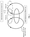
- FIG. 1 illustrates a relationship between the position of the power receiving coil (secondary coil shown by broken line or single-dot dashed line) with respect to the power supply coil (primary coil shown by solid line) and an interlinkage magnetic flux.
- the power supply coil and the power receiving coil have an identical shape.
- Position A the position of the power receiving coil where the central axis of the power supply coil (not shown) overlaps the central axis of the power receiving coil (not shown) is Position A
- Position B the position of the power receiving coil shifted by half the coil diameter from Position A.
- the orientation of the interlinking magnetic flux changes between a case where the power receiving coil that receives a magnetic flux generated from the power supply coil is located at Position A and a case where the power receiving coil is located at Position B.
- the magnetic flux is interlinked in such a way that the magnetic flux is canceled out, so that no current flows through the power receiving coil and the power supplied becomes 0 (null point).
- FIG. 2A illustrates a power supply characteristic with respect to a displacement between the power supply coil and the power receiving coil.
- the horizontal axis represents displacement d2 [cm] of the power receiving coil with respect to the power supply coil and the vertical axis represents the degree of coupling [dB].
- the power supply coil and the power receiving coil have the same coil diameter of 50 [cm].
- FIG. 2B shows that when the power receiving coil is located at Position B (that is, position shifted by half the coil diameter (25 [cm]) from Position A with respect to the power supply coil, the degree of coupling, that is, supplied power becomes 0 (null point), and power supply efficiency drastically decreases.
- An object of the present invention is to provide a power supply apparatus, a power receiving apparatus and a power supply system capable of preventing deterioration of power supply efficiency by increasing an allowable range of displacements of a power receiving coil with respect to a power supply coil, while facilitating mounting of the power receiving coil on the vehicle.
- a power supply apparatus supplies power to a vehicle including a power receiving coil, using an electromagnetic force, the power supply apparatus including a power supply coil that faces the power receiving coil and that supplies power, in which the power supply coil has a shape substantially identical to that of the power receiving coil, and has a first length longer than a second length, the first length being a length of the vehicle in a left and right direction of the vehicle, the second length being a length of the vehicle in a front and rear direction of the vehicle.
- a power receiving apparatus is provided on a vehicle and receives power supply from a power supply apparatus comprising a power supply coil, using an electromagnetic force, the power receiving apparatus including a power receiving coil that faces the power supply coil and receives power supply, in which the power receiving coil has a shape substantially identical to that of the power supply coil, and has a first length longer than a second length, the first length being a length of the vehicle in a left and right direction of the vehicle, the second length being a length of the vehicle in a front and rear direction of the vehicle.
- a power supply system includes: a power receiving apparatus provided on a vehicle; and a power supply apparatus that supplies power to the vehicle using an electromagnetic force, in which the power receiving apparatus comprises a power receiving coil that faces the power supply apparatus and receives power supply, the power supply apparatus includes a power supply coil that faces the power receiving coil and supplies power, and the power receiving coil and the power supply coil have shapes substantially identical with each other, and have lengths in a left and right direction of the vehicle, the lengths being longer than lengths of the power receiving coil and the power supply coil in a front and rear direction of the vehicle.
- the present invention it is possible to prevent deterioration of power supply efficiency by increasing the allowable range of displacements of the power receiving coil with respect to the power supply coil, while facilitating mounting of the power receiving coil on the vehicle.
- FIG. 3 is a block diagram illustrating a configuration of power supply system 10 according to the embodiment of the present invention.
- Power supply system 10 includes power supply apparatus 100, vehicle 130, power receiving apparatus 150 and storage battery 170.
- Power supply apparatus 100 is installed on or buried in the ground so that power supply section 103 is exposed from ground surface g. Power supply apparatus 100 is provided, for example, in a parking space, so as to face power receiving section 153, and supplies power to power receiving apparatus 150 (power receiving section 153) while vehicle 130 is parked.
- Vehicle 130 includes power receiving apparatus 150 and storage battery 170, and runs using storage battery 170 as a power source.
- Vehicle 130 is an automobile that runs on power of storage battery 170 such as a plug-in hybrid electric vehicle (PHEV) or an electric vehicle (EV).
- PHEV plug-in hybrid electric vehicle
- EV electric vehicle
- Power receiving apparatus 150 supplies the power supplied from power supply apparatus 100 to storage battery 170.
- Storage battery 170 stores the power supplied from power receiving apparatus 150.
- Power supply apparatus 100 includes power-supply-side communication section 101, power-supply-side control section 102 and power supply section 103.
- Power-supply-side communication section 101 receives a power-supply-start signal (charge-start signal) or a power-supply-stop signal (charge-stop signal) from vehicle-side communication section 152. Power-supply-side communication section 101 outputs the received power-supply-start signal or power-supply-stop signal to power-supply-side control section 102.
- Power-supply-side control section 102 controls power supply section 103 so as to start power supply according to the power-supply-start signal inputted from power-supply-side communication section 101.
- Power-supply-side control section 102 controls power supply section 103 so as to stop power supply according to the power-supply-stop signal inputted from power-supply-side communication section 101.
- Power supply section 103 includes power supply coil 103a.
- Power supply section 103 supplies a current at a predetermined frequency to power supply coil 103a under the control of power-supply-side control section 102, and thereby supplies power to power receiving section 153 using an electromagnetic force.
- This power supply is performed according to an electromagnetic induction scheme or a magnetic resonance scheme (magnetic field resonance scheme), for example. Note that details of the configuration of power supply coil 103a will be described later.
- Power receiving apparatus 150 includes vehicle-side control section 151, vehicle-side communication section 152 and power receiving section 153.
- Vehicle-side control section 151 controls vehicle-side communication section 152 and power receiving section 153 so as to perform various processes associated with starting of charging (power receiving), various processes associated with stopping of charging or various processes associated with power supply to storage battery 170.
- Vehicle-side communication section 152 generates a charge-start signal (power-supply-start signal) or a charge-stop signal (power-supply-stop signal) under the control of vehicle-side control section 151 and transmits the generated charge-start signal or charge-stop signal to power-supply-side communication section 101.
- Power receiving section 153 is provided at the bottom of vehicle 130, includes power receiving coil 153a and faces power supply section 103 in a wireless state when storage battery 170 is charged. Power receiving section 153 supplies the power supplied from power supply section 103 to power receiving coil 153a to storage battery 170 under the control of vehicle-side control section 151. Note that details of the configuration of power receiving coil 153a will be described later.
- FIG. 4 is a diagram illustrating a configuration of power supply coil 103a and power receiving coil 153a.
- FIG. 5 is a plan view illustrating, as an example, power supply system 10 when vehicle 130 is moving to a position to receive power supply in a parking space in which power supply apparatus 100 is installed.
- power supply coil 103a and power receiving coil 153a have a substantially identical shape (identical size) to achieve maximum power supply efficiency.
- power supply coil 103a and power receiving coil 153a are each a planar spiral coil.
- Length W is a length of power supply coil 103a in a length direction of the parking space and is a length of power receiving coil 153a in a moving direction (front and rear direction) of vehicle 130.
- Length L is a length of power supply coil 103a in a width direction of the parking space, and is a length of power receiving coil 153a in a direction (left and right direction) orthogonal to the front and rear direction of vehicle 130.
- L is longer than W. That is, power supply coil 103a and power receiving coil 153a each have a rectangular or elliptical shape, for example.
- FIG. 6 a position at which vehicle 130 is parked with car-stop 201 in contact with rear wheels of vehicle 130 (position shown by single-dot dashed line) is designated as a target stop position in the front and rear direction of vehicle 130 when power is supplied.
- FIG. 6 shows a state in which vehicle 130 is located at a position displaced from the target stop position (single-dot dashed line) by an allowable width of displacement (allowable displacement width in the front and rear direction; dotted line) in the front and rear direction of vehicle 130.
- Providing car-stop 201 in this way makes it easier to identify the stop position in the front and rear direction of vehicle 130.
- a displacement of power receiving coil 153a with respect to power supply coil 103a in the front and rear direction of vehicle 130 is generally assumed to be ⁇ 5 [cm] and a displacement of power receiving coil 153a with respect to power supply coil 103a in the left and right direction of vehicle 130 is generally assumed to be ⁇ 15 [cm].
- length L (coil length in the left and right direction) is 60 [cm] and length W (coil length in the front and rear direction) is 20 [cm], for example. That is, length L and length W are set to lengths four times the displacements assumed in the respective directions.
- a null point of supplied power is generated when a displacement in each direction becomes half the coil diameter.
- a displacement corresponding to a null point of supplied power is a length two times a maximum displacement (left and right direction: ⁇ 15 [cm], front and rear direction: ⁇ 5 [cm]) assumed in power receiving coil 153a.
- a maximum displacement assumed in power receiving coil 153a.
- the sizes of power supply coil 103a and power receiving coil 153a are set (here, four times the displacements assumed) so that the displacement corresponding to the null point of supplied power becomes sufficiently large (two times here). By so doing, it is possible to improve the power supply efficiency while preventing the supplied power from falling into a null point due to a displacement of power receiving coil 153a when vehicle 130 is parked.
- power supply coil 103a and power receiving coil 153a have an identical shape (that is, a symmetric shape), it is possible to increase power supply efficiency.
- true-circle power supply and power receiving coils are used (e.g., see PTL 1).
- the present embodiment uses landscape shaped (shape that satisfies L>W) power supply coil 103a and power receiving coil 153a.
- a displacement in the left and right direction of a vehicle is generally assumed to be larger than a displacement in the front and rear direction when the vehicle is parked.
- making length L in the left and right direction of vehicle 130 larger than length W in the front and rear direction as in the present embodiment rather than the conventional true-circle shape is more effective in preventing the above-described null point.
- adopting the landscape shape (L>W) as in the present embodiment is more appropriate than adopting a true-circle shape.
- the present embodiment can prevent deterioration of power supply efficiency by widening the allowable range of displacements of the power receiving coil with respect to the power supply coil, while facilitating mounting of the power receiving coil on the vehicle.
- the power supply apparatus, the power receiving apparatus and the power supply system according to the present invention are suitable for use in supplying power, in a wireless manner, to a power receiving section provided on the vehicle.
Landscapes
- Engineering & Computer Science (AREA)
- Power Engineering (AREA)
- Transportation (AREA)
- Mechanical Engineering (AREA)
- Computer Networks & Wireless Communication (AREA)
- Life Sciences & Earth Sciences (AREA)
- Sustainable Development (AREA)
- Sustainable Energy (AREA)
- Electric Propulsion And Braking For Vehicles (AREA)
- Charge And Discharge Circuits For Batteries Or The Like (AREA)
Applications Claiming Priority (2)
| Application Number | Priority Date | Filing Date | Title |
|---|---|---|---|
| JP2013063966A JP2014192939A (ja) | 2013-03-26 | 2013-03-26 | 給電装置、受電装置及び給電システム |
| PCT/JP2014/001675 WO2014156107A1 (fr) | 2013-03-26 | 2014-03-24 | Dispositif d'alimentation de puissance, dispositif de réception de puissance, et système d'alimentation de puissance |
Publications (2)
| Publication Number | Publication Date |
|---|---|
| EP2985872A1 true EP2985872A1 (fr) | 2016-02-17 |
| EP2985872A4 EP2985872A4 (fr) | 2016-04-06 |
Family
ID=51623120
Family Applications (1)
| Application Number | Title | Priority Date | Filing Date |
|---|---|---|---|
| EP14773722.5A Withdrawn EP2985872A4 (fr) | 2013-03-26 | 2014-03-24 | Dispositif d'alimentation de puissance, dispositif de réception de puissance, et système d'alimentation de puissance |
Country Status (5)
| Country | Link |
|---|---|
| US (1) | US20160052406A1 (fr) |
| EP (1) | EP2985872A4 (fr) |
| JP (1) | JP2014192939A (fr) |
| CN (1) | CN105052012A (fr) |
| WO (1) | WO2014156107A1 (fr) |
Families Citing this family (9)
| Publication number | Priority date | Publication date | Assignee | Title |
|---|---|---|---|---|
| JP6354565B2 (ja) * | 2014-12-19 | 2018-07-11 | Tdk株式会社 | 受電装置 |
| JP2018064441A (ja) * | 2016-10-11 | 2018-04-19 | 本田技研工業株式会社 | 非接触給電システム及び送電装置、並びに、送電装置の設計方法及び設置方法 |
| US10464442B2 (en) | 2016-10-11 | 2019-11-05 | Honda Motor Co., Ltd. | Non-contact power supply system and power transmission apparatus, and designing method and installing method of power transmission apparatus |
| JP2018121036A (ja) * | 2017-01-27 | 2018-08-02 | 京セラ株式会社 | 非接触型電力伝送装置 |
| WO2018195327A1 (fr) | 2017-04-19 | 2018-10-25 | Chase Arnold | Système de télécommande pour charge intelligente de véhicules |
| US10988042B1 (en) | 2018-10-12 | 2021-04-27 | Arnold Chase | Vehicle charging system |
| JP7388629B2 (ja) * | 2019-07-25 | 2023-11-29 | 国立大学法人 東京大学 | 無線受電システム、移動体、及び車輪 |
| US11485246B1 (en) | 2021-04-05 | 2022-11-01 | Arnold Chase | Individualized vehicular charging mat |
| US12024039B2 (en) | 2021-12-07 | 2024-07-02 | Arnold Chase | Vehicle self-centered charging system |
Family Cites Families (13)
| Publication number | Priority date | Publication date | Assignee | Title |
|---|---|---|---|---|
| US5703461A (en) * | 1995-06-28 | 1997-12-30 | Kabushiki Kaisha Toyoda Jidoshokki Seisakusho | Inductive coupler for electric vehicle charger |
| JPH09182212A (ja) * | 1995-12-25 | 1997-07-11 | Toyota Autom Loom Works Ltd | 自動充電装置 |
| WO2009037821A1 (fr) * | 2007-09-17 | 2009-03-26 | Hideo Kikuchi | Circuit d'émission à puissance induite |
| US20100277121A1 (en) * | 2008-09-27 | 2010-11-04 | Hall Katherine L | Wireless energy transfer between a source and a vehicle |
| JP2011010435A (ja) | 2009-06-25 | 2011-01-13 | Fujitsu Ten Ltd | 非接触式電力供給装置および非接触式電力供給ユニット |
| EP2459410B1 (fr) * | 2009-10-14 | 2015-03-04 | Panasonic Corporation | Machine électrique et système d'alimentation électrique comportant un bloc-batterie |
| JP5506327B2 (ja) * | 2009-10-27 | 2014-05-28 | 株式会社ヘッズ | 非接触電力供給装置 |
| JP2011106216A (ja) * | 2009-11-20 | 2011-06-02 | Autonetworks Technologies Ltd | 車両用無線給電装置 |
| CN106972642A (zh) * | 2010-03-10 | 2017-07-21 | 无线电力公司 | 无线能量转移转换器 |
| US10343535B2 (en) * | 2010-04-08 | 2019-07-09 | Witricity Corporation | Wireless power antenna alignment adjustment system for vehicles |
| WO2012090612A1 (fr) * | 2010-12-27 | 2012-07-05 | 日産自動車株式会社 | Dispositif de chargement sans contact |
| JP2013002085A (ja) * | 2011-06-14 | 2013-01-07 | Sumitomo Electric Ind Ltd | 駐車システム及び車止め |
| JP2013211932A (ja) * | 2012-03-30 | 2013-10-10 | Equos Research Co Ltd | 電力伝送システム |
-
2013
- 2013-03-26 JP JP2013063966A patent/JP2014192939A/ja active Pending
-
2014
- 2014-03-24 CN CN201480017661.3A patent/CN105052012A/zh active Pending
- 2014-03-24 EP EP14773722.5A patent/EP2985872A4/fr not_active Withdrawn
- 2014-03-24 US US14/779,411 patent/US20160052406A1/en not_active Abandoned
- 2014-03-24 WO PCT/JP2014/001675 patent/WO2014156107A1/fr not_active Ceased
Also Published As
| Publication number | Publication date |
|---|---|
| JP2014192939A (ja) | 2014-10-06 |
| US20160052406A1 (en) | 2016-02-25 |
| CN105052012A (zh) | 2015-11-11 |
| EP2985872A4 (fr) | 2016-04-06 |
| WO2014156107A1 (fr) | 2014-10-02 |
Similar Documents
| Publication | Publication Date | Title |
|---|---|---|
| EP2985872A1 (fr) | Dispositif d'alimentation de puissance, dispositif de réception de puissance, et système d'alimentation de puissance | |
| JP6427873B2 (ja) | 駐車支援装置及びシステム | |
| US10576842B2 (en) | Electricity supply apparatus and electricity reception apparatus | |
| US9577464B2 (en) | Wireless charging system | |
| EP3131174B1 (fr) | Bobine d'alimentation électrique sans contact | |
| EP2757657A1 (fr) | Système d'alimentation en courant électrique de véhicule mobile | |
| US20140306655A1 (en) | Contactless battery charger | |
| US8970167B2 (en) | Vehicle charging induction loop incorporated into section of roadway in proximity to traffic stop locations | |
| US9979229B2 (en) | Power supply apparatus | |
| US10286796B2 (en) | Vehicle, vehicle charging apparatus, vehicle charging system, and vehicle charging method | |
| US20150352964A1 (en) | Power-supplying device, wireless power-supplying system, and bag unit | |
| EP2953147A1 (fr) | Dispositif d'émission de puissance sans contact | |
| WO2013099222A1 (fr) | Dispositif de chargement sans-contact | |
| CN109664781B (zh) | 将无线电力传输到电动车辆的方法和装置与电动车辆 | |
| JP2015116012A (ja) | 駐車支援システム及びワイヤレス給電システム | |
| JP2013009479A (ja) | 給電装置、受電装置、移動体、充電システムおよび給電方法 | |
| WO2013145579A1 (fr) | Appareil d'alimentation électrique | |
| WO2013136787A1 (fr) | Dispositif d'alimentation en électricité, dispositif de réception d'électricité, et système d'alimentation en électricité | |
| US9748773B2 (en) | Contactless power supply device | |
| US20180099569A1 (en) | Power transmission apparatus | |
| JP2011115017A (ja) | 無線給電システム及び無線給電システムの設計方法 | |
| JP2023020322A (ja) | 地上給電装置 | |
| JP2025008221A (ja) | 非接触充電システム | |
| JP2024081965A (ja) | 受電装置及び非接触給電システム | |
| JP2017076654A (ja) | 非接触給電システム |
Legal Events
| Date | Code | Title | Description |
|---|---|---|---|
| PUAI | Public reference made under article 153(3) epc to a published international application that has entered the european phase |
Free format text: ORIGINAL CODE: 0009012 |
|
| 17P | Request for examination filed |
Effective date: 20150921 |
|
| AK | Designated contracting states |
Kind code of ref document: A1 Designated state(s): AL AT BE BG CH CY CZ DE DK EE ES FI FR GB GR HR HU IE IS IT LI LT LU LV MC MK MT NL NO PL PT RO RS SE SI SK SM TR |
|
| AX | Request for extension of the european patent |
Extension state: BA ME |
|
| A4 | Supplementary search report drawn up and despatched |
Effective date: 20160308 |
|
| RIC1 | Information provided on ipc code assigned before grant |
Ipc: H02J 7/00 20060101ALI20160302BHEP Ipc: B60L 5/00 20060101ALI20160302BHEP Ipc: B60L 11/14 20060101ALI20160302BHEP Ipc: B60L 11/18 20060101ALI20160302BHEP Ipc: H02J 50/00 20160101AFI20160302BHEP |
|
| DAX | Request for extension of the european patent (deleted) | ||
| RIC1 | Information provided on ipc code assigned before grant |
Ipc: B60L 5/00 20060101ALI20160926BHEP Ipc: H02J 50/90 20160101ALI20160926BHEP Ipc: B60L 11/14 20060101ALI20160926BHEP Ipc: B60L 11/18 20060101ALI20160926BHEP Ipc: H02J 50/80 20160101ALI20160926BHEP Ipc: H02J 50/00 20160101AFI20160926BHEP Ipc: H02J 7/00 20060101ALI20160926BHEP Ipc: H02J 50/10 20160101ALI20160926BHEP |
|
| RIC1 | Information provided on ipc code assigned before grant |
Ipc: B60L 5/00 20060101ALI20161005BHEP Ipc: H02J 50/00 20160101AFI20161005BHEP Ipc: H02J 7/00 20060101ALI20161005BHEP Ipc: H02J 50/80 20160101ALI20161005BHEP Ipc: B60L 11/14 20060101ALI20161005BHEP Ipc: H02J 50/90 20160101ALI20161005BHEP Ipc: H02J 50/10 20160101ALI20161005BHEP Ipc: B60L 11/18 20060101ALI20161005BHEP |
|
| STAA | Information on the status of an ep patent application or granted ep patent |
Free format text: STATUS: THE APPLICATION HAS BEEN WITHDRAWN |
|
| 18W | Application withdrawn |
Effective date: 20180801 |