EP2919928B1 - Automatische maschine zum biegen von elektrogeschweissten geflechten - Google Patents
Automatische maschine zum biegen von elektrogeschweissten geflechten Download PDFInfo
- Publication number
- EP2919928B1 EP2919928B1 EP13801809.8A EP13801809A EP2919928B1 EP 2919928 B1 EP2919928 B1 EP 2919928B1 EP 13801809 A EP13801809 A EP 13801809A EP 2919928 B1 EP2919928 B1 EP 2919928B1
- Authority
- EP
- European Patent Office
- Prior art keywords
- bending
- pins
- mesh
- machine
- electro
- Prior art date
- Legal status (The legal status is an assumption and is not a legal conclusion. Google has not performed a legal analysis and makes no representation as to the accuracy of the status listed.)
- Active
Links
Images


Classifications
-
- B—PERFORMING OPERATIONS; TRANSPORTING
- B21—MECHANICAL METAL-WORKING WITHOUT ESSENTIALLY REMOVING MATERIAL; PUNCHING METAL
- B21D—WORKING OR PROCESSING OF SHEET METAL OR METAL TUBES, RODS OR PROFILES WITHOUT ESSENTIALLY REMOVING MATERIAL; PUNCHING METAL
- B21D11/00—Bending not restricted to forms of material mentioned in only one of groups B21D5/00, B21D7/00, B21D9/00; Bending not provided for in groups B21D5/00 - B21D9/00; Twisting
- B21D11/10—Bending specially adapted to produce specific articles, e.g. leaf springs
- B21D11/12—Bending specially adapted to produce specific articles, e.g. leaf springs the articles being reinforcements for concrete
-
- B—PERFORMING OPERATIONS; TRANSPORTING
- B21—MECHANICAL METAL-WORKING WITHOUT ESSENTIALLY REMOVING MATERIAL; PUNCHING METAL
- B21D—WORKING OR PROCESSING OF SHEET METAL OR METAL TUBES, RODS OR PROFILES WITHOUT ESSENTIALLY REMOVING MATERIAL; PUNCHING METAL
- B21D11/00—Bending not restricted to forms of material mentioned in only one of groups B21D5/00, B21D7/00, B21D9/00; Bending not provided for in groups B21D5/00 - B21D9/00; Twisting
- B21D11/10—Bending specially adapted to produce specific articles, e.g. leaf springs
- B21D11/12—Bending specially adapted to produce specific articles, e.g. leaf springs the articles being reinforcements for concrete
- B21D11/125—Bending wire nets
-
- B—PERFORMING OPERATIONS; TRANSPORTING
- B21—MECHANICAL METAL-WORKING WITHOUT ESSENTIALLY REMOVING MATERIAL; PUNCHING METAL
- B21F—WORKING OR PROCESSING OF METAL WIRE
- B21F27/00—Making wire network, i.e. wire nets
- B21F27/12—Making special types or portions of network by methods or means specially adapted therefor
- B21F27/14—Specially bending or deforming free wire ends
-
- E—FIXED CONSTRUCTIONS
- E04—BUILDING
- E04C—STRUCTURAL ELEMENTS; BUILDING MATERIALS
- E04C5/00—Reinforcing elements, e.g. for concrete; Auxiliary elements therefor
- E04C5/01—Reinforcing elements of metal, e.g. with non-structural coatings
- E04C5/06—Reinforcing elements of metal, e.g. with non-structural coatings of high bending resistance, i.e. of essentially three-dimensional [3D] extent, e.g. lattice girders
-
- B—PERFORMING OPERATIONS; TRANSPORTING
- B21—MECHANICAL METAL-WORKING WITHOUT ESSENTIALLY REMOVING MATERIAL; PUNCHING METAL
- B21F—WORKING OR PROCESSING OF METAL WIRE
- B21F27/00—Making wire network, i.e. wire nets
- B21F27/12—Making special types or portions of network by methods or means specially adapted therefor
Definitions
- the present invention is relative to an automatic machine for bending electro-welded meshes, such as are used in the production of prefabricated reinforced concrete components.
- Prefabricated reinforced-concrete components are essentially formed with a mixture of concrete, poured in formworks with reinforcing steel meshes of corresponding shapes and dimensions embedded in the concrete.
- the main complexity of the production system lies in the automatic shaping of the reinforcing components, formed from previously made flat electro-welded steel meshes.
- the bending machines currently used employ pins or pawls, arranged at right angles to the axis of the wire to be bent, and bending arms operated so as to bend the wires around the pins at a predetermined angle.
- the pins are arranged on a carrying guide, that forms the bending axis, and are adjusted manually.
- a single bending arm having a size that is equal to the maximum width of the mesh, is operated by any known source of energy to describe an appropriate trajectory that performs the simultaneous bending of all the wires projecting on the same side of the mesh.
- the automatic bending machines can currently be used only for regular shapings, and they are not suitable to meet the demand for components having complex shapes, such as chamfers, recesses and also internal openings.
- Japanese patent JP S51 35776 A discloses a device for bending single wires combined with soldering transversal bars and longitudinal bars.
- the soldering electrode is also used as bending pin.
- a main objective of the invention is to provide an automatic machine for bending electro-welded meshes, that overcomes the drawbacks of the prior art by offering a solution that gives very accurate and reliable results, while eliminating the machine down times required for adjusting the operating shaping elements.
- the bending machine according to the invention achieves the objective of increasing productivity and offering great operating flexibility, as it is capable of bending single wires or multiple wires at the same time, without limitations in their position on the plane of the electro-welded mesh.
- a further objective of the invention is to produce continuous-mode bent elements of variable height, made of metal wires or rods, in a completely automatic manner without the necessity of modifying the machine by replacing the operating shaping elements.
- Another objective of the invention is to make it possible to produce continuous-mode bent elements having an asymmetric configuration, that is to say, with alternating inclined and vertical sections, as well as with sections having different inclinations and therefore different lengths.
- Figure 1 illustrates in a partial perspective view an electro-welded mesh, bent by means of a prior-art machine.
- the steel wires or rods 1 have substantially equal lengths, they are arranged at a constant pitch, and the sides of the mesh are even and straight.
- FIG. 2 illustrates schematically a top view and two side views of an example of electro-welded mesh bent using an automatic machine according to the invention.
- this mesh has steel wires or rods 1 of different lengths and with different pitches.
- the sides of the mesh are uneven, as they have projections and recesses with different inclinations, but the mesh also shows an internal opening A.
- Figure 3A shows schematically a top view of a bending unit U in an automatic bending machine according to the invention, arranged below the running deck of the mesh to be welded.
- Figure 3A displays a central bending pin or pawl 2, two bending pins 2-1 arranged on the left side and two bending pins 2-2 arranged on the right side. These bending pins are controlled selectively and independently of each other by a centralized machine control unit (non shown), according to a program depending on the shape of the bent mesh that is to be obtained. Naturally, the number of side pins is not binding and depends on the maximum number of wires that need to be bent.
- FIG 3A a central bending arm 3, a right bending arm 4 and a left bending arm 4-1; said bending arms are connected to the bending unit and are controlled selectively and independently of each other so as to move in a composite motion, in a coordinated manner with the corresponding bending pins, as will be seen below.
- FIG 3A In figure 3A are also shown a central mobile pin support 5, a right lateral mobile pin support 6 and a left lateral mobile pin support 6-1. These mobile pin supports are also controlled independently of one another.
- Figure 3B illustrates schematically a top view of a machine provided with two bending units U1 and U2, like the one of figure 3A , opposed to each other on the two sides of the mesh R.
- the mesh is movable in a rectilinear direction as is shown by the arrow in the figure along a running deck, driven by any known means (not shown in the figure) suitable for this purpose.
- Figure 3C is a schematic top view of the machine equipped with the two bending units U1 and U2 as in the embodiment shown in figure 3B , in which the bending units are installed on a deck P arranged transversally to the longitudinal axis of the mesh R.
- the deck P is driven to move on two rails G, that are supported on the main body 10 of the machine and that run laterally to the mesh R and parallel to the longitudinal axis of the latter.
- FIGS 4A and 4B show, respectively, the bending unit of figure 3A according to cross sections A-A and B-B.
- the guides 7 of the mobile supports 5, 6 and 6-1 as well as the actuators 8 that drive the vertical lifting of the same supports along the axis Z.
- the control of each actuator 8 is independent and makes it possible to bring to the bending position, through the mobile supports, only and exclusively those pins that for their position, and/or pitch, and/or quantity are configured with the wires to be bent.
- the operation of each actuator 8 is achieved, for example, through a hydraulic cylinder equipped with respective solenoid valves (not shown), controlled by the control unit of the machine.
- the reference numeral 9 indicates the plane over which the electro-welded mesh runs, while the reference U indicates the structure that contains all the previously described mechanical components that play a role in the bending of the mesh.
- the whole machine can be mobile or fixed, depending on the type of mesh feeding system or on the form of the shaped reinforcing steel mesh that is to be produced. If the whole machine is mobile, it can move in the direction of the X, Y and W axes, as mentioned above.
- FIG. 3A , 4A and 4B is also shown an actuator 11, powered by any known energy source (not shown), such as an electric motor, a hydraulic motor or a similar device.
- the actuator 11 determines the composite motion of each bending arm 3, 4 and 4-1, to rotate a corresponding crank 12 through a shaft 13.
- Each crank 12 is integrally linked to the shaft 13 through a respective connecting pin 14 operated by a selector 15.
- the connecting pins 14 and their selectors 15 can be omitted, as can be seen later, if any type of split drive is used to drive each crank 12.
- Each selector 15 controls the composite movement of the bending arms 3, 4 and 4-1 through an articulated kinematic mechanism that includes a connecting rod 16, pivoted at one end to the crank 12 by means of a pin 18.
- the connecting rod 16 is pivotally connected at its other end to a counteracting arm 17 through a pin 19.
- the counteracting arm 17 is also hinged to the main body of the bending unit U through a pin 21.
- the counteracting arm 17, bearing on the connecting rod 16 through the pin 19 counteracts the force that is generated between the bending pin or pawl 2, 2-1, 2-2 and the corresponding arm 3, 4, 4-1 and forces the same arm to perform the composite movement so as to follow the suitable bending path.
- the path described by the bending arm forces the wire 1 to bend around the cylindrical surface of the pawl itself.
- the bending angle may vary from 0°to 180°.
- FIG 4B is also shown, in cross section, a fixed striker plate 20 that supports the running deck 9 of the electro-welded mesh to be bent.
- the striker plate 20 counters the thrust that is applied on the wire 1 when it is being bent, through the movement of the bending arm.
- the bending machine includes a single actuator 11 that selectively controls the motion of the various bending arms 3, 4-1, 4-2 according to a specified program determined by a control unit.
- the bending arms are controlled individually and independently, as shown alternatively in the solutions of figures 5A and 5B .
- each of the kinematic mechanisms comprising the bending arms 3, 4, 4-1, the respective cranks 12 and the shaft 13 is driven by a respective actuator 111.
- the set of actuators 111 replaces, and shares the work, of the single actuator 11 present in the solution previously described with reference to figures 3A and 4A-4B .
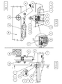
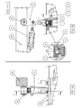
- a further characterizing element of the invention is the device for automatically positioning on a support 32 ( fig. 6B ), according to the program of the control unit, the kinematic bending mechanisms so as to rapidly, economically and safely respond to the need of reconfiguring the bending units as required with the different pitches between the wires 1 that form the sections of electro-welded mesh.
- the technical solution described hereinbelow enables the reconfiguration of the machine in the time interval from when the bent mesh panel is discharged to when a new one is loaded without requiring the intervention of the operator.
- Said mechanisms for positioning the bending pawls are fastened to the support 32 by means of a locking bracket 33 joined to the lever holding bar 28 by means of a suitable number of bolts.
- a locking bracket 33 joined to the lever holding bar 28 by means of a suitable number of bolts.
- an end of the pawl locking lever 25 characterized in having a "C" shaped cross section.
- an actuator the piston of which is connected by means of a pin to the pawl locking lever 25.
- the free end of the pawl locking lever 25 ends at the pawl release toe 24.
- the detail shown in portion AX of figure 8B illustrates the structure formed in the base of the pawls 2-1 and 2-2 in which is present a recess necessary to house the pawl locking pin 22.
- the pawl locking pins 22 are held in the idle position by the combined action of the thrust from the spring 23 and the opposing action of the stops for the pin 29; in this position the pawl locking pins 22 engage the positioning grooves 30 formed in the mobile supports 6 and 6.1.
- the bending unit shifts laterally as far as the margins of the working area so that the pawl that is to be displaced reaches the position of the pawl release mechanism.
- the actuator 27 actuates the arm 25 so that, by rotating in the direction of the arrow shown in figure 8B , the pawl release toe 24 applies a pressure on the head of the pawl locking pin 22 sufficient to force it backward and move it clear of the positioning groove 30.
- the bending unit starts to move in a direction such as to bring the bending pawl to the new position.
- the actuator 27 is manoeuvred by the control unit so that it rotates the pawl locking lever 25 by the angle necessary to relieve the pressure on the pawl locking pin 22 but, at the same time, sufficient to maintain the top part of the bending pin 2-1 or 2-2 between the two arms of the "C" described by the cross section of the pawl locking level 25. In this manner, the bending pin 2-1 or 2-2, remaining still, reaches the new position thanks to the movement of the bending unit.
- the axis of the bending pin 2-1 or 2-2 coincides with the axis in the selected positioning groove 30 and the opposing spring 23 pushes the pawl locking pin 22 to the locking position.
- the control unit thus controls the actuator 27 so that the pawl locking lever 25 reaches the idle position ( figures 8A and 8B ). This procedure is repeated for each of the pawls 2-1 and 2-2 that are to be positioned.
- the bending unit resumes the waiting position for the next section of mesh to be bent.
- the essential result of the innovation according to the invention lies in the possibility of using, for shaping electro-welded meshes, a plurality of mobile bending-pin supports and a corresponding plurality of bending arms that together form individual bending units independent of each other.
- the machine according to the invention makes it possible to drastically reduce the bending times of the electro-welded meshes, as it is possible to operate the bending units in the most selective manner, that is, individually or in groups.
Landscapes
- Engineering & Computer Science (AREA)
- Architecture (AREA)
- Mechanical Engineering (AREA)
- Civil Engineering (AREA)
- Structural Engineering (AREA)
- Wire Processing (AREA)
- Bending Of Plates, Rods, And Pipes (AREA)
- Closing Of Containers (AREA)
- Shaping Of Tube Ends By Bending Or Straightening (AREA)
Claims (7)
- Automatische Maschine zum Biegen elektrisch verschweißter Gitter, die aus Längs- und Quer-Drähten (1) bestehen, unterschiedliche Längen und/oder unterschiedliche Abstände haben, wobei die Maschine wenigstens eine Biege-Einheit (U) aufweist, die mit einer Vielzahl von Biege-Bolzen (2, 2-1, 2-2) versehen ist, die in vertikaler Richtung betätigt werden, und die Biege-Bolzen so eingerichtet sind, dass sie in einem Abstand verteilt sind, der der Teilung des zu biegenden Gitters (R) entspricht, und eine Vielzahl von Biege-Armen (3, 4, 4-1) mit einer Zwei-Achsen-Bewegung betätigt werden, um die Drähte um die Biege-Bolzen herum zu biegen, wobei die Biege-Einheit (U) an dem Hauptkörper (10) der Maschine angebracht ist und in der Lage ist, sich in einer Richtung quer zu der Richtung zu bewegen, in der sich das Gitter (R) bewegt, und die Biege-Einheit (U) auch in der Lage ist, sich um ihre vertikale Achse (W) herum zu drehen,
dadurch gekennzeichnet, dass die Biege-Bolzen (2, 2-1, 2-2) mittels ihrer jeweiligen Betätigungselemente (8) betätigt werden, die in der Biege-Einheit (U) aufgenommen sind und die so eingerichtet sind, dass sie entsprechend einem vorgegebenen Programm über eine Steuereinheit selektiv und unabhängig angesteuert werden, und die Biege-Arme (3, 4, 4-1) mit der Biege-Einheit (U) über einen gelenkigen kinematischen Mechanismus (11-13, 16-19) verbunden sind und so eingerichtet sind, dass sie entsprechend dem vorgegebenen Programm über die Steuereinheit selektiv und unabhängig so angetrieben werden, dass sie die jeweiligen Biege-Bolzen abdecken. - Automatische Maschine zum Biegen elektrisch verschweißter Metallgitter nach Anspruch 1, dadurch gekennzeichnet, dass die Betätigungselemente (8) dazu geeignet sind, die Biege-Bolzen in einer vertikalen Richtung (2-1, 2-2) über entsprechende Lager (5, 6, 6-1) zu betätigen, die durch Führungen (7) in Position gehalten werden, wobei die vertikale Verschiebung so reguliert wird, dass sich die Biege-Bolzen (2, 2-1, 2-2) über die Bearbeitungsfläche anheben.
- Automatische Maschine zum Biegen elektrisch verschweißter Metallgitter nach Anspruch 1, dadurch gekennzeichnet, dass der gelenkige kinematische Mechanismus mit einem Betätigungselement (11) versehen ist, dessen Welle (13) über eine Kurbel (12) eine Verbindungsstange (16) betätigt, die schwenkbar mit einem entgegenwirkenden Arm (17) verbunden ist, der an der Biege-Einheit (U) angelenkt ist.
- Automatische Maschine zum Biegen elektrisch verschweißter Metallgitter nach Anspruch 3, dadurch gekennzeichnet, dass jede Kurbel (12) über einen Verbindungsbolzen (14), der mittels einer Wähleinrichtung (15) betätigt wird, integral mit der Welle (13) verbunden ist.
- Automatische Maschine zum Biegen elektrisch verschweißter Metallgitter nach Anspruch 3, dadurch gekennzeichnet, dass ein Bolzen (18) dazu geeignet ist, die Drehung der Kurbelwelle und der Verbindungsstange (16) zueinander zuzulassen, während ein Drehzapfen (19) dazu geeignet ist, die Drehung der Verbindungsstange (16) und des entgegenwirkenden Arms (17) zu zuzulassen.
- Automatische Maschine zum Biegen elektrisch verschweißter Metallgitter nach Anspruch 2, dadurch gekennzeichnet, dass die Lager (6, 6-1), die die Biege-Bolzen (2-1, 2-2) aufnehmen, an ihrer Oberseite mit Positioniernuten (30) versehen sind, in denen eine Vielzahl selektiv in Eingriff kommender Halte-Bolzen (22) von Federn geführt werden und an ihren jeweiligen Biege-Bolzen (2-1, 2-2) eingehakt werden, wobei die Halte-Bolzen (22) durch jeweilige motorgetriebene Arme (24-27) betätigt werden, die an einer Halteschiene (28) angelenkt sind, die an dem Hauptkörper (10) der Maschine angebracht sind.
- Automatische Maschine zum Biegen elektrisch verschweißter Metallgitter nach Anspruch 1, gekennzeichnet durch die Tatsache, dass zwei Biege-Einheiten (U1, U2) vorhanden sind, die an einem Träger (P) angebracht sind, der über der Längsachse des Gitters (R) liegt und auf zwei Schienen (G) bewegt werden kann, die von dem Körper (10) der Maschine gehalten werden, wobei die Schienen (G) auf beiden Seiten des Gitters (R) und in der gleichen Richtung wie die Längsachse des Gitters (R) verlaufen.
Priority Applications (4)
| Application Number | Priority Date | Filing Date | Title |
|---|---|---|---|
| HRP20161592TT HRP20161592T1 (hr) | 2012-11-19 | 2013-11-04 | Uređaj za automatsko savijanje elektro-zavarenih mreža |
| PL13801809T PL2919928T3 (pl) | 2012-11-19 | 2013-11-04 | Maszyna automatyczna do gięcia spawanych elektrycznie siatek |
| SI201330431A SI2919928T1 (sl) | 2012-11-19 | 2013-11-04 | Avtomatski stroj za krivljenje elektrovarjenih mrež |
| RS20161072A RS55407B1 (sr) | 2012-11-19 | 2013-11-04 | Automatska mašina za savijanje elektro-zavarenih mreža |
Applications Claiming Priority (2)
| Application Number | Priority Date | Filing Date | Title |
|---|---|---|---|
| IT000069A ITPN20120069A1 (it) | 2012-11-19 | 2012-11-19 | Macchina automatica piegatrice di reti elettrosaldate |
| PCT/IB2013/059881 WO2014076605A1 (en) | 2012-11-19 | 2013-11-04 | Automatic machine to bend electro-welded meshes |
Publications (2)
| Publication Number | Publication Date |
|---|---|
| EP2919928A1 EP2919928A1 (de) | 2015-09-23 |
| EP2919928B1 true EP2919928B1 (de) | 2016-09-21 |
Family
ID=47633292
Family Applications (1)
| Application Number | Title | Priority Date | Filing Date |
|---|---|---|---|
| EP13801809.8A Active EP2919928B1 (de) | 2012-11-19 | 2013-11-04 | Automatische maschine zum biegen von elektrogeschweissten geflechten |
Country Status (15)
| Country | Link |
|---|---|
| EP (1) | EP2919928B1 (de) |
| BR (1) | BR112015009594A2 (de) |
| DK (1) | DK2919928T3 (de) |
| ES (1) | ES2607810T3 (de) |
| HR (1) | HRP20161592T1 (de) |
| IN (1) | IN2015KN00597A (de) |
| IT (1) | ITPN20120069A1 (de) |
| LT (1) | LT2919928T (de) |
| PL (1) | PL2919928T3 (de) |
| PT (1) | PT2919928T (de) |
| RS (1) | RS55407B1 (de) |
| RU (1) | RU2620316C2 (de) |
| SI (1) | SI2919928T1 (de) |
| SM (1) | SMT201600420B (de) |
| WO (1) | WO2014076605A1 (de) |
Families Citing this family (6)
| Publication number | Priority date | Publication date | Assignee | Title |
|---|---|---|---|---|
| CN110091175B (zh) * | 2019-06-12 | 2021-01-22 | 江苏科技大学 | 一种方桩端板折弯焊接一体成型装置 |
| CN110576092B (zh) * | 2019-10-21 | 2021-03-05 | 北京建筑机械化研究院有限公司 | 一种钢筋网片弯折设备 |
| CN113441890B (zh) * | 2020-03-24 | 2023-09-12 | 广东博智林机器人有限公司 | 一种双层网焊接生产线 |
| CN113618268B (zh) * | 2021-10-13 | 2021-12-07 | 启东辉煌钢结构工程有限公司 | 一种钢结构全自动焊接设备 |
| CN114505384B (zh) * | 2022-03-17 | 2023-05-09 | 宁波交通工程建设集团有限公司 | 一种钢筋骨架双向定位弯折机 |
| CN119772064B (zh) * | 2025-01-20 | 2025-11-18 | 河北骄阳焊工有限公司 | 波浪丝网片焊接线用波浪丝折弯送丝机构及用该装置折弯送丝的方法 |
Family Cites Families (6)
| Publication number | Priority date | Publication date | Assignee | Title |
|---|---|---|---|---|
| DE2237895C3 (de) * | 1972-08-02 | 1974-11-28 | Rudolf 7031 Holzgerlingen Bock | Einrichtung zum Abwinkein von Baustahlmatten |
| JPS5135776A (ja) * | 1974-09-20 | 1976-03-26 | Nippon Steel Corp | Yosetsunyorukanaaminoseizohoho |
| SU574253A1 (ru) * | 1976-02-19 | 1977-09-30 | Трест По Производству Строительных Материалов И Строительных Изделий "Промстройматериалы" | Станок дл гибки арматурных сеток |
| SU664715A1 (ru) * | 1977-04-26 | 1979-05-30 | Опытное производственно-техническое предприятие "Энерготехпром" | Устройство дл гибки арматурной сетки |
| FR2721640B1 (fr) * | 1994-06-28 | 1996-09-13 | Bokobza Galdys | Procédé de fabrication d'armatures pour béton armé. |
| ATE450327T1 (de) * | 2007-04-02 | 2009-12-15 | Ruwa Drahtschweisswerk Ag | Verfahren und vorrichtung zur herstellung eines bewehrungskorbs aus einer baustahlmatte |
-
2012
- 2012-11-19 IT IT000069A patent/ITPN20120069A1/it unknown
-
2013
- 2013-11-04 WO PCT/IB2013/059881 patent/WO2014076605A1/en not_active Ceased
- 2013-11-04 HR HRP20161592TT patent/HRP20161592T1/hr unknown
- 2013-11-04 RS RS20161072A patent/RS55407B1/sr unknown
- 2013-11-04 PT PT138018098T patent/PT2919928T/pt unknown
- 2013-11-04 SI SI201330431A patent/SI2919928T1/sl unknown
- 2013-11-04 EP EP13801809.8A patent/EP2919928B1/de active Active
- 2013-11-04 LT LTEP13801809.8T patent/LT2919928T/lt unknown
- 2013-11-04 PL PL13801809T patent/PL2919928T3/pl unknown
- 2013-11-04 RU RU2015123291A patent/RU2620316C2/ru not_active IP Right Cessation
- 2013-11-04 ES ES13801809.8T patent/ES2607810T3/es active Active
- 2013-11-04 BR BR112015009594A patent/BR112015009594A2/pt not_active Application Discontinuation
- 2013-11-04 DK DK13801809.8T patent/DK2919928T3/da active
-
2015
- 2015-03-09 IN IN597KON2015 patent/IN2015KN00597A/en unknown
-
2016
- 2016-11-18 SM SM201600420T patent/SMT201600420B/it unknown
Also Published As
| Publication number | Publication date |
|---|---|
| RS55407B1 (sr) | 2017-04-28 |
| HRP20161592T1 (hr) | 2017-01-13 |
| SMT201600420B (it) | 2017-01-10 |
| ITPN20120069A1 (it) | 2014-05-20 |
| RU2015123291A (ru) | 2017-01-10 |
| RU2620316C2 (ru) | 2017-05-24 |
| DK2919928T3 (da) | 2017-01-02 |
| PT2919928T (pt) | 2016-12-02 |
| BR112015009594A2 (pt) | 2017-07-04 |
| SI2919928T1 (sl) | 2017-01-31 |
| WO2014076605A1 (en) | 2014-05-22 |
| ES2607810T3 (es) | 2017-04-04 |
| EP2919928A1 (de) | 2015-09-23 |
| PL2919928T3 (pl) | 2017-05-31 |
| IN2015KN00597A (de) | 2015-07-17 |
| LT2919928T (lt) | 2017-02-27 |
Similar Documents
| Publication | Publication Date | Title |
|---|---|---|
| EP2919928B1 (de) | Automatische maschine zum biegen von elektrogeschweissten geflechten | |
| EP3941656B1 (de) | Montagemaschine und verfahren zur herstellung von bewehrungsstrukturen | |
| KR102151090B1 (ko) | 철근 밴딩기 | |
| US20180236527A1 (en) | Portable, Compact and Automated Cage Making Machine | |
| JP2020076256A (ja) | 鉄筋結束用自走ロボット | |
| DK180301B1 (en) | Assembly machine and method for manufacturing reinforcement structures | |
| SU1279519A3 (ru) | Машина дл контактной точечной сварки решеток | |
| CN203209581U (zh) | 用于钢筋一次成型的自动成型机 | |
| DK2736692T3 (en) | Production plant comprising a transport system for processing extended products, especially wind turbine blades, with extended mold assemblies | |
| CN113059093B (zh) | 钢筋笼生产装置 | |
| CN103170554B (zh) | 用于钢筋一次成型的自动成型机 | |
| US8820134B2 (en) | Mechanism for moving the blade holder of a panel bender for bending sheet metal | |
| JP5937133B2 (ja) | 電線布設装置 | |
| US20150209856A1 (en) | Bending Machine For Wire Mesh Mats | |
| EP3715007A1 (de) | Automatische biegeeinheit für metalldrahtelemente von elektrogeschweissten gittern und zugehöriges biegeverfahren | |
| CN113677449A (zh) | 棒材加工机器及相应加工方法 | |
| KR900000317B1 (ko) | 조립식 건축부재용 입체철망구조물 제작방법과 그 장치 | |
| CN120421889B (zh) | 一种混凝土预构件生产用焊接装置 | |
| WO1995005906A1 (en) | Method and machines for the production of product consisting of two parallel steel wire-meshes and intermediate panel of insulating material | |
| CN103100610B (zh) | 一种杆式钢筋自动成型机 | |
| WO2014108535A1 (en) | Strand guide system | |
| CN105618969A (zh) | 钢筋骨架截面尺寸调节装置 | |
| EP3790686B1 (de) | Verfahren und vorrichtung zur herstellung von abstandshalterstrukturen | |
| CN218092105U (zh) | 钢筋排布机构及钢筋排布装置 | |
| KR102886823B1 (ko) | 용접철근매트 벤딩장치 |
Legal Events
| Date | Code | Title | Description |
|---|---|---|---|
| PUAI | Public reference made under article 153(3) epc to a published international application that has entered the european phase |
Free format text: ORIGINAL CODE: 0009012 |
|
| 17P | Request for examination filed |
Effective date: 20150520 |
|
| AK | Designated contracting states |
Kind code of ref document: A1 Designated state(s): AL AT BE BG CH CY CZ DE DK EE ES FI FR GB GR HR HU IE IS IT LI LT LU LV MC MK MT NL NO PL PT RO RS SE SI SK SM TR |
|
| AX | Request for extension of the european patent |
Extension state: BA ME |
|
| DAX | Request for extension of the european patent (deleted) | ||
| GRAP | Despatch of communication of intention to grant a patent |
Free format text: ORIGINAL CODE: EPIDOSNIGR1 |
|
| INTG | Intention to grant announced |
Effective date: 20160622 |
|
| GRAS | Grant fee paid |
Free format text: ORIGINAL CODE: EPIDOSNIGR3 |
|
| GRAA | (expected) grant |
Free format text: ORIGINAL CODE: 0009210 |
|
| AK | Designated contracting states |
Kind code of ref document: B1 Designated state(s): AL AT BE BG CH CY CZ DE DK EE ES FI FR GB GR HR HU IE IS IT LI LT LU LV MC MK MT NL NO PL PT RO RS SE SI SK SM TR |
|
| REG | Reference to a national code |
Ref country code: GB Ref legal event code: FG4D |
|
| REG | Reference to a national code |
Ref country code: CH Ref legal event code: EP |
|
| REG | Reference to a national code |
Ref country code: AT Ref legal event code: REF Ref document number: 830625 Country of ref document: AT Kind code of ref document: T Effective date: 20161015 |
|
| REG | Reference to a national code |
Ref country code: IE Ref legal event code: FG4D |
|
| REG | Reference to a national code |
Ref country code: DE Ref legal event code: R096 Ref document number: 602013011981 Country of ref document: DE |
|
| REG | Reference to a national code |
Ref country code: FR Ref legal event code: PLFP Year of fee payment: 4 |
|
| REG | Reference to a national code |
Ref country code: HR Ref legal event code: TUEP Ref document number: P20161592 Country of ref document: HR Ref country code: CH Ref legal event code: NV Representative=s name: PATENTANWAELTE SCHAAD, BALASS, MENZL AND PARTN, CH |
|
| REG | Reference to a national code |
Ref country code: PT Ref legal event code: SC4A Ref document number: 2919928 Country of ref document: PT Date of ref document: 20161202 Kind code of ref document: T Free format text: AVAILABILITY OF NATIONAL TRANSLATION Effective date: 20161125 |
|
| REG | Reference to a national code |
Ref country code: NL Ref legal event code: FP |
|
| REG | Reference to a national code |
Ref country code: RO Ref legal event code: EPE |
|
| REG | Reference to a national code |
Ref country code: SE Ref legal event code: TRGR |
|
| REG | Reference to a national code |
Ref country code: DK Ref legal event code: T3 Effective date: 20161227 |
|
| REG | Reference to a national code |
Ref country code: HR Ref legal event code: T1PR Ref document number: P20161592 Country of ref document: HR |
|
| REG | Reference to a national code |
Ref country code: NO Ref legal event code: T2 Effective date: 20160921 |
|
| REG | Reference to a national code |
Ref country code: EE Ref legal event code: FG4A Ref document number: E013157 Country of ref document: EE Effective date: 20161206 |
|
| REG | Reference to a national code |
Ref country code: SK Ref legal event code: T3 Ref document number: E 22734 Country of ref document: SK |
|
| PG25 | Lapsed in a contracting state [announced via postgrant information from national office to epo] |
Ref country code: IS Free format text: LAPSE BECAUSE OF FAILURE TO SUBMIT A TRANSLATION OF THE DESCRIPTION OR TO PAY THE FEE WITHIN THE PRESCRIBED TIME-LIMIT Effective date: 20170121 |
|
| REG | Reference to a national code |
Ref country code: DE Ref legal event code: R097 Ref document number: 602013011981 Country of ref document: DE |
|
| REG | Reference to a national code |
Ref country code: GR Ref legal event code: EP Ref document number: 20160402923 Country of ref document: GR Effective date: 20170410 |
|
| PLBE | No opposition filed within time limit |
Free format text: ORIGINAL CODE: 0009261 |
|
| STAA | Information on the status of an ep patent application or granted ep patent |
Free format text: STATUS: NO OPPOSITION FILED WITHIN TIME LIMIT |
|
| 26N | No opposition filed |
Effective date: 20170622 |
|
| PG25 | Lapsed in a contracting state [announced via postgrant information from national office to epo] |
Ref country code: LU Free format text: LAPSE BECAUSE OF NON-PAYMENT OF DUE FEES Effective date: 20161130 |
|
| REG | Reference to a national code |
Ref country code: FR Ref legal event code: PLFP Year of fee payment: 5 |
|
| PG25 | Lapsed in a contracting state [announced via postgrant information from national office to epo] |
Ref country code: HU Free format text: LAPSE BECAUSE OF FAILURE TO SUBMIT A TRANSLATION OF THE DESCRIPTION OR TO PAY THE FEE WITHIN THE PRESCRIBED TIME-LIMIT; INVALID AB INITIO Effective date: 20131104 |
|
| PG25 | Lapsed in a contracting state [announced via postgrant information from national office to epo] |
Ref country code: MC Free format text: LAPSE BECAUSE OF FAILURE TO SUBMIT A TRANSLATION OF THE DESCRIPTION OR TO PAY THE FEE WITHIN THE PRESCRIBED TIME-LIMIT Effective date: 20160921 Ref country code: CY Free format text: LAPSE BECAUSE OF FAILURE TO SUBMIT A TRANSLATION OF THE DESCRIPTION OR TO PAY THE FEE WITHIN THE PRESCRIBED TIME-LIMIT Effective date: 20160921 |
|
| PGFP | Annual fee paid to national office [announced via postgrant information from national office to epo] |
Ref country code: MT Payment date: 20171023 Year of fee payment: 5 |
|
| PG25 | Lapsed in a contracting state [announced via postgrant information from national office to epo] |
Ref country code: AL Free format text: LAPSE BECAUSE OF FAILURE TO SUBMIT A TRANSLATION OF THE DESCRIPTION OR TO PAY THE FEE WITHIN THE PRESCRIBED TIME-LIMIT Effective date: 20160921 |
|
| REG | Reference to a national code |
Ref country code: HR Ref legal event code: ODRP Ref document number: P20161592 Country of ref document: HR Payment date: 20181024 Year of fee payment: 6 |
|
| PGFP | Annual fee paid to national office [announced via postgrant information from national office to epo] |
Ref country code: GB Payment date: 20181120 Year of fee payment: 9 Ref country code: DK Payment date: 20181122 Year of fee payment: 6 Ref country code: PT Payment date: 20181022 Year of fee payment: 6 Ref country code: IE Payment date: 20181123 Year of fee payment: 6 Ref country code: RO Payment date: 20181024 Year of fee payment: 6 Ref country code: CZ Payment date: 20181023 Year of fee payment: 6 Ref country code: EE Payment date: 20181116 Year of fee payment: 6 Ref country code: GR Payment date: 20181113 Year of fee payment: 6 Ref country code: SK Payment date: 20181023 Year of fee payment: 6 Ref country code: PL Payment date: 20181023 Year of fee payment: 6 Ref country code: FI Payment date: 20181121 Year of fee payment: 6 Ref country code: SE Payment date: 20181120 Year of fee payment: 6 |
|
| PGFP | Annual fee paid to national office [announced via postgrant information from national office to epo] |
Ref country code: BG Payment date: 20181122 Year of fee payment: 6 Ref country code: TR Payment date: 20181025 Year of fee payment: 6 Ref country code: ES Payment date: 20181218 Year of fee payment: 6 Ref country code: BE Payment date: 20181120 Year of fee payment: 6 Ref country code: SI Payment date: 20181019 Year of fee payment: 6 Ref country code: SM Payment date: 20181127 Year of fee payment: 6 Ref country code: RS Payment date: 20181025 Year of fee payment: 6 Ref country code: FR Payment date: 20181123 Year of fee payment: 6 |
|
| REG | Reference to a national code |
Ref country code: AT Ref legal event code: UEP Ref document number: 830625 Country of ref document: AT Kind code of ref document: T Effective date: 20160921 |
|
| PGFP | Annual fee paid to national office [announced via postgrant information from national office to epo] |
Ref country code: MK Payment date: 20181026 Year of fee payment: 6 |
|
| REG | Reference to a national code |
Ref country code: HR Ref legal event code: PBON Ref document number: P20161592 Country of ref document: HR Effective date: 20191104 |
|
| REG | Reference to a national code |
Ref country code: FI Ref legal event code: MAE |
|
| REG | Reference to a national code |
Ref country code: EE Ref legal event code: MM4A Ref document number: E013157 Country of ref document: EE Effective date: 20191130 |
|
| REG | Reference to a national code |
Ref country code: DK Ref legal event code: EBP Effective date: 20191130 Ref country code: NO Ref legal event code: MMEP |
|
| REG | Reference to a national code |
Ref country code: SE Ref legal event code: EUG |
|
| PG25 | Lapsed in a contracting state [announced via postgrant information from national office to epo] |
Ref country code: RO Free format text: LAPSE BECAUSE OF NON-PAYMENT OF DUE FEES Effective date: 20191104 Ref country code: FI Free format text: LAPSE BECAUSE OF NON-PAYMENT OF DUE FEES Effective date: 20191104 Ref country code: NO Free format text: LAPSE BECAUSE OF NON-PAYMENT OF DUE FEES Effective date: 20191130 Ref country code: RS Free format text: LAPSE BECAUSE OF NON-PAYMENT OF DUE FEES Effective date: 20191104 Ref country code: GR Free format text: LAPSE BECAUSE OF NON-PAYMENT OF DUE FEES Effective date: 20200609 Ref country code: EE Free format text: LAPSE BECAUSE OF NON-PAYMENT OF DUE FEES Effective date: 20191130 Ref country code: PT Free format text: LAPSE BECAUSE OF NON-PAYMENT OF DUE FEES Effective date: 20200604 Ref country code: CZ Free format text: LAPSE BECAUSE OF NON-PAYMENT OF DUE FEES Effective date: 20191104 |
|
| REG | Reference to a national code |
Ref country code: SK Ref legal event code: MM4A Ref document number: E 22734 Country of ref document: SK Effective date: 20191104 |
|
| REG | Reference to a national code |
Ref country code: LT Ref legal event code: MM4D Effective date: 20191104 |
|
| REG | Reference to a national code |
Ref country code: BE Ref legal event code: MM Effective date: 20191130 |
|
| PG25 | Lapsed in a contracting state [announced via postgrant information from national office to epo] |
Ref country code: LV Free format text: LAPSE BECAUSE OF NON-PAYMENT OF DUE FEES Effective date: 20191104 Ref country code: SE Free format text: LAPSE BECAUSE OF NON-PAYMENT OF DUE FEES Effective date: 20191105 Ref country code: HR Free format text: LAPSE BECAUSE OF NON-PAYMENT OF DUE FEES Effective date: 20191104 Ref country code: MT Free format text: LAPSE BECAUSE OF NON-PAYMENT OF DUE FEES Effective date: 20181104 Ref country code: BG Free format text: LAPSE BECAUSE OF NON-PAYMENT OF DUE FEES Effective date: 20200531 Ref country code: SM Free format text: LAPSE BECAUSE OF NON-PAYMENT OF DUE FEES Effective date: 20200602 Ref country code: SK Free format text: LAPSE BECAUSE OF NON-PAYMENT OF DUE FEES Effective date: 20191104 |
|
| GBPC | Gb: european patent ceased through non-payment of renewal fee |
Effective date: 20191104 |
|
| PG25 | Lapsed in a contracting state [announced via postgrant information from national office to epo] |
Ref country code: IE Free format text: LAPSE BECAUSE OF NON-PAYMENT OF DUE FEES Effective date: 20191104 Ref country code: FR Free format text: LAPSE BECAUSE OF NON-PAYMENT OF DUE FEES Effective date: 20191130 Ref country code: DK Free format text: LAPSE BECAUSE OF NON-PAYMENT OF DUE FEES Effective date: 20191130 Ref country code: GB Free format text: LAPSE BECAUSE OF NON-PAYMENT OF DUE FEES Effective date: 20191104 Ref country code: LT Free format text: LAPSE BECAUSE OF NON-PAYMENT OF DUE FEES Effective date: 20191104 |
|
| PG25 | Lapsed in a contracting state [announced via postgrant information from national office to epo] |
Ref country code: BE Free format text: LAPSE BECAUSE OF NON-PAYMENT OF DUE FEES Effective date: 20191130 Ref country code: SI Free format text: LAPSE BECAUSE OF NON-PAYMENT OF DUE FEES Effective date: 20191105 |
|
| REG | Reference to a national code |
Ref country code: SI Ref legal event code: KO00 Effective date: 20201030 |
|
| REG | Reference to a national code |
Ref country code: ES Ref legal event code: FD2A Effective date: 20210527 |
|
| PG25 | Lapsed in a contracting state [announced via postgrant information from national office to epo] |
Ref country code: ES Free format text: LAPSE BECAUSE OF NON-PAYMENT OF DUE FEES Effective date: 20191105 |
|
| PG25 | Lapsed in a contracting state [announced via postgrant information from national office to epo] |
Ref country code: PL Free format text: LAPSE BECAUSE OF NON-PAYMENT OF DUE FEES Effective date: 20191104 |
|
| PG25 | Lapsed in a contracting state [announced via postgrant information from national office to epo] |
Ref country code: TR Free format text: LAPSE BECAUSE OF NON-PAYMENT OF DUE FEES Effective date: 20191104 |
|
| REG | Reference to a national code |
Ref country code: DE Ref legal event code: R081 Ref document number: 602013011981 Country of ref document: DE Owner name: AWM SRL, MAGNANO IN RIVIERA, IT Free format text: FORMER OWNER: A.W.M. S.P.A., MAGNANO IN RIVIERA, UDINE, IT Ref country code: DE Ref legal event code: R082 Ref document number: 602013011981 Country of ref document: DE Representative=s name: REHBERG HUEPPE + PARTNER PATENTANWAELTE PARTG , DE |
|
| REG | Reference to a national code |
Ref country code: AT Ref legal event code: PC Ref document number: 830625 Country of ref document: AT Kind code of ref document: T Owner name: AWM SRL, IT Effective date: 20230320 |
|
| P01 | Opt-out of the competence of the unified patent court (upc) registered |
Effective date: 20230313 |
|
| REG | Reference to a national code |
Ref country code: NL Ref legal event code: PD Owner name: AWM SRL; IT Free format text: DETAILS ASSIGNMENT: CHANGE OF OWNER(S), DEMERGER; FORMER OWNER NAME: SIBLINGS. S.P.A Effective date: 20230710 Ref country code: NL Ref legal event code: HC Owner name: SIBLINGS. S.P.A; IT Free format text: DETAILS ASSIGNMENT: CHANGE OF OWNER(S), CHANGE OF OWNER(S) NAME; FORMER OWNER NAME: A.W.M. S.P.A. Effective date: 20230710 |
|
| REG | Reference to a national code |
Ref country code: CH Ref legal event code: U11 Free format text: ST27 STATUS EVENT CODE: U-0-0-U10-U11 (AS PROVIDED BY THE NATIONAL OFFICE) Effective date: 20251202 |
|
| PGFP | Annual fee paid to national office [announced via postgrant information from national office to epo] |
Ref country code: DE Payment date: 20251223 Year of fee payment: 13 |
|
| PGFP | Annual fee paid to national office [announced via postgrant information from national office to epo] |
Ref country code: AT Payment date: 20251128 Year of fee payment: 13 |
|
| PGFP | Annual fee paid to national office [announced via postgrant information from national office to epo] |
Ref country code: IT Payment date: 20251201 Year of fee payment: 13 |
|
| PGFP | Annual fee paid to national office [announced via postgrant information from national office to epo] |
Ref country code: NL Payment date: 20251128 Year of fee payment: 13 |
|
| PGFP | Annual fee paid to national office [announced via postgrant information from national office to epo] |
Ref country code: CH Payment date: 20251202 Year of fee payment: 13 |