EP3790686B1 - Verfahren und vorrichtung zur herstellung von abstandshalterstrukturen - Google Patents
Verfahren und vorrichtung zur herstellung von abstandshalterstrukturen Download PDFInfo
- Publication number
- EP3790686B1 EP3790686B1 EP19729861.5A EP19729861A EP3790686B1 EP 3790686 B1 EP3790686 B1 EP 3790686B1 EP 19729861 A EP19729861 A EP 19729861A EP 3790686 B1 EP3790686 B1 EP 3790686B1
- Authority
- EP
- European Patent Office
- Prior art keywords
- assembly
- transversal
- supply
- longitudinal
- joining
- Prior art date
- Legal status (The legal status is an assumption and is not a legal conclusion. Google has not performed a legal analysis and makes no representation as to the accuracy of the status listed.)
- Active
Links
Images



Classifications
-
- B—PERFORMING OPERATIONS; TRANSPORTING
- B21—MECHANICAL METAL-WORKING WITHOUT ESSENTIALLY REMOVING MATERIAL; PUNCHING METAL
- B21F—WORKING OR PROCESSING OF METAL WIRE
- B21F27/00—Making wire network, i.e. wire nets
- B21F27/12—Making special types or portions of network by methods or means specially adapted therefor
- B21F27/20—Making special types or portions of network by methods or means specially adapted therefor of plaster-carrying network
-
- B—PERFORMING OPERATIONS; TRANSPORTING
- B21—MECHANICAL METAL-WORKING WITHOUT ESSENTIALLY REMOVING MATERIAL; PUNCHING METAL
- B21F—WORKING OR PROCESSING OF METAL WIRE
- B21F27/00—Making wire network, i.e. wire nets
- B21F27/08—Making wire network, i.e. wire nets with additional connecting elements or material at crossings
- B21F27/10—Making wire network, i.e. wire nets with additional connecting elements or material at crossings with soldered or welded crossings
Definitions
- the present invention relates to a method and an apparatus for making spacer structures, in particular spacer structures for reinforced concrete constructions.
- spacer structures intended for use as spacer elements to define the distance between building components, suitable to realize the reinforcement of reinforced concrete constructions, is known and widespread.
- spacer structures are used in the construction of prefabricated elements or floors, to space apart different reticular reinforcing layers, before casting the concrete.
- These structures are shaped as a ladder or trellis, being constituted by at least one pair of, more commonly, three or four, parallel longitudinal elements suitably spaced, joined, preferably by electro-welding, to a plurality of transversal elements, generally of reduced length compared to the longitudinal elements, arranged parallel and suitably spaced.
- Patent application EP 0715923 illustrates a welding apparatus for making metal meshes, comprising elements for supplying longitudinal metal wires and an element for supplying transversal metal wires, as well as cutting means for separating the meshes made.
- the object of the present invention is to solve said drawbacks by devising a method and an apparatus to make spacer structures, which allows to realize such structures in an effective, versatile manner.
- the method for making spacer structures provides for arranging at least one first supply assembly for the longitudinal elements along a longitudinal direction and a second supply assembly for the same longitudinal elements, an insertion assembly configured to insert at least one transversal element at a time along a transversal direction in an insertion channel, a cutting assembly associated with the aforesaid insertion assembly, acting in correspondence with a cutting plane transversal to the aforesaid transversal insertion direction, a joining assembly for joining, preferably by electro-welding, the longitudinal elements supplied to the transversal elements.
- the first supply assembly and the second supply assembly each comprise at least one supply device configured to feed at least one longitudinal element at a time along the aforesaid longitudinal direction.
- the method provides moving at least one of the first supply assembly and the second supply assembly along the aforementioned transversal direction between an operating area, within which the joining of the longitudinal elements can take place with the transversal elements fed from time to time, by means of the joining assembly, and at least one drop-off area, arranged externally to the aforesaid operating area, laterally thereof, in which it is possible to carry out further operations simultaneously, for example for setting the present supply devices, in particular changing the supplied longitudinal element, replacing the welding electrodes, maintenance.
- first supply assembly and/or the second supply assembly are associated with moving means to be movable along the aforesaid transversal direction, for example actuating means of a known type.
- the aforesaid drop-off area is substantially delimited by the aforementioned cutting plane and opposed to the aforesaid channel for the insertion of the transversal elements disposed in the aforementioned operating area.
- the drop-off area serves to house at least one feeding unit for the longitudinal elements, in order to be able to perform several operations simultaneously during the same production cycle: for example, the replacement of the longitudinal elements in a supply assembly that is stationary in the drop-off area, and the execution of a spacer structure in the operating area by the remaining supply assembly of the longitudinal elements. All the operations described can take place in complete safety in the aforementioned drop-off area while the other supply assembly is engaged in normal production in the operating area.
- the at least one drop-off area is arranged, preferably, outside the area in which the positioning of the transversal elements can occur, so as not to obstruct the operating area in any way.
- the aforementioned drop-off area represents an area in which at least one supply assembly can operate an extra-stroke in the aforesaid transversal direction and remain stationary, to be arranged, meanwhile, for a subsequent work cycle.
- the method and the apparatus according to the invention allow to easily change, within the same production cycle, the type of element or longitudinal elements suitable to form a spacer structure to be produced.
- the method and the apparatus according to the invention allow this replacement to be carried out while the production of at least one spacer structure in correspondence with the aforementioned operating area is in progress, considerably increasing the production efficiency.
- a further assembly for the insertion of the transversal elements opposite to the aforementioned insertion assembly, on the opposite side with respect to the insertion channel.
- the presence of a further insertion assembly allows transversal elements to be inserted in the insertion channel both in one direction and in the direction opposite to the aforesaid transversal direction.
- the apparatus according to the invention can provide at least one assembly for joining the longitudinal elements to the transversal elements, sliding in a transversal direction, preferably in an automated way to carry out the respective positioning operations in an appropriate manner.
- the aforesaid joining assembly preferably by welding, cooperates with a pulling unit for the longitudinal elements supplied from time to time, which can be activated independently on the element itself.
- the same joining assembly cooperates with a winding gear member, provided by the respective supply device, which can be tilted with respect to the longitudinal direction of feeding of the longitudinal elements, configured to reduce the dynamic reactions to which each longitudinal element is subjected during the joining steps.
- each supply device of the first supply assembly or, respectively, of the second supply assembly of the longitudinal elements is associated with a joining unit of the joining assembly.
- each joining unit is preferably integrally associated with the respective supply device of the longitudinal elements, so as to follow the movements of the latter when it is necessary to change the format of the spacer structure to be made and therefore reduce the number of adjustments to be made.
- the method and the apparatus according to the invention provide inserting the transversal elements below the longitudinal elements provided, so as to maintain the reciprocal plane of tangency unchanged even when at the varying of the type, in particular the transversal dimensions, of the longitudinal elements supplied.
- the positioning of at least one cutting assembly provided and therefore of the corresponding cutting plane can be advantageously adjustable in the transversal direction between a position approached to the insertion channel, and therefore to the operating area, and a position apart from the same insertion channel, therefore from the same operating area.
- the possibility of adjusting the transversal positioning of the cutting assembly allows, in particular, to provide spacer structures without protrusion of the transversal elements with respect to the longitudinal element to which they are joined, or with a protrusion of controlled extension.
- the control of the extension of this protrusion is important since it determines, locally, the amount of the cover therefore the protection of the reinforcement against external corrosion agents and also the acoustic transmission of the final product.
- the apparatus according to the invention is indicated with 1, for making spacer structures 2, by joining at least one pair of longitudinal elements 3, arranged parallel and suitably spaced, to at least one transversal element 4.
- longitudinal element 3 and transversal element 4 are preferably meant metal wires, intended to be arranged longitudinally or transversely in a spacer structure 2.
- a spacer structure 2 comprising at least one pair of transversal elements 4 which, like the longitudinal elements 3, are also arranged appropriately spaced and, preferably, perpendicularly to the aforesaid longitudinal elements 3.
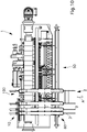
- the apparatus 1 comprises at least a first supply assembly 10 of the longitudinal elements 3, along a longitudinal direction A, at least a second supply assembly 100 of the longitudinal elements 3, an insertion assembly 20 of the transversal elements 4, along a transversal direction B, a cutting assembly 30 of the transversal elements 4 inserted, associated with the insertion assembly 20, and a joining assembly 40 of the longitudinal elements 3 to the transversal elements 4 (see in particular Figure 1 and Figure 9 ).
- the joining assembly 40 is operative inside an operating area 50, for joining the longitudinal elements 3 supplied to the transversal elements 4 inserted and cut, as better described below.
- first supply assembly 10 and the second supply assembly 100 of the longitudinal elements 3 are configured to cooperate in the realization of a same spacer structure 2 or to act separately to the making of different structures 2, as described in detail below.
- each supply device 5, 6 can comprise a pulling unit 7, for example realized by means of pairs of opposite wheels with respect to the aforementioned longitudinal direction A, and a winding gear member 8 (see Figures 4 and 5 ), preferably mounted on a tiltable frame according to the aforementioned longitudinal direction A, to reduce the stresses to which each guided longitudinal element 3 is subjected, during the joining step.
- the insertion assembly 20 of the transversal elements 4 is configured to guide and insert each transversal element 4 inside an insertion channel 9, along the aforesaid transversal direction B.
- the insertion channel 9 is defined inside an operating area 50 of the apparatus, described in detail below, inside which each spacer structure 2 is intended to be made.
- the insertion assembly 20 cooperates with a positioning device 21, for example of the gripping type, movable between a rearward configuration 21a and an advanced configuration 21b, with respect to a supplying direction of the longitudinal elements 3 in the longitudinal direction A, to take each transversal element 4 from the insertion channel 9 defined at the aforementioned rearward configuration 21a and bring it to a joining station in which the joining assembly 40 operates (see Figures 3 and 4 ).
- a positioning device 21 for example of the gripping type, movable between a rearward configuration 21a and an advanced configuration 21b, with respect to a supplying direction of the longitudinal elements 3 in the longitudinal direction A, to take each transversal element 4 from the insertion channel 9 defined at the aforementioned rearward configuration 21a and bring it to a joining station in which the joining assembly 40 operates (see Figures 3 and 4 ).
- the insertion assembly 20 also cooperates with the cutting assembly 30, preferably of the shear type, for supplying each transversal element 4 and cutting it to size at the aforementioned insertion channel 9.
- the cutting assembly 30 can preferably be transversely movable, with an adjustment motion in the transversal direction B.
- This adjustment motion has, in particular, the function of adjusting the extension of the possible protrusion of each transversal element 4, with respect to the longitudinal elements 3 supplied, in the structure 2, once it is joined by the joining assembly 40.
- the cutting assembly 30 is movable along the transversal direction B of an adjustment stroke, between an approached position 30a, with respect to the insertion channel 9, and a position 30b apart, with respect to the same insertion channel 9 ( Figure 6 ).
- the insertion assembly 20, the respective positioning device 21, if provided, and the cutting assembly 30 are preferably arranged below the supplying plane of the longitudinal elements 3. This arrangement is advantageous in that it allows the tangency plane to remain unaltered between longitudinal elements 3 fed and the transversal elements 4 inserted, whatever the size of the cross-section of the longitudinal elements 3, which in some cases may also be different in the same structure 2.
- the joining assembly 40 is preferably of the type configured to carry out the joining by electro-welding of the longitudinal elements 3 with the transversal elements 4.
- the joining assembly 40 preferably comprises a pair of electrodes 41, 42, respectively upper and lower, associated with each supply device 5, 6, for each supply assembly 10, 100.
- the joining assembly 40 is preferably mounted integral to the respective supply device 5, 6, so as to facilitate the positioning and adjustment operations along the transversal direction B.
- first supply assembly 10 and the second supply assembly 100 are respectively transversely movable along the transversal direction B, along respective guides, to arrange the longitudinal elements 3 in positions determined with respect to the transversal elements 4 from time to time supplied, in order to achieve the desired structures 2.
- first supply assembly 10 and the second supply assembly 100 are configured to be operated in motion along the transversal direction B, for example by actuation means of the known type.
- the apparatus 1 is configured to define the aforementioned operating area 50 inside which the transversal elements 4 are supplied into the insertion channel 9 and cut, to be joined to the longitudinal elements 3 and, outside it, at least a drop-off area 60, inside which at least one supply device 5, 6 of a respective supply assembly 10, 100 can remain stationary to carry out preliminary operations to the subsequent operating cycle, for example the replacement of the longitudinal element 3 supplied with another of a different type.
- the aforesaid operating area 50 is bounded transversely by the cutting plane, fixed or movable inside the aforementioned adjustment stroke of the cutting assembly 30.
- the aforementioned apart position 30b of the cutting plane determines the maximum extension of a transversal element 4 inserted in the insertion channel 9 which can be cut, positioned in correspondence with the joining assembly 40 and subsequently joined, by means of the apparatus 1, to a longitudinal element 3 which is supplied by a supply assembly 10 or 100 (see in particular Figures 6 and 7 ).
- the drop-off area 60 is essentially an extra-stroke zone of the supply devices 5, 6, arranged laterally to the cutting assembly 30 and/or, more precisely, beyond the respective fixed or movable cutting plane of the cutting assembly 30.
- the supply devices 5, 6 can therefore be preferably arranged as stationary in the aforementioned drop-off area 60, to perform, for example, operations of replacing the longitudinal elements 3, while the other supply assembly 100 and the respective associated joining assemblies 40 can carry out the joining operations necessary for the realization of a spacer structure 2.
- the supply devices 5, 6 can simply remain stationary in the aforementioned drop-off area 60, simply carrying longitudinal elements 3 for the subsequent production cycle.
- the first supply assembly 10 is operative: for example, the first supply device 5 and the second supply device 6 supply respective longitudinal elements 3 along the feeding direction A in correspondence of the operating area 50.
- the insertion assembly 20 inserts a transversal element 4 in the mentioned insertion channel 9.
- the joining assembly 40 thus operates the joining of each longitudinal element 3 supplied with the transferred transversal element 4.
- the joining assembly 40 releases the joined portions of the longitudinal elements 3 and of the transversal element 4, respectively.
- the supply devices 5, 6 then advance the same longitudinal elements 3 of the predetermined pitch, depending on the structure 2 to be made.
- the second supply assembly 100 can wait idle inside the same operating area 50, having preferably already inserted and ready for the subsequent feeding, longitudinal elements 3 suitable for the subsequent production cycle.
- the first supply assembly 10 can unload the just completed structure 2, preferably, by moving along the longitudinal direction A (see Figure 8 ).
- the second supply assembly 100 is moved along the transversal direction B, for example in a direction opposite to the direction of insertion by the insertion assembly 20 (see Figure 9 ), inside the operating area 50, to be approached to the insertion assembly 20 and to the cutting assembly 30 associated therewith, arranged in a position suitable for the new structure 2 to be made, intermediate or extreme between the approached position 30a and the apart position 30b.
- the first supply assembly 10 can be usefully kept stationary in the drop-off area 60, by moving in the same transversal direction B, always in the opposite direction with respect to the direction of insertion of the transversal elements 4.
- the first supply assembly 10 or at least one respective supply device 5, 6 of the same first assembly 10 is positioned beyond the aforementioned cutting plane defined by the cutting assembly 30.
- a new production cycle of the subsequent spacer structure 2 can thus be initiated by the second supply assembly 100 (see Figure 10 ).
- the first supply assembly 10, or at least one of the supply devices 5, 6 composing the same can remain idle in the respective drop-off area 60.
- the aforesaid adjustment of the protruding portion 4a can take place due to the adjustment of the relative distance between the longitudinal element 3 intended to be external to the spacer structure 2 to be made and the plane in which the transversal element 4 is cut by means of the cutting assembly 30.
- This distance is preferably regulated through the positioning of the cutting assembly 30, which is preferably adjustable continuously between the approached position 30a and the apart position 30b.
- the possibility of moving the cutting assembly 30 inside the aforementioned adjustment stroke makes it possible to avoid the use of means for moving each transversal element 4 along its longitudinal axis, which would require the presence of further members.
- the apparatus 1 can comprise a further insertion assembly 20 and a further cutting assembly 30 associated therewith, very similar to those previously described and opposite to them along the transversal direction B, with respect to the insertion channel 9 arranged in the operating area 50. In this way it is possible to insert and cut to size transversal elements 4 from both sides of the insertion channel 9.
- the same operating area 50 is delimited, on one side, by the cutting plane, fixed or movable of the cutting assembly 30, and, on the other side, by the corresponding further cutting plane, fixed or mobile, of the further cutting assembly 30.
- first supply assembly 10 and the second supply assembly 100 are preferably both transversely movable, along the transversal direction B, both inside the operating area 50 and in the drop-off areas 60 on each side of the insertion channel 9 and, therefore, of the operating area 50, so as to considerably increase the flexibility of the apparatus 1.
- the method and the apparatus according to the invention therefore make it possible to produce spacer structures in a very flexible manner, responding promptly to specific production requirements.
- the materials used, as well as shape and dimensions, may be any according to requirements.
Landscapes
- Engineering & Computer Science (AREA)
- Mechanical Engineering (AREA)
- Automatic Assembly (AREA)
- Pressure Welding/Diffusion-Bonding (AREA)
- Liquid Crystal (AREA)
Claims (14)
- Verfahren zum Herstellen von Abstandhalterstrukturen, wobei jede Abstandhalterstruktur durch Verbinden von mindestens einem Längselement (3), vorzugsweise mindestens eines Paars von Längselementen (3), die geeignet beabstandet und parallel angeordnet sind, mit mindestens einem Querelement (4), vorzugsweise mit einer Vielzahl von Querelementen (4), die auf geeignete Weise beabstandet und parallel angeordnet sind, gefertigt wird, dadurch gekennzeichnet, dass es die folgenden Schritte umfasst:(a). Bereitstellen einer ersten Zufuhranordnung (10) und einer zweiten Zufuhranordnung (100) zum Zuführen der Längselemente (3) entlang einer Längsrichtung (A), jede umfassend mindestens eine Zufuhrvorrichtung (5, 6) für ein Längselement (3);(b). Anordnen eines Einführkanals (9) für ein Querelement (4) entlang einer Querrichtung (B) zu der Längsrichtung (A), einer Einführanordnung (20) zum Einführen mindestens eines von dem Querelement (4) gleichzeitig in den Einführkanal (9) und einer Schneidanordnung (30), die mit der Einführanordnung (20) assoziiert ist, zum Schneiden des eingeführten Querelements (4) entsprechend einer Schneidebene (30a, 30b) quer zu dem Einführkanal (9);(c). Bereitstellen einer Verbindungsanordnung (40), die konfiguriert ist, um mit der ersten Zufuhranordnung (10) und/oder der zweiten Zufuhranordnung (100) zusammenzuwirken, umfassend mindestens eine Verbindungseinheit (41, 42) zum Verbinden von einem von dem Längselement (3) mit einem von dem Querelement (4);(d). Bilden einer ersten Abstandhalterstruktur (2) durch das Zusammenwirken der ersten Zufuhranordnung (10), der Einführanordnung (20), der Schneidanordnung (30) und der Verbindungsanordnung (40);(e). Freigeben der gebildeten ersten Struktur (2); dadurch gekennzeichnet, dass die Schneidebene einen Betriebsbereich, in dem die Abstandhalterstruktur bei Schritt (d) gebildet wird, und einen Absetzbereich für mindestens eine von der ersten Zufuhranordnung und der zweiten Zufuhranordnung der Längselemente begrenzt; das Verfahren nach Freigeben der gebildeten ersten Struktur ferner umfassend die folgenden Schritte:(f). Bewegen der ersten Zufuhranordnung (10) entlang der Querrichtung (B) in den Absetzbereich (60) und(g). Bewegen der zweiten Zufuhranordnung (100) entlang der Querrichtung (B) innerhalb des Betriebsbereichs (50) zu einer gewünschten Position;(h). Bilden durch das Zusammenwirken der zweiten Zufuhranordnung (100), der Einführanordnung (20), der Schneidanordnung (30) und der Verbindungsanordnung (40) einer zweiten Abstandhalterstruktur (2), während sich die erste Zufuhranordnung (10) in dem Absetzbereich (60) außerhalb des Betriebsbereichs (50) befindet
- Verfahren nach Anspruch 1, dadurch gekennzeichnet, dass der Schritt (d) eines Bereitstellens der Schneidanordnung (30) den weiteren Schritt (d1) eines Bewegens der Schneidanordnung (30) einer Einstellbewegung entlang der Querrichtung (B) umfasst, wobei die Schneidanordnung (30) zwischen einer Position (30a), die dem Einführkanal (9) angenähert ist, und einer Position (30b), die von dem Einführkanal (9) beabstandet ist, bewegbar ist, um die Erstreckung eines hervorstehenden Abschnitts (4a) des Querelements (4) in Bezug auf ein Längselement (3) in der zu fertigenden Struktur (2) auf entsprechende Weise zu variieren.
- Verfahren nach Anspruch 1 oder 2, dadurch gekennzeichnet, dass es den weiteren Schritt eines Ersetzens des mittels der ersten Zufuhranordnung (10) zuzuführenden Längselements (3) durch ein Längselement (3) unterschiedlicher Art umfasst, während die erste Zufuhranordnung (10) in dem Absetzbereich (60) inaktiv ist.
- Verfahren nach einem der vorherigen Ansprüche, dadurch gekennzeichnet, dass das mindestens eine Querelement (4) an einer Position unter dem mindestens einen Längselement (3), das von der ersten Zufuhranordnung (10) oder der zweiten Zufuhranordnung (100) zugeführt wird, in den Einführkanal (9) eingeführt wird.
- Verfahren nach einem der vorherigen Ansprüche, dadurch gekennzeichnet, dass es zuerst bereitstellt, jedes Querelement (4) innerhalb des Einführkanals (9) in einer rückwärtigen Position in Bezug auf die Verbindungsanordnung (40) zuzuführen und dann das Querelement (4) in einer vorverstellten Position in Bezug auf die Verbindungseinheit (41, 42) der Verbindungsanordnung (40) mittels einer Positioniervorrichtung (21) zu übertragen.
- Verfahren nach einem der vorherigen Ansprüche, dadurch gekennzeichnet, dass es eine weitere Einführanordnung (20) gegenüber der Einführanordnung (20) in Bezug auf den Einsetzkanal (9) und eine weitere Schneidanordnung (30), die mit der weiteren Einführanordnung (20) zusammenwirkt und in Übereinstimmung mit einer jeweiligen Schneidebene (30a, 30b) für jedes Querelement (4) wirkt, bereitstellt, wobei die Schneidebene (30a, 30b) einen weiteren gegenüberliegenden Absetzbereich (60) definiert, in dem zumindest eine von der ersten Zufuhranordnung (10) und der zweiten Zufuhranordnung (100) bewegbar ist.
- Vorrichtung zum Herstellen von Abstandhalterstrukturen, wobei jede Abstandhalterstruktur von der Art ist, die durch Verbinden mindestens eines Längselements (3), vorzugsweise mindestens eines Paars von Längselementen (3), die auf geeignete Weise beabstandet und parallel zu mindestens einem Querelement (4) sind, vorzugsweise zu einer Vielzahl von Querelementen (4), die auf geeignete Weise beabstandet und parallel sind, gefertigt wird, umfassend eine erste Zufuhranordnung (10) und eine zweite Zufuhranordnung (100) zum Zuführen der Längselemente (3) entlang einer Längsrichtung (A), jeweils umfassend mindestens eine Zufuhrvorrichtung (5, 6) für eines der Längselemente (3), einen Einführkanal (9) für eines der Querelemente (4), der quer zu der Längsrichtung (A) in
einem Betriebsbereich (50) der Vorrichtung angeordnet ist, in dem die Abstandhalterstruktur (2) gefertigt werden soll, eine Einführanordnung (20), die konfiguriert ist, um jeweils mindestens eines der Querelemente (4) entlang einer Querrichtung (B) zu der Längsrichtung (A) in den Einführkanal (9) einzuführen, eine Schneidanordnung (30), die mit der Einführanordnung (20) assoziiert ist, um das in den Einführkanal (9) eingeführte Querelement (4) in Übereinstimmung mit einer Schneidebene (30a, 30b) zu schneiden, die transversal ist, insbesondere orthogonal zu dem Einführkanal (9), eine Verbindungsanordnung (40), die konfiguriert ist, um mit der ersten Zufuhranordnung (10) und/oder mit der zweiten Zufuhranordnung (100) zusammenzuwirken, umfassend mindestens eine Verbindungseinheit (41, 42) zum Verbinden mindestens einem von dem Längselement (3) mit einem von dem Querelement (4) und dadurch Bilden einer Abstandhalterstruktur, dadurch gekennzeichnet, dass er mindestens einen Absetzbereich (60) für mindestens eine von der ersten und der zweiten Zufuhranordnung (10, 100) umfasst, wobei die Schneidebene (30a, 30b) einen Betriebsbereich (50) begrenzt, in dem die Abstandhalterstruktur und der Absetzbereich (60) gebildet sind, wobei Einrichtungen bereitgestellt sind, um mindestens eine von der ersten Zufuhranordnung (10) und der zweiten Zufuhranordnung (100) entlang der Querrichtung (B) zwischen dem Betriebsbereich (50) und dem Absetzbereich (60) zu bewegen. - Vorrichtung nach Anspruch 7, dadurch gekennzeichnet, dass der Absetzbereich (60) durch die Schneidebene (30a, 30b) begrenzt ist und gegenüber dem in dem Arbeitsbereich (50) angeordneten Einführkanal (9) ist.
- Vorrichtung nach Anspruch 7, dadurch gekennzeichnet, dass die Schneidanordnung (30) durch eine Einstellbewegung entlang der Querrichtung (B) zwischen einer Position (30a), die an den Einführkanal (9) angenähert ist, und einer Position (30b), die von dem Einführkanal (9) entfernt ist, bewegbar ist, wobei der Absetzbereich (60) durch die Einstellposition der Schneidebene (30a, 30b) begrenzt ist.
- Vorrichtung nach einem der Ansprüche 7 bis 9, dadurch gekennzeichnet, dass die Zufuhrvorrichtung (5, 6) eine Zugeinheit (7) zum Zuführen von jedem Längselement (3) entlang der Längsrichtung (A) umfasst.
- Vorrichtung nach Anspruch 10, dadurch gekennzeichnet, dass die Zufuhrvorrichtung (5, 6) ein Wickelmechanismuselement (8) umfasst, das in Bezug auf die Längsrichtung (A) neigbar montiert ist, um eine Führungsaktion während des Verbindungsschritts mittels der Verbindungsanordnung (40) zu ermöglichen.
- Vorrichtung nach Anspruch 7, dadurch gekennzeichnet, dass die Verbindungsanordnung (41, 42) mit der Zuführeinrichtung (5, 6) assoziiert ist, wobei die Verbindungseinheit (41, 42) entlang der Querrichtung (B) integral mit der Zufuhrvorrichtung (5, 6) bewegbar ist.
- Vorrichtung nach einem der Ansprüche 7 bis 12, dadurch gekennzeichnet, dass sie eine weitere Einführungsanordnung (20) des Querelements (4) und eine weitere, damit assoziierte Schneidanordnung (30) umfasst, die entlang der Querrichtung (B) in Bezug auf den Einführungskanal (9) entgegengesetzt ist, wobei die weitere Schneidanordnung (30) in Übereinstimmung mit einer jeweiligen Schneidebene (30a, 30b) wirkt.
- Vorrichtung nach Anspruch 13, dadurch gekennzeichnet, dass sie einen weiteren Absetzbereich (60) gegenüber dem Absetzbereich in Bezug auf den Einführkanal (9) und begrenzt durch die weitere Schneidebene (30a, 30b) umfasst, in dem mindestens entweder die erste Zufuhranordnung (10) oder die zweite Zufuhranordnung (100) konfiguriert ist, um in Bewegung betrieben zu werden.
Applications Claiming Priority (2)
| Application Number | Priority Date | Filing Date | Title |
|---|---|---|---|
| IT102018000005306A IT201800005306A1 (it) | 2018-05-11 | 2018-05-11 | Metodo e apparecchiatura per realizzare strutture distanziali |
| PCT/IT2019/050100 WO2019215774A1 (en) | 2018-05-11 | 2019-05-10 | Method and apparatus for making spacer structures |
Publications (2)
| Publication Number | Publication Date |
|---|---|
| EP3790686A1 EP3790686A1 (de) | 2021-03-17 |
| EP3790686B1 true EP3790686B1 (de) | 2022-04-27 |
Family
ID=63080311
Family Applications (1)
| Application Number | Title | Priority Date | Filing Date |
|---|---|---|---|
| EP19729861.5A Active EP3790686B1 (de) | 2018-05-11 | 2019-05-10 | Verfahren und vorrichtung zur herstellung von abstandshalterstrukturen |
Country Status (3)
| Country | Link |
|---|---|
| EP (1) | EP3790686B1 (de) |
| IT (1) | IT201800005306A1 (de) |
| WO (1) | WO2019215774A1 (de) |
Family Cites Families (2)
| Publication number | Priority date | Publication date | Assignee | Title |
|---|---|---|---|---|
| NL9402076A (nl) * | 1994-12-08 | 1996-07-01 | Merksteijn Van Bv | Lasinrichting voor draadstaalmatten en draadstaalmat. |
| ITUD20020135A1 (it) * | 2002-06-18 | 2003-12-18 | Beta Systems Srl | Macchina per la formazione di rete metallica e relativo procedimento |
-
2018
- 2018-05-11 IT IT102018000005306A patent/IT201800005306A1/it unknown
-
2019
- 2019-05-10 WO PCT/IT2019/050100 patent/WO2019215774A1/en not_active Ceased
- 2019-05-10 EP EP19729861.5A patent/EP3790686B1/de active Active
Also Published As
| Publication number | Publication date |
|---|---|
| IT201800005306A1 (it) | 2019-11-11 |
| WO2019215774A1 (en) | 2019-11-14 |
| EP3790686A1 (de) | 2021-03-17 |
Similar Documents
| Publication | Publication Date | Title |
|---|---|---|
| DE3139713C2 (de) | Verfahren und Vorrichtung zum Durchtrennen eines Schichtstoffs | |
| US3706331A (en) | Metallic cage structure and apparatus for manufacturing same | |
| KR20160096881A (ko) | 수치제어기반 통합형 철근가공시스템 및 처리방법 | |
| CN103894451B (zh) | 一种精冲专用开卷矫正机 | |
| CN105377461B (zh) | 用于弯曲金属产品的机器和相应的弯曲方法 | |
| ITBO940053A1 (it) | Metodo e apparecchiatura per realizzare gabbie metalliche per cemento armato e gabbia metallica cosi' ottenuta | |
| CN102211128A (zh) | 内条带用冲压装置 | |
| CN113677449A (zh) | 棒材加工机器及相应加工方法 | |
| EP2582485B1 (de) | Verfahren für die versorgung von anlagen zur automatischen herstellung von elektrogeschweissten metallgittern mit speziellen konturierten formen mit ganzen eisenstangen oder -stäben in längsrichtung sowie zugehörige vorrichtung für diese herstellung | |
| WO2001036127A1 (en) | Device to produce reinforcement cages and relative method | |
| EP2919928B1 (de) | Automatische maschine zum biegen von elektrogeschweissten geflechten | |
| EP3790686B1 (de) | Verfahren und vorrichtung zur herstellung von abstandshalterstrukturen | |
| CN111838850B (zh) | 一种口罩生产机械 | |
| KR101334617B1 (ko) | 롤러 테이블 상에서 이송되는 압연 스트립의 측면 가이드 장치 및 그 방법 | |
| RU2782859C2 (ru) | Способ и устройство для изготовления дистанцирующих структур | |
| KR100694226B1 (ko) | 콘크리트 수로관용 용접철망의 소켓 제조장치 | |
| KR20010069926A (ko) | 철근콘크리트 슬래브용 데크패널 자동용접장치 | |
| EP1360028B1 (de) | Maschine zur herstellung von verstärkungskäfigen und damit verbundenes verfahren | |
| CN210023607U (zh) | 一种中空型焊网的加工设备 | |
| DE1961442A1 (de) | Verfahren und Vorrichtung zur Herstellung von Bewehrungsstuetzen fuer den Stahlbetonbau | |
| WO2014202246A1 (de) | Vorrichtung und verfahren zum zuführen von kantenbändern | |
| CN110461494A (zh) | 用于制造金属网的设备和方法 | |
| EP1123174B1 (de) | Anlage zum abtrennen von elementen von materialsträngen aus stahl | |
| KR20160094798A (ko) | 커팅장치 | |
| WO2024084532A1 (en) | Method and apparatus for producing metal lattice girders and lattice girder |
Legal Events
| Date | Code | Title | Description |
|---|---|---|---|
| STAA | Information on the status of an ep patent application or granted ep patent |
Free format text: STATUS: UNKNOWN |
|
| STAA | Information on the status of an ep patent application or granted ep patent |
Free format text: STATUS: THE INTERNATIONAL PUBLICATION HAS BEEN MADE |
|
| PUAI | Public reference made under article 153(3) epc to a published international application that has entered the european phase |
Free format text: ORIGINAL CODE: 0009012 |
|
| STAA | Information on the status of an ep patent application or granted ep patent |
Free format text: STATUS: REQUEST FOR EXAMINATION WAS MADE |
|
| 17P | Request for examination filed |
Effective date: 20201210 |
|
| AK | Designated contracting states |
Kind code of ref document: A1 Designated state(s): AL AT BE BG CH CY CZ DE DK EE ES FI FR GB GR HR HU IE IS IT LI LT LU LV MC MK MT NL NO PL PT RO RS SE SI SK SM TR |
|
| AX | Request for extension of the european patent |
Extension state: BA ME |
|
| DAV | Request for validation of the european patent (deleted) | ||
| DAX | Request for extension of the european patent (deleted) | ||
| GRAP | Despatch of communication of intention to grant a patent |
Free format text: ORIGINAL CODE: EPIDOSNIGR1 |
|
| STAA | Information on the status of an ep patent application or granted ep patent |
Free format text: STATUS: GRANT OF PATENT IS INTENDED |
|
| INTG | Intention to grant announced |
Effective date: 20211117 |
|
| RAP3 | Party data changed (applicant data changed or rights of an application transferred) |
Owner name: SCHNELL S.P.A. |
|
| GRAS | Grant fee paid |
Free format text: ORIGINAL CODE: EPIDOSNIGR3 |
|
| GRAA | (expected) grant |
Free format text: ORIGINAL CODE: 0009210 |
|
| STAA | Information on the status of an ep patent application or granted ep patent |
Free format text: STATUS: THE PATENT HAS BEEN GRANTED |
|
| AK | Designated contracting states |
Kind code of ref document: B1 Designated state(s): AL AT BE BG CH CY CZ DE DK EE ES FI FR GB GR HR HU IE IS IT LI LT LU LV MC MK MT NL NO PL PT RO RS SE SI SK SM TR |
|
| REG | Reference to a national code |
Ref country code: GB Ref legal event code: FG4D |
|
| REG | Reference to a national code |
Ref country code: CH Ref legal event code: EP |
|
| REG | Reference to a national code |
Ref country code: AT Ref legal event code: REF Ref document number: 1486534 Country of ref document: AT Kind code of ref document: T Effective date: 20220515 |
|
| REG | Reference to a national code |
Ref country code: DE Ref legal event code: R096 Ref document number: 602019014194 Country of ref document: DE |
|
| REG | Reference to a national code |
Ref country code: IE Ref legal event code: FG4D |
|
| REG | Reference to a national code |
Ref country code: NL Ref legal event code: FP |
|
| REG | Reference to a national code |
Ref country code: LT Ref legal event code: MG9D |
|
| PG25 | Lapsed in a contracting state [announced via postgrant information from national office to epo] |
Ref country code: SE Free format text: LAPSE BECAUSE OF FAILURE TO SUBMIT A TRANSLATION OF THE DESCRIPTION OR TO PAY THE FEE WITHIN THE PRESCRIBED TIME-LIMIT Effective date: 20220427 Ref country code: PT Free format text: LAPSE BECAUSE OF FAILURE TO SUBMIT A TRANSLATION OF THE DESCRIPTION OR TO PAY THE FEE WITHIN THE PRESCRIBED TIME-LIMIT Effective date: 20220829 Ref country code: NO Free format text: LAPSE BECAUSE OF FAILURE TO SUBMIT A TRANSLATION OF THE DESCRIPTION OR TO PAY THE FEE WITHIN THE PRESCRIBED TIME-LIMIT Effective date: 20220727 Ref country code: LT Free format text: LAPSE BECAUSE OF FAILURE TO SUBMIT A TRANSLATION OF THE DESCRIPTION OR TO PAY THE FEE WITHIN THE PRESCRIBED TIME-LIMIT Effective date: 20220427 Ref country code: HR Free format text: LAPSE BECAUSE OF FAILURE TO SUBMIT A TRANSLATION OF THE DESCRIPTION OR TO PAY THE FEE WITHIN THE PRESCRIBED TIME-LIMIT Effective date: 20220427 Ref country code: GR Free format text: LAPSE BECAUSE OF FAILURE TO SUBMIT A TRANSLATION OF THE DESCRIPTION OR TO PAY THE FEE WITHIN THE PRESCRIBED TIME-LIMIT Effective date: 20220728 Ref country code: FI Free format text: LAPSE BECAUSE OF FAILURE TO SUBMIT A TRANSLATION OF THE DESCRIPTION OR TO PAY THE FEE WITHIN THE PRESCRIBED TIME-LIMIT Effective date: 20220427 Ref country code: BG Free format text: LAPSE BECAUSE OF FAILURE TO SUBMIT A TRANSLATION OF THE DESCRIPTION OR TO PAY THE FEE WITHIN THE PRESCRIBED TIME-LIMIT Effective date: 20220727 |
|
| PG25 | Lapsed in a contracting state [announced via postgrant information from national office to epo] |
Ref country code: RS Free format text: LAPSE BECAUSE OF FAILURE TO SUBMIT A TRANSLATION OF THE DESCRIPTION OR TO PAY THE FEE WITHIN THE PRESCRIBED TIME-LIMIT Effective date: 20220427 Ref country code: PL Free format text: LAPSE BECAUSE OF FAILURE TO SUBMIT A TRANSLATION OF THE DESCRIPTION OR TO PAY THE FEE WITHIN THE PRESCRIBED TIME-LIMIT Effective date: 20220427 Ref country code: LV Free format text: LAPSE BECAUSE OF FAILURE TO SUBMIT A TRANSLATION OF THE DESCRIPTION OR TO PAY THE FEE WITHIN THE PRESCRIBED TIME-LIMIT Effective date: 20220427 Ref country code: IS Free format text: LAPSE BECAUSE OF FAILURE TO SUBMIT A TRANSLATION OF THE DESCRIPTION OR TO PAY THE FEE WITHIN THE PRESCRIBED TIME-LIMIT Effective date: 20220827 |
|
| REG | Reference to a national code |
Ref country code: CH Ref legal event code: PL |
|
| REG | Reference to a national code |
Ref country code: BE Ref legal event code: MM Effective date: 20220531 |
|
| REG | Reference to a national code |
Ref country code: DE Ref legal event code: R097 Ref document number: 602019014194 Country of ref document: DE |
|
| PG25 | Lapsed in a contracting state [announced via postgrant information from national office to epo] |
Ref country code: SM Free format text: LAPSE BECAUSE OF FAILURE TO SUBMIT A TRANSLATION OF THE DESCRIPTION OR TO PAY THE FEE WITHIN THE PRESCRIBED TIME-LIMIT Effective date: 20220427 Ref country code: SK Free format text: LAPSE BECAUSE OF FAILURE TO SUBMIT A TRANSLATION OF THE DESCRIPTION OR TO PAY THE FEE WITHIN THE PRESCRIBED TIME-LIMIT Effective date: 20220427 Ref country code: RO Free format text: LAPSE BECAUSE OF FAILURE TO SUBMIT A TRANSLATION OF THE DESCRIPTION OR TO PAY THE FEE WITHIN THE PRESCRIBED TIME-LIMIT Effective date: 20220427 Ref country code: MC Free format text: LAPSE BECAUSE OF FAILURE TO SUBMIT A TRANSLATION OF THE DESCRIPTION OR TO PAY THE FEE WITHIN THE PRESCRIBED TIME-LIMIT Effective date: 20220427 Ref country code: LU Free format text: LAPSE BECAUSE OF NON-PAYMENT OF DUE FEES Effective date: 20220510 Ref country code: LI Free format text: LAPSE BECAUSE OF NON-PAYMENT OF DUE FEES Effective date: 20220531 Ref country code: ES Free format text: LAPSE BECAUSE OF FAILURE TO SUBMIT A TRANSLATION OF THE DESCRIPTION OR TO PAY THE FEE WITHIN THE PRESCRIBED TIME-LIMIT Effective date: 20220427 Ref country code: EE Free format text: LAPSE BECAUSE OF FAILURE TO SUBMIT A TRANSLATION OF THE DESCRIPTION OR TO PAY THE FEE WITHIN THE PRESCRIBED TIME-LIMIT Effective date: 20220427 Ref country code: DK Free format text: LAPSE BECAUSE OF FAILURE TO SUBMIT A TRANSLATION OF THE DESCRIPTION OR TO PAY THE FEE WITHIN THE PRESCRIBED TIME-LIMIT Effective date: 20220427 Ref country code: CZ Free format text: LAPSE BECAUSE OF FAILURE TO SUBMIT A TRANSLATION OF THE DESCRIPTION OR TO PAY THE FEE WITHIN THE PRESCRIBED TIME-LIMIT Effective date: 20220427 Ref country code: CH Free format text: LAPSE BECAUSE OF NON-PAYMENT OF DUE FEES Effective date: 20220531 |
|
| PLBE | No opposition filed within time limit |
Free format text: ORIGINAL CODE: 0009261 |
|
| STAA | Information on the status of an ep patent application or granted ep patent |
Free format text: STATUS: NO OPPOSITION FILED WITHIN TIME LIMIT |
|
| PG25 | Lapsed in a contracting state [announced via postgrant information from national office to epo] |
Ref country code: AL Free format text: LAPSE BECAUSE OF FAILURE TO SUBMIT A TRANSLATION OF THE DESCRIPTION OR TO PAY THE FEE WITHIN THE PRESCRIBED TIME-LIMIT Effective date: 20220427 |
|
| 26N | No opposition filed |
Effective date: 20230130 |
|
| PG25 | Lapsed in a contracting state [announced via postgrant information from national office to epo] |
Ref country code: IE Free format text: LAPSE BECAUSE OF NON-PAYMENT OF DUE FEES Effective date: 20220510 |
|
| PG25 | Lapsed in a contracting state [announced via postgrant information from national office to epo] |
Ref country code: SI Free format text: LAPSE BECAUSE OF FAILURE TO SUBMIT A TRANSLATION OF THE DESCRIPTION OR TO PAY THE FEE WITHIN THE PRESCRIBED TIME-LIMIT Effective date: 20220427 Ref country code: BE Free format text: LAPSE BECAUSE OF NON-PAYMENT OF DUE FEES Effective date: 20220531 |
|
| P01 | Opt-out of the competence of the unified patent court (upc) registered |
Effective date: 20230502 |
|
| GBPC | Gb: european patent ceased through non-payment of renewal fee |
Effective date: 20230510 |
|
| PG25 | Lapsed in a contracting state [announced via postgrant information from national office to epo] |
Ref country code: MK Free format text: LAPSE BECAUSE OF FAILURE TO SUBMIT A TRANSLATION OF THE DESCRIPTION OR TO PAY THE FEE WITHIN THE PRESCRIBED TIME-LIMIT Effective date: 20220427 Ref country code: CY Free format text: LAPSE BECAUSE OF FAILURE TO SUBMIT A TRANSLATION OF THE DESCRIPTION OR TO PAY THE FEE WITHIN THE PRESCRIBED TIME-LIMIT Effective date: 20220427 Ref country code: GB Free format text: LAPSE BECAUSE OF NON-PAYMENT OF DUE FEES Effective date: 20230510 |
|
| PG25 | Lapsed in a contracting state [announced via postgrant information from national office to epo] |
Ref country code: HU Free format text: LAPSE BECAUSE OF FAILURE TO SUBMIT A TRANSLATION OF THE DESCRIPTION OR TO PAY THE FEE WITHIN THE PRESCRIBED TIME-LIMIT; INVALID AB INITIO Effective date: 20190510 |
|
| PG25 | Lapsed in a contracting state [announced via postgrant information from national office to epo] |
Ref country code: MT Free format text: LAPSE BECAUSE OF FAILURE TO SUBMIT A TRANSLATION OF THE DESCRIPTION OR TO PAY THE FEE WITHIN THE PRESCRIBED TIME-LIMIT Effective date: 20220427 |
|
| PG25 | Lapsed in a contracting state [announced via postgrant information from national office to epo] |
Ref country code: BG Free format text: LAPSE BECAUSE OF FAILURE TO SUBMIT A TRANSLATION OF THE DESCRIPTION OR TO PAY THE FEE WITHIN THE PRESCRIBED TIME-LIMIT Effective date: 20220427 |
|
| PG25 | Lapsed in a contracting state [announced via postgrant information from national office to epo] |
Ref country code: BG Free format text: LAPSE BECAUSE OF FAILURE TO SUBMIT A TRANSLATION OF THE DESCRIPTION OR TO PAY THE FEE WITHIN THE PRESCRIBED TIME-LIMIT Effective date: 20220427 |
|
| REG | Reference to a national code |
Ref country code: AT Ref legal event code: UEP Ref document number: 1486534 Country of ref document: AT Kind code of ref document: T Effective date: 20220427 |
|
| PGFP | Annual fee paid to national office [announced via postgrant information from national office to epo] |
Ref country code: DE Payment date: 20250626 Year of fee payment: 7 |
|
| PGFP | Annual fee paid to national office [announced via postgrant information from national office to epo] |
Ref country code: NL Payment date: 20250529 Year of fee payment: 7 Ref country code: IT Payment date: 20250530 Year of fee payment: 7 |
|
| PGFP | Annual fee paid to national office [announced via postgrant information from national office to epo] |
Ref country code: FR Payment date: 20250530 Year of fee payment: 7 |
|
| PGFP | Annual fee paid to national office [announced via postgrant information from national office to epo] |
Ref country code: AT Payment date: 20250530 Year of fee payment: 7 |
|
| PG25 | Lapsed in a contracting state [announced via postgrant information from national office to epo] |
Ref country code: TR Free format text: LAPSE BECAUSE OF FAILURE TO SUBMIT A TRANSLATION OF THE DESCRIPTION OR TO PAY THE FEE WITHIN THE PRESCRIBED TIME-LIMIT Effective date: 20220427 |