EP2920070B1 - Dstributeur de forces et de couple de braquage pour système de propulsion ou de freinage d'un atterrisseur d'aéronef - Google Patents
Dstributeur de forces et de couple de braquage pour système de propulsion ou de freinage d'un atterrisseur d'aéronef Download PDFInfo
- Publication number
- EP2920070B1 EP2920070B1 EP13792963.4A EP13792963A EP2920070B1 EP 2920070 B1 EP2920070 B1 EP 2920070B1 EP 13792963 A EP13792963 A EP 13792963A EP 2920070 B1 EP2920070 B1 EP 2920070B1
- Authority
- EP
- European Patent Office
- Prior art keywords
- input demand
- moment
- actuator
- landing gear
- demand
- Prior art date
- Legal status (The legal status is an assumption and is not a legal conclusion. Google has not performed a legal analysis and makes no representation as to the accuracy of the status listed.)
- Active
Links
Images


Classifications
-
- G—PHYSICS
- G05—CONTROLLING; REGULATING
- G05D—SYSTEMS FOR CONTROLLING OR REGULATING NON-ELECTRIC VARIABLES
- G05D1/00—Control of position, course, altitude or attitude of land, water, air or space vehicles, e.g. using automatic pilots
- G05D1/0083—Control of position, course, altitude or attitude of land, water, air or space vehicles, e.g. using automatic pilots to help an aircraft pilot in the rolling phase
-
- B—PERFORMING OPERATIONS; TRANSPORTING
- B60—VEHICLES IN GENERAL
- B60T—VEHICLE BRAKE CONTROL SYSTEMS OR PARTS THEREOF; BRAKE CONTROL SYSTEMS OR PARTS THEREOF, IN GENERAL; ARRANGEMENT OF BRAKING ELEMENTS ON VEHICLES IN GENERAL; PORTABLE DEVICES FOR PREVENTING UNWANTED MOVEMENT OF VEHICLES; VEHICLE MODIFICATIONS TO FACILITATE COOLING OF BRAKES
- B60T8/00—Arrangements for adjusting wheel-braking force to meet varying vehicular or ground-surface conditions, e.g. limiting or varying distribution of braking force
- B60T8/17—Using electrical or electronic regulation means to control braking
- B60T8/1701—Braking or traction control means specially adapted for particular types of vehicles
- B60T8/1703—Braking or traction control means specially adapted for particular types of vehicles for aircrafts
-
- B—PERFORMING OPERATIONS; TRANSPORTING
- B60—VEHICLES IN GENERAL
- B60T—VEHICLE BRAKE CONTROL SYSTEMS OR PARTS THEREOF; BRAKE CONTROL SYSTEMS OR PARTS THEREOF, IN GENERAL; ARRANGEMENT OF BRAKING ELEMENTS ON VEHICLES IN GENERAL; PORTABLE DEVICES FOR PREVENTING UNWANTED MOVEMENT OF VEHICLES; VEHICLE MODIFICATIONS TO FACILITATE COOLING OF BRAKES
- B60T8/00—Arrangements for adjusting wheel-braking force to meet varying vehicular or ground-surface conditions, e.g. limiting or varying distribution of braking force
- B60T8/17—Using electrical or electronic regulation means to control braking
- B60T8/176—Brake regulation specially adapted to prevent excessive wheel slip during vehicle deceleration, e.g. ABS
- B60T8/1766—Proportioning of brake forces according to vehicle axle loads, e.g. front to rear of vehicle
-
- B—PERFORMING OPERATIONS; TRANSPORTING
- B64—AIRCRAFT; AVIATION; COSMONAUTICS
- B64C—AEROPLANES; HELICOPTERS
- B64C25/00—Alighting gear
- B64C25/32—Alighting gear characterised by elements which contact the ground or similar surface
- B64C25/34—Alighting gear characterised by elements which contact the ground or similar surface wheeled type, e.g. multi-wheeled bogies
-
- B—PERFORMING OPERATIONS; TRANSPORTING
- B64—AIRCRAFT; AVIATION; COSMONAUTICS
- B64C—AEROPLANES; HELICOPTERS
- B64C25/00—Alighting gear
- B64C25/32—Alighting gear characterised by elements which contact the ground or similar surface
- B64C25/405—Powered wheels, e.g. for taxing
-
- B—PERFORMING OPERATIONS; TRANSPORTING
- B64—AIRCRAFT; AVIATION; COSMONAUTICS
- B64C—AEROPLANES; HELICOPTERS
- B64C25/00—Alighting gear
- B64C25/32—Alighting gear characterised by elements which contact the ground or similar surface
- B64C25/42—Arrangement or adaptation of brakes
- B64C25/44—Actuating mechanisms
- B64C25/48—Actuating mechanisms differentially operated for steering purposes
-
- G—PHYSICS
- G05—CONTROLLING; REGULATING
- G05D—SYSTEMS FOR CONTROLLING OR REGULATING NON-ELECTRIC VARIABLES
- G05D1/00—Control of position, course, altitude or attitude of land, water, air or space vehicles, e.g. using automatic pilots
- G05D1/02—Control of position or course in two dimensions
- G05D1/0202—Control of position or course in two dimensions specially adapted to aircraft
-
- B—PERFORMING OPERATIONS; TRANSPORTING
- B64—AIRCRAFT; AVIATION; COSMONAUTICS
- B64C—AEROPLANES; HELICOPTERS
- B64C25/00—Alighting gear
- B64C25/001—Devices not provided for in the groups B64C25/02 - B64C25/68
- B64C2025/008—Comprising means for modifying their length, e.g. for kneeling, for jumping, or for leveling the aircraft
-
- B—PERFORMING OPERATIONS; TRANSPORTING
- B64—AIRCRAFT; AVIATION; COSMONAUTICS
- B64C—AEROPLANES; HELICOPTERS
- B64C25/00—Alighting gear
-
- B—PERFORMING OPERATIONS; TRANSPORTING
- B64—AIRCRAFT; AVIATION; COSMONAUTICS
- B64C—AEROPLANES; HELICOPTERS
- B64C25/00—Alighting gear
- B64C25/02—Undercarriages
- B64C25/08—Undercarriages non-fixed, e.g. jettisonable
- B64C25/10—Undercarriages non-fixed, e.g. jettisonable retractable, foldable, or the like
-
- B—PERFORMING OPERATIONS; TRANSPORTING
- B64—AIRCRAFT; AVIATION; COSMONAUTICS
- B64C—AEROPLANES; HELICOPTERS
- B64C25/00—Alighting gear
- B64C25/02—Undercarriages
- B64C25/08—Undercarriages non-fixed, e.g. jettisonable
- B64C25/10—Undercarriages non-fixed, e.g. jettisonable retractable, foldable, or the like
- B64C25/18—Operating mechanisms
-
- B—PERFORMING OPERATIONS; TRANSPORTING
- B64—AIRCRAFT; AVIATION; COSMONAUTICS
- B64C—AEROPLANES; HELICOPTERS
- B64C25/00—Alighting gear
- B64C25/02—Undercarriages
- B64C25/08—Undercarriages non-fixed, e.g. jettisonable
- B64C25/10—Undercarriages non-fixed, e.g. jettisonable retractable, foldable, or the like
- B64C25/18—Operating mechanisms
- B64C25/26—Control or locking systems therefor
-
- Y—GENERAL TAGGING OF NEW TECHNOLOGICAL DEVELOPMENTS; GENERAL TAGGING OF CROSS-SECTIONAL TECHNOLOGIES SPANNING OVER SEVERAL SECTIONS OF THE IPC; TECHNICAL SUBJECTS COVERED BY FORMER USPC CROSS-REFERENCE ART COLLECTIONS [XRACs] AND DIGESTS
- Y02—TECHNOLOGIES OR APPLICATIONS FOR MITIGATION OR ADAPTATION AGAINST CLIMATE CHANGE
- Y02T—CLIMATE CHANGE MITIGATION TECHNOLOGIES RELATED TO TRANSPORTATION
- Y02T50/00—Aeronautics or air transport
- Y02T50/80—Energy efficient operational measures, e.g. ground operations or mission management
Definitions
- the present invention relates to a system for distributing force and moment demands between the actuated bogies of the landing gear of an aircraft.
- a typical aircraft has landing gear comprising a plurality of wheeled landing gear assemblies which support the aircraft when it is on the ground.
- the landing gear assemblies are used to control the movement of the aircraft during ground manoeuvres such as landing, taxiing and take off.
- a typical large jet-powered aircraft includes a steerable nose landing gear (NLG) assembly located towards the front of the fuselage and a plurality of main landing gear (MLG) assemblies (also known as bogies) located rearwards of the NLG assembly and distributed laterally about the aircraft longitudinal axis.
- the MLG assemblies typically each include one or more actuators which are operable to provide a braking force and/or driving force to decelerate and/or accelerate, respectively, the wheels of that MLG assembly.
- a landing gear control system is known from EP 2 439 604 A1 .
- the movement of such an aircraft on the ground is determined by control commands issued from the cockpit.
- the landing gear is required to achieve a particular longitudinal force demand and yaw moment demand.
- the present invention is concerned with determining a driving or braking force to be applied to each MLG assembly in order to achieve those demands.
- a first aspect of the invention provides a landing gear force and moment distributor system for an aircraft having a longitudinal axis aligned in a forward-aft direction, a vertical axis perpendicular to the longitudinal axis, and a landing gear assembly including a pair of main landing gear arranged symmetrically about the longitudinal axis, each main landing gear having an actuator arranged to brake and/or drive one or more wheels, the force distribution system comprising:
- the system can straightforwardly achieve the global landing gear longitudinal force and yaw moment demands by calculating and applying particular braking or driving forces at each main landing gear.
- the error-based feedback loop module ensures that the braking or driving forces at the main landing geartogether correctly achieve the longitudinal force and yaw moment demands.
- the error-based feedback loop module includes a first closed feedback loop arranged to calculate a first error difference between a sum of the plurality of longitudinal force output commands and the longitudinal force input demand; and a second closed feedback loop arranged to calculate a second error difference between a sum of the plurality of moment output commands and the moment input demand, and the error-based feedback loop module is arranged to use the first error difference to calculate the corrected force input demand and to use the second error difference to calculate the corrected moment input demand.
- the distribution module is preferably arranged to calculate the output command such that the longitudinal force output command for each of the pair of main landing gear is the same. Such symmetric distribution ensures that the application of a longitudinal force output command cannot result in a resultant yaw moment being applied to the aircraft.
- the distribution module is preferably arranged to calculate the output command such that the moment output command for one of the pair of main landing gear is equal in magnitude but opposite in direction to that of the other of the pair of main landing gear.
- Such anti-symmetric distribution ensures that the application of a moment output command cannot result in a resultant longitudinal force being applied to the aircraft. Thus, the longitudinal force output command and moment output command are completely uncoupled.
- the distribution module may be arranged to calculate the output command by multiplying the received input command by a plurality of distribution parameters, each distribution parameter corresponding to a characteristic of the actuator of one of the pair of main landing gear. In this way, factors such as the types of actuator, or a failure or loss of performance in one of the actuators can be taken into account when calculating the output command.
- the distribution parameters may be runtime adjusted according to one or more of: operational scenarios, system layout, structural constraints, actuator type, actuator fitness and actuator availability.
- the error-based feedback loop module may be arranged to apply a first control gain to the first error difference to calculate the corrected force input demand, and to apply a second control gain to the second error difference to calculate the corrected moment input demand. In this way, the relative values of the first and second control gains can be controlled in order to control the relative values of the corrected force input demand and corrected moment input demand.
- control gains may be runtime adjusted in accordance with one or more of: operational scenarios, system layout, structural constraints, actuator type, actuator fitness and actuator availability, in order that such factors can be taken into account when calculating the corrected force input demand and corrected moment input demand.
- the first and second control gains can be runtime adjusted to prioritise either the longitudinal force input demand or the moment input demand. That is, to accommodate scenarios in which it is not possible to achieve both the longitudinal force input demand and the moment input demand, the first and second control gains may be set so that either the moment input demand is achieved at the expense of the longitudinal force input demand, or vice versa.
- the system may include a priority saturation module arranged to: receive the longitudinal force input demand and moment input demand; limit either the longitudinal force input demand or the moment input demand according to one or more runtime adjusted priority saturation values; and output the longitudinal force input demand and moment input demand to the distribution module.
- the priority saturation values may be tuned in accordance with one or more of: operational scenarios, system layout, structural constraints, actuator type, actuator fitness and actuator availability.
- the system may include a dynamic saturation module arranged to: receive the output command from the distribution module; receive a plurality of runtime adjusted dynamic saturation values; and limit the output command according to the dynamic saturation values.
- the output command can be limited to ensure that, for example, no actuator is overloaded, based on runtime-derived information.
- Each of the dynamic saturation values may be dependent on one or more of: operational scenarios, system layout, structural constraints, actuator type, actuator fitness and actuator availability.
- the system may include dynamic saturation module arranged to: receive the output command from the distribution module; receive a plurality of runtime adjusted dynamic saturation values; and limit the output command according to the dynamic saturation values, and wherein the priority saturation module is arranged to optimally redistribute a portion of each of the received longitudinal force input demand and the moment input demand that exceeds the dynamic saturation values.
- the input demands can be modified in order to provide an achievable output command.
- the system may comprise a reconfiguration module arranged to receive reconfiguration parameters indicative of one or more of: an operational scenario, system layout, structural constraints, actuator type, actuator fitness, and actuator availability, and to output priority saturation values, dynamic saturation values, first and second control gains and/or distribution parameters based on those reconfiguration parameters in the event of a change in said one or more parameters, without disrupting its continuous operation.
- a reconfiguration module arranged to receive reconfiguration parameters indicative of one or more of: an operational scenario, system layout, structural constraints, actuator type, actuator fitness, and actuator availability, and to output priority saturation values, dynamic saturation values, first and second control gains and/or distribution parameters based on those reconfiguration parameters in the event of a change in said one or more parameters, without disrupting its continuous operation.
- the braking system may, for example, adapt a braking operation in response to the reconfiguration parameters to maintain performance under different operating conditions, for example during failure modes.
- the term longitudinal is used to refer to a direction along the forward-aft longitudinal axis, or roll axis, of the aircraft
- the term yaw is used to refer to a rotation about the vertical axis, or yaw axis, of the aircraft.
- Figures 1a and 1b show an aircraft 1 having a fuselage 2 with a longitudinal axis 3 (also known as a roll axis) and wings 4, 5 extending outwardly from the fuselage.
- the aircraft 1 defines a set of axes with a longitudinal x direction parallel to the longitudinal axis 3 of the aircraft, a lateral y direction perpendicular to the x axis, and a vertical z direction perpendicular to the x and y axes.
- the aircraft 1 has a centre of gravity 6.
- the aircraft has landing gear which supports the aircraft when it is on the ground and controls the movement of the aircraft during ground manoeuvres such as landing, taxiing and take off.
- the landing gear comprises a nose landing gear (NLG) assembly 10 forward of the centre of gravity 6, and a pair of port and starboard main landing gear (MLG) assemblies 11, 12 aft of the centre of gravity 6 and arranged either side of the longitudinal axis 3.
- NLG nose landing gear
- MLG main landing gear
- the aircraft may comprise one or more further MLG assemblies, typically arranged in pairs and located either side of the longitudinal axis 3.
- the landing gear is usually retracted when the aircraft 1 is in flight, and extended before landing.
- the NLG assembly 10 has a pair of steering wheels which may be rotated by a steering actuator to steer the aircraft.
- the nose wheel angle is defined as the angle between the direction in which the steering wheels are facing (that is the direction in which the wheels roll in a direction perpendicular to the axis of rotation) and the longitudinal axis 3 of the aircraft 1.
- the nose wheel angle may be varied to control the direction of travel of the NLG assembly 10, thereby controlling the heading of the aircraft.
- the MLG assemblies 11, 12 each comprise a 4-wheeled bogie (alternatively, a 6-wheeled bogie or bogie with any number of wheels may be suitable) with an actuator (not shown) capable of acting on one or more of the wheels to accelerate or decelerate the bogie.
- the actuator may comprise a brake actuator which applies a clamping force to a stack of carbon brake disks (stators and rotors) to transfer a braking torque to the one or more wheels, resulting in a longitudinal deceleration force being transferred to the bogie.
- the actuator may comprise a motor operable to apply a driving force to the one or more wheels to result in application of a longitudinal acceleration force being transferred to the bogie.
- the actuators of the MLG assemblies 11, 12 may be used to help steer the aircraft via differential braking, which is the intentional application of unbalanced braking forces either side of the aircraft centre line 3 to generate a net yaw moment to steer the aircraft.
- Differential braking may be achieved by applying different braking forces to each of the bogies of the MLG assemblies 11, 12.
- Braking and steering operations may also be assisted by other systems, for example spoilers and other control surfaces and the aircraft's engines.
- the aircraft 1 includes a cockpit system (not shown) for longitudinal control which is used to control deceleration or acceleration of the aircraft and which outputs a signal representative of a desired braking or driving force along the longitudinal x axis 3 that is to be achieved by the landing gear, i.e. a longitudinal force input demand, Fx*.
- the aircraft 1 also includes a cockpit system (not shown) for lateral control which is used to steer the aircraft and which outputs a signal representative of a desired moment about the vertical z axis that is to be achieved by the landing gear, i.e. a yaw moment input demand, Mz*.
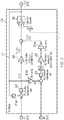
- Figure 2 shows a force and moment distributor system 20 according to an embodiment of the invention which receives the longitudinal force input demand, Fx*, and yaw moment input demand, Mz*, and determines the braking and/or driving forces to be applied to each of the MLG assemblies 11, 12 in order to achieve those demands.
- the output of the system 20 is a vector (of size 1xN, where N represents the number of MLG assemblies, in this case two) of longitudinal force commands, F*_MLG, which comprises a longitudinal braking or driving force to be applied to each MLG assembly, respectively.
- the system 20 includes a longitudinal force overflow redistribution logic module 22 having an error-based PI controller which receives the longitudinal force input demand, Fx*, and, via a closed feedback loop 21, a scalar value representative of the vector of landing gear force commands, F*_MLG.
- the closed feedback loop 21 includes a summation module 21a which adds together the values within the vector of landing gear force commands, F*_MLG, to determine the representative scalar value.
- the longitudinal force overflow redistribution logic module 22 determines an error between the longitudinal force input demand, Fx*, and the representative scalar value of the vector of landing gear force commands, F*_MLG, and uses that error to calculate a corrected longitudinal force input demand, Fx_R.
- the corrected longitudinal force input demand, Fx_R is received by a longitudinal force distributor module 24, which multiplies the corrected longitudinal force input demand, Fx_R, by a plurality of force distribution parameters, one force distribution parameter for each MLG assembly.
- Each force distribution parameter determines the proportion of braking or driving force to be achieved by its respective MLG assembly in order to achieve the corrected longitudinal force input demand, Fx_R.
- the output of the longitudinal force distributor module 24 is thus a vector of distributed longitudinal force commands, Fx_Long, each component of the vector representing a longitudinal braking or driving force command to be achieved by each MLG assembly 11, 12 in order to achieve the corrected longitudinal force input demand, Fx_R.
- the force distribution parameters are selected so that the longitudinal force command for each of the MLG assemblies (i.e. the braking or driving force to be achieved by those MLG assemblies) is the same.
- the longitudinal force distributor module 24 achieves symmetric distribution, so that the application of a longitudinal force command cannot result in a resultant yaw moment being applied to the aircraft.
- the yaw moment input demand, Mz* is received by a moment overflow redistribution logic module 23, which is similar to the longitudinal force overflow redistribution logic module 22.
- the closed feedback loop 21 includes a moment conversion module 21b which converts the vector of landing gear force commands, F*_MLG, into a scalar value, Mz, representative of the yaw moment represented by that vector, and delivers that representative scalar value, Mz, to the moment overflow redistribution logic module 23.
- An error-based PI controller of the moment overflow redistribution logic module 23 determines an error between the received yaw moment input demand, Mz*, and the scalar value, Mz, and uses that error to calculate a corrected yaw moment input demand, Mz_R.
- the corrected yaw moment input demand, Mz_R is received by a moment distributor module 25, which multiplies the corrected yaw moment input demand, Mz_R, by a plurality of moment distribution parameters, one moment distribution parameter for each MLG assembly 11, 12.
- Each moment distribution parameter determines the proportion of longitudinal braking or driving force to be achieved by its respective MLG assembly in order to achieve the corrected moment input demand, Mz_R.
- the output of the moment distributor module 25 is thus a vector of distributed moment commands.
- the vector is output to a force conversion module 25a, which converts each of the distributed moment commands into an equivalent longitudinal force command.
- the force conversion module 25a thus outputs a vector, Fx_Lat, in which each component represents a longitudinal braking or driving force command to be achieved by each MLG assembly 11, 12 in order to achieve the corrected yaw moment input demand, Mz_R.
- the moment distribution parameters are selected so that the longitudinal force command for each of the MLG assemblies (i.e. the braking or driving force to be achieved by those MLG assemblies) has an equal magnitude but opposite direction.
- the moment distributor module 25 achieves an anti-symmetric distribution, so that there is no coupling between the longitudinal force commands and yaw moment commands. That is, the application of a yaw moment command cannot result in a resultant longitudinal force being applied to the aircraft.
- the vectors Fx_Long and Fx_Lat from the longitudinal force distributor module 24 and moment distributor module 25, respectively, are received by a dynamic saturator 26, which applies a plurality of saturation limits to the longitudinal force commands.
- the saturation limits are runtime defined in accordance with data received from a reconfiguration module (not shown) which provides information concerning, for each MLG assembly 11, 12: the type(s) of actuator available; the operational status of that actuator; the health, i.e. fitness, of the actuator; runway conditions; operational scenarios; or any other structural, operational or system constraints.
- the monitoring system may provide information indicating that an actuator of one of the MLG assemblies 11, 12 is operating sub-optimally or has experienced a failure mode, and the saturation limits may accordingly be runtime adjusted to ensure that that actuator is not overloaded.
- the output of the dynamic saturator is the vector of landing gear longitudinal force commands, F*_MLG, which is generated from a combination of the vectors Fx_Long and Fx_Lat.
- the longitudinal force overflow redistribution logic module 22 and moment overflow redistribution logic module 23 each include runtime defined control gains which are used to calculate the corrected longitudinal force input demand, Fx_R, and corrected yaw moment input demand, Mz_R, respectively.
- the control gains are runtime defined in accordance with data received from the reconfiguration module, in the same way as for the saturation limits of the dynamic saturator 26 as discussed above. The control gains can thus be used to prioritise either the longitudinal force demand, Fx*, or the yaw moment demand, Mz*, depending on the particular operational situation at any one time.
- control gains can be configured so as to reduce the braking force applied to one of the MLG assemblies below 100%, i.e. to prioritise the yaw moment demand at the expense of the longitudinal force demand.
- the longitudinal force overflow redistribution logic module 22 and moment overflow redistribution logic module 23 thus internally redistribute the 'overflows' (i.e. the proportion of longitudinal braking or driving force that cannot be achieved by the MLG assemblies) in order to determine a combination of longitudinal force commands for the MLG assemblies that satisfies a predetermined priority (e.g. always achieve the yaw moment demand, even if this results in non-achievement of the longitudinal force demand, or vice versa). This can be referred to as optimally distributing the overflows.
- a predetermined priority e.g. always achieve the yaw moment demand, even if this results in non-achievement of the longitudinal force demand, or vice versa.
- the force and moment distribution parameters can also be runtime adjusted in accordance with data received from the reconfiguration module.
- runtime information concerning: the type(s) of actuator available; the operational status of that actuator; the health, i.e. fitness, of the actuator; runway conditions; operational scenarios; or any other structural, operational or system constraints, can be used to determine in what proportion the longitudinal force input demand, Fx*, and moment input demand, Mz*, should be distributed between the MLG assemblies.
Landscapes
- Engineering & Computer Science (AREA)
- Aviation & Aerospace Engineering (AREA)
- Mechanical Engineering (AREA)
- Transportation (AREA)
- Radar, Positioning & Navigation (AREA)
- Remote Sensing (AREA)
- Physics & Mathematics (AREA)
- General Physics & Mathematics (AREA)
- Automation & Control Theory (AREA)
- Regulating Braking Force (AREA)
- Electric Propulsion And Braking For Vehicles (AREA)
Claims (15)
- Système de distributeur de forces et de moments de train d'atterrissage (20) pour un aéronef ayant un axe longitudinal aligné dans une direction avant-arrière, un axe vertical perpendiculaire à l'axe longitudinal, et un train d'atterrissage comprenant une paire de trains d'atterrissage principaux (11, 12) disposés de façon symétrique autour de l'axe longitudinal (3), chaque train d'atterrissage principal comportant un actionneur agencé de façon à freiner et/ou à entraîner une ou plusieurs roues, le système de distribution de forces comprenant :un module de distribution agencé de façon à : recevoir une demande d'entrée comprenant une demande d'entrée de force longitudinale correspondant à une force de freinage ou d'entraînement désirée le long de l'axe longitudinal pour le train d'atterrissage et une demande d'entrée de moment correspondant à un moment désiré autour de l'axe vertical pour le train d'atterrissage ; et à utiliser la demande d'entrée reçue pour calculer un ordre de sortie comprenant, pour chaque train d'atterrissage principal, un ordre de sortie de force longitudinale correspondant à une force de freinage ou d'entraînement le long de l'axe longitudinal devant être appliquée audit train d'atterrissage principal de façon à obtenir la demande d'entrée de force longitudinale, et un ordre de sortie de moment correspondant à une force de freinage ou d'entraînement le long de l'axe longitudinal devant être appliquée audit train d'atterrissage principal de façon à obtenir la demande d'entrée de moment ; etun module de boucle de rétroaction basé sur l'erreur agencé de façon à : calculer une différence d'erreur entre l'ordre de sortie et la demande d'entrée ; utiliser la différence d'erreur calculée de façon à calculer une demande de force longitudinale corrigée et une demande de moment corrigée ; et délivrer en sortie la demande d'entrée de force longitudinale corrigée et la demande d'entrée de moment corrigée au module de distribution de telle sorte qu'elles soient reçues à titre de demande d'entrée de force longitudinale et de demande d'entrée de moment, respectivement, de la demande d'entrée.
- Système (20) selon la revendication 1, dans lequel le module de boucle de rétroaction basé sur l'erreur comprend une première boucle de rétroaction fermée agencée de façon à calculer une première différence d'erreur entre une somme de la pluralité d'ordres de sortie de force longitudinale et la demande d'entrée de force longitudinale ; et une deuxième boucle de rétroaction fermée agencée de façon à calculer une deuxième différence d'erreur entre une somme de la pluralité d'ordres de sortie de moment et la demande d'entrée de moment, et le module de boucle de rétroaction basé sur l'erreur est agencé de façon à utiliser la première différence d'erreur de façon à calculer la demande d'entrée de force corrigée et à utiliser la deuxième différence d'erreur de façon à calculer la demande d'entrée de moment corrigée.
- Système (20) selon la revendication 1 ou la revendication 2, dans lequel le module de distribution est agencé de façon à calculer l'ordre de sortie de telle sorte que l'ordre de sortie de force longitudinale pour chacun de la paire de trains d'atterrissage principaux (11, 12) soit le même.
- Système (20) selon l'une quelconque des revendications 1 à 3, dans lequel le module de distribution est agencé de façon à calculer l'ordre de sortie de telle sorte que l'ordre de sortie de moment pour l'un de la paire de trains d'atterrissage principaux soit d'amplitude égale mais de direction opposée à celle de l'autre de la paire de trains d'atterrissage principaux (11, 12).
- Système (20) selon l'une quelconque des revendications 1 à 4, dans lequel le module de distribution est agencé de façon à calculer l'ordre de sortie par la multiplication de l'ordre d'entrée reçu par une pluralité de paramètres de distribution, chaque paramètre de distribution correspondant à une caractéristique de l'actionneur de l'un de la paire de trains d'atterrissage principaux (11, 12).
- Système (20) selon la revendication 5, dans lequel les paramètres de distribution peuvent être un temps d'exécution ajusté en fonction d'un ou de plusieurs parmi : des scénarios fonctionnels, une configuration de système, des contraintes structurelles, un type d'actionneur, un ajustement d'actionneur et une disponibilité d'actionneur.
- Système (20) selon la revendication 2, dans lequel le module de boucle de rétroaction basé sur l'erreur est agencé de façon à appliquer un premier gain de commande à la première différence d'erreur de façon à calculer la demande d'entrée de force corrigée, et à appliquer un deuxième gain de commande à la deuxième différence d'erreur de façon à calculer la demande d'entrée de moment corrigée.
- Système (20) selon la revendication 7, dans lequel les premier et deuxième gains de commande peuvent être un temps d'exécution ajusté en fonction d'un ou de plusieurs parmi : des scénarios fonctionnels, une configuration de système, des contraintes structurelles, un type d'actionneur, un ajustement d'actionneur et une disponibilité d'actionneur.
- Système (20) selon la revendication 7 ou la revendication 8, dans lequel les premier et deuxième gains de commande peuvent être un temps d'exécution ajusté de façon à donner la priorité soit à la demande d'entrée de force longitudinale soit à la demande d'entrée de moment.
- Système (20) selon l'une quelconque des revendications 1 à 9, comprenant un module de saturation de priorité agencé de façon à : recevoir la demande d'entrée de force longitudinale et la demande d'entrée de moment ; limiter soit la demande d'entrée de force longitudinale soit la demande d'entrée de moment en fonction d'une ou de plusieurs valeurs de saturation de priorité ajustées selon un temps d'exécution ; et délivrer en sortie la demande d'entrée de force longitudinale et la demande d'entrée de moment au module de distribution.
- Système (20) selon la revendication 10, dans lequel les valeurs de saturation de priorité sont ajustées en fonction d'un ou de plusieurs parmi : des scénarios fonctionnels, une configuration de système, des contraintes structurelles, un type d'actionneur, un ajustement d'actionneur et une disponibilité d'actionneur.
- Système (20) selon l'une quelconque des revendications 1 à 11, comprenant un module de saturation dynamique agencé de façon à : recevoir l'ordre de sortie à partir du module de distribution ; recevoir une pluralité de valeurs de saturation dynamique ajustées selon un temps d'exécution ; et limiter l'ordre de sortie en fonction des valeurs de saturation dynamique.
- Système (20) selon la revendication 12, dans lequel chacune des valeurs de saturation dynamique dépend d'un ou de plusieurs parmi : des scénarios fonctionnels, une configuration de système, des contraintes structurelles, un type d'actionneur, un ajustement d'actionneur et une disponibilité d'actionneur.
- Système (20) selon la revendication 10, comprenant un module de saturation dynamique agencé de façon à : recevoir l'ordre de sortie à partir du module de distribution ; recevoir une pluralité de valeurs de saturation dynamique ajustées selon un temps d'exécution ; et limiter l'ordre de sortie en fonction des valeurs de saturation dynamique, et dans lequel le module de saturation de priorité est agencé de façon à redistribuer de façon optimale une partie de chacune de la demande d'entrée de force longitudinale et de la demande d'entrée de moment reçues qui dépasse les valeurs de saturation dynamique.
- Système (20) selon l'une quelconque des revendications 1 à 12, comprenant un module de reconfiguration agencé de façon à recevoir des paramètres de reconfiguration indicatifs d'un ou de plusieurs parmi : un scénario fonctionnel, une configuration de système, des contraintes structurelles, un type d'actionneur, un ajustement d'actionneur, et une disponibilité d'actionneur, et à délivrer en sortie des valeurs de saturation de priorité, des valeurs de saturation dynamique, des premier et deuxième gains de commande et/ou paramètres de distribution basés sur ces paramètres de reconfiguration dans le cas d'un changement dans lesdits paramètres au nombre d'un ou de plusieurs, sans interruption de son fonctionnement continu.
Applications Claiming Priority (2)
| Application Number | Priority Date | Filing Date | Title |
|---|---|---|---|
| GBGB1220618.1A GB201220618D0 (en) | 2012-11-16 | 2012-11-16 | Landing gear force and moment distributer |
| PCT/GB2013/053013 WO2014076486A1 (fr) | 2012-11-16 | 2013-11-15 | Distributeur de force et de moment de train d'atterrissage |
Publications (2)
| Publication Number | Publication Date |
|---|---|
| EP2920070A1 EP2920070A1 (fr) | 2015-09-23 |
| EP2920070B1 true EP2920070B1 (fr) | 2018-03-14 |
Family
ID=47521261
Family Applications (1)
| Application Number | Title | Priority Date | Filing Date |
|---|---|---|---|
| EP13792963.4A Active EP2920070B1 (fr) | 2012-11-16 | 2013-11-15 | Dstributeur de forces et de couple de braquage pour système de propulsion ou de freinage d'un atterrisseur d'aéronef |
Country Status (5)
| Country | Link |
|---|---|
| US (1) | US9348335B2 (fr) |
| EP (1) | EP2920070B1 (fr) |
| CN (1) | CN104936860B (fr) |
| GB (1) | GB201220618D0 (fr) |
| WO (1) | WO2014076486A1 (fr) |
Cited By (1)
| Publication number | Priority date | Publication date | Assignee | Title |
|---|---|---|---|---|
| EP4242076A1 (fr) | 2022-03-07 | 2023-09-13 | Airbus Defence and Space GmbH | Procédé de commande de freinage et dispositif de commande de freinage pour un véhicule, tel qu'un aéronef |
Families Citing this family (16)
| Publication number | Priority date | Publication date | Assignee | Title |
|---|---|---|---|---|
| GB201220616D0 (en) * | 2012-11-16 | 2013-01-02 | Airbus Operations Ltd | Aircraft landing gear longitudinal force control |
| USD750008S1 (en) * | 2014-07-16 | 2016-02-23 | Icon Aircraft, Inc. | Aircraft nose landing gear fork |
| GB2533179B (en) * | 2014-12-10 | 2020-08-26 | Airbus Operations Ltd | Control method and apparatus for an aircraft when taxiing |
| GB2534915A (en) | 2015-02-05 | 2016-08-10 | Airbus Operations Ltd | Method and apparatus for control of a steerable landing gear |
| GB2537860A (en) | 2015-04-28 | 2016-11-02 | Airbus Operations Sas | Aircraft steering system |
| GB2540183A (en) * | 2015-07-08 | 2017-01-11 | Airbus Operations Ltd | Braking control system for an aircraft |
| US9862365B2 (en) * | 2016-01-22 | 2018-01-09 | Goodrich Corporation | Systems and methods for reducing disturbances caused by using gain scheduling in electronic brake actuator controls |
| PL3232284T3 (pl) | 2016-04-11 | 2020-06-29 | Airbus Operations Limited | Sposób i urządzenie do sterowania kierowalnym podwoziem |
| US10086925B2 (en) * | 2016-07-13 | 2018-10-02 | Embraer S.A. | Use of automatic pitch control to improve braking performance |
| US10300897B2 (en) * | 2017-05-15 | 2019-05-28 | Goodrich Corporation | Brake load balance and runway centering techniques |
| FR3072943B1 (fr) * | 2017-10-27 | 2021-12-10 | Safran Landing Systems | Atterrisseur d'aeronef a roues freinees et roues motorisees |
| GB2572161B (en) * | 2018-03-20 | 2020-09-09 | Airbus Operations Ltd | An aircraft landing gear |
| FR3079494A1 (fr) * | 2018-03-29 | 2019-10-04 | Safran Landing Systems | Atterrisseur d'aeronef a bogie portant des roues freinees et au moins une roue motorisee |
| GB2588377A (en) | 2019-10-09 | 2021-04-28 | Airbus Operations Ltd | Heading control system |
| GB2621823A (en) * | 2022-08-17 | 2024-02-28 | Airbus Operations Ltd | Method and apparatus for controlling aircraft ground manoeuvres |
| CN119902549B (zh) * | 2023-10-23 | 2025-11-28 | 广东汇天航空航天科技有限公司 | 飞行器控制方法、装置以及飞行器 |
Family Cites Families (12)
| Publication number | Priority date | Publication date | Assignee | Title |
|---|---|---|---|---|
| US4078845A (en) * | 1976-08-13 | 1978-03-14 | The Boeing Company | Limited-slip brake control system |
| US4180223A (en) * | 1977-12-28 | 1979-12-25 | The Boeing Company | Limited-slip brake control system |
| US4482961A (en) * | 1981-09-18 | 1984-11-13 | The Boeing Company | Automatic control system for directional control of an aircraft during landing rollout |
| US6684147B2 (en) * | 2001-12-17 | 2004-01-27 | Hydro-Aire, Inc. | Sliding integral proportional (SIP) controller for aircraft skid control |
| US6758440B1 (en) * | 2003-03-21 | 2004-07-06 | Curtiss-Wright Electro-Mechanical Corporation | Electromagnetic aircraft arrestor system |
| US7237748B2 (en) * | 2003-12-15 | 2007-07-03 | Delos Aerospace, Llc | Landing gear method and apparatus for braking and maneuvering |
| GB0405614D0 (en) * | 2004-03-12 | 2004-04-21 | Airbus Uk Ltd | Advanced braking system |
| US7975960B2 (en) * | 2005-08-29 | 2011-07-12 | Borealis Technical Limited | Nosewheel control apparatus |
| US8016366B2 (en) | 2006-06-02 | 2011-09-13 | Goodrich Corporation | Differential brake control and weighted average wheel speed for brake control system |
| DE102008011791B4 (de) * | 2008-02-29 | 2013-09-19 | Airbus Operations Gmbh | Integriertes multifunktionales Radantriebssystem für Luftfahrzeuge |
| FR2963968B1 (fr) * | 2010-08-18 | 2013-07-05 | Messier Bugatti | Procede de gestion d'un mouvement de lacet d'un aeronef roulant au sol. |
| FR2965074B1 (fr) * | 2010-09-21 | 2012-08-31 | Messier Bugatti | Procede de gestion d'un mouvement au sol d'un aeronef. |
-
2012
- 2012-11-16 GB GBGB1220618.1A patent/GB201220618D0/en not_active Ceased
-
2013
- 2013-11-15 US US14/443,252 patent/US9348335B2/en active Active
- 2013-11-15 EP EP13792963.4A patent/EP2920070B1/fr active Active
- 2013-11-15 WO PCT/GB2013/053013 patent/WO2014076486A1/fr not_active Ceased
- 2013-11-15 CN CN201380070565.0A patent/CN104936860B/zh not_active Expired - Fee Related
Cited By (2)
| Publication number | Priority date | Publication date | Assignee | Title |
|---|---|---|---|---|
| EP4242076A1 (fr) | 2022-03-07 | 2023-09-13 | Airbus Defence and Space GmbH | Procédé de commande de freinage et dispositif de commande de freinage pour un véhicule, tel qu'un aéronef |
| WO2023169795A1 (fr) | 2022-03-07 | 2023-09-14 | Airbus Defence and Space GmbH | Procédé de commande de frein et dispositif de commande de frein pour un véhicule, tel qu'un aéronef |
Also Published As
| Publication number | Publication date |
|---|---|
| CN104936860B (zh) | 2017-03-08 |
| WO2014076486A1 (fr) | 2014-05-22 |
| GB201220618D0 (en) | 2013-01-02 |
| US9348335B2 (en) | 2016-05-24 |
| EP2920070A1 (fr) | 2015-09-23 |
| US20150301531A1 (en) | 2015-10-22 |
| CN104936860A (zh) | 2015-09-23 |
Similar Documents
| Publication | Publication Date | Title |
|---|---|---|
| EP2920070B1 (fr) | Dstributeur de forces et de couple de braquage pour système de propulsion ou de freinage d'un atterrisseur d'aéronef | |
| EP4001104B1 (fr) | Commande de force longitudinale de train d'atterrissage d'aéronef | |
| CN111483589B (zh) | 用于飞行器的制动控制系统 | |
| CN106335633B (zh) | 用于飞行器起落架性能监测的数据处理单元 | |
| CN111483588B (zh) | 飞行器起落架轮的差动制动 | |
| CN106335634B (zh) | 飞行器及其转向系统、转向方法和转向系统控制器 | |
| US10065729B2 (en) | Control method and apparatus for an aircraft when taxiing | |
| EP4242076B1 (fr) | Procédé de commande de freinage et dispositif de commande de freinage pour un véhicule, tel qu'un aéronef |
Legal Events
| Date | Code | Title | Description |
|---|---|---|---|
| PUAI | Public reference made under article 153(3) epc to a published international application that has entered the european phase |
Free format text: ORIGINAL CODE: 0009012 |
|
| 17P | Request for examination filed |
Effective date: 20150527 |
|
| AK | Designated contracting states |
Kind code of ref document: A1 Designated state(s): AL AT BE BG CH CY CZ DE DK EE ES FI FR GB GR HR HU IE IS IT LI LT LU LV MC MK MT NL NO PL PT RO RS SE SI SK SM TR |
|
| AX | Request for extension of the european patent |
Extension state: BA ME |
|
| DAX | Request for extension of the european patent (deleted) | ||
| GRAP | Despatch of communication of intention to grant a patent |
Free format text: ORIGINAL CODE: EPIDOSNIGR1 |
|
| INTG | Intention to grant announced |
Effective date: 20171013 |
|
| GRAS | Grant fee paid |
Free format text: ORIGINAL CODE: EPIDOSNIGR3 |
|
| GRAA | (expected) grant |
Free format text: ORIGINAL CODE: 0009210 |
|
| AK | Designated contracting states |
Kind code of ref document: B1 Designated state(s): AL AT BE BG CH CY CZ DE DK EE ES FI FR GB GR HR HU IE IS IT LI LT LU LV MC MK MT NL NO PL PT RO RS SE SI SK SM TR |
|
| REG | Reference to a national code |
Ref country code: GB Ref legal event code: FG4D |
|
| REG | Reference to a national code |
Ref country code: CH Ref legal event code: EP Ref country code: AT Ref legal event code: REF Ref document number: 978626 Country of ref document: AT Kind code of ref document: T Effective date: 20180315 |
|
| REG | Reference to a national code |
Ref country code: IE Ref legal event code: FG4D |
|
| REG | Reference to a national code |
Ref country code: DE Ref legal event code: R096 Ref document number: 602013034453 Country of ref document: DE |
|
| REG | Reference to a national code |
Ref country code: NL Ref legal event code: MP Effective date: 20180314 |
|
| REG | Reference to a national code |
Ref country code: LT Ref legal event code: MG4D |
|
| PG25 | Lapsed in a contracting state [announced via postgrant information from national office to epo] |
Ref country code: CY Free format text: LAPSE BECAUSE OF FAILURE TO SUBMIT A TRANSLATION OF THE DESCRIPTION OR TO PAY THE FEE WITHIN THE PRESCRIBED TIME-LIMIT Effective date: 20180314 Ref country code: LT Free format text: LAPSE BECAUSE OF FAILURE TO SUBMIT A TRANSLATION OF THE DESCRIPTION OR TO PAY THE FEE WITHIN THE PRESCRIBED TIME-LIMIT Effective date: 20180314 Ref country code: FI Free format text: LAPSE BECAUSE OF FAILURE TO SUBMIT A TRANSLATION OF THE DESCRIPTION OR TO PAY THE FEE WITHIN THE PRESCRIBED TIME-LIMIT Effective date: 20180314 Ref country code: NO Free format text: LAPSE BECAUSE OF FAILURE TO SUBMIT A TRANSLATION OF THE DESCRIPTION OR TO PAY THE FEE WITHIN THE PRESCRIBED TIME-LIMIT Effective date: 20180614 Ref country code: HR Free format text: LAPSE BECAUSE OF FAILURE TO SUBMIT A TRANSLATION OF THE DESCRIPTION OR TO PAY THE FEE WITHIN THE PRESCRIBED TIME-LIMIT Effective date: 20180314 |
|
| REG | Reference to a national code |
Ref country code: AT Ref legal event code: MK05 Ref document number: 978626 Country of ref document: AT Kind code of ref document: T Effective date: 20180314 |
|
| PG25 | Lapsed in a contracting state [announced via postgrant information from national office to epo] |
Ref country code: RS Free format text: LAPSE BECAUSE OF FAILURE TO SUBMIT A TRANSLATION OF THE DESCRIPTION OR TO PAY THE FEE WITHIN THE PRESCRIBED TIME-LIMIT Effective date: 20180314 Ref country code: SE Free format text: LAPSE BECAUSE OF FAILURE TO SUBMIT A TRANSLATION OF THE DESCRIPTION OR TO PAY THE FEE WITHIN THE PRESCRIBED TIME-LIMIT Effective date: 20180314 Ref country code: LV Free format text: LAPSE BECAUSE OF FAILURE TO SUBMIT A TRANSLATION OF THE DESCRIPTION OR TO PAY THE FEE WITHIN THE PRESCRIBED TIME-LIMIT Effective date: 20180314 Ref country code: BG Free format text: LAPSE BECAUSE OF FAILURE TO SUBMIT A TRANSLATION OF THE DESCRIPTION OR TO PAY THE FEE WITHIN THE PRESCRIBED TIME-LIMIT Effective date: 20180614 Ref country code: GR Free format text: LAPSE BECAUSE OF FAILURE TO SUBMIT A TRANSLATION OF THE DESCRIPTION OR TO PAY THE FEE WITHIN THE PRESCRIBED TIME-LIMIT Effective date: 20180615 |
|
| PG25 | Lapsed in a contracting state [announced via postgrant information from national office to epo] |
Ref country code: AL Free format text: LAPSE BECAUSE OF FAILURE TO SUBMIT A TRANSLATION OF THE DESCRIPTION OR TO PAY THE FEE WITHIN THE PRESCRIBED TIME-LIMIT Effective date: 20180314 Ref country code: NL Free format text: LAPSE BECAUSE OF FAILURE TO SUBMIT A TRANSLATION OF THE DESCRIPTION OR TO PAY THE FEE WITHIN THE PRESCRIBED TIME-LIMIT Effective date: 20180314 Ref country code: PL Free format text: LAPSE BECAUSE OF FAILURE TO SUBMIT A TRANSLATION OF THE DESCRIPTION OR TO PAY THE FEE WITHIN THE PRESCRIBED TIME-LIMIT Effective date: 20180314 Ref country code: RO Free format text: LAPSE BECAUSE OF FAILURE TO SUBMIT A TRANSLATION OF THE DESCRIPTION OR TO PAY THE FEE WITHIN THE PRESCRIBED TIME-LIMIT Effective date: 20180314 Ref country code: ES Free format text: LAPSE BECAUSE OF FAILURE TO SUBMIT A TRANSLATION OF THE DESCRIPTION OR TO PAY THE FEE WITHIN THE PRESCRIBED TIME-LIMIT Effective date: 20180314 Ref country code: EE Free format text: LAPSE BECAUSE OF FAILURE TO SUBMIT A TRANSLATION OF THE DESCRIPTION OR TO PAY THE FEE WITHIN THE PRESCRIBED TIME-LIMIT Effective date: 20180314 Ref country code: IT Free format text: LAPSE BECAUSE OF FAILURE TO SUBMIT A TRANSLATION OF THE DESCRIPTION OR TO PAY THE FEE WITHIN THE PRESCRIBED TIME-LIMIT Effective date: 20180314 |
|
| PG25 | Lapsed in a contracting state [announced via postgrant information from national office to epo] |
Ref country code: SK Free format text: LAPSE BECAUSE OF FAILURE TO SUBMIT A TRANSLATION OF THE DESCRIPTION OR TO PAY THE FEE WITHIN THE PRESCRIBED TIME-LIMIT Effective date: 20180314 Ref country code: SM Free format text: LAPSE BECAUSE OF FAILURE TO SUBMIT A TRANSLATION OF THE DESCRIPTION OR TO PAY THE FEE WITHIN THE PRESCRIBED TIME-LIMIT Effective date: 20180314 Ref country code: AT Free format text: LAPSE BECAUSE OF FAILURE TO SUBMIT A TRANSLATION OF THE DESCRIPTION OR TO PAY THE FEE WITHIN THE PRESCRIBED TIME-LIMIT Effective date: 20180314 Ref country code: CZ Free format text: LAPSE BECAUSE OF FAILURE TO SUBMIT A TRANSLATION OF THE DESCRIPTION OR TO PAY THE FEE WITHIN THE PRESCRIBED TIME-LIMIT Effective date: 20180314 |
|
| REG | Reference to a national code |
Ref country code: DE Ref legal event code: R097 Ref document number: 602013034453 Country of ref document: DE |
|
| PG25 | Lapsed in a contracting state [announced via postgrant information from national office to epo] |
Ref country code: PT Free format text: LAPSE BECAUSE OF FAILURE TO SUBMIT A TRANSLATION OF THE DESCRIPTION OR TO PAY THE FEE WITHIN THE PRESCRIBED TIME-LIMIT Effective date: 20180716 |
|
| PLBE | No opposition filed within time limit |
Free format text: ORIGINAL CODE: 0009261 |
|
| STAA | Information on the status of an ep patent application or granted ep patent |
Free format text: STATUS: NO OPPOSITION FILED WITHIN TIME LIMIT |
|
| PG25 | Lapsed in a contracting state [announced via postgrant information from national office to epo] |
Ref country code: DK Free format text: LAPSE BECAUSE OF FAILURE TO SUBMIT A TRANSLATION OF THE DESCRIPTION OR TO PAY THE FEE WITHIN THE PRESCRIBED TIME-LIMIT Effective date: 20180314 |
|
| 26N | No opposition filed |
Effective date: 20181217 |
|
| PG25 | Lapsed in a contracting state [announced via postgrant information from national office to epo] |
Ref country code: SI Free format text: LAPSE BECAUSE OF FAILURE TO SUBMIT A TRANSLATION OF THE DESCRIPTION OR TO PAY THE FEE WITHIN THE PRESCRIBED TIME-LIMIT Effective date: 20180314 |
|
| REG | Reference to a national code |
Ref country code: CH Ref legal event code: PL |
|
| PG25 | Lapsed in a contracting state [announced via postgrant information from national office to epo] |
Ref country code: LU Free format text: LAPSE BECAUSE OF NON-PAYMENT OF DUE FEES Effective date: 20181115 Ref country code: MC Free format text: LAPSE BECAUSE OF FAILURE TO SUBMIT A TRANSLATION OF THE DESCRIPTION OR TO PAY THE FEE WITHIN THE PRESCRIBED TIME-LIMIT Effective date: 20180314 |
|
| REG | Reference to a national code |
Ref country code: BE Ref legal event code: MM Effective date: 20181130 |
|
| REG | Reference to a national code |
Ref country code: IE Ref legal event code: MM4A |
|
| PG25 | Lapsed in a contracting state [announced via postgrant information from national office to epo] |
Ref country code: CH Free format text: LAPSE BECAUSE OF NON-PAYMENT OF DUE FEES Effective date: 20181130 Ref country code: LI Free format text: LAPSE BECAUSE OF NON-PAYMENT OF DUE FEES Effective date: 20181130 |
|
| PG25 | Lapsed in a contracting state [announced via postgrant information from national office to epo] |
Ref country code: IE Free format text: LAPSE BECAUSE OF NON-PAYMENT OF DUE FEES Effective date: 20181115 |
|
| PG25 | Lapsed in a contracting state [announced via postgrant information from national office to epo] |
Ref country code: BE Free format text: LAPSE BECAUSE OF NON-PAYMENT OF DUE FEES Effective date: 20181130 |
|
| PG25 | Lapsed in a contracting state [announced via postgrant information from national office to epo] |
Ref country code: MT Free format text: LAPSE BECAUSE OF NON-PAYMENT OF DUE FEES Effective date: 20181115 |
|
| PG25 | Lapsed in a contracting state [announced via postgrant information from national office to epo] |
Ref country code: TR Free format text: LAPSE BECAUSE OF FAILURE TO SUBMIT A TRANSLATION OF THE DESCRIPTION OR TO PAY THE FEE WITHIN THE PRESCRIBED TIME-LIMIT Effective date: 20180314 |
|
| PG25 | Lapsed in a contracting state [announced via postgrant information from national office to epo] |
Ref country code: MK Free format text: LAPSE BECAUSE OF NON-PAYMENT OF DUE FEES Effective date: 20180314 Ref country code: HU Free format text: LAPSE BECAUSE OF FAILURE TO SUBMIT A TRANSLATION OF THE DESCRIPTION OR TO PAY THE FEE WITHIN THE PRESCRIBED TIME-LIMIT; INVALID AB INITIO Effective date: 20131115 |
|
| PG25 | Lapsed in a contracting state [announced via postgrant information from national office to epo] |
Ref country code: IS Free format text: LAPSE BECAUSE OF FAILURE TO SUBMIT A TRANSLATION OF THE DESCRIPTION OR TO PAY THE FEE WITHIN THE PRESCRIBED TIME-LIMIT Effective date: 20180714 |
|
| PGFP | Annual fee paid to national office [announced via postgrant information from national office to epo] |
Ref country code: DE Payment date: 20251119 Year of fee payment: 13 |
|
| PGFP | Annual fee paid to national office [announced via postgrant information from national office to epo] |
Ref country code: GB Payment date: 20251121 Year of fee payment: 13 |
|
| PGFP | Annual fee paid to national office [announced via postgrant information from national office to epo] |
Ref country code: FR Payment date: 20251125 Year of fee payment: 13 |