EP4242076A1 - Procédé de commande de freinage et dispositif de commande de freinage pour un véhicule, tel qu'un aéronef - Google Patents
Procédé de commande de freinage et dispositif de commande de freinage pour un véhicule, tel qu'un aéronef Download PDFInfo
- Publication number
- EP4242076A1 EP4242076A1 EP22382210.7A EP22382210A EP4242076A1 EP 4242076 A1 EP4242076 A1 EP 4242076A1 EP 22382210 A EP22382210 A EP 22382210A EP 4242076 A1 EP4242076 A1 EP 4242076A1
- Authority
- EP
- European Patent Office
- Prior art keywords
- brake
- demand
- signal
- brk
- dmd
- Prior art date
- Legal status (The legal status is an assumption and is not a legal conclusion. Google has not performed a legal analysis and makes no representation as to the accuracy of the status listed.)
- Granted
Links
Images



Classifications
-
- B—PERFORMING OPERATIONS; TRANSPORTING
- B60—VEHICLES IN GENERAL
- B60T—VEHICLE BRAKE CONTROL SYSTEMS OR PARTS THEREOF; BRAKE CONTROL SYSTEMS OR PARTS THEREOF, IN GENERAL; ARRANGEMENT OF BRAKING ELEMENTS ON VEHICLES IN GENERAL; PORTABLE DEVICES FOR PREVENTING UNWANTED MOVEMENT OF VEHICLES; VEHICLE MODIFICATIONS TO FACILITATE COOLING OF BRAKES
- B60T8/00—Arrangements for adjusting wheel-braking force to meet varying vehicular or ground-surface conditions, e.g. limiting or varying distribution of braking force
- B60T8/17—Using electrical or electronic regulation means to control braking
- B60T8/1701—Braking or traction control means specially adapted for particular types of vehicles
- B60T8/1703—Braking or traction control means specially adapted for particular types of vehicles for aircrafts
-
- B—PERFORMING OPERATIONS; TRANSPORTING
- B60—VEHICLES IN GENERAL
- B60T—VEHICLE BRAKE CONTROL SYSTEMS OR PARTS THEREOF; BRAKE CONTROL SYSTEMS OR PARTS THEREOF, IN GENERAL; ARRANGEMENT OF BRAKING ELEMENTS ON VEHICLES IN GENERAL; PORTABLE DEVICES FOR PREVENTING UNWANTED MOVEMENT OF VEHICLES; VEHICLE MODIFICATIONS TO FACILITATE COOLING OF BRAKES
- B60T13/00—Transmitting braking action from initiating means to ultimate brake actuator with power assistance or drive; Brake systems incorporating such transmitting means, e.g. air-pressure brake systems
- B60T13/10—Transmitting braking action from initiating means to ultimate brake actuator with power assistance or drive; Brake systems incorporating such transmitting means, e.g. air-pressure brake systems with fluid assistance, drive, or release
- B60T13/66—Electrical control in fluid-pressure brake systems
-
- B—PERFORMING OPERATIONS; TRANSPORTING
- B60—VEHICLES IN GENERAL
- B60T—VEHICLE BRAKE CONTROL SYSTEMS OR PARTS THEREOF; BRAKE CONTROL SYSTEMS OR PARTS THEREOF, IN GENERAL; ARRANGEMENT OF BRAKING ELEMENTS ON VEHICLES IN GENERAL; PORTABLE DEVICES FOR PREVENTING UNWANTED MOVEMENT OF VEHICLES; VEHICLE MODIFICATIONS TO FACILITATE COOLING OF BRAKES
- B60T13/00—Transmitting braking action from initiating means to ultimate brake actuator with power assistance or drive; Brake systems incorporating such transmitting means, e.g. air-pressure brake systems
- B60T13/10—Transmitting braking action from initiating means to ultimate brake actuator with power assistance or drive; Brake systems incorporating such transmitting means, e.g. air-pressure brake systems with fluid assistance, drive, or release
- B60T13/66—Electrical control in fluid-pressure brake systems
- B60T13/662—Electrical control in fluid-pressure brake systems characterised by specified functions of the control system components
-
- B—PERFORMING OPERATIONS; TRANSPORTING
- B60—VEHICLES IN GENERAL
- B60T—VEHICLE BRAKE CONTROL SYSTEMS OR PARTS THEREOF; BRAKE CONTROL SYSTEMS OR PARTS THEREOF, IN GENERAL; ARRANGEMENT OF BRAKING ELEMENTS ON VEHICLES IN GENERAL; PORTABLE DEVICES FOR PREVENTING UNWANTED MOVEMENT OF VEHICLES; VEHICLE MODIFICATIONS TO FACILITATE COOLING OF BRAKES
- B60T8/00—Arrangements for adjusting wheel-braking force to meet varying vehicular or ground-surface conditions, e.g. limiting or varying distribution of braking force
- B60T8/32—Arrangements for adjusting wheel-braking force to meet varying vehicular or ground-surface conditions, e.g. limiting or varying distribution of braking force responsive to a speed condition, e.g. acceleration or deceleration
- B60T8/321—Arrangements for adjusting wheel-braking force to meet varying vehicular or ground-surface conditions, e.g. limiting or varying distribution of braking force responsive to a speed condition, e.g. acceleration or deceleration deceleration
- B60T8/325—Systems specially adapted for aircraft
-
- B—PERFORMING OPERATIONS; TRANSPORTING
- B64—AIRCRAFT; AVIATION; COSMONAUTICS
- B64C—AEROPLANES; HELICOPTERS
- B64C25/00—Alighting gear
- B64C25/32—Alighting gear characterised by elements which contact the ground or similar surface
- B64C25/42—Arrangement or adaptation of brakes
-
- B—PERFORMING OPERATIONS; TRANSPORTING
- B64—AIRCRAFT; AVIATION; COSMONAUTICS
- B64C—AEROPLANES; HELICOPTERS
- B64C25/00—Alighting gear
- B64C25/32—Alighting gear characterised by elements which contact the ground or similar surface
- B64C25/42—Arrangement or adaptation of brakes
- B64C25/426—Braking devices providing an automatic sequence of braking
Definitions
- the invention relates to a brake control method.
- the invention further relates to a brake control device for a vehicle, such as an aircraft.
- Brake controls are known for example from EP 1 864 878 B1 , EP 2 920 070 B1 , EP 2 974 957 A1 , US 8 147 006 B2 , US 7 775 607 B2 , and US 5 707 118 A .
- a typical aircraft has a landing gear comprising a plurality of wheeled landing gear assemblies which support the aircraft when it is on the ground.
- a typical tricycle landing gear includes one or more nose landing gear (NLG) assemblies located forwards of the aircraft centre of gravity and a plurality of main landing gear (MLG) assemblies located rearwards of the aircraft centre of gravity.
- Another typical configuration is a tail wheel landing gear that includes one or more tail landing gear (TLG) assemblies located rearwards of the aircraft centre of gravity and a plurality of main landing gear (MLG) assemblies located forwards of the aircraft centre of gravity.
- the MLG assemblies are located in a symmetrical configuration with respect to the aircraft longitudinal axis and distributed laterally at a distance from it.
- Each MLG assembly includes one or more brakes that can be used for deceleration (also called longitudinal control) and lateral control of the aircraft during ground manoeuvres such as landing, taxiing and take off.
- the movement of such an aircraft on the ground is determined by control demands issued by the pilot or by a flight control system (FCS).
- FCS flight control system
- the brake system is required to generate a particular longitudinal force and a yaw moment on the aircraft.
- the demands from the pilot or the FCS may not be achievable, as the available brake force in each wheel is limited by the maximum brake torque and by the maximum friction force between the respective tyre and the ground.
- anti-skid systems include individual controllers for each braked wheel.
- the clamping force of each brake can be individually modulated by the respective anti-skid controller taking into account the slip conditions of the respective wheel.
- These systems are capable of achieving brake force values very close to the maximum achievable in all wheels. This maximizes the aircraft deceleration capability.
- each anti-skid controller is independent, the total sum of yaw moments is usually not actively controlled. As a consequence, the total sum of yaw moments generated by all braked wheels may not be the one demanded by the pilot or the Flight Control System.
- anti-skid systems implement grouped wheel control. These systems use a single anti-skid modulation signal to modulate the braking force of some or all brakes.
- the single anti-skid modulation signal is usually generated by a single anti-skid controller based on the slip conditions of the wheel with the greatest slip. These systems can control the yaw moment generated by the brake system and therefore prevent unwanted yaw moment.
- the invention provides a brake control method for controlling a braking system of a vehicle, preferably an aircraft, the braking system having a plurality of brake device groups, the method comprising:
- the braking system includes a brake command distributor unit that receives the priority demand signal and each of at least one first internal brake demand signal and each of at least one second internal brake demand signal, wherein the first internal brake demand signal is associated with the first brake target and the second internal brake demand signal is associated with the second brake target, and wherein the brake command distributor unit generates the brake command signals by combining the internal brake demand signals using a weight based on the priority demand signal.
- the brake command distributor unit determines each braking command signal by multiplying the first internal braking demand signal with a relative weight that is based on a difference of a predetermined value minus the priority demand signal and multiplying the second braking demand signal with the priority demand signal, wherein the brake command signal is the sum of the results of both multiplications.
- the braking system includes an individual brake control unit that receives the external brake demand signals and generates a plurality of individual brake demand signals each configured to maximize the first brake target, and feeds each individual brake demand signal to the brake command distributor unit as a first internal brake demand signal.
- the braking system includes a grouped brake control unit that receives the external brake demand signals and the first internal brake demand signals and generates a plurality of grouped brake demand signals each configured to maximize the second brake target, and feeds each group brake demand signal to the brake command distributor unit as a second internal brake demand signal.
- a grouped brake control unit that receives the external brake demand signals and the first internal brake demand signals and generates a plurality of grouped brake demand signals each configured to maximize the second brake target, and feeds each group brake demand signal to the brake command distributor unit as a second internal brake demand signal.
- the grouped brake control unit determines a limiting brake device signal that is indicative of a brake device limiting braking action, generates a first set of brake demands and a second set of brake demands, and outputs the first set of brake demands or the second set of brake demands depending on the limiting brake device signal.
- the limiting brake device is determined by the grouped brake control unit determining a first brake modifying signal that is the difference between a first external brake demand signal and the first individual brake demand signal, and a second brake modifying signal that is the difference between a second external brake demand signal and the second individual brake demand signal, wherein the limiting brake device signal is determined by the larger of the previously determined differences.
- a first brake demand signal has as the first brake target a longitudinal deceleration and a second brake demand signal has as the second brake target a yaw moment.
- the priority demand signal is a lateral/longitudinal priority signal.
- the brake command signals are generated such that the longitudinal deceleration or the yaw moment is prioritized based on the lateral/longitudinal priority signal.
- a first brake demand signal has as the first brake target a LH brake demand and a second brake demand signal has as the second brake target a RH brake demand, wherein the priority demand signal is a lateral/longitudinal priority signal.
- the LH brake command signal and the RH brake command signal are generated such that the longitudinal deceleration or the yaw moment is prioritized based on the lateral/longitudinal priority signal.
- the invention provides a brake control system for controlling a braking system of a vehicle, preferably an aircraft, the brake control system being configured for performing a previously described method.
- the invention provides a computer program containing instructions that, upon execution by a preferred brake control system, cause the brake control system to perform a previously described method.
- the invention provides a data storage containing or a data carrier signal transporting the preferred computer program.
- One idea is a brake control system capable of generating individual brake commands based on input brake demands and on an external input selecting the priority of the lateral control axis vs the longitudinal control axis.
- the brake control system includes an individual brake control function, a grouped brake control function and a brake command distributor.
- the individual brake control may increase, preferably maximize, the total brake force (which is an example for a first brake target) and may increase the deceleration performance.
- the grouped brake control function may try to achieve the demanded differential braking yaw moment (which is an example of a second brake target) and may increase the lateral control performance.
- the brake command distributor can generate the brake commands combining the outputs of the individual and the grouped brake control function taking into account the value of the external lateral/longitudinal priority factor.
- the brake control system can have two external brake demands (Brk_ext_dmd_1, Brk_ext_dmd_2), an external lateral/longitudinal priority demand (Lat_lon_prio_dmd) and generate an amount of n brake commands (Brk_cmd_1, ..., Brk_cmd_n) for an amount of n independently controllable brakes where n ⁇ 2.
- the external brake demands may include left hand (LH) / right hand (RH) brake demands, total brake force or yaw moment demands, or any other signal used for the purpose of demanding braking.
- the parameters used in the external brake demands (Brk_ext_dmd_1, Brk_ext_dmd_2), and the brake commands (Brk_cmd_1, ..., Brk_cmd_n) may be chosen from a group consisting of torques, forces, pressures, currents, voltages or any other parameter used for the purpose of demanding or commanding braking. These parameters may also be absolute values or percentages of a maximum or nominal value.
- the brake control system may generate the brake commands (Brk_cmd_1, ..., Brk_cmd_n) with the target of achieving both external brake demands (Brk_ext_dmd_1, Brk_ext_dmd_2).
- a priority to either longitudinal or lateral control is given depending on the value of the lateral/longitudinal priority factor (Lat_lon_prio_dmd).
- the brake control system increases, preferably maximizes, the achieved total brake force.
- the brake control system increases, preferably maximizes, the achieved differential braking yaw moment.
- the brake commands (Brk_cmd_1, ..., Brk_cmd_n) may be generated taking additional considerations into account (e.g. actuator status, generated loads, etc.).
- an Individual Brake Control function may generate n brake demands (Brk_indiv_dmd_1, ..., Brk_indiv_dmd_n) based on the external brake demands (Brk_ext_dmd_1 and Brk_ext_dmd_2) with the aim of increasing, preferably maximising, the deceleration performance (as an example of a first brake target).
- a grouped brake control function may generate n brake demands (Brk_group_dmd_1, ..., Brk_group_dmd_n) based on the external brake demands (Brk_ext_dmd_1, Brk_ext_dmd_2) and the n individual brake control function brake demands (Brk_indiv_dmd_1, ..., Brk_indiv_dmd_n) with the aim of increasing, preferably maximising, the lateral control performance (as an example of a second brake target).
- the brake command distributor function may generate each brake command (Brk_cmd_i) by a weighted combination of the respective individual brake control demand (Brk_indiv_dmd_i) and the respective grouped brake control demand (Brk_group_dmd_i) taking into account the value of the priority factor (Lat_lon_prio_dmd):
- Brk _ i _ cmd f Brk _ indiv _ dmd _ i , Brk _ group _ dmd _ i , Lat _ lon _ prio _ dmd
- the relative weight of the respective individual brake control demand (Brk_indiv_dmd_i) in the calculation of each brake command (Brk_cmd_i) may be high and the relative weight of the respective grouped brake control demand (Brk_group_dmd_i) in the calculation of each brake command (Brk_cmd_i) may be low.
- the relative weight of the respective individual brake control demand (Brk_indiv_dmd_i) in the calculation of each brake command (Brk_cmd_i) may be low and the relative weight of the respective grouped brake control demand (Brk_group_dmd_i) in the calculation of each brake command (Brk_cmd_i) may be high.
- the brake command distributor generates each brake command (Brk_cmd_i) as a result of a linear combination of the respective individual brake demand (Brk_indiv_dmd_i) and the grouped brake demand (Brk_group_dmd_i) using the lateral/longitudinal priority factor (Lat_lon_prio_dmd):
- Brk _ cmd _ i Lat _ lon _ prio _ dmd * Brk _ group _ dmd _ i + 1 ⁇ Lat _ lon _ prio _ dmd * Brk _ indiv _ dmd _ i , where 0 ⁇ Lat_lon_prio_dmd ⁇ 1.
- the number of independently controlled brakes n 2 and the brakes are preferably arranged symmetrically with respect to the aircraft longitudinal axis.
- the brake located to the left of the aircraft longitudinal axis is designated LH brake.
- the brake located to the right of the aircraft longitudinal axis is designated RH brake.
- the grouped brake control function uses the external brake demands (Brk_ext_dmd_LH, Brk_ext_dmd_RH) and the individual brake control demands (Brk_indiv_dmd_LH, Brk_indiv_dmd_RH) to generate the grouped brake control demands (Brk_group_dmd_LH, Brk_group_dmd_RH).
- the difference (Delta_brk_dmd) between both external brake demands is calculated as the LH external brake demand (Brk_ext_dmd_LH) minus the RH external brake demand (Brk_ext_dmd_RH):
- Delta _ brk _ dmd Brk _ ext _ dmd _ LH ⁇ Brk _ ext _ dmd _ RH
- brake demand modulation signals for the LH and RH brake are calculated as the respective external brake demand minus the respective individual brake control demands:
- Brk _ mod _ sig _ LH Brk _ ext _ dmd _ LH ⁇ Brk _ indiv _ dmd _ LH
- Brk _ mod _ sig _ RH Brk _ ext _ dmd _ RH ⁇ Brk _ indiv _ dmd _ RH
- the brake with the highest value of the brake demand modulation signal is determined to be the limiting or lead brake.
- the grouped brake control function generates two sets of brake demands.
- the A demand set is valid when the RH brake is the lead brake.
- the B demand set is valid when the LH brake is the lead brake.
- the RH brake demand of the A set (Brk_dmd_A_RH) is equal to the RH individual brake demand (Brk_indiv_dmd_RH).
- the LH brake demand of the A set (Brk_dmd_A_LH) is equal to the RH individual brake demand (Brk_indiv_dmd_RH) plus the delta brake demand (Delta_brk_dmd).
- the LH brake demand of the B set (Brk_dmd_B_LH) is equal to the LH individual brake demand (Brk_indiv_dmd_LH).
- the RH brake demand of the B set (Brk_dmd_B_RH) is equal to the LH individual brake demand (Brk_indiv_dmd_LH) minus the delta brake demand (Delta_brk_dmd).
- a saturation low value of zero is used in both brake demands of each set to avoid brake demand values lower than zero (negative brake demands).
- the RH brake is the limiting or lead brake.
- the LH brake is the limiting or lead brake.
- both brakes are equally limiting.
- the lead brake toggle switch equals the grouped brake demands either to the A or to the B demand set, as both demand sets have the same value.
- an aircraft 10 comprises a fuselage 12.
- the aircraft 10 has a pair of wings 14 attached to the fuselage 12. Furthermore, there is a pair of engines 16 each of which is attached to a wing 14.
- the fuselage 12 comprises a cockpit section 18 at the front and a tail plane section 20 on the back.
- the aircraft 10 comprises a plurality of landing gears 22.
- the aircraft 10 has a nose landing gear (NLG) 24 that is attached to the fuselage 12 at the or near the cockpit section 18.
- the NLG 24 is arranged in front of the centre of gravity of the aircraft 10 along its longitudinal axis.
- the aircraft 10 comprises a pair of main landing gears (MLGs) 26 that are arranged at the wings 14.
- the MLGs 26 are arranged aft of the centre of gravity of the aircraft 10 along its lateral axis.
- the MLGs 26 comprise a left hand (LH) main landing gear 28 and a right hand (RH) main landing gear 30.
- LH left hand
- RH right hand
- Each main landing gear 26 has a separate group 23 of brake devices that are controllable individually or as a group.
- the aircraft 10 comprises a brake control system 32 that is arranged to control the brake devices of the main landing gears 26.
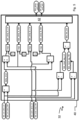
- the brake control system 32 comprises a brake control unit 34.
- the brake control unit 34 receives as input a first external brake demand Brk_ext_dmd_1 and a second external brake demand Brk_ext_dmd_2.
- the brake control unit 34 receives a priority demand prio_dmd. Subsequently, the priority demand prio_dmd is illustrated with a lateral longitudinal priority demand Lat_lon_prio_dmd. It should be noted that the invention is not limited thereto.
- the lateral longitudinal priority demand Lat_lon_prio_dmd determines to which amount the first external brake demand Brk_ext_dmd_1 is prioritized over the second external brake demand Brk_ext_dmd_2, when predetermined conditions are met.
- the brake control unit 34 generates a brake command Brk_cmd_i for each group 23 of brake devices or even for each brake device individually (i designates the i-th group or brake device).
- Each brake command Brk_cmd_i is indicative of the braking force, for example, to be exerted by each group 23 or each individual brake device, as the case may be.
- the brake commands Brk_cmd_i are generated such that the first and second external brake demands Brk_ext_dmd_1, Brk_ext_dmd_2 are met simultaneously. If the brake control unit 34 during the braking process determines that it is not possible to achieve the first and second brake demands Brk_ext_dmd_1, Brk_ext_dmd_2 simultaneously, e.g. due to limited available tyre friction, the brake control unit 34 generates each brake command Brk_cmd_i such that the first external brake demand Brk_ext_dmd_1 is prioritized the more over the second external brake demand Brk_ext_dmd_2 the larger the priority demand Lat_lon_prio_dmd is.
- the brake control unit 34 generates the brake commands Brk_cmd_i such that the first external brake demand Brk_ext_dmd_1 is achieved to a larger degree or even met in full as determined by the priority demand Lat_lon_prio_dmd, whereas the second external brake demand Brk_ext_dmd_2 is achieved to a lesser degree or even ignored as determined by the priority demand Lat_lon_prio_dmd.
- the brake control unit 34 may comprise a brake command distributor unit 36.
- the brake command distributor unit 36 receives various internal brake demands, such as the individual brake demands Brk_indiv_dmd_i and the grouped brake demands Brk_group_dmd_i , and the lateral longitudinal priority demand Lat_lon_prio_dmd.
- the brake command distributor unit 36 generates the brake commands Brk_cmd_i based on the various brake demands and the priority demand Lat_lon_prio_dmd.
- the brake control unit 34 may comprise an individual brake control unit 38.
- the individual brake control unit 38 receives the first and second external brake demands Brk_ext_dmd_1, Brk_ext_dmd_2 and generates the individual brake demands Brk_indiv_dmd_i.
- the individual brake demands Brk_indiv_dmd_i are generated to maximize a first brake target, e.g. longitudinal deceleration.
- the individual brake demands Brk_indiv_dmd_i are fed to the brake command distributor unit 36 which processes them in generating the brake commands Brk_cmd_i.
- the brake control unit 34 may comprise a grouped brake control unit 40.
- the grouped brake control unit 40 receives the first and second external brake demands Brk_ext_dmd_1, Brk_ext_dmd_2 and generates the grouped brake demands Brk_group_dmd_i.
- the grouped brake control unit 40 may also receive the individual brake demands Brk_indiv_dmd_i.
- the group brake demands Brk_group_dmd_i are generated to maximize a second brake target, e.g. yaw moment or lateral control.
- the grouped brake demands Brk_group_dmd_i are fed to the brake command distributor unit 36 which processes them in generating the brake commands Brk_cmd_i.
- the brake command distributor 36 processes for each individual brake device an individual brake demand Brk_indiv_dmd_i for that individual brake device and a grouped brake demand Brk_group_dmd_i for the group 23 to which that brake device belongs. Furthermore, the brake command distributor 36 receives the priority demand Lat_lon_prio_dmd. It should be noted that, as described before, the value of the priority demand Lat_lon_prio_dmd is from 0 to 1.
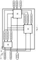
- the grouped brake control unit 40 may include a lead brake toggle switch 42.
- the lead brake toggle switch 42 is configured to determine the brake group demands Brk_group_dmd_i, based on a lead or limiting brake.
- the lead brake toggle switch 42 determines the limiting brake that is going to limit the brake action and outputs the corresponding brake group demands Brk_group_dmd_i, for maximizing the demanded braking action, e.g. the second brake target.
- the grouped brake control unit 40 receives the first and second external brake demands Brk_ext_dmd_1, Brk_ext_dmd_2, which may be brake demands for the LH and RH main landing gears 28, 30, respectively. Subsequently, and for illustration purposes only, the first and second external brake demands Brk_ext_dmd_1, Brk_ext_dmd_2 are referred to as left hand and right hand external brake demands Brk_ext_dmd_LH, Brk_ext_dmd_RH.
- the grouped brake control unit 40 receives a first and second individual brake demand Brk_indiv_dmd_1, Brk_indiv_dmd_2, which also refers to the LH and RH landing gears 28, 30, respectively. Subsequently, and for illustration purposes only, the first and second individual brake demands Brk_indiv_dmd_1, Brk_indiv_dmd_2 are referred to as left hand and right hand individual brake demands Brk_indiv_dmd_LH, Brk_indiv_dmd_RH.
- the grouped brake control unit 40 determines a left hand brake modulation signal Brk_mod_sig_LH and a right hand brake modulation signal Brk_mod_sig_RH.
- the grouped brake control unit 40 may determine a limit brake indication value Brk_lim_ind that indicates the limiting brake.
- the limit brake indication value Brk_lim_ind is determined by subtracting the right hand brake modulation signal Brk_mod_sig_RH from the left hand brake modulation signal Brk_mod_sig_LH. If the limit brake indication value Brk_lim_ind is greater than zero, the brake associated with the left hand external brake demand Brk_ext_dmd_LH and the left hand individual brake demand Brk_indiv_dmd_Lh, is determined to be the limiting brake otherwise it is the brake associated with the right hand external brake demand Brk_ext_dmd_RH and the right hand individual brake demand Brk_indiv_dmd_RH.
- the brake that is associated with the largest brake modulation signal is determined to be the limiting brake.
- the grouped brake control unit 40 determines a first set of brake demands Brk_dmd_A and a second set of brake demands Brk_dmd_B.
- the first set of brake demands Brk_dmd_A includes a left hand internal brake demand Brk_dmd_A_LH and a right hand internal brake demand Brk_dmd_A_RH.
- the left hand internal brake demand Brk_dmd_A_LH is determined to be the sum of the right hand individual brake demand Brk_indiv_dmd_RH and delta_brk_dmd. If for some reason the sum is smaller than zero, the left hand internal brake demand Brk_dmd_A_LH is set to zero, i.e. there is no negative brake demand.
- the right hand internal brake demand Brk_dmd_A_RH is determined to be the maximum of 0 and the right hand individual brake demand Brk_indiv_dmd_RH, i.e. there is no negative brake demand.
- the second set of brake demands Brk_dmd_B includes a left hand internal brake demand Brk_dmd_B_LH and a right hand internal brake demand Brk_dmd_B_RH.
- the left hand internal brake demand Brk_dmd_B_LH is determined to be the maximum of 0 and the left hand individual brake demand Brk_indiv_dmd_LH, i.e. there is no negative brake demand.
- the lead brake toggle switch 42 receives the sets of internal brake demands Brk_dmd_A and Brk_dmd_B as well as the difference of the brake modulation signals Brk_mod_sig_LH and Brk_mod_sig_RH.
- the lead brake toggle switch 42 determines the limiting brake as previously described. If the left hand brake is determined to be the limiting one the lead brake toggle switch 42 outputs the second set of brake demands Brk_dmd_B as the left hand and right hand brake group demand Brk_group_dmd_LH, Brk_group_dmd_RH for further processing by the brake command distributor unit 36.
- the lead brake toggle switch 42 outputs the first set of brake demands Brk_dmd_A as the left hand and right hand brake group demand Brk_group_dmd_LH, Brk_group_dmd_RH for further processing by the brake command distributor unit 36.
- the invention proposes a brake control method for controlling a braking system of a vehicle, preferably an aircraft (10).
- the aircraft (10) has a plurality of brake device groups (23), and a brake control unit (34) receives a plurality of external brake demand signals each of which determines a brake target, such as longitudinal deceleration and/or lateral control.
- a priority demand signal that controls priority controls the priority or importance of the first brake target over the second brake target. If it is not possible to achieve longitudinal deceleration and lateral control authority simultaneously, one of the two is prioritized with an amount that is given by the priority demand signal.
Landscapes
- Engineering & Computer Science (AREA)
- Transportation (AREA)
- Mechanical Engineering (AREA)
- Aviation & Aerospace Engineering (AREA)
- Regulating Braking Force (AREA)
Priority Applications (3)
| Application Number | Priority Date | Filing Date | Title |
|---|---|---|---|
| EP22382210.7A EP4242076B1 (fr) | 2022-03-07 | 2022-03-07 | Procédé de commande de freinage et dispositif de commande de freinage pour un véhicule, tel qu'un aéronef |
| ES22382210T ES3010541T3 (en) | 2022-03-07 | 2022-03-07 | Brake control method and brake control device for a vehicle, such as an aircraft |
| PCT/EP2023/053865 WO2023169795A1 (fr) | 2022-03-07 | 2023-02-16 | Procédé de commande de frein et dispositif de commande de frein pour un véhicule, tel qu'un aéronef |
Applications Claiming Priority (1)
| Application Number | Priority Date | Filing Date | Title |
|---|---|---|---|
| EP22382210.7A EP4242076B1 (fr) | 2022-03-07 | 2022-03-07 | Procédé de commande de freinage et dispositif de commande de freinage pour un véhicule, tel qu'un aéronef |
Publications (2)
| Publication Number | Publication Date |
|---|---|
| EP4242076A1 true EP4242076A1 (fr) | 2023-09-13 |
| EP4242076B1 EP4242076B1 (fr) | 2024-12-04 |
Family
ID=80683856
Family Applications (1)
| Application Number | Title | Priority Date | Filing Date |
|---|---|---|---|
| EP22382210.7A Active EP4242076B1 (fr) | 2022-03-07 | 2022-03-07 | Procédé de commande de freinage et dispositif de commande de freinage pour un véhicule, tel qu'un aéronef |
Country Status (3)
| Country | Link |
|---|---|
| EP (1) | EP4242076B1 (fr) |
| ES (1) | ES3010541T3 (fr) |
| WO (1) | WO2023169795A1 (fr) |
Citations (9)
| Publication number | Priority date | Publication date | Assignee | Title |
|---|---|---|---|---|
| US5707118A (en) | 1995-09-15 | 1998-01-13 | Alliedsignal, Inc. | Velocity based brake control system with directional stability |
| US5975656A (en) * | 1997-08-18 | 1999-11-02 | Westinghouse Air Brake Company | Universal wheel slip force control logic |
| JP2002104278A (ja) * | 2000-09-27 | 2002-04-10 | Suzuki Motor Corp | リーン式自動三輪車 |
| JP2007097378A (ja) * | 2005-09-30 | 2007-04-12 | Toshiba Corp | 自動列車運転装置 |
| US7775607B2 (en) | 2004-11-11 | 2010-08-17 | Hydro-Aire, Inc. | Antiskid control—combined paired/individual wheel control logic |
| EP1864878B1 (fr) | 2006-06-02 | 2011-12-21 | Goodrich Corporation | Commande de frein différentiel et vitesse de roue moyenne pondérée pour système de commande de frein |
| US20150301531A1 (en) * | 2012-11-16 | 2015-10-22 | Airbus Operations Limited | Landing gear force and moment distributor |
| EP2974957A1 (fr) | 2014-07-18 | 2016-01-20 | Airbus Operations Limited | Freinage différentiel de roues de train d'atterrissage d'aéronef |
| US20190016326A1 (en) * | 2017-07-11 | 2019-01-17 | Goodrich Corporation | Brake handle for emergency electric braking |
-
2022
- 2022-03-07 ES ES22382210T patent/ES3010541T3/es active Active
- 2022-03-07 EP EP22382210.7A patent/EP4242076B1/fr active Active
-
2023
- 2023-02-16 WO PCT/EP2023/053865 patent/WO2023169795A1/fr not_active Ceased
Patent Citations (11)
| Publication number | Priority date | Publication date | Assignee | Title |
|---|---|---|---|---|
| US5707118A (en) | 1995-09-15 | 1998-01-13 | Alliedsignal, Inc. | Velocity based brake control system with directional stability |
| US5975656A (en) * | 1997-08-18 | 1999-11-02 | Westinghouse Air Brake Company | Universal wheel slip force control logic |
| JP2002104278A (ja) * | 2000-09-27 | 2002-04-10 | Suzuki Motor Corp | リーン式自動三輪車 |
| US7775607B2 (en) | 2004-11-11 | 2010-08-17 | Hydro-Aire, Inc. | Antiskid control—combined paired/individual wheel control logic |
| US8147006B2 (en) | 2004-11-11 | 2012-04-03 | Hydro-Aire, Inc., A Subsidiary Of Crane Co. | Antiskid control—combined paired/individual wheel control logic |
| JP2007097378A (ja) * | 2005-09-30 | 2007-04-12 | Toshiba Corp | 自動列車運転装置 |
| EP1864878B1 (fr) | 2006-06-02 | 2011-12-21 | Goodrich Corporation | Commande de frein différentiel et vitesse de roue moyenne pondérée pour système de commande de frein |
| US20150301531A1 (en) * | 2012-11-16 | 2015-10-22 | Airbus Operations Limited | Landing gear force and moment distributor |
| EP2920070B1 (fr) | 2012-11-16 | 2018-03-14 | Airbus Operations Limited | Dstributeur de forces et de couple de braquage pour système de propulsion ou de freinage d'un atterrisseur d'aéronef |
| EP2974957A1 (fr) | 2014-07-18 | 2016-01-20 | Airbus Operations Limited | Freinage différentiel de roues de train d'atterrissage d'aéronef |
| US20190016326A1 (en) * | 2017-07-11 | 2019-01-17 | Goodrich Corporation | Brake handle for emergency electric braking |
Also Published As
| Publication number | Publication date |
|---|---|
| WO2023169795A1 (fr) | 2023-09-14 |
| ES3010541T3 (en) | 2025-04-03 |
| EP4242076B1 (fr) | 2024-12-04 |
Similar Documents
| Publication | Publication Date | Title |
|---|---|---|
| CN111114761B (zh) | 飞行器起落架纵向力控制 | |
| EP2920070B1 (fr) | Dstributeur de forces et de couple de braquage pour système de propulsion ou de freinage d'un atterrisseur d'aéronef | |
| CN106335632B (zh) | 用于飞行器的制动控制系统 | |
| EP2944566B1 (fr) | Système et procédé pour optimiser des charges sur l'empennage horizontal | |
| CN111483588B (zh) | 飞行器起落架轮的差动制动 | |
| EP3434586B1 (fr) | Fonctions d'atténuation d'une charge de freinage | |
| CN106335634B (zh) | 飞行器及其转向系统、转向方法和转向系统控制器 | |
| EP4194288B1 (fr) | Systèmes et procédés de freinage antipatinage d'aéronef | |
| US9126572B2 (en) | Method of managing the braking of an aircraft | |
| EP3403891B1 (fr) | Commande de pédale de décélération pour systèmes de freinage | |
| EP4242076B1 (fr) | Procédé de commande de freinage et dispositif de commande de freinage pour un véhicule, tel qu'un aéronef | |
| EP4325316B1 (fr) | Procédé et appareil de commande de manoeuvres au sol d'un aéronef | |
| EP2949527B1 (fr) | Système d'auto-freinage avec ajustement de trajectoire de course | |
| CN110398977A (zh) | 一种无人机副翼减速系统及方法 |
Legal Events
| Date | Code | Title | Description |
|---|---|---|---|
| PUAI | Public reference made under article 153(3) epc to a published international application that has entered the european phase |
Free format text: ORIGINAL CODE: 0009012 |
|
| STAA | Information on the status of an ep patent application or granted ep patent |
Free format text: STATUS: THE APPLICATION HAS BEEN PUBLISHED |
|
| AK | Designated contracting states |
Kind code of ref document: A1 Designated state(s): AL AT BE BG CH CY CZ DE DK EE ES FI FR GB GR HR HU IE IS IT LI LT LU LV MC MK MT NL NO PL PT RO RS SE SI SK SM TR |
|
| STAA | Information on the status of an ep patent application or granted ep patent |
Free format text: STATUS: REQUEST FOR EXAMINATION WAS MADE |
|
| 17P | Request for examination filed |
Effective date: 20240313 |
|
| RBV | Designated contracting states (corrected) |
Designated state(s): AL AT BE BG CH CY CZ DE DK EE ES FI FR GB GR HR HU IE IS IT LI LT LU LV MC MK MT NL NO PL PT RO RS SE SI SK SM TR |
|
| GRAP | Despatch of communication of intention to grant a patent |
Free format text: ORIGINAL CODE: EPIDOSNIGR1 |
|
| STAA | Information on the status of an ep patent application or granted ep patent |
Free format text: STATUS: GRANT OF PATENT IS INTENDED |
|
| INTG | Intention to grant announced |
Effective date: 20240724 |
|
| GRAS | Grant fee paid |
Free format text: ORIGINAL CODE: EPIDOSNIGR3 |
|
| GRAA | (expected) grant |
Free format text: ORIGINAL CODE: 0009210 |
|
| STAA | Information on the status of an ep patent application or granted ep patent |
Free format text: STATUS: THE PATENT HAS BEEN GRANTED |
|
| AK | Designated contracting states |
Kind code of ref document: B1 Designated state(s): AL AT BE BG CH CY CZ DE DK EE ES FI FR GB GR HR HU IE IS IT LI LT LU LV MC MK MT NL NO PL PT RO RS SE SI SK SM TR |
|
| REG | Reference to a national code |
Ref country code: CH Ref legal event code: EP |
|
| REG | Reference to a national code |
Ref country code: DE Ref legal event code: R096 Ref document number: 602022008402 Country of ref document: DE |
|
| REG | Reference to a national code |
Ref country code: IE Ref legal event code: FG4D |
|
| REG | Reference to a national code |
Ref country code: DE Ref legal event code: R081 Ref document number: 602022008402 Country of ref document: DE Owner name: AIRBUS DEFENCE AND SPACE GMBH, DE Free format text: FORMER OWNER: ANMELDERANGABEN UNKLAR / UNVOLLSTAENDIG, 80297 MUENCHEN, DE Ref country code: DE Ref legal event code: R081 Ref document number: 602022008402 Country of ref document: DE Owner name: AIRBUS DEFENCE AND SPACE, S.A., GETAFE, ES Free format text: FORMER OWNER: ANMELDERANGABEN UNKLAR / UNVOLLSTAENDIG, 80297 MUENCHEN, DE |
|
| REG | Reference to a national code |
Ref country code: LT Ref legal event code: MG9D |
|
| REG | Reference to a national code |
Ref country code: NL Ref legal event code: MP Effective date: 20241204 |
|
| PG25 | Lapsed in a contracting state [announced via postgrant information from national office to epo] |
Ref country code: HR Free format text: LAPSE BECAUSE OF FAILURE TO SUBMIT A TRANSLATION OF THE DESCRIPTION OR TO PAY THE FEE WITHIN THE PRESCRIBED TIME-LIMIT Effective date: 20241204 |
|
| PGFP | Annual fee paid to national office [announced via postgrant information from national office to epo] |
Ref country code: DE Payment date: 20250319 Year of fee payment: 4 |
|
| PG25 | Lapsed in a contracting state [announced via postgrant information from national office to epo] |
Ref country code: FI Free format text: LAPSE BECAUSE OF FAILURE TO SUBMIT A TRANSLATION OF THE DESCRIPTION OR TO PAY THE FEE WITHIN THE PRESCRIBED TIME-LIMIT Effective date: 20241204 |
|
| PG25 | Lapsed in a contracting state [announced via postgrant information from national office to epo] |
Ref country code: BG Free format text: LAPSE BECAUSE OF FAILURE TO SUBMIT A TRANSLATION OF THE DESCRIPTION OR TO PAY THE FEE WITHIN THE PRESCRIBED TIME-LIMIT Effective date: 20241204 |
|
| PG25 | Lapsed in a contracting state [announced via postgrant information from national office to epo] |
Ref country code: NO Free format text: LAPSE BECAUSE OF FAILURE TO SUBMIT A TRANSLATION OF THE DESCRIPTION OR TO PAY THE FEE WITHIN THE PRESCRIBED TIME-LIMIT Effective date: 20250304 |
|
| PG25 | Lapsed in a contracting state [announced via postgrant information from national office to epo] |
Ref country code: LV Free format text: LAPSE BECAUSE OF FAILURE TO SUBMIT A TRANSLATION OF THE DESCRIPTION OR TO PAY THE FEE WITHIN THE PRESCRIBED TIME-LIMIT Effective date: 20241204 Ref country code: GR Free format text: LAPSE BECAUSE OF FAILURE TO SUBMIT A TRANSLATION OF THE DESCRIPTION OR TO PAY THE FEE WITHIN THE PRESCRIBED TIME-LIMIT Effective date: 20250305 |
|
| PGFP | Annual fee paid to national office [announced via postgrant information from national office to epo] |
Ref country code: FR Payment date: 20250326 Year of fee payment: 4 |
|
| PG25 | Lapsed in a contracting state [announced via postgrant information from national office to epo] |
Ref country code: RS Free format text: LAPSE BECAUSE OF FAILURE TO SUBMIT A TRANSLATION OF THE DESCRIPTION OR TO PAY THE FEE WITHIN THE PRESCRIBED TIME-LIMIT Effective date: 20250304 |
|
| PG25 | Lapsed in a contracting state [announced via postgrant information from national office to epo] |
Ref country code: NL Free format text: LAPSE BECAUSE OF FAILURE TO SUBMIT A TRANSLATION OF THE DESCRIPTION OR TO PAY THE FEE WITHIN THE PRESCRIBED TIME-LIMIT Effective date: 20241204 |
|
| REG | Reference to a national code |
Ref country code: AT Ref legal event code: MK05 Ref document number: 1747871 Country of ref document: AT Kind code of ref document: T Effective date: 20241204 |
|
| PG25 | Lapsed in a contracting state [announced via postgrant information from national office to epo] |
Ref country code: SM Free format text: LAPSE BECAUSE OF FAILURE TO SUBMIT A TRANSLATION OF THE DESCRIPTION OR TO PAY THE FEE WITHIN THE PRESCRIBED TIME-LIMIT Effective date: 20241204 |
|
| PG25 | Lapsed in a contracting state [announced via postgrant information from national office to epo] |
Ref country code: PL Free format text: LAPSE BECAUSE OF FAILURE TO SUBMIT A TRANSLATION OF THE DESCRIPTION OR TO PAY THE FEE WITHIN THE PRESCRIBED TIME-LIMIT Effective date: 20241204 |
|
| PGFP | Annual fee paid to national office [announced via postgrant information from national office to epo] |
Ref country code: ES Payment date: 20250429 Year of fee payment: 4 |
|
| PG25 | Lapsed in a contracting state [announced via postgrant information from national office to epo] |
Ref country code: IS Free format text: LAPSE BECAUSE OF FAILURE TO SUBMIT A TRANSLATION OF THE DESCRIPTION OR TO PAY THE FEE WITHIN THE PRESCRIBED TIME-LIMIT Effective date: 20250404 |
|
| PG25 | Lapsed in a contracting state [announced via postgrant information from national office to epo] |
Ref country code: PT Free format text: LAPSE BECAUSE OF FAILURE TO SUBMIT A TRANSLATION OF THE DESCRIPTION OR TO PAY THE FEE WITHIN THE PRESCRIBED TIME-LIMIT Effective date: 20250404 |
|
| PG25 | Lapsed in a contracting state [announced via postgrant information from national office to epo] |
Ref country code: EE Free format text: LAPSE BECAUSE OF FAILURE TO SUBMIT A TRANSLATION OF THE DESCRIPTION OR TO PAY THE FEE WITHIN THE PRESCRIBED TIME-LIMIT Effective date: 20241204 |
|
| PG25 | Lapsed in a contracting state [announced via postgrant information from national office to epo] |
Ref country code: RO Free format text: LAPSE BECAUSE OF FAILURE TO SUBMIT A TRANSLATION OF THE DESCRIPTION OR TO PAY THE FEE WITHIN THE PRESCRIBED TIME-LIMIT Effective date: 20241204 Ref country code: AT Free format text: LAPSE BECAUSE OF FAILURE TO SUBMIT A TRANSLATION OF THE DESCRIPTION OR TO PAY THE FEE WITHIN THE PRESCRIBED TIME-LIMIT Effective date: 20241204 |
|
| PG25 | Lapsed in a contracting state [announced via postgrant information from national office to epo] |
Ref country code: SK Free format text: LAPSE BECAUSE OF FAILURE TO SUBMIT A TRANSLATION OF THE DESCRIPTION OR TO PAY THE FEE WITHIN THE PRESCRIBED TIME-LIMIT Effective date: 20241204 |
|
| PG25 | Lapsed in a contracting state [announced via postgrant information from national office to epo] |
Ref country code: CZ Free format text: LAPSE BECAUSE OF FAILURE TO SUBMIT A TRANSLATION OF THE DESCRIPTION OR TO PAY THE FEE WITHIN THE PRESCRIBED TIME-LIMIT Effective date: 20241204 |
|
| PG25 | Lapsed in a contracting state [announced via postgrant information from national office to epo] |
Ref country code: IT Free format text: LAPSE BECAUSE OF FAILURE TO SUBMIT A TRANSLATION OF THE DESCRIPTION OR TO PAY THE FEE WITHIN THE PRESCRIBED TIME-LIMIT Effective date: 20241204 |
|
| REG | Reference to a national code |
Ref country code: DE Ref legal event code: R097 Ref document number: 602022008402 Country of ref document: DE |
|
| PG25 | Lapsed in a contracting state [announced via postgrant information from national office to epo] |
Ref country code: SE Free format text: LAPSE BECAUSE OF FAILURE TO SUBMIT A TRANSLATION OF THE DESCRIPTION OR TO PAY THE FEE WITHIN THE PRESCRIBED TIME-LIMIT Effective date: 20241204 |
|
| PG25 | Lapsed in a contracting state [announced via postgrant information from national office to epo] |
Ref country code: DK Free format text: LAPSE BECAUSE OF FAILURE TO SUBMIT A TRANSLATION OF THE DESCRIPTION OR TO PAY THE FEE WITHIN THE PRESCRIBED TIME-LIMIT Effective date: 20241204 |
|
| PLBE | No opposition filed within time limit |
Free format text: ORIGINAL CODE: 0009261 |
|
| STAA | Information on the status of an ep patent application or granted ep patent |
Free format text: STATUS: NO OPPOSITION FILED WITHIN TIME LIMIT |
|
| PG25 | Lapsed in a contracting state [announced via postgrant information from national office to epo] |
Ref country code: MC Free format text: LAPSE BECAUSE OF FAILURE TO SUBMIT A TRANSLATION OF THE DESCRIPTION OR TO PAY THE FEE WITHIN THE PRESCRIBED TIME-LIMIT Effective date: 20241204 |
|
| REG | Reference to a national code |
Ref country code: CH Ref legal event code: L10 Free format text: ST27 STATUS EVENT CODE: U-0-0-L10-L00 (AS PROVIDED BY THE NATIONAL OFFICE) Effective date: 20251015 |
|
| REG | Reference to a national code |
Ref country code: CH Ref legal event code: H13 Free format text: ST27 STATUS EVENT CODE: U-0-0-H10-H13 (AS PROVIDED BY THE NATIONAL OFFICE) Effective date: 20251023 |
|
| 26N | No opposition filed |
Effective date: 20250905 |
|
| PG25 | Lapsed in a contracting state [announced via postgrant information from national office to epo] |
Ref country code: LU Free format text: LAPSE BECAUSE OF NON-PAYMENT OF DUE FEES Effective date: 20250307 |
|
| REG | Reference to a national code |
Ref country code: BE Ref legal event code: MM Effective date: 20250331 |
|
| PG25 | Lapsed in a contracting state [announced via postgrant information from national office to epo] |
Ref country code: BE Free format text: LAPSE BECAUSE OF NON-PAYMENT OF DUE FEES Effective date: 20250331 |
|
| PG25 | Lapsed in a contracting state [announced via postgrant information from national office to epo] |
Ref country code: CH Free format text: LAPSE BECAUSE OF NON-PAYMENT OF DUE FEES Effective date: 20250331 |
|
| PG25 | Lapsed in a contracting state [announced via postgrant information from national office to epo] |
Ref country code: IE Free format text: LAPSE BECAUSE OF NON-PAYMENT OF DUE FEES Effective date: 20250307 |