EP2920652B1 - Ausseraxiale digitale heterodyne holografie - Google Patents
Ausseraxiale digitale heterodyne holografie Download PDFInfo
- Publication number
- EP2920652B1 EP2920652B1 EP13802549.9A EP13802549A EP2920652B1 EP 2920652 B1 EP2920652 B1 EP 2920652B1 EP 13802549 A EP13802549 A EP 13802549A EP 2920652 B1 EP2920652 B1 EP 2920652B1
- Authority
- EP
- European Patent Office
- Prior art keywords
- frequency
- wave
- vibration
- signal
- amplitude
- Prior art date
- Legal status (The legal status is an assumption and is not a legal conclusion. Google has not performed a legal analysis and makes no representation as to the accuracy of the status listed.)
- Active
Links
Images



Classifications
-
- G—PHYSICS
- G03—PHOTOGRAPHY; CINEMATOGRAPHY; ANALOGOUS TECHNIQUES USING WAVES OTHER THAN OPTICAL WAVES; ELECTROGRAPHY; HOLOGRAPHY
- G03H—HOLOGRAPHIC PROCESSES OR APPARATUS
- G03H1/00—Holographic processes or apparatus using light, infrared or ultraviolet waves for obtaining holograms or for obtaining an image from them; Details peculiar thereto
- G03H1/0005—Adaptation of holography to specific applications
-
- G—PHYSICS
- G01—MEASURING; TESTING
- G01B—MEASURING LENGTH, THICKNESS OR SIMILAR LINEAR DIMENSIONS; MEASURING ANGLES; MEASURING AREAS; MEASURING IRREGULARITIES OF SURFACES OR CONTOURS
- G01B9/00—Measuring instruments characterised by the use of optical techniques
- G01B9/02—Interferometers
- G01B9/021—Interferometers using holographic techniques
-
- G—PHYSICS
- G01—MEASURING; TESTING
- G01N—INVESTIGATING OR ANALYSING MATERIALS BY DETERMINING THEIR CHEMICAL OR PHYSICAL PROPERTIES
- G01N21/00—Investigating or analysing materials by the use of optical means, i.e. using sub-millimetre waves, infrared, visible or ultraviolet light
- G01N21/17—Systems in which incident light is modified in accordance with the properties of the material investigated
- G01N21/41—Refractivity; Phase-affecting properties, e.g. optical path length
- G01N21/45—Refractivity; Phase-affecting properties, e.g. optical path length using interferometric methods; using Schlieren methods
- G01N21/453—Holographic interferometry
-
- G—PHYSICS
- G03—PHOTOGRAPHY; CINEMATOGRAPHY; ANALOGOUS TECHNIQUES USING WAVES OTHER THAN OPTICAL WAVES; ELECTROGRAPHY; HOLOGRAPHY
- G03H—HOLOGRAPHIC PROCESSES OR APPARATUS
- G03H1/00—Holographic processes or apparatus using light, infrared or ultraviolet waves for obtaining holograms or for obtaining an image from them; Details peculiar thereto
- G03H1/04—Processes or apparatus for producing holograms
- G03H1/0443—Digital holography, i.e. recording holograms with digital recording means
-
- G—PHYSICS
- G03—PHOTOGRAPHY; CINEMATOGRAPHY; ANALOGOUS TECHNIQUES USING WAVES OTHER THAN OPTICAL WAVES; ELECTROGRAPHY; HOLOGRAPHY
- G03H—HOLOGRAPHIC PROCESSES OR APPARATUS
- G03H1/00—Holographic processes or apparatus using light, infrared or ultraviolet waves for obtaining holograms or for obtaining an image from them; Details peculiar thereto
- G03H1/04—Processes or apparatus for producing holograms
- G03H1/08—Synthesising holograms, i.e. holograms synthesized from objects or objects from holograms
- G03H1/0866—Digital holographic imaging, i.e. synthesizing holobjects from holograms
-
- G—PHYSICS
- G03—PHOTOGRAPHY; CINEMATOGRAPHY; ANALOGOUS TECHNIQUES USING WAVES OTHER THAN OPTICAL WAVES; ELECTROGRAPHY; HOLOGRAPHY
- G03H—HOLOGRAPHIC PROCESSES OR APPARATUS
- G03H1/00—Holographic processes or apparatus using light, infrared or ultraviolet waves for obtaining holograms or for obtaining an image from them; Details peculiar thereto
- G03H1/0005—Adaptation of holography to specific applications
- G03H2001/0033—Adaptation of holography to specific applications in hologrammetry for measuring or analysing
-
- G—PHYSICS
- G03—PHOTOGRAPHY; CINEMATOGRAPHY; ANALOGOUS TECHNIQUES USING WAVES OTHER THAN OPTICAL WAVES; ELECTROGRAPHY; HOLOGRAPHY
- G03H—HOLOGRAPHIC PROCESSES OR APPARATUS
- G03H1/00—Holographic processes or apparatus using light, infrared or ultraviolet waves for obtaining holograms or for obtaining an image from them; Details peculiar thereto
- G03H1/04—Processes or apparatus for producing holograms
- G03H1/0443—Digital holography, i.e. recording holograms with digital recording means
- G03H2001/0454—Arrangement for recovering hologram complex amplitude
- G03H2001/0456—Spatial heterodyne, i.e. filtering a Fourier transform of the off-axis record
-
- G—PHYSICS
- G03—PHOTOGRAPHY; CINEMATOGRAPHY; ANALOGOUS TECHNIQUES USING WAVES OTHER THAN OPTICAL WAVES; ELECTROGRAPHY; HOLOGRAPHY
- G03H—HOLOGRAPHIC PROCESSES OR APPARATUS
- G03H1/00—Holographic processes or apparatus using light, infrared or ultraviolet waves for obtaining holograms or for obtaining an image from them; Details peculiar thereto
- G03H1/04—Processes or apparatus for producing holograms
- G03H1/0443—Digital holography, i.e. recording holograms with digital recording means
- G03H2001/0463—Frequency heterodyne, i.e. one beam is frequency shifted
-
- G—PHYSICS
- G03—PHOTOGRAPHY; CINEMATOGRAPHY; ANALOGOUS TECHNIQUES USING WAVES OTHER THAN OPTICAL WAVES; ELECTROGRAPHY; HOLOGRAPHY
- G03H—HOLOGRAPHIC PROCESSES OR APPARATUS
- G03H2210/00—Object characteristics
- G03H2210/62—Moving object
-
- G—PHYSICS
- G03—PHOTOGRAPHY; CINEMATOGRAPHY; ANALOGOUS TECHNIQUES USING WAVES OTHER THAN OPTICAL WAVES; ELECTROGRAPHY; HOLOGRAPHY
- G03H—HOLOGRAPHIC PROCESSES OR APPARATUS
- G03H2227/00—Mechanical components or mechanical aspects not otherwise provided for
- G03H2227/03—Means for moving one component
Definitions
- the present invention relates to a device and an off-axis digital heterodyne holography method, in particular for measuring mechanical vibrations of nanometric amplitudes.
- Holography is a method for reconstructing a three-dimensional (3D) image of an object from the recording of an interference pattern between two coherent waves, a reference wave and a wave scattered by the object to observe.
- the recording is done on a photographic plate. Once the plate has been developed by known photography processes, a hologram is obtained.
- the 3D image is reconstructed by illuminating the hologram with the reference wave, which then produces a wave transmitted directly (order 0) and two diffracted light waves, an object wave (or signal wave) that reconstructs a virtual image of the image.
- object and a conjugate wave which forms a parasitic real image which disturbs the observation of the virtual image and which we seek to suppress.
- digital holography In order to obtain useful quantitative information, a new holography technique has emerged, called digital holography, in which the photographic film is replaced by a two-dimensional optoelectronic detector, for example a CCD camera.
- the acquisition of the interference signal by the detector makes it possible to form an interferogram, that is to say an interference pattern sampled on the two-dimensional detector.
- the fully digital reconstruction process consists of calculate from the interferogram the field of the diffracted wave in a plane of the object, for example by means of a Fresnel transform, which can, for example, include a fast Fourier transform algorithm (FFT according to the abbreviation of the Anglo-Saxon term "Fast Fourrier Transform").
- FFT fast Fourier transform algorithm
- Numerical holography has many advantages over conventional holography, in particular because the reconstructed field of the signal wave is a complex function for accessing the amplitude and phase of the signal wave. It is thus possible to establish the three-dimensional cartography of an object, the study of objects in motion and in particular the study of an object in vibration.
- the field of the signal wave calculated from the interferogram simultaneously comprises the desired diffractive order, the order 0 and the parasite conjugate order. There is therefore an uncertainty about the complex amplitude of the object wave that we are trying to determine.
- One way to suppress the spurious conjugate image and the non-diffracted wave is to introduce a phase shift between the reference wave and the signal wave.
- a technique called digital heterodyne holography is described, especially for the application to the study of objects in vibration.
- the frequency of the reference wave is shifted by a quantity determined as a function of the vibration frequency of the object and the acquisition rate of the detector, for example by means of two acousto-optical modulators. .
- a digital demodulation of the interferogram then makes it possible to suppress the components due to the order 0 and the conjugate order.
- the invention proposes a method and an off-axis heterodyne holography device which, compared to known technologies, makes it possible to access higher signal-to-noise ratios and thus to improve the accuracy of measurement, especially on vibration amplitudes below one nanometer.
- ⁇ 1 and ⁇ 2 are of different standards to avoid the effects of crosstalk (or "cross-talk" according to the English expression) on the frequency spectrum of the optical beats between the frequency components of the reference wave and the signal wave.
- the spectrum of optical beats between the frequency components of the reference wave and the signal wave comprises three lines for frequencies equal to the frequency offsets ⁇ 1 , ⁇ 2 and ⁇ 3 and the calculation for each point the spatial field of the amplitude z of the vibration of the object can be made from the ratio of the amplitudes of the first line and the second line and the ratio of the amplitudes of the first line and the third line.
- the method comprises the emission of a laser wave of frequency ⁇ L and the separation of the laser emission wave to form the illumination wave of the object and a second wave sent to a device Optoelectronic optical frequency shift to form the reference wave, thereby forming illumination and reference waves coherent with each other.
- the vibration of the object may result from the forced excitation of the object at said frequency ⁇ . It is then possible thanks to the method thus described, to determining, in addition to the vibration amplitude, the phase delay between the vibration phase of the object and the phase of the excitation signal, and this from the ratio of the amplitudes of the first line and the second line the frequency spectrum of the optical beats between the frequency components of the reference wave and the signal wave.
- the excitation frequency is continuously variable temporally between a lower excitation frequency ⁇ I and a higher excitation frequency ⁇ F for a duration ( T), the acquisition and processing of interferograms being performed during said duration.
- the variation of the excitation frequency is for example linear between the lower and upper values.
- the method can be applied also in the case of an object having a spectrum of vibration frequencies.
- the acquisition and processing of the interferograms are then performed to obtain the vibration amplitude z of the object at at least one vibration frequency ⁇ contained in the spectrum.
- This method makes it possible, for example, to establish maps of objects in vibration and the determination of resonant points, in particular in the context of laser vibrometry for non-destructive testing.
- the device comprises a laser emission source at the frequency ⁇ L , means for separating the laser emission wave to form the illumination wave of the object and a second wave and a device optical frequency shift optoelectronics, for receiving said second wave to form the reference wave.
- the means for separating the laser wave are fiberized.
- the optoelectronic optical frequency shift device comprises two acousto-optic modulators operating at predetermined frequencies on opposite diffraction orders to form said reference wave.
- the optoelectronic optical frequency shift device comprises a Pockels cell.
- the Pockels cell has the advantage of being less expensive than acousto-optic modulators and does not require complex electronics.
- the device further comprises means for exciting the object at the given vibration frequency ⁇ .
- the two-dimensional optoelectronic detector is a CCD or CMOS type camera.
- the figure 1 illustrates a diagram of an example of digital holography device according to the invention.
- the device is fiberized.
- the device allows the recording and processing of interferograms of an object having at least one vibration frequency ⁇ in order to determine the amplitude and / or the vibration phase.
- vibration frequency ⁇ for express the angular frequency (or pulsation).
- the vibration phase is more precisely defined, in the case of an object subjected to a sinusoidal forced excitation, by the phase delay with respect to the excitation phase.
- the device according to the invention comprises means 3, 7 for generating two waves coherent with each other, an illumination wave of the object W 1 and a reference wave W LO .
- the illumination wave W I and the reference wave W LO exhibit a phase relationship with the non-random illumination wave between them.
- the device further comprises a two-dimensional detector 19 temporal bandwidth ⁇ s.
- the means for generating the device according to the invention comprise a temporally coherent source 3, for example a laser source, emitting a transmission wave W EM having an optical frequency ⁇ L.
- the laser source is, for example, a laser diode emitting at an emission wavelength in the visible or near infrared spectral band, for example a fiber laser diode.
- the generation means of the device according to the invention further comprise a beam splitter 7, making it possible to form, from the emission wave W EM , the illumination wave of the object W I and a second wave W L , each having the optical frequency ⁇ L.
- the beam splitter 7 comprises a fiber coupler for coupling the emitting wave W EM from an optical output fiber of the emission source 3 into two optical fibers 9, 11 to form the beam.
- the illumination wave W I illuminates the object 15 that one wishes to examine, either in reflection or in transmission.
- the wave coming from the object, backscattered or transmitted, is called signal wave in the continuation of the request and designated W s on the figure 1 .
- the vibration of the object resulting for example from a forced excitation of the object at the frequency ⁇ causes a modulation of the phase ⁇ ( t ) of the time portion of the field E of the signal wave W s due to the variation of the optical path between the object 15 in vibration and the detector 19.
- Equation (1) is valid for amplitudes of vibration much lower than the wavelength ⁇ of the emission wave.
- the means of generating the illumination waves of the object and of reference further comprise an optoelectronic frequency shift device 13, intended to receive the second wave W L in order to shift the optical frequency ⁇ L to form the reference wave W LO and a control means 23 of the optoelectronic frequency shift device 13.
- the reference wave W LO offset in frequency is called local oscillator in the following description.
- the offset of the frequency ⁇ L of the reference wave allows a digital demodulation of the interferograms at a demodulation frequency contained in the time bandwidth ⁇ s of the optoelectronic detector, which corresponds to its acquisition rate.
- one chooses ⁇ 1 , ⁇ 2 of different standards to avoid effects of crosstalk (or "cross-talk” according to the Anglo-Saxon expression) on the frequency spectrum of the optical beats between the reference wave and the signal wave.
- the optoelectronic frequency shift device 13 may comprise two acousto-optical modulators (AOM) operating at determined frequencies on opposite diffraction orders to obtain the frequencies shifted from the reference wave.
- the control means 23 may comprise a digital synthesizer making it possible to program the synthesized frequencies of the control signals of the AOMs. The offset frequencies can thus easily be adapted to the vibration frequency ⁇ of the object.
- the optoelectronic frequency shift device 13 may comprise a Pockels cell, enabling the generation of the local oscillator at the desired frequencies. More precisely, the Pockels cell is controlled by a signal intended to create at least two offset frequencies of the reference wave W LO .
- This signal may for example be a linear control voltage sweep with time, whose slope switches sequentially between two values at least once during the acquisition time of an image, the two slopes being the two frequency shifts ⁇ 1 and ⁇ 2 of the dual local oscillator.
- the combining means 21 is arranged so that the two waves interfere with an angle ⁇ of the order of the degree.
- This off-axis assembly makes it possible, during the processing of the recorded interferograms, to perform spatial filtering in the spatial frequency domain k in order to eliminate the conjugate parasite image and the order 0 that appear during the reconstruction of the holograms. Thanks to the selection of frequencies of the local oscillator, the interference between the signal wave and the reference wave results in optical beats at frequencies in the temporal bandwidth ⁇ s of the detector 19.
- the digital holography device also comprises means 25 for processing the interferograms recorded by the two-dimensional detector 19.
- FIGS. 2A to 2C schematically illustrate the steps implemented for calculating the holograms of the object, which then makes it possible to access the amplitude z and / or the vibration phase ⁇ of the object.
- a number N of interferograms I p is recorded per time interval by the two-dimensional detector, as illustrated by the Figure 2A .
- N interferograms I p is recorded per time interval by the two-dimensional detector, as illustrated by the Figure 2A .
- the processing means then make it possible to calculate, during a reconstruction step, a hologram of the object from each recorded inter
- Each hologram is thus defined by the complex amplitude of the signal wave in the given spatial field of the object.
- an off-axis part H p (so-called off-axis) of the images ⁇ p is retained in the following, as illustrated in FIG. Figure 2B , the off-axis holograms H p being obtained by digital filtering in the spatial frequency space, to keep only the useful diffraction order during the reconstruction.
- H ( ⁇ k ) in frequency of the optical beats between the frequency components of the reference wave W LO and the signal wave W S for each point of the field.
- H ( ⁇ 1 ⁇ s ) K ⁇ 0 ⁇ * L O 1
- H ( ⁇ 2 ⁇ s ) K ⁇ 1 ⁇ * LO 2 .
- FIGS. 3A to 3C show diagrams representing measured frequency spectra of the amplitude E of the signal wave field W s ( figure 3A ), the amplitude E LO of the field of the reference wave W LO ( figure 3B ) and optical beats between the frequency components of the reference wave W LO and the signal wave W S for a given point of the field ( figure 3C ) in an exemplary implementation.
- the emission source is a laser diode operating at 532 nm.
- the signal and reference waves are combined on the detector at an angle of a few degrees.
- a variable voltage between 10 -2 V and 10 V is applied to the piezoelectric actuator to vary the vibration amplitude.
- a series 256 interferograms I p is acquired by the CCD camera and then processed according to the method described above.
- FIGS. 3A and 3B illustrate the frequency spectra of the signal wave and the reference wave (local oscillator).
- of the signal wave (brought back to the frequency 0) and the lateral bands
- each interferogram I p formed in the plane of the detector has an expression given by equation (3) above.
- the detector records the non-shifted component
- the amplitude of the line A is proportional to ⁇ LO 2 * ⁇ 1 and the amplitude of the line B is proportional to ⁇ LO 1 * ⁇ 0 , the line C corresponding to the static contribution to the spectrum of the beats.
- the three contributions A, B and C are within the time bandwidth ⁇ s of the detector, the other contributions of equation (3) are not detected.
- equation (6) it is possible to access the vibration amplitude z of the object by calculating the ratio between the amplitude of the lines A and B.
- the ratio of the complex amplitudes ⁇ 0 and ⁇ 1 is spatially averaged over the entire image of the object.
- the applicant has shown that the simultaneous acquisition of the amplitudes of the sidebands represented by the lines A and B on the figure 3C allowed an excellent signal-to-noise ratio in the measurement of amplitude and phase of vibration.
- the signal-to-noise ratio can be further improved by carrying out a spatial averaging of the spatial measurement field or a part of the spatial measurement field, of the ratio of the amplitudes of the measured lines.
- the figure 4 shows, according to the above embodiment, measurement results of the vibration amplitude z of the piezoelectric actuator when the supply voltage of the actuator varies. More precisely, the points 40 represent the vibration amplitude values in meters (m) measured with the method using the dual local oscillator as described above, as a function of the voltage supply voltage in Volts (V) of the piezoelectric actuator.
- the diagram also shows the result of measurements of the vibration amplitude 42 carried out according to a method of the prior art, in which the non-shifted component and the first shifted component of the signal wave have been recorded from sequentially, with the other measurement conditions equal to those of the method according to the invention (same object, frequency offsets ⁇ 1 and ⁇ 2 , supply voltages).
- the method according to the present invention makes it possible to access vibration amplitudes of the object of the order of angstrom (10 -10 m), whereas the minimum amplitude accessible by the method of the prior art is of the order of 10 nm (10 -8 m).
- experimental measuring points 40 as well as the result of the theoretical calculation (continuous line 44) using equation (6) are represented.
- the use of at least two offset frequencies for the reference wave W LO makes it possible to obtain a perfect phase agreement at each point between the hologram corresponding to the non-frequency shifted component ⁇ 0 and the hologram corresponding to the component shifted in frequency ⁇ ⁇ 1 . Thanks to this phase agreement, the signal-to-signal noise can be increased compared to a measurement of z using two sequential frequency offsets, and vibrations of the object of very low amplitude are accessible to the measurement.
- the applicant has experimentally shown the feasibility of spatial mapping of vibration amplitude and vibration phase, with excellent accuracy.
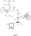
- the experimental setup is represented on the figure 5 .
- the object used is a lamellophone with metal lamellae whose lamellae have resonant frequencies that are different from each other, in particular as a function of the mass and the length of each lamella.
- a piezoelectric actuator is used to excite the lamellophone lamellae at a variable vibration frequency ⁇ .
- the elements used for the experimental setup of the figure 5 may be substantially identical to those described with reference to the figure 1 .
- the reference wave W LO local oscillator
- the reference wave W LO has three offset frequencies ⁇ 1 , ⁇ 2 and ⁇ 3 shifted by the transmission frequency ⁇ L respectively by one quantity ⁇ 1 , ⁇ 2 and ⁇ 3 , the frequency offsets being chosen to allow demodulation of the interferograms in the temporal spectral band ⁇ s of the detector, for example a CCD camera.
- the camera makes it possible to acquire at its acquisition frequency ⁇ s a series of N interferograms which are processed in such a way as to obtain a frequency spectrum of the optical beats between the local oscillator and the wave signal.
- each lamellophone lamella is successively vibrated at its resonant frequency.
- the frequency offsets ⁇ 1 ⁇ s , ⁇ 2 ⁇ s and ⁇ 3 ⁇ s are respectively - 5 Hz, - 2.5 Hz and - 7.5 Hz.
- Figures 6A to 6D show the frequency components of holograms H ( ⁇ k ) as defined by equation (4) above and computed over all points of the object. More specifically, the Figure 6A shows the non-shifted component
- the Figures 6B to 6D represent the frequency component
- a qualitative observation of the resonance frequencies of the different lamellae is thus demonstrated, by varying the excitation frequency of the lamellophone and adapting an offset frequency of the local oscillator to the excitation frequency.
- a quantitative measurement of the vibration amplitude z and the phase retardation ⁇ at a point of the object can then be made from the complex amplitudes of the different spectral lines. in frequency of the holograms measured simultaneously thanks to the multiple offset frequencies of the local oscillator.
- the local oscillator has 3 offset frequencies and the vibration amplitude z and the phase delay ⁇ can be deduced from two of the three lines
- of the frequency spectrum of holograms, or of the three lines of the frequency spectrum of holograms, for example by the equations: z ⁇ ⁇ 4 ⁇ H ⁇ ⁇ 2 ⁇ s H ⁇ ⁇ 1 ⁇ s + H ⁇ ⁇ 3 ⁇ s H ⁇ ⁇ 1 ⁇ s , ⁇ - ⁇ 0 1 2 arg H ⁇ ⁇ 2 ⁇ s H ⁇ ⁇ 1 ⁇ s + arg H ⁇ ⁇ 1 ⁇ s H ⁇ ⁇ 3 ⁇ s , taking into account equations (1), (2) and (5).
- the figure 7 shows the amplitude of vibration of the long lamellophone lamella (indicated by the arrow in the Figure 6B ) according to the frequency of excitation ⁇ . At the resonant frequency of 541 Hz of this lamella, the amplitude of vibration 50 is maximum.
- a continuous temporal variation of the excitation frequency (“chirp” according to the English expression Saxon) is applied simultaneously to the excitation signal of the object and to one of the frequency offsets ⁇ n of the reference wave.
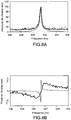
- the Figures 8A and 8B show experimental results obtained with an experimental setup according to the example of the figure 5 as described above.
- N 8 interferograms were acquired at a rate of 20 Hz by the CCD camera, and processed according to the method of the present invention.
- the amplitude of vibration of the long lamella of the lamellophone as a function of the excitation frequency ⁇ is shown on the figure 8A , where the amplitude of vibration is maximum at the resonance frequency of the lamella considered.
- the Figure 8B represents the phase shift ⁇ - ⁇ 0 as a function of the excitation frequency.
- the curve shows a phase jump of ⁇ at the resonance frequency.
- the present invention also applies to the study of the vibration and more particularly of the resonance frequencies of objects having vibration spectra, by example in the context of non-destructive testing.
- the precise measurements of the amplitude of vibration and of the phase retardation as described above can make it possible to analyze with precision in particular the resonances of the object.
- heterodyne off-axis holography method and device comprises various alternatives, modifications and improvements which will become apparent to those skilled in the art, it being understood that these various variants, modifications and improvements are within the scope of the invention, as defined by the following claims.
Landscapes
- Physics & Mathematics (AREA)
- General Physics & Mathematics (AREA)
- Theoretical Computer Science (AREA)
- Computing Systems (AREA)
- Engineering & Computer Science (AREA)
- Biochemistry (AREA)
- Analytical Chemistry (AREA)
- General Health & Medical Sciences (AREA)
- Immunology (AREA)
- Pathology (AREA)
- Chemical & Material Sciences (AREA)
- Life Sciences & Earth Sciences (AREA)
- Health & Medical Sciences (AREA)
- Measurement Of Mechanical Vibrations Or Ultrasonic Waves (AREA)
- Holo Graphy (AREA)
Claims (16)
- Digitales Holographie-Verfahren zum Detektieren der Amplitude z der Vibration eines Objekts (15) bei mindestens einer Vibrationsfrequenz co, umfassend:- das Erzeugen einer Laserwelle der Frequenz ωL zur Beleuchtung des Objekts (WI) und einer Referenzwelle (WLO), die zu der Beleuchtungswelle (WI) kohärent ist,- das Erfassen mittels eines zweidimensionalen optoelektronischen Sensors (19) der zeitlichen Bandbreite ωS einer Reihe von Interferogrammen, die aus der Interferenz der Referenzwelle (WLO), und einer von dem Objekt (15) stammenden Signalwelle (WS) resultieren, wobei die Signalwelle und die Referenzwelle (WS, WLO) einen Winkelversatz (θ) aufweisen, wobei das Feld der Referenzwelle eine erste Komponente (ELO1) der Frequenz ω1 und mindestens eine zweite Komponente (ELO2) der Frequenz ω2 enthält, wobei die Frequenzen ω1 und ω2 von der Frequenz ωL der Laserwelle um einen bestimmten Betrag δ1, δ2 verschoben sind, mit δ1 = γ1ωS und δ2 = qω + γ2ωS, wobei q eine ganze Zahl und -0,5 ≤ γ1, γ2 ≤ 0,5 ist; und- das Auswerten der Interferogramme, umfassend:- das Berechnen eines Hologramms des Objekts ausgehend von jedem Interferogramm, wobei das Hologramm durch die komplexe Amplitude der Signalwelle in einem vorgegebenen räumlichen Feld einer Ebene des Objekts definiert ist,- das Berechnen der Zeit-Frequenz-Fourier-Transformierten der komplexen Amplituden der Hologramme, um in jedem Punkt des räumlichen Feldes ein Frequenzspektrum der optischen Schwebungen zwischen den Frequenzkomponenten der Referenzwelle und der Signalwelle zu erhalten, wobei das Spektrum der optischen Schwebungen bei Frequenzen, die gleich den Frequenzverschiebungen δ1 und δ2 sind, mindestens zwei Linien (A, B) enthält, und- das Berechnen für jeden Punkt des räumlichen Feldes ausgehend von dem Verhältnis der Amplituden der ersten Linie (A, B) und der zweiten Linie (A, B) der Amplitude z der Vibration des Objekts (15).
- Verfahren nach Anspruch 1, bei dem die Normen von γ1 und γ2 unterschiedlich sind.
- Verfahren nach einem der Ansprüche 1 und 2, umfassend:- das Emittieren einer Laserwelle (WEM) der Frequenz ω, und- das Aufteilen der Laseremissionswelle (WEM), um die Welle zum Beleuchten des Objekts (WI) und eine zweite Welle (WL), die zu einer optoelektronischen Vorrichtung für die optische Frequenzverschiebung (13, 13') gesendet wird, zu bilden, um die Referenzwelle (WLO) zu bilden.
- Verfahren nach einem der vorhergehenden Ansprüche, umfassend die Zwangserregung des Objekts (15) bei der Frequenz co.
- Verfahren nach Anspruch 4, bei dem die Frequenz zum Erregen des Objekts kontinuierlich zeitlich variabel ist zwischen einer unteren Erregerfrequenz ωI und einer oberen Erregerfrequenz ωF über einen gegebenen Zeitraum (T) und bei dem das Erfassen und das Auswerten der Interferogramme während des Zeitraums durchgeführt werden.
- Verfahren nach einem der Ansprüche 4 oder 5, ferner umfassend das Berechnen der Phasenverzögerung zwischen der Vibrationsphase des Objekts und der Phase des Erregersignals ausgehend von dem Verhältnis der Amplituden der ersten Linie (A, B) und der zweiten Linie (A, B).
- Verfahren nach einem der Ansprüche 1 bis 3, bei dem- die Vibration des Objekts (15) ein Frequenzspektrum aufweist; und- das Erfassen und das Auswerten der Interferogramme durchgeführt werden, um die Amplitude z der Vibration des Objekts bei mindestens einer Vibrationsfrequenz co zu erhalten, die in dem Spektrum enthalten ist.
- Verfahren nach einem der vorhergehenden Ansprüche, bei dem das Feld der Referenzwelle (WLO) mindestens eine dritte Komponente (ELO3) der Frequenz ω3 enthält, wobei die Frequenz ω3 von der Frequenz ωL der Laserwelle um einen bestimmten Betrag δ3 = γ3ωS + qω verschoben ist, wobei q eine ganze Zahl und -0,5 ≤ γ3 ≤ 0,5 ist.
- Verfahren nach einem der vorhergehenden Ansprüche, bei dem q = 1 ist.
- Digitale Holographie-Vorrichtung zum Detektieren der Amplitude z der Vibration eines Objekts (15) bei einer Vibrationsfrequenz ω, umfassend:- einen zweidimensionalen optoelektronischen Sensor (19) der zeitlichen Bandbreite ωS,- Mittel zum Erzeugen von zwei Laserwellen (3, 8), die zueinander kohärent sind, einer Laserwelle zur Beleuchtung des Objekts (WI) der Frequenz ωL und einer Referenzwelle (WLO), wobei das Feld der Referenzwelle (WLO) mindestens eine erste und eine zweite Komponente (ELO1, ELO2) der Frequenzen ω1, ω2 aufweist, die von der Frequenz ωL der Laserwelle um einen bestimmten Betrag δ1, δ2 verschoben sind, mit δ1 = γ1ωS und δ2 = qω + γ2ωS, wobei q eine ganze Zahl und -0,5 ≤ γ1, γ2 ≤ 0,5 ist;- Mittel zum Kombinieren (21) der Referenzwelle (WLO) und einer von dem Objekt (15) stammenden Signalwelle WS an dem zweidimensionalen optoelektronischen Sensor (19), wobei die Referenzwelle und die Signalwelle (WLO, WS) einen Winkelversatz (θ) aufweisen, wobei das Erfassen des Interferenzsignals der Signalwelle und der Referenzwelle (WLO, WS) durch den zweidimensionalen optoelektronischen Sensor (19) in einer Reihe von Interferogrammen resultiert; und- Mittel zum Auswerten (23) der Interferogramme, umfassend:- Mittel zum Berechnen von Hologrammen des Objekts, die ausgehend von jedem der Interferogramme erhalten werden, wobei ein Hologramm durch die komplexe Amplitude der Signalwelle (WS) in einem vorgegebenen räumlichen Feld einer Ebene des Objekts (15) definiert ist,- Mittel zum Berechnen der Zeit-Frequenz-Fourier-Transformierten der komplexen Amplituden der Hologramme, um in jedem Punkt des räumlichen Feldes ein Frequenzspektrum der optischen Schwebungen zwischen den Frequenzkomponenten der Referenzwelle (WLO) und der Signalwelle (WS) zu erhalten, wobei das Spektrum der optischen Schwebungen bei Frequenzen, die gleich den Frequenzverschiebungen δ1 und δ2 sind, mindestens zwei Linien (A, B) enthält; und- Mittel zum Berechnen in jedem Punkt des räumlichen Feldes ausgehend von den Amplituden der ersten Linie (A, B) und der zweiten Linie (A, B) der Amplitude z der Vibration des Objekts (15).
- Digitale Holographie-Vorrichtung nach Anspruch 10, umfassend:- eine Quelle für Laser-Emission (3) bei der Frequenz ωL;- Mittel zum Aufteilen (7) der Laseremissionswelle (WEM), um die Welle zum Beleuchten des Objekts (WI) und eine zweite Welle (WL) zu bilden,- eine optoelektronische Vorrichtung für die optische Frequenzverschiebung (13, 13`), die zum Empfangen der zweiten Welle (WL) bestimmt ist, um die Referenzwelle (WLO) zu bilden.
- Digitale Holographie-Vorrichtung nach Anspruch 11, wobei die optoelektronische Vorrichtung für die optische Frequenzverschiebung (13, 13') zwei akusto-optische Modulatoren umfasst, die bei vorbestimmten Frequenzen in entgegengesetzten Beugungsordnungen arbeiten, um die Referenzwelle (WLO) zu bilden.
- Holographie-Vorrichtung nach Anspruch 11, wobei die optoelektronische Vorrichtung für die optische Frequenzverschiebung (13) eine Pockelszelle umfasst.
- Holographie-Vorrichtung nach einem der Ansprüche 11 bis 13, wobei die Mittel zum Aufteilen (7) der Laserwelle gefasert sind.
- Holographie-Vorrichtung nach einem der Ansprüche 10 bis 14, ferner umfassend ein Mittel zum Erregen des Objekts (15) bei der Frequenz co einer gegebenen Vibration.
- Holographie-Vorrichtung nach einem der Ansprüche 10 bis 15, wobei der zweidimensionale optoelektronische Sensor (19) eine Kamera des CCD- oder CMOS-Typs ist.
Applications Claiming Priority (2)
| Application Number | Priority Date | Filing Date | Title |
|---|---|---|---|
| FR1260883A FR2998064B1 (fr) | 2012-11-15 | 2012-11-15 | Holographie heterodyne numerique hors-axe |
| PCT/EP2013/073978 WO2014076251A1 (fr) | 2012-11-15 | 2013-11-15 | Holographie hétérodyne numérique hors-axe |
Publications (2)
| Publication Number | Publication Date |
|---|---|
| EP2920652A1 EP2920652A1 (de) | 2015-09-23 |
| EP2920652B1 true EP2920652B1 (de) | 2017-01-04 |
Family
ID=48224852
Family Applications (1)
| Application Number | Title | Priority Date | Filing Date |
|---|---|---|---|
| EP13802549.9A Active EP2920652B1 (de) | 2012-11-15 | 2013-11-15 | Ausseraxiale digitale heterodyne holografie |
Country Status (4)
| Country | Link |
|---|---|
| US (1) | US9733064B2 (de) |
| EP (1) | EP2920652B1 (de) |
| FR (1) | FR2998064B1 (de) |
| WO (1) | WO2014076251A1 (de) |
Families Citing this family (5)
| Publication number | Priority date | Publication date | Assignee | Title |
|---|---|---|---|---|
| EP3327413B1 (de) * | 2016-11-24 | 2022-04-27 | IMEC vzw | Verfahren, vorrichtung und system zur holografischen wellenfrontmessung |
| FR3064759B1 (fr) * | 2017-03-31 | 2021-02-19 | Centre Nat Rech Scient | Dispositifs et methodes d'imagerie optique par holographie numerique hors axe |
| US11099523B1 (en) * | 2019-05-22 | 2021-08-24 | Lockheed Martin Corporation | Digital holography range Doppler receiver |
| US11768068B2 (en) * | 2019-05-29 | 2023-09-26 | Ramot At Tel-Aviv University Ltd. | System for spatial multiplexing |
| CN112925184B (zh) * | 2021-01-29 | 2022-07-12 | 昆明理工大学 | 基于双声光调制器的全息图像重建方法及重建系统 |
Family Cites Families (1)
| Publication number | Priority date | Publication date | Assignee | Title |
|---|---|---|---|---|
| FR2792082B1 (fr) | 1999-04-06 | 2003-05-30 | Thomson Csf | Dispositif d'holographie numerique |
-
2012
- 2012-11-15 FR FR1260883A patent/FR2998064B1/fr active Active
-
2013
- 2013-11-15 WO PCT/EP2013/073978 patent/WO2014076251A1/fr not_active Ceased
- 2013-11-15 US US14/442,910 patent/US9733064B2/en active Active
- 2013-11-15 EP EP13802549.9A patent/EP2920652B1/de active Active
Non-Patent Citations (1)
| Title |
|---|
| NICOLAS VERRIER ET AL: "Absolute measurement of small-amplitude vibrations by time-averaged heterodyne holography with a dual local oscillator", OPTICS LETTERS, vol. 38, no. 5, 1 March 2013 (2013-03-01), pages 739 - 741, XP055075583, ISSN: 0146-9592, DOI: 10.1364/OL.38.000739 * |
Also Published As
| Publication number | Publication date |
|---|---|
| US20150292858A1 (en) | 2015-10-15 |
| US9733064B2 (en) | 2017-08-15 |
| FR2998064A1 (fr) | 2014-05-16 |
| FR2998064B1 (fr) | 2016-11-25 |
| EP2920652A1 (de) | 2015-09-23 |
| WO2014076251A1 (fr) | 2014-05-22 |
Similar Documents
| Publication | Publication Date | Title |
|---|---|---|
| JP5119193B2 (ja) | 振動計および、物体の光学的測定方法 | |
| EP1364181B1 (de) | Verfahren und einrichtung zur schnellen interferenziellen mikroskopischen abbildung eines objekts | |
| US10488175B2 (en) | Multi wavelength multiplexing for quantitative interferometry | |
| EP3504559B1 (de) | Verfahren zur verarbeitung eines signals aus kohärentem lidar und zugehöriges lidar-system | |
| US10635049B2 (en) | Ellipsometry device and ellipsometry method | |
| EP2920652B1 (de) | Ausseraxiale digitale heterodyne holografie | |
| Abdelsalam et al. | Two-wavelength in-line phase-shifting interferometry based on polarizing separation for accurate surface profiling | |
| EP4256291B1 (de) | Vorrichtung zur breitbandigen spektralanalyse eines signals | |
| EP1043632A1 (de) | Vorrichtung zur digitalen Holographie | |
| Verpillat et al. | Imaging velocities of a vibrating object by stroboscopic sideband holography | |
| FR3064760B1 (fr) | Interferometre holographique numerique a deux faisceaux de reference pour analyser un milieu transparent | |
| EP4004597B1 (de) | Verfahren für kohärente lidar-bildgebung und zugehöriger lidar | |
| EP3044697B1 (de) | Elektronisches verfahren zur extraktion der amplitude und der phase eines signals in einer synchronen detektion und interferometrische anordnung zur durchführung des verfahrens | |
| EP3751278B1 (de) | Akustisch-optisches bildgebungssystem | |
| Verrier et al. | Full field holographic vibrometry at ultimate limits | |
| EP3259624B1 (de) | Messung mittels atominterferometrie mit mehreren arten von atomen | |
| WO2006037880A1 (fr) | Dispositif spectrometrique de coherence | |
| EP4390449A1 (de) | Kohärenter fm-lidar mit verbesserter verarbeitung | |
| Kassem | Interferometric intensity correlation: from sensing to imaging | |
| Abdelsalam et al. | Digital holographic microscopy using partially coherent, instantaneously bright, femtosecond pulse light | |
| EP1509755A2 (de) | Einrichtung und verfahren zur bestimmung des chirpens eines elektrooptischen modulators des mach-zender-typs | |
| FR3032806A1 (fr) | Mesure par interferometrie atomique avec plusieurs especes d'atomes | |
| FR2841649A1 (fr) | Procede et systeme de determination du profil de la phase spectrale ou temporelle d'une impulsion d'energie electromagnetique | |
| Hansche et al. | Widefield laser doppler velocimeter: development and theory. | |
| FR2994600A1 (fr) | Dispositif d'analyse et de reflectivite. |
Legal Events
| Date | Code | Title | Description |
|---|---|---|---|
| PUAI | Public reference made under article 153(3) epc to a published international application that has entered the european phase |
Free format text: ORIGINAL CODE: 0009012 |
|
| 17P | Request for examination filed |
Effective date: 20150609 |
|
| AK | Designated contracting states |
Kind code of ref document: A1 Designated state(s): AL AT BE BG CH CY CZ DE DK EE ES FI FR GB GR HR HU IE IS IT LI LT LU LV MC MK MT NL NO PL PT RO RS SE SI SK SM TR |
|
| AX | Request for extension of the european patent |
Extension state: BA ME |
|
| DAX | Request for extension of the european patent (deleted) | ||
| 17Q | First examination report despatched |
Effective date: 20160316 |
|
| GRAP | Despatch of communication of intention to grant a patent |
Free format text: ORIGINAL CODE: EPIDOSNIGR1 |
|
| INTG | Intention to grant announced |
Effective date: 20160711 |
|
| STAA | Information on the status of an ep patent application or granted ep patent |
Free format text: STATUS: GRANT OF PATENT IS INTENDED |
|
| GRAS | Grant fee paid |
Free format text: ORIGINAL CODE: EPIDOSNIGR3 |
|
| GRAA | (expected) grant |
Free format text: ORIGINAL CODE: 0009210 |
|
| STAA | Information on the status of an ep patent application or granted ep patent |
Free format text: STATUS: THE PATENT HAS BEEN GRANTED |
|
| AK | Designated contracting states |
Kind code of ref document: B1 Designated state(s): AL AT BE BG CH CY CZ DE DK EE ES FI FR GB GR HR HU IE IS IT LI LT LU LV MC MK MT NL NO PL PT RO RS SE SI SK SM TR |
|
| REG | Reference to a national code |
Ref country code: GB Ref legal event code: FG4D Free format text: NOT ENGLISH |
|
| REG | Reference to a national code |
Ref country code: CH Ref legal event code: EP |
|
| REG | Reference to a national code |
Ref country code: AT Ref legal event code: REF Ref document number: 859828 Country of ref document: AT Kind code of ref document: T Effective date: 20170115 |
|
| REG | Reference to a national code |
Ref country code: IE Ref legal event code: FG4D Free format text: LANGUAGE OF EP DOCUMENT: FRENCH |
|
| REG | Reference to a national code |
Ref country code: DE Ref legal event code: R096 Ref document number: 602013016295 Country of ref document: DE |
|
| REG | Reference to a national code |
Ref country code: LT Ref legal event code: MG4D Ref country code: NL Ref legal event code: MP Effective date: 20170104 |
|
| REG | Reference to a national code |
Ref country code: AT Ref legal event code: MK05 Ref document number: 859828 Country of ref document: AT Kind code of ref document: T Effective date: 20170104 |
|
| PG25 | Lapsed in a contracting state [announced via postgrant information from national office to epo] |
Ref country code: NL Free format text: LAPSE BECAUSE OF FAILURE TO SUBMIT A TRANSLATION OF THE DESCRIPTION OR TO PAY THE FEE WITHIN THE PRESCRIBED TIME-LIMIT Effective date: 20170104 |
|
| PG25 | Lapsed in a contracting state [announced via postgrant information from national office to epo] |
Ref country code: IS Free format text: LAPSE BECAUSE OF FAILURE TO SUBMIT A TRANSLATION OF THE DESCRIPTION OR TO PAY THE FEE WITHIN THE PRESCRIBED TIME-LIMIT Effective date: 20170504 Ref country code: GR Free format text: LAPSE BECAUSE OF FAILURE TO SUBMIT A TRANSLATION OF THE DESCRIPTION OR TO PAY THE FEE WITHIN THE PRESCRIBED TIME-LIMIT Effective date: 20170405 Ref country code: FI Free format text: LAPSE BECAUSE OF FAILURE TO SUBMIT A TRANSLATION OF THE DESCRIPTION OR TO PAY THE FEE WITHIN THE PRESCRIBED TIME-LIMIT Effective date: 20170104 Ref country code: HR Free format text: LAPSE BECAUSE OF FAILURE TO SUBMIT A TRANSLATION OF THE DESCRIPTION OR TO PAY THE FEE WITHIN THE PRESCRIBED TIME-LIMIT Effective date: 20170104 Ref country code: NO Free format text: LAPSE BECAUSE OF FAILURE TO SUBMIT A TRANSLATION OF THE DESCRIPTION OR TO PAY THE FEE WITHIN THE PRESCRIBED TIME-LIMIT Effective date: 20170404 Ref country code: LT Free format text: LAPSE BECAUSE OF FAILURE TO SUBMIT A TRANSLATION OF THE DESCRIPTION OR TO PAY THE FEE WITHIN THE PRESCRIBED TIME-LIMIT Effective date: 20170104 |
|
| PG25 | Lapsed in a contracting state [announced via postgrant information from national office to epo] |
Ref country code: BG Free format text: LAPSE BECAUSE OF FAILURE TO SUBMIT A TRANSLATION OF THE DESCRIPTION OR TO PAY THE FEE WITHIN THE PRESCRIBED TIME-LIMIT Effective date: 20170404 Ref country code: ES Free format text: LAPSE BECAUSE OF FAILURE TO SUBMIT A TRANSLATION OF THE DESCRIPTION OR TO PAY THE FEE WITHIN THE PRESCRIBED TIME-LIMIT Effective date: 20170104 Ref country code: LV Free format text: LAPSE BECAUSE OF FAILURE TO SUBMIT A TRANSLATION OF THE DESCRIPTION OR TO PAY THE FEE WITHIN THE PRESCRIBED TIME-LIMIT Effective date: 20170104 Ref country code: AT Free format text: LAPSE BECAUSE OF FAILURE TO SUBMIT A TRANSLATION OF THE DESCRIPTION OR TO PAY THE FEE WITHIN THE PRESCRIBED TIME-LIMIT Effective date: 20170104 Ref country code: PT Free format text: LAPSE BECAUSE OF FAILURE TO SUBMIT A TRANSLATION OF THE DESCRIPTION OR TO PAY THE FEE WITHIN THE PRESCRIBED TIME-LIMIT Effective date: 20170504 Ref country code: PL Free format text: LAPSE BECAUSE OF FAILURE TO SUBMIT A TRANSLATION OF THE DESCRIPTION OR TO PAY THE FEE WITHIN THE PRESCRIBED TIME-LIMIT Effective date: 20170104 Ref country code: SE Free format text: LAPSE BECAUSE OF FAILURE TO SUBMIT A TRANSLATION OF THE DESCRIPTION OR TO PAY THE FEE WITHIN THE PRESCRIBED TIME-LIMIT Effective date: 20170104 Ref country code: RS Free format text: LAPSE BECAUSE OF FAILURE TO SUBMIT A TRANSLATION OF THE DESCRIPTION OR TO PAY THE FEE WITHIN THE PRESCRIBED TIME-LIMIT Effective date: 20170104 |
|
| REG | Reference to a national code |
Ref country code: DE Ref legal event code: R097 Ref document number: 602013016295 Country of ref document: DE |
|
| PG25 | Lapsed in a contracting state [announced via postgrant information from national office to epo] |
Ref country code: EE Free format text: LAPSE BECAUSE OF FAILURE TO SUBMIT A TRANSLATION OF THE DESCRIPTION OR TO PAY THE FEE WITHIN THE PRESCRIBED TIME-LIMIT Effective date: 20170104 Ref country code: CZ Free format text: LAPSE BECAUSE OF FAILURE TO SUBMIT A TRANSLATION OF THE DESCRIPTION OR TO PAY THE FEE WITHIN THE PRESCRIBED TIME-LIMIT Effective date: 20170104 Ref country code: SK Free format text: LAPSE BECAUSE OF FAILURE TO SUBMIT A TRANSLATION OF THE DESCRIPTION OR TO PAY THE FEE WITHIN THE PRESCRIBED TIME-LIMIT Effective date: 20170104 Ref country code: RO Free format text: LAPSE BECAUSE OF FAILURE TO SUBMIT A TRANSLATION OF THE DESCRIPTION OR TO PAY THE FEE WITHIN THE PRESCRIBED TIME-LIMIT Effective date: 20170104 Ref country code: IT Free format text: LAPSE BECAUSE OF FAILURE TO SUBMIT A TRANSLATION OF THE DESCRIPTION OR TO PAY THE FEE WITHIN THE PRESCRIBED TIME-LIMIT Effective date: 20170104 |
|
| PLBE | No opposition filed within time limit |
Free format text: ORIGINAL CODE: 0009261 |
|
| STAA | Information on the status of an ep patent application or granted ep patent |
Free format text: STATUS: NO OPPOSITION FILED WITHIN TIME LIMIT |
|
| PG25 | Lapsed in a contracting state [announced via postgrant information from national office to epo] |
Ref country code: SM Free format text: LAPSE BECAUSE OF FAILURE TO SUBMIT A TRANSLATION OF THE DESCRIPTION OR TO PAY THE FEE WITHIN THE PRESCRIBED TIME-LIMIT Effective date: 20170104 Ref country code: DK Free format text: LAPSE BECAUSE OF FAILURE TO SUBMIT A TRANSLATION OF THE DESCRIPTION OR TO PAY THE FEE WITHIN THE PRESCRIBED TIME-LIMIT Effective date: 20170104 |
|
| REG | Reference to a national code |
Ref country code: FR Ref legal event code: PLFP Year of fee payment: 5 |
|
| PG25 | Lapsed in a contracting state [announced via postgrant information from national office to epo] |
Ref country code: SI Free format text: LAPSE BECAUSE OF FAILURE TO SUBMIT A TRANSLATION OF THE DESCRIPTION OR TO PAY THE FEE WITHIN THE PRESCRIBED TIME-LIMIT Effective date: 20170104 |
|
| PG25 | Lapsed in a contracting state [announced via postgrant information from national office to epo] |
Ref country code: MC Free format text: LAPSE BECAUSE OF FAILURE TO SUBMIT A TRANSLATION OF THE DESCRIPTION OR TO PAY THE FEE WITHIN THE PRESCRIBED TIME-LIMIT Effective date: 20170104 |
|
| PG25 | Lapsed in a contracting state [announced via postgrant information from national office to epo] |
Ref country code: LI Free format text: LAPSE BECAUSE OF NON-PAYMENT OF DUE FEES Effective date: 20171130 Ref country code: CH Free format text: LAPSE BECAUSE OF NON-PAYMENT OF DUE FEES Effective date: 20171130 |
|
| PG25 | Lapsed in a contracting state [announced via postgrant information from national office to epo] |
Ref country code: LU Free format text: LAPSE BECAUSE OF NON-PAYMENT OF DUE FEES Effective date: 20171115 |
|
| REG | Reference to a national code |
Ref country code: BE Ref legal event code: MM Effective date: 20171130 |
|
| REG | Reference to a national code |
Ref country code: IE Ref legal event code: MM4A |
|
| PG25 | Lapsed in a contracting state [announced via postgrant information from national office to epo] |
Ref country code: MT Free format text: LAPSE BECAUSE OF FAILURE TO SUBMIT A TRANSLATION OF THE DESCRIPTION OR TO PAY THE FEE WITHIN THE PRESCRIBED TIME-LIMIT Effective date: 20170104 |
|
| PG25 | Lapsed in a contracting state [announced via postgrant information from national office to epo] |
Ref country code: IE Free format text: LAPSE BECAUSE OF NON-PAYMENT OF DUE FEES Effective date: 20171115 |
|
| PG25 | Lapsed in a contracting state [announced via postgrant information from national office to epo] |
Ref country code: BE Free format text: LAPSE BECAUSE OF NON-PAYMENT OF DUE FEES Effective date: 20171130 |
|
| PG25 | Lapsed in a contracting state [announced via postgrant information from national office to epo] |
Ref country code: HU Free format text: LAPSE BECAUSE OF FAILURE TO SUBMIT A TRANSLATION OF THE DESCRIPTION OR TO PAY THE FEE WITHIN THE PRESCRIBED TIME-LIMIT; INVALID AB INITIO Effective date: 20131115 |
|
| PG25 | Lapsed in a contracting state [announced via postgrant information from national office to epo] |
Ref country code: CY Free format text: LAPSE BECAUSE OF FAILURE TO SUBMIT A TRANSLATION OF THE DESCRIPTION OR TO PAY THE FEE WITHIN THE PRESCRIBED TIME-LIMIT Effective date: 20170104 |
|
| PG25 | Lapsed in a contracting state [announced via postgrant information from national office to epo] |
Ref country code: MK Free format text: LAPSE BECAUSE OF FAILURE TO SUBMIT A TRANSLATION OF THE DESCRIPTION OR TO PAY THE FEE WITHIN THE PRESCRIBED TIME-LIMIT Effective date: 20170104 |
|
| PG25 | Lapsed in a contracting state [announced via postgrant information from national office to epo] |
Ref country code: TR Free format text: LAPSE BECAUSE OF FAILURE TO SUBMIT A TRANSLATION OF THE DESCRIPTION OR TO PAY THE FEE WITHIN THE PRESCRIBED TIME-LIMIT Effective date: 20170104 |
|
| PG25 | Lapsed in a contracting state [announced via postgrant information from national office to epo] |
Ref country code: AL Free format text: LAPSE BECAUSE OF FAILURE TO SUBMIT A TRANSLATION OF THE DESCRIPTION OR TO PAY THE FEE WITHIN THE PRESCRIBED TIME-LIMIT Effective date: 20170104 |
|
| PGFP | Annual fee paid to national office [announced via postgrant information from national office to epo] |
Ref country code: GB Payment date: 20251126 Year of fee payment: 13 |
|
| PGFP | Annual fee paid to national office [announced via postgrant information from national office to epo] |
Ref country code: FR Payment date: 20251127 Year of fee payment: 13 |
|
| PGFP | Annual fee paid to national office [announced via postgrant information from national office to epo] |
Ref country code: DE Payment date: 20251224 Year of fee payment: 13 |