EP4390449A1 - Kohärenter fm-lidar mit verbesserter verarbeitung - Google Patents
Kohärenter fm-lidar mit verbesserter verarbeitung Download PDFInfo
- Publication number
- EP4390449A1 EP4390449A1 EP23219454.8A EP23219454A EP4390449A1 EP 4390449 A1 EP4390449 A1 EP 4390449A1 EP 23219454 A EP23219454 A EP 23219454A EP 4390449 A1 EP4390449 A1 EP 4390449A1
- Authority
- EP
- European Patent Office
- Prior art keywords
- frequency
- signal
- pixel
- laser
- scene
- Prior art date
- Legal status (The legal status is an assumption and is not a legal conclusion. Google has not performed a legal analysis and makes no representation as to the accuracy of the status listed.)
- Pending
Links
- 230000001427 coherent effect Effects 0.000 title claims abstract description 37
- 230000003287 optical effect Effects 0.000 claims abstract description 82
- 230000005855 radiation Effects 0.000 claims abstract description 22
- 238000001514 detection method Methods 0.000 claims abstract description 15
- 238000003384 imaging method Methods 0.000 claims abstract description 10
- 230000035559 beat frequency Effects 0.000 claims description 21
- 238000005259 measurement Methods 0.000 claims description 17
- 238000000034 method Methods 0.000 claims description 10
- 239000011159 matrix material Substances 0.000 claims description 8
- 230000010363 phase shift Effects 0.000 description 5
- 230000010354 integration Effects 0.000 description 4
- 239000000463 material Substances 0.000 description 4
- 238000012634 optical imaging Methods 0.000 description 4
- 241001080024 Telles Species 0.000 description 2
- 238000012550 audit Methods 0.000 description 2
- 230000008901 benefit Effects 0.000 description 2
- 230000007423 decrease Effects 0.000 description 2
- 230000002452 interceptive effect Effects 0.000 description 2
- 230000010355 oscillation Effects 0.000 description 2
- 238000005215 recombination Methods 0.000 description 2
- 230000006798 recombination Effects 0.000 description 2
- 230000009467 reduction Effects 0.000 description 2
- 238000005096 rolling process Methods 0.000 description 2
- 101100129500 Caenorhabditis elegans max-2 gene Proteins 0.000 description 1
- 101100189913 Caenorhabditis elegans pept-1 gene Proteins 0.000 description 1
- 101100083446 Danio rerio plekhh1 gene Proteins 0.000 description 1
- XUIMIQQOPSSXEZ-UHFFFAOYSA-N Silicon Chemical compound [Si] XUIMIQQOPSSXEZ-UHFFFAOYSA-N 0.000 description 1
- 239000008186 active pharmaceutical agent Substances 0.000 description 1
- 230000003321 amplification Effects 0.000 description 1
- 230000000694 effects Effects 0.000 description 1
- 230000006870 function Effects 0.000 description 1
- 230000006872 improvement Effects 0.000 description 1
- 239000000203 mixture Substances 0.000 description 1
- 238000003199 nucleic acid amplification method Methods 0.000 description 1
- 230000000737 periodic effect Effects 0.000 description 1
- 108091008695 photoreceptors Proteins 0.000 description 1
- 230000004044 response Effects 0.000 description 1
- 229910052710 silicon Inorganic materials 0.000 description 1
- 239000010703 silicon Substances 0.000 description 1
- 238000010183 spectrum analysis Methods 0.000 description 1
Images



Classifications
-
- G—PHYSICS
- G01—MEASURING; TESTING
- G01S—RADIO DIRECTION-FINDING; RADIO NAVIGATION; DETERMINING DISTANCE OR VELOCITY BY USE OF RADIO WAVES; LOCATING OR PRESENCE-DETECTING BY USE OF THE REFLECTION OR RERADIATION OF RADIO WAVES; ANALOGOUS ARRANGEMENTS USING OTHER WAVES
- G01S7/00—Details of systems according to groups G01S13/00, G01S15/00, G01S17/00
- G01S7/48—Details of systems according to groups G01S13/00, G01S15/00, G01S17/00 of systems according to group G01S17/00
- G01S7/491—Details of non-pulse systems
- G01S7/4912—Receivers
- G01S7/4917—Receivers superposing optical signals in a photodetector, e.g. optical heterodyne detection
-
- G—PHYSICS
- G01—MEASURING; TESTING
- G01S—RADIO DIRECTION-FINDING; RADIO NAVIGATION; DETERMINING DISTANCE OR VELOCITY BY USE OF RADIO WAVES; LOCATING OR PRESENCE-DETECTING BY USE OF THE REFLECTION OR RERADIATION OF RADIO WAVES; ANALOGOUS ARRANGEMENTS USING OTHER WAVES
- G01S17/00—Systems using the reflection or reradiation of electromagnetic waves other than radio waves, e.g. lidar systems
- G01S17/88—Lidar systems specially adapted for specific applications
- G01S17/89—Lidar systems specially adapted for specific applications for mapping or imaging
-
- G—PHYSICS
- G01—MEASURING; TESTING
- G01S—RADIO DIRECTION-FINDING; RADIO NAVIGATION; DETERMINING DISTANCE OR VELOCITY BY USE OF RADIO WAVES; LOCATING OR PRESENCE-DETECTING BY USE OF THE REFLECTION OR RERADIATION OF RADIO WAVES; ANALOGOUS ARRANGEMENTS USING OTHER WAVES
- G01S17/00—Systems using the reflection or reradiation of electromagnetic waves other than radio waves, e.g. lidar systems
- G01S17/02—Systems using the reflection of electromagnetic waves other than radio waves
- G01S17/06—Systems determining position data of a target
- G01S17/08—Systems determining position data of a target for measuring distance only
- G01S17/32—Systems determining position data of a target for measuring distance only using transmission of continuous waves, whether amplitude-, frequency-, or phase-modulated, or unmodulated
-
- G—PHYSICS
- G01—MEASURING; TESTING
- G01S—RADIO DIRECTION-FINDING; RADIO NAVIGATION; DETERMINING DISTANCE OR VELOCITY BY USE OF RADIO WAVES; LOCATING OR PRESENCE-DETECTING BY USE OF THE REFLECTION OR RERADIATION OF RADIO WAVES; ANALOGOUS ARRANGEMENTS USING OTHER WAVES
- G01S17/00—Systems using the reflection or reradiation of electromagnetic waves other than radio waves, e.g. lidar systems
- G01S17/02—Systems using the reflection of electromagnetic waves other than radio waves
- G01S17/06—Systems determining position data of a target
- G01S17/08—Systems determining position data of a target for measuring distance only
- G01S17/32—Systems determining position data of a target for measuring distance only using transmission of continuous waves, whether amplitude-, frequency-, or phase-modulated, or unmodulated
- G01S17/34—Systems determining position data of a target for measuring distance only using transmission of continuous waves, whether amplitude-, frequency-, or phase-modulated, or unmodulated using transmission of continuous, frequency-modulated waves while heterodyning the received signal, or a signal derived therefrom, with a locally-generated signal related to the contemporaneously transmitted signal
-
- G—PHYSICS
- G01—MEASURING; TESTING
- G01S—RADIO DIRECTION-FINDING; RADIO NAVIGATION; DETERMINING DISTANCE OR VELOCITY BY USE OF RADIO WAVES; LOCATING OR PRESENCE-DETECTING BY USE OF THE REFLECTION OR RERADIATION OF RADIO WAVES; ANALOGOUS ARRANGEMENTS USING OTHER WAVES
- G01S17/00—Systems using the reflection or reradiation of electromagnetic waves other than radio waves, e.g. lidar systems
- G01S17/02—Systems using the reflection of electromagnetic waves other than radio waves
- G01S17/06—Systems determining position data of a target
- G01S17/42—Simultaneous measurement of distance and other co-ordinates
-
- G—PHYSICS
- G01—MEASURING; TESTING
- G01S—RADIO DIRECTION-FINDING; RADIO NAVIGATION; DETERMINING DISTANCE OR VELOCITY BY USE OF RADIO WAVES; LOCATING OR PRESENCE-DETECTING BY USE OF THE REFLECTION OR RERADIATION OF RADIO WAVES; ANALOGOUS ARRANGEMENTS USING OTHER WAVES
- G01S7/00—Details of systems according to groups G01S13/00, G01S15/00, G01S17/00
- G01S7/48—Details of systems according to groups G01S13/00, G01S15/00, G01S17/00 of systems according to group G01S17/00
- G01S7/481—Constructional features, e.g. arrangements of optical elements
- G01S7/4816—Constructional features, e.g. arrangements of optical elements of receivers alone
-
- G—PHYSICS
- G01—MEASURING; TESTING
- G01S—RADIO DIRECTION-FINDING; RADIO NAVIGATION; DETERMINING DISTANCE OR VELOCITY BY USE OF RADIO WAVES; LOCATING OR PRESENCE-DETECTING BY USE OF THE REFLECTION OR RERADIATION OF RADIO WAVES; ANALOGOUS ARRANGEMENTS USING OTHER WAVES
- G01S7/00—Details of systems according to groups G01S13/00, G01S15/00, G01S17/00
- G01S7/48—Details of systems according to groups G01S13/00, G01S15/00, G01S17/00 of systems according to group G01S17/00
- G01S7/491—Details of non-pulse systems
- G01S7/4912—Receivers
-
- G—PHYSICS
- G01—MEASURING; TESTING
- G01S—RADIO DIRECTION-FINDING; RADIO NAVIGATION; DETERMINING DISTANCE OR VELOCITY BY USE OF RADIO WAVES; LOCATING OR PRESENCE-DETECTING BY USE OF THE REFLECTION OR RERADIATION OF RADIO WAVES; ANALOGOUS ARRANGEMENTS USING OTHER WAVES
- G01S7/00—Details of systems according to groups G01S13/00, G01S15/00, G01S17/00
- G01S7/48—Details of systems according to groups G01S13/00, G01S15/00, G01S17/00 of systems according to group G01S17/00
- G01S7/491—Details of non-pulse systems
- G01S7/4912—Receivers
- G01S7/4913—Circuits for detection, sampling, integration or read-out
- G01S7/4914—Circuits for detection, sampling, integration or read-out of detector arrays, e.g. charge-transfer gates
-
- G—PHYSICS
- G01—MEASURING; TESTING
- G01S—RADIO DIRECTION-FINDING; RADIO NAVIGATION; DETERMINING DISTANCE OR VELOCITY BY USE OF RADIO WAVES; LOCATING OR PRESENCE-DETECTING BY USE OF THE REFLECTION OR RERADIATION OF RADIO WAVES; ANALOGOUS ARRANGEMENTS USING OTHER WAVES
- G01S7/00—Details of systems according to groups G01S13/00, G01S15/00, G01S17/00
- G01S7/48—Details of systems according to groups G01S13/00, G01S15/00, G01S17/00 of systems according to group G01S17/00
- G01S7/491—Details of non-pulse systems
- G01S7/4912—Receivers
- G01S7/4915—Time delay measurement, e.g. operational details for pixel components; Phase measurement
Definitions
- the present invention relates to the field of active imaging and in particular 3-dimensional scene imaging (distance and possibly radial speed of objects). More particularly, the invention relates to coherent frequency-modulated lidars to determine distance information, and where appropriate speed information, of the points of a scene to be observed.
- a coherent lidar 1 comprises a coherent source, typically a Las laser, which emits a coherent light wave modulated at frequency L (IR, visible or near UV domain) and a detection device Det0 comprising at least one pixel P comprising a photo-component. PD detector.
- a transmitting device illuminates a volume of space, and a receiving device collects a fraction of the light wave backscattered by a scene or a target at observe. At reception, a mixture is made between the backscattered light wave and a part of the emitted wave which has not passed through the scene, called “local oscillator”.
- the interference of these two waves is detected by the photodetector, and the electrical signal output from the detector presents an oscillating term proportional to the product of the local oscillator power by the power of the signal backscattered from the scene.
- This signal is digitized and distance and/or speed information is extracted.
- the Doppler frequency shift of the backscattered wave is a function of the radial speed of the point having backscattered the wave:
- the lidar 1 thus comprises a first optical device DO1 configured to spatially separate the laser radiation L into a reference beam Lref (local oscillator) and an object beam Lo directed towards a scene to be observed Sc.
- the lidar 1 also comprises a second optical device DO2 configured to simultaneously provide the pixel P with a recombined beam Lrecomb corresponding to a superposition of the reference beam Lref and a beam reflected by the scene Lo,r when it is illuminated by the object beam.
- the coherent lidar imaging system is further configured to determine distance information from a signal detected Spix by the pixel P.
- the detector Det0 can in practice include a large number of pixels, arranged in a line or in a matrix.
- FMCW lidars Frequency modulated coherent lidars, commonly called FMCW lidars (from the English “Frequency Modulated Continuous Wave”), making it possible to determine a depth map are known.
- FIG 2 schematically illustrates the implementation of the FMCW 1 lidar known from the state of the art.
- the LAS laser source is configured to emit laser radiation L with an optical frequency f opt-LO varying linearly over at least one frequency range of width B for a duration T, as illustrated figure 2 .
- B is commonly referred to as “chirp”.
- the backscattered wave which has traveled twice the distance z from lidar 2 to the scene, has a frequency f opt-sc .
- the two interfering channels (Lref of frequency f opt-LO and Lo,r of frequency f opt-sc ) on the photo-detector produce beats whose frequency is proportional to the delay ⁇ t between the two channels, therefore to the distance z. These beats are found in the detected electrical signal i PD .
- the distance resolution of the lidar is ⁇ z ⁇ vs 2 B .
- a first type of known FMCW lidar sequentially illuminates the scene using a scanning device and the recombined beam is detected by a single photodetector.
- video rate typically 50Hz
- high resolution images for example VGA or XGA
- a second type of known FMCW lidar allows parallel acquisition of information from points in the scene using a large number of pixels.
- the single photo-detector is replaced by a matrix imager 41 where each pixel Pij contains a photoreceptor PDij which detects the information corresponding to the image of a point in the scene, the image being produced by suitable optics.
- the Lo beam heading towards the scene illuminates the entire targeted surface at once without any scanning.
- the local oscillator beam Lref is also suitable for illuminating the entire surface of the imager.
- the distance being proportional to the beat frequency of the heterodyne signal, it is therefore necessary to measure this frequency on each pixel if we want to obtain the distance information of the entire scene simultaneously.
- the measurement can be carried out simultaneously for all pixels (“global shutter” mode) or line by line (“rolling schutter” mode).
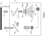
- the lidar 3 of the aforementioned document comprises the LAS laser source temporally modulated by the aforementioned periodic ramp of excursion B and duration T, and the coherence length of the laser radiation is at least twice greater than the maximum predetermined distance zmax between the scene to observe Sc and lidar 3.
- the lidar 3 also includes an optical device DS, called a separator corresponding to the aforementioned first optical device DO1.
- the second optical device DO2 comprises an optical recombination device DR adapted to spatially superimpose the reference beam Lref on the beam reflected by the scene Lo,r, so as to form the recombined beam.
- the second optical device DO2 also comprises an optical imaging system Im with optical axis AO (diaphragm Diaph) which produces an image of the scene by imaging the beam reflected by the scene Lo,r on the detector 41.
- the scene typically being at a distance much greater than the focal length of the optic Im, the detector 41 is placed substantially in the focal plane of the optic Im.
- the optical devices DO1 and DO2 are configured so that each pixel Pij of the detector receives a portion of the image beam coming from the scene called Lo,r/pix and a portion of the reference beam called Lref/pix, and that the portions are superimposed spatially on each pixel.
- these devices are configured, for example with the addition of additional optics Si (not shown), to transport the reference beam from the laser source to an intermediate image plane PI, perpendicular to the optical axis AO of the optical imaging system Im, so as to produce a coherent reference source (virtual or real) with the reflected beam.
- the intermediate plane PI is located close to the optical imaging system, so as to generate flat tint fringes, obtained by interference between the portion of the reflected beam detected Lo,r/pix and the portion of the detected reference beam Lref/pix, on each illuminated pixel Pij.
- This flat tint condition implies that, on each pixel Pij, an axis of propagation of the portion Lo,r/pix of the reflected beam is collinear or substantially collinear with an axis of propagation of the portion Lref/pix of the reference beam.
- a virtual or real intermediate image PS of the reference beam is formed in the intermediate image plane PI, the plane PI being arranged so as to generate flat tint fringes, obtained by interference between the portions, on each illuminated pixel.
- the coherent lidar imaging system 3 further comprising at least one electronic processing circuit configured to calculate, for each pixel Pij, a frequency F(i,j) of the beat of the portion of the image beam with the portion of the reference beam illuminating the pixel.
- the lidar 3 comprises a processing unit UT connected to the laser source and to the detector 41, and configured to determine a distance of points of the scene imaged on the pixels, from the beat frequency calculated and associated with each pixel and from the modulated optical frequency of the laser radiation.
- the processing circuit can be located in each pixel, along a row or a column, or in the processing unit UT.
- lidar 3 integrating a matrix detector is compatible with a large number of pixels (no scanning) making it possible to produce a high-resolution lidar image. Heterodyne mixing takes place here in each pixel.
- B and T are constant.
- the frequency f R must be able to be measured over the entire extent of the range ⁇ f R going from f Rmin defined by zmin to f Rmax defined by zmax.
- ⁇ f R increases, which involves increasing the bandwidth of the amplification circuit(s) of i PD , which increases the noise and consumption of these circuits. This also increases the photon noise of the DC component of i PD and decreases the signal-to-noise ratio. Indeed, in a known manner, the signal-to-noise ratio is inversely proportional to ⁇ f R . A decrease in signal-to-noise ratio can lead to poor counting due to noise.
- An aim of the present invention is to remedy the aforementioned drawbacks by proposing a coherent lidar imaging system allowing a reduction in the detection electronics necessary for measuring the frequency of the heterodyne signal and an improvement in the signal to noise ratio.
- the coherent lidar system further comprises a scanning device configured to illuminate point by point or line by line the scene with the object beam.
- the laser source and/or the first optical device are configured to illuminate the entire scene
- the detector comprises a plurality of pixels distributed in a matrix
- the second optical device is configured to superimpose, at the level of the photo-detector of each pixel, the reference beam and the beam reflected by the scene in a substantially identical direction of propagation.
- the frequency shift device comprises at least one acousto-optic modulator (AOM) operating in order -1.
- AOM acousto-optic modulator
- a modulation on the frequency range i is called subphase i
- step A the optical frequency of the laser radiation generated is not modulated for a duration T0 prior to the durations Ti
- step E detects a so-called reference signal during the duration T0
- step F comprises a comparison sub-step in which, for each sub-phase, the integrated reference signal and the detected signal integrated during said sub-phase are compared. phase.
- the document FR 2207829 (not published on the date of filing of this application) proposes to improve the signal-to-noise ratio while retaining the same dynamic z min -z max , by reducing the bandwidth ⁇ f R.
- each capture interval or sub-phase Ci corresponds to the supply of a beam having its optical frequency f modulated continuously and linearly over a frequency range of width Bi during the duration Ti of this sub-phase. Furthermore, it is expected that each sub-phase Ci corresponds to a Bi/Ti ratio different from that of the Bi/Ti ratios of the N-1 other sub-phases.
- Each sub-phase Ci (Bi, Ti) then corresponds to a bandwidth ⁇ f Ri reduced compared to ⁇ f R and makes it possible to detect distances z included in a range ⁇ zi going from z mini to z maxi with z mini ⁇ z maxi .
- a lidar with such frequency modulation is called a “multichirp lidar”.
- the Bi/Ti ratios are determined so that for i ranging from 1 to N-1 z mini+1 is substantially equal to z maxi without being strictly greater than zmax i .
- Ki z max i z min i
- Ki K, K real number strictly greater than 1.
- the Ki values of at least two sub-phases are different.
- f Rmini of the same value for each sub-phase Ci, called f Rmax
- f Rmax of the same value for each sub-phase Ci
- f Rmin f Rmin
- the determination of z is carried out by noting the instant for which the pixel measures a frequency included in the interval [f Rmin , f Rmax ]. This instant is located in only one of the sub-phases. Knowing the Bi and Ti of this subphase, we determine z.
- the frequency of the laser beam is modulated from the same frequency fstart, which implies that at the end of each sub-phase the frequency must be instantly returned to the frequency fstart. This requests the response of the laser source and its CCL control circuit.
- a second way of flattening the heterodyne signal is to work on the optical frequency of the beam Lref.
- the signal Lref of shifted frequency f opt-LOd interfering with the signal of the scene of frequency f opt-sc produces a constant heterodyne signal with a zero beat frequency which is detected on the imager with more simplified electronics.
- the figures 5 and 6 explain the difference between adding a time delay and shifting the optical frequency of Lref. Both solutions produce a heterodyne signal with zero beat frequency.
- the signal beat frequency fs is determined from the signal detected Spix by the photodetector.
- the concept of shifting applied to a monochirp lidar with parameter (B, T) consists of shifting (reducing) the frequency of the wave coming from the laser f opt-l (“classic” reference frequency) by a frequency fd varying in the interval [f Rmin ;f Rmax ], so that the difference between the reference frequency and the shifted reference frequency covers a set of frequencies including the frequency f R to be measured.
- the frequency f opt-LOd is thus between [f opt-l -f Rmax ; f opt-l - f Rmin ].
- an offset frequency fd varying in the interval [f Rmin ; f Rmax ] the beat frequency signal fs is canceled or minimized at a given “instant” (in fact a time range to be able to measure a frequency).
- the distance information z is then encoded in the particular fd value fda corresponding to this “instant”, such as: fda
- 2 Bz cT .
- the lidar according to the invention is a multichirp lidar for which the aforementioned offset concept is applied, in order to improve its performance.
- ⁇ z i changes according to the phases, and therefore the resolution as well. This is not a problem, in practice we will have a distance resolution which degrades with the distance in absolute value, but this is generally acceptable. For example: resolution of 1mm at 1m, and 1cm at 10m.
- a single offset frequency fd0 chosen in the interval [f Rmin ;f Rmax ] makes it possible to cancel the beat frequency fs for a sub phase Ci associated with the distance interval [z min ; z max ] included in the distance excursion of the desired lidar [z min ; z max ].
- Ci fs goes to zero for the distances included in z mini and z maxi of said sub-phase.
- the frequencies f Rmin and f Rmax are respectively the minimum and maximum heterodyne beat signal frequencies in the multichirp case in the absence of a frequency shift device (corresponding to zmin and zmax).
- FIG. 8 An example of the applied frequency offset fd0 is shown figure 8 for modulation of the laser source as illustrated in the figure 4 .
- the moment at which the beat frequency becomes zero or minimized the moment is in fact a time range to be able to measure a frequency.
- the continuous level of the measured signal is different from the continuous level of the signal without modulation (ambient signal), because it is added to the latter (see below).
- the offset frequency fd0 is chosen between f Rmax and f Rmin .
- FIG. 9 illustrates a coherent lidar system 10 according to the invention. It comprises a laser source SL configured to generate laser radiation L with a laser optical frequency f opt-l varying linearly over a plurality of N successive frequency ranges indexed i, with N greater than or equal to 2.
- a frequency range having a width Bi and a duration Ti, a sum of all said frequency ranges corresponding to an overall duration T, an absolute value of a ratio Bi/Ti being different for each frequency range, as described previously.
- the lidar 10 also comprises a first optical device D1 configured to spatially separate the laser radiation L into a reference beam Lref and an object beam Lo directed towards the scene to be observed Sc, a detection device Det comprising at least one pixel P comprising a PD photo-detector component.
- the lidar 10 also comprises a second optical device D2 configured to simultaneously provide said pixel with a recombined beam Lrecomb corresponding to a superposition of the reference beam Lref and a beam reflected by the scene Lo,r when it is illuminated by the object beam .
- the lidar 10 also includes a frequency shift device FSD arranged in the path of the reference beam and configured to shift the laser optical frequency by an offset frequency fd0 included in the interval [f Rmin , f Rmax ].
- FSD frequency shift device
- the lidar 10 also includes a processing unit UT configured to control the laser source (via its control circuit CCL) and which is connected to the detection device Det.
- the coherent lidar system 10 is further configured to determine distance information from a signal detected Spix by the pixel P.
- the distance information z associated with P is determined from the values Bi 0 and Ti 0 of the laser optical frequency range applied at the moment when the beat frequency fs of the detected signal is canceled or minimized, as explained previously.
- the processing unit UT connected to the control circuit of the laser source CCL, allows the identification of the frequency range of parameters (Bi 0 , Ti 0 ), once the cancellation moment of fs determined by the circuit reading CL.
- the coherent system according to the invention further comprising a scanning device SD configured to illuminate the scene with the object beam point by point (first embodiment).
- the SD device illuminates the scene line by line.
- each point of the scene should be illuminated for a duration at least equal to T (so that identification of zero/minimum fs is possible) and the detector comprises a single pixel.
- the detector comprises an array of pixels.
- the coherent lidar system 10 has an architecture as described in the document WO2021144357 and remembered Figure 3 .
- the laser source and/or the first optical device D1 are configured to illuminate the entire scene, and the detector comprises a plurality of pixels Pij distributed in a matrix.
- the second optical device D2 is configured to superimpose, at the level of the photo-detector PDij of each pixel, the reference beam Lref/pix and the beam reflected by the scene Lo,r/pix in a substantially identical direction of propagation.
- the device D2 typically comprises for this purpose an optical recombination device DR and an optical imaging system Im as described previously.
- the frequency shift device FSD placed on the path of the reference beam is an AOM acousto-optic modulator illustrated Figure 12 .
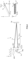
- An acousto-optic modulator is based on the principle of the photo-elastic effect.
- An acoustic wave of frequency f RF propagates in a material which slightly disturbs the optical parameters of this material and creates a network of steps A, wavelength of the acoustic wave.
- the incident optical beam is deflected by the grating (diffraction) proportionally to the frequency of the acoustic wave which propagates in the material.
- the optical frequency of the deflected beam is shifted by the value of the frequency of the acoustic wave f RF .
- ⁇ opt the wavelength of the optical beam
- A the wavelength the acoustic wave
- ⁇ B the Bragg angle of incidence of the optical beam.
- V speed of the acoustic wave in the material V speed of the acoustic wave in the material.
- the diffraction angle varies according to ⁇ and the frequency of the optical wave is also modulated. This property is not used here.
- the frequency shift device comprises two or more acousto-optic modulators, operating on orders -1 or +1 depending on the desired shift frequency.
- An optical acousto deflector can also be used in silicon photonics. Other types of frequency shifting devices may also be used.
- an electro-optical “phase-shifter” (device that shifts the phase) is driven by a sawtooth signal with a peak-to-peak driving amplitude that leads to exactly a 2 ⁇ phase shift of the optical carrier. This results in a phase shift which is piecewise linear in time and therefore leads to a frequency shift which corresponds to the fundamental frequency of the sawtooth control signal. It is also possible to use thermo-optical “phase-shifters” instead of electro-optical “phase-shifters”.
- Mach-Zehnder modulators In the case of SSB modulation, two Mach-Zehnder modulators are combined with a phase shift of ⁇ /2 to form an optical IQ modulator.
- the in-phase (I) and quadrature (Q) Mach-Zehnder modulators are respectively driven with a sine signal and a cosine signal, which, in the small-signal regime, leads to a frequency shift which corresponds to the frequency of the sinusoidal control signals.
- the processing to determine the moment for which the beat frequency fs of the detected signal Spix is minimum or zero is preferably carried out, at least in part, at the pixel level in a dedicated reading circuit CL.
- the pixel P comprises a photodetector PD configured to generate an electrical signal Spix, typically from the heterodyne photocurrent i PD (see figure 2 ), whose amplitude depends on the intensity of the optical beam detected.
- the dedicated reading circuit CL is coupled to the photodetector PD which delivers a Spix signal.
- a reference signal REF which corresponds to the signal coming from the scene without modulation of the optical frequency is detected before the Spix signal.
- the optical frequency of the laser radiation generated is not modulated for a duration T0 prior to the durations Ti, as illustrated Figure 13 .
- the non-modulation of the laser beam for a duration T0 just before the application of the modulations during the sub-phases Ci, is called the calibration phase.
- the signal detected by the photodetector during this duration T0 is called reference signal REF.
- ⁇ is the phase shift between the two channels, which can be anywhere between 0 and 2 ⁇ , so the additional DC component compared to the previous case can be positive, negative or zero.
- the detection of the instant for which for a pixel the detected signal Spix is continuous is thus carried out using the signal REF, in the manner illustrated Figure 14 , by detecting a “delta” as defined above.
- An INTEG integrator integrates the signals REF and SIG, respectively called REF' and SIG' for each sub-period Ti (sub-phase Ci).
- the current sub-phase Ci during integration is identified by the circuit CL, that is to say that the current values (Bi, Ti) are memorized.
- This pixel is assigned the value of z calculated with the current values (Bi, Ti), and this value is stored in a memory. Once the pixel is read, it is disabled for the rest of the frame. In this way, at each sub-period Ti, all the pixels which are at this same distance are read and deactivated. At the end of the multi-chirp signal, a depth image is available across the entire array. We can thus obtain a depth map at video frame rate.
- This architecture makes it possible to generate scene distance histograms in real time. By counting the number of pixels at each distance value in a memory, we obtain the distribution of depth values from the scene. This can be useful for adjusting and optimizing the multichirp signal to target the range of distances to be detected.
- the circuit CL thus comprises an integrator INTEG which integrates REF and Spix, the result of which is the integrated signal REF' and Spix', a comparator COMP which switches to the high state when Sipx'>REF' and a CLOG logic block which provides the address (Xadd, Yadd) of the pixel in question when the comparator is in the high state.
- the invention relates to a method for acquiring a distance z of a coherent lidar system 10 to a scene.
- laser radiation L is generated with a laser optical frequency f opt-l varying linearly over a plurality of N successive frequency ranges indexed i as described previously.
- the laser radiation L is spatially separated into a reference beam Lref and an object beam Lo directed towards a scene to be observed (Sc) and the scene is illuminated with the object beam.
- the laser optical frequency of the reference beam is shifted by an offset frequency fd0 included in the interval [f Rmax , f Rmin ], with f Rmax and f Rmin corresponding respectively to an associated beat heterodyne frequency at a maximum measurement distance zmax and at a minimum measurement distance zmin in the absence of the offset of the laser optical frequency of the reference beam.
- a moment is determined from the detected signal at which the beat frequency fs of the detected signal is canceled or minimized. Then we determine values Bi 0 and Ti 0 of the range of the laser optical frequency applied to said moment and finally distance information z is determined from the values Bi 0 and Ti 0 .
- step A the optical frequency of the laser radiation generated is not modulated for a duration T0 prior to the durations Ti (calibration phase).
- step E a so-called reference signal REF is detected during the duration T0 which is stored.
- step F comprises a comparison sub-step in which, for each sub-phase, the integrated reference signal REF' and the integrated detected signal Spix' are compared during said sub-phase.
Landscapes
- Engineering & Computer Science (AREA)
- Physics & Mathematics (AREA)
- Computer Networks & Wireless Communication (AREA)
- General Physics & Mathematics (AREA)
- Radar, Positioning & Navigation (AREA)
- Remote Sensing (AREA)
- Electromagnetism (AREA)
- Optical Radar Systems And Details Thereof (AREA)
Applications Claiming Priority (1)
| Application Number | Priority Date | Filing Date | Title |
|---|---|---|---|
| FR2214276A FR3144307B1 (fr) | 2022-12-22 | 2022-12-22 | Lidar cohérent à modulation de fréquence à traitement amélioré |
Publications (1)
| Publication Number | Publication Date |
|---|---|
| EP4390449A1 true EP4390449A1 (de) | 2024-06-26 |
Family
ID=85936972
Family Applications (1)
| Application Number | Title | Priority Date | Filing Date |
|---|---|---|---|
| EP23219454.8A Pending EP4390449A1 (de) | 2022-12-22 | 2023-12-21 | Kohärenter fm-lidar mit verbesserter verarbeitung |
Country Status (4)
| Country | Link |
|---|---|
| US (1) | US20240210537A1 (de) |
| EP (1) | EP4390449A1 (de) |
| CN (1) | CN118244292A (de) |
| FR (1) | FR3144307B1 (de) |
Citations (5)
| Publication number | Priority date | Publication date | Assignee | Title |
|---|---|---|---|---|
| FR2207829A1 (de) | 1972-11-29 | 1974-06-21 | Salvade Daniel | |
| US20060227316A1 (en) * | 2005-04-06 | 2006-10-12 | Phillip Gatt | Three-dimensional imaging device |
| US7986397B1 (en) * | 2008-04-30 | 2011-07-26 | Lockheed Martin Coherent Technologies, Inc. | FMCW 3-D LADAR imaging systems and methods with reduced Doppler sensitivity |
| US20200200903A1 (en) * | 2018-12-20 | 2020-06-25 | Gm Cruise Holdings Llc | Lidar system that is configured to compute ranges with differing range resolutions |
| WO2021144357A1 (fr) | 2020-01-16 | 2021-07-22 | Commissariat à l'Energie Atomique et aux Energies Alternatives | Systeme d'imagerie lidar cohérent |
-
2022
- 2022-12-22 FR FR2214276A patent/FR3144307B1/fr active Active
-
2023
- 2023-12-20 US US18/391,336 patent/US20240210537A1/en active Pending
- 2023-12-21 EP EP23219454.8A patent/EP4390449A1/de active Pending
- 2023-12-22 CN CN202311780650.8A patent/CN118244292A/zh active Pending
Patent Citations (5)
| Publication number | Priority date | Publication date | Assignee | Title |
|---|---|---|---|---|
| FR2207829A1 (de) | 1972-11-29 | 1974-06-21 | Salvade Daniel | |
| US20060227316A1 (en) * | 2005-04-06 | 2006-10-12 | Phillip Gatt | Three-dimensional imaging device |
| US7986397B1 (en) * | 2008-04-30 | 2011-07-26 | Lockheed Martin Coherent Technologies, Inc. | FMCW 3-D LADAR imaging systems and methods with reduced Doppler sensitivity |
| US20200200903A1 (en) * | 2018-12-20 | 2020-06-25 | Gm Cruise Holdings Llc | Lidar system that is configured to compute ranges with differing range resolutions |
| WO2021144357A1 (fr) | 2020-01-16 | 2021-07-22 | Commissariat à l'Energie Atomique et aux Energies Alternatives | Systeme d'imagerie lidar cohérent |
Also Published As
| Publication number | Publication date |
|---|---|
| CN118244292A (zh) | 2024-06-25 |
| US20240210537A1 (en) | 2024-06-27 |
| FR3144307A1 (fr) | 2024-06-28 |
| FR3144307B1 (fr) | 2024-12-13 |
Similar Documents
| Publication | Publication Date | Title |
|---|---|---|
| EP3504559B1 (de) | Verfahren zur verarbeitung eines signals aus kohärentem lidar und zugehöriges lidar-system | |
| EP0870180B1 (de) | Optisches bauelement zur polarisationsmodulation, und dessen verwendung in einem polarimeter oder ellipsometer | |
| EP0173617B1 (de) | Sender-Empfängersysteme für Laserbilderzeugung | |
| EP3563178B1 (de) | Verfahren zur verarbeitung eines signals aus einem kohärenten lidar zur geräuschreduktion und zugehöriges lidar-system | |
| EP3019822B1 (de) | Optische vorrichtung zur messung eines physikalischen parameters und zugehöriges verfahren | |
| EP4256291B1 (de) | Vorrichtung zur breitbandigen spektralanalyse eines signals | |
| EP3243042A1 (de) | Faseroptischer sensor | |
| FR2645264A1 (fr) | Gyroscope a fibre optique | |
| EP2920652B1 (de) | Ausseraxiale digitale heterodyne holografie | |
| WO2012038662A1 (fr) | Mesure telemetrique utilisant un dispositif de type lidar a detection heterodyne | |
| EP4004597B1 (de) | Verfahren für kohärente lidar-bildgebung und zugehöriger lidar | |
| EP4390449A1 (de) | Kohärenter fm-lidar mit verbesserter verarbeitung | |
| EP3044697B1 (de) | Elektronisches verfahren zur extraktion der amplitude und der phase eines signals in einer synchronen detektion und interferometrische anordnung zur durchführung des verfahrens | |
| FR2532417A1 (fr) | Disposition interferometrique pour la mesure de distances opto-electriques | |
| EP4078217B1 (de) | Lidar-system mit zwei diffraktiven komponenten | |
| FR3118197A1 (fr) | Lidar cohérent à modulation de fréquence amélioré | |
| FR2677456A1 (fr) | Systeme laser a detection heterodyne avec reduction des effets de la lumiere parasite. | |
| EP3977158B1 (de) | Lidar-system mit einem interferenziellen diffraktiven element und lidar-abbildungsverfahren | |
| EP0635730A1 (de) | Geschwindigkeitsmesser mit dynamischen Hologramm | |
| EP0450244B1 (de) | Detektionsvorrichtung mit optischen Fibern | |
| WO1997024630A1 (fr) | Systeme optique de mesure de vitesse et/ou de distance d'objet |
Legal Events
| Date | Code | Title | Description |
|---|---|---|---|
| PUAI | Public reference made under article 153(3) epc to a published international application that has entered the european phase |
Free format text: ORIGINAL CODE: 0009012 |
|
| STAA | Information on the status of an ep patent application or granted ep patent |
Free format text: STATUS: REQUEST FOR EXAMINATION WAS MADE |
|
| 17P | Request for examination filed |
Effective date: 20231221 |
|
| AK | Designated contracting states |
Kind code of ref document: A1 Designated state(s): AL AT BE BG CH CY CZ DE DK EE ES FI FR GB GR HR HU IE IS IT LI LT LU LV MC ME MK MT NL NO PL PT RO RS SE SI SK SM TR |
|
| RAP3 | Party data changed (applicant data changed or rights of an application transferred) |
Owner name: COMMISSARIAT A L'ENERGIE ATOMIQUE ET AUX ENERGIESALTERNATIVES |