EP2921079B1 - Meubles destiné à s'asseoir ou s'allonger dotée d'une pièce rapportée - Google Patents
Meubles destiné à s'asseoir ou s'allonger dotée d'une pièce rapportée Download PDFInfo
- Publication number
- EP2921079B1 EP2921079B1 EP15155573.7A EP15155573A EP2921079B1 EP 2921079 B1 EP2921079 B1 EP 2921079B1 EP 15155573 A EP15155573 A EP 15155573A EP 2921079 B1 EP2921079 B1 EP 2921079B1
- Authority
- EP
- European Patent Office
- Prior art keywords
- connection
- seating
- frame
- attachment
- reclining furniture
- Prior art date
- Legal status (The legal status is an assumption and is not a legal conclusion. Google has not performed a legal analysis and makes no representation as to the accuracy of the status listed.)
- Active
Links
- 229920003023 plastic Polymers 0.000 claims description 5
- 239000004033 plastic Substances 0.000 claims description 5
- 239000002184 metal Substances 0.000 claims description 2
- 230000000903 blocking effect Effects 0.000 claims 1
- 239000000463 material Substances 0.000 claims 1
- 238000003780 insertion Methods 0.000 description 7
- 230000037431 insertion Effects 0.000 description 7
- 238000009434 installation Methods 0.000 description 3
- 238000004519 manufacturing process Methods 0.000 description 3
- 229910000831 Steel Inorganic materials 0.000 description 2
- 239000010959 steel Substances 0.000 description 2
- 150000001875 compounds Chemical class 0.000 description 1
- 238000006073 displacement reaction Methods 0.000 description 1
- 230000000694 effects Effects 0.000 description 1
- 230000005484 gravity Effects 0.000 description 1
- 230000002093 peripheral effect Effects 0.000 description 1
Images


Classifications
-
- A—HUMAN NECESSITIES
- A47—FURNITURE; DOMESTIC ARTICLES OR APPLIANCES; COFFEE MILLS; SPICE MILLS; SUCTION CLEANERS IN GENERAL
- A47C—CHAIRS; SOFAS; BEDS
- A47C7/00—Parts, details, or accessories of chairs or stools
- A47C7/54—Supports for the arms
- A47C7/546—Supports for the arms of detachable type
-
- A—HUMAN NECESSITIES
- A47—FURNITURE; DOMESTIC ARTICLES OR APPLIANCES; COFFEE MILLS; SPICE MILLS; SUCTION CLEANERS IN GENERAL
- A47C—CHAIRS; SOFAS; BEDS
- A47C7/00—Parts, details, or accessories of chairs or stools
- A47C7/36—Supports for the head or the back
- A47C7/40—Supports for the head or the back for the back
- A47C7/42—Supports for the head or the back for the back of detachable or loose type
Definitions
- the invention relates to a seat and / or reclining furniture, in particular armchair, sofa, couch or bed, with a frame and at least one attachment, wherein the attachment is connected via at least one mounting unit comprising at least two separate connections to the frame, wherein the first connection is a plug connection, wherein the attachment is held pivotally in the inserted state relative to the frame.
- Seating furniture and reclining furniture are usually made from a number of prefabricated components to reduce manufacturing costs.
- the seating and reclining furniture typically have a structuring and contributing to the strength of the frame on which other components, so-called attachments are mounted.
- As a frame both very simply designed frame and functional fittings and swivel fittings come into question when the seating or reclining furniture between different positions is adjustable to offer the user of the chair several comfortable positions.
- the seating or the reclining furniture can be a chair, a sofa, a couch or a bed.
- attachments are, for example, a backrest, a seat, a footboard, an armrest or a side panel in question.
- Each of these attachments can be made adjustable if necessary, either separately or together with at least one additional attachment.
- a chair of the type mentioned is from the DE 44 40 553 C1 known. Another seating is for example from the DE 101 17 820 A1 known.
- the backrest can be plugged in the assembly of the chair in a frame.
- two backs are made on each side of the backrest separate connections between the backrest and the frame closed.
- the frame on each side of the backrest has two slots in the roles of the backrest can be introduced. The roles are introduced one after the other. First, a roller is inserted into a corresponding slot on each side and the backrest then pivoted so far, until the other two rollers get into engagement with the remaining slots.
- the first connection between the attachment and the frame is first produced during assembly of the chair and / or reclining furniture.
- This connection is also a plug connection.
- Such a connection can be produced easily, quickly and inexpensively. It is preferred if a section of the attachment provided for this purpose is inserted into a section of the frame designed for this, in order to simplify the mounting of the attachment. Alternatively or additionally, however, the opposite is also conceivable.
- the attachment and the frame are at least partially aligned with each other, which simplifies the further assembly of the attachment.
- the first connection is configured to allow pivoting to close the second connection. Further preferably, a defined abutment of the attachment is provided on the frame by the first connection, so that a defined pivoting of the first connection can be ensured.
- the first connection is therefore designed in particular form-fitting manner.
- the second connection By pivoting the first connection, so in particular a pivoting of the attachment relative to the frame around the first connection around, then the second connection can be closed.
- the first connection can provide a pivot axis for this purpose and also serve to guide the attachment for producing the second connection.
- the first connection may be formed such that the second connection forcibly finds itself in the right direction when pivoting the first connection.
- the second connection can thus be aligned by the first connection in a suitable manner, so that the second connection can be closed easily.
- the second connection is designed as a latching connection and therefore has a latching nose and an undercut.
- the detent engages behind the undercut and thus prevents accidental disconnection of the second connection by means of a corresponding positive connection.
- the locking of the second connection is brought about by the pivoting of the first connection.
- the first connection is pivoted so far that the detent latches behind the undercut. After the locking lug is engaged behind the undercut, the first connection is prevented from swinging back through the form-fit that forms thereby.
- the attachment and the frame are captively connected to each other after closing the first and the second connection.
- the forces that can be absorbed by the connections are so high that an accidental disconnection of Attachment and frame during normal operation of the chair and / or the reclining furniture is prevented.
- the plug connection of the first connection forms a positive connection in the inserted state in at least two mutually perpendicular directions.
- a defined positioning of the attachment relative to the frame can be provided, which allows a defined pivoting of the first connection.
- This is all the more true if in addition there is a positive connection in a further direction, which runs opposite to one of the other directions. It is particularly useful in this case if the positive connection exists in a plug-in direction.
- the insertion direction is given by the or a direction in which the attachment is inserted into the frame for closing the first connection or vice versa.
- the positive connection prevents further insertion and indicates to the fitter that the first connection has been established.
- the positive fit also exists in two directions, which are perpendicular to the direction of insertion and opposite to each other.
- the attachment can rest in at least two of these directions on the frame and / or vice versa.
- the attachment is a seat, a footboard, an armrest or a side panel of the chair and / or reclining furniture.
- the installation of these attachments can namely be preconfigured only conditionally.
- the installation of these attachments is relatively expensive.
- the at least one attachment can be fixed to a seat frame and / or a swivel fitting of the frame. This allows a high degree of flexibility with regard to the adjustability of the seat and / or reclining furniture.
- the attachment is connected via two mounting units with the frame.
- the two assembly units are preferably provided on opposite sides of the attachment and / or the frame.
- the first connection comprises a receptacle and a pin element received in a form-fitting manner in the receptacle.
- the recording can be designed for the sake of simplicity in the manner of a slot.
- the pin element may be formed as a kind of bolt.
- the pin element can also be designed differently.
- the pin element is more or less easily rotatable for pivoting the first connection, in particular in the receptacle, rotatably supported, preferably before the second connection is closed.
- the second connection preferably prevents the pivoting or rotation of the pin element, so that the attachment is held firmly on the frame.
- the recording is groove-shaped. This also facilitates, if necessary, the insertion of a pin element in the form of a spring element of the attachment and / or the frame in the groove-shaped receptacle.
- the receptacle may have a groove bottom, which prevents further insertion and indicates to the fitter that the first connection is in the inserted state.
- the receptacle can taper in the direction of the bottom or the groove bottom of the receptacle. Initially, therefore, an easy insertion is made possible without an excessively exact positioning must be carried out. In the area of the groove base, however, an exact forced positioning of the attachment and the frame can be achieved at the same time.
- a simple provision of the first connection can also be achieved in that the receptacle is formed by a hook portion of the frame or the attachment. This is particularly advantageous if the recording is provided on the attachment. Then, for simplicity, the pin member may be provided on the frame, wherein the hook portion may engage around the pin member. If the hook portion and / or the pin member provides a certain elasticity, the hook portion can engage in engaging around the pin member with this.
- the second connection forms a positive connection in the latched state at least in two mutually perpendicular directions.
- a positive connection can be formed by the latching between the locking lug and the undercut. It can then not only prevents pivoting back of the first connection, but also an accidental displacement of the attachment in at least one direction perpendicular thereto.
- the first connection and the second connection can form at least one positive connection in three mutually perpendicular spatial directions.
- the attachment can then be moved only limited in any direction in space, without any further movement would be blocked by a corresponding positive connection.
- the first connection or the second connection can have a positive connection in all three mutually perpendicular spatial directions. However, this is not absolutely necessary. But it can very well lead to a better locking of the attachment when the first connection and the second connection form a positive connection in at least one spatial direction. In this way, a double protection can be achieved and also higher forces can be absorbed.
- the at least one mounting unit can be a connecting element with the receptacle of the first connection and the Undercut the second connection.
- the receptacle and the undercut can thus be brought together in one component to reduce the design effort.
- the connecting element is formed in one piece. Even simpler and more compact it can be when the connecting element is integrally formed.
- the connecting element for the sake of simplicity as a flat product or flat profile, in particular a metallic flat product, such as a steel sheet may be formed.
- the connecting element can be accommodated in a receptacle of a further connecting unit.
- the further connection unit can then also be structurally simple and compact.
- the first connection unit and the second connection unit may together form the first connection and the second connection.
- a simple production of the further connection unit and a good connectability with the first connection unit can be achieved if the second connection unit is formed from plastic. Then, further preferably due to the elasticity of the plastic, the second connection unit have the latching lug, which simplifies the latching of the latching lug with the undercut.
- the latching lug of the second connection can be provided in such a way that when the first connection is closed the latching lug is displaced and / or pivoted against a restoring force from an initial position.
- the locking lug can therefore be provided so that the locking lug is forcibly deflected by approach of the attachment and the frame when inserting the attachment in the frame and / or vice versa. The thereby restoring force then ensures that the latch snaps without further action behind the undercut when the second connection is closed.
- the latching lug of the second connection is provided such that the latching lug when pivoting the first Moved connection for closing the second connection against a restoring force from an initial position and / or is pivoted.
- the locking lug can thus be provided so that by the mutual pivoting of the attachment and frame with closed first connection and / or in the inserted state of the first connection forcibly a deflection of the latch is effected, which leads to a bias.
- the corresponding restoring force then ensures that the locking lug snaps without further action behind the undercut when the first connection has been pivoted far enough, ie when the second connection is closed.
- the second connection can have at least two corresponding guide surfaces.
- the guide surfaces can in any case come in unsatisfactory alignment of attachment and frame in abutment against each other and slide when joining the second connection to each other, at least before the Schurasten the undercut by the latch.
- the guide surfaces are in particular coordinated so that the sliding of the guide surfaces together when joining the second connection leads to improved alignment of fixture and frame. Thus it can be ensured that the second connection can be easily joined even if initially inadequate alignment.
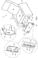
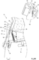
- a detail of a chair 1 in the form of a chair is shown schematically. Both the upholstery of the chair 1 and the backrest of the chair 1 has been neglected. Shown is in particular a frame 2, which gives the seating 1 structure and support, two side panels 3 and an attachment 4 in the form of a seat.
- the frame 2 is fixed on both sides to the side parts 3 and comprises a pivot fitting 5 for pivoting the chair 1, so that the user of the chair 1 can take several comfortable positions on the seating 1.
- the frame 2 comprises two lateral connecting elements 6 in the form of rails for mounting the attachment 4 in the form of the seat.
- the attachment 4 in turn comprises a peripheral frame 7, which can be mounted on the connecting elements 6.
- a mounting portion 8 is provided on both sides of the frame 2, which provides two connections 9,10.
- the first connection 9 is assigned to the rear side of the attachment 4 and the second connection 10 to the front side of the attachment 4 in the form of the seat.
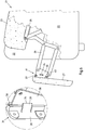
- the seating 1 is shown in a sectional view with a partially mounted attachment 4 with a pad 11.
- the first connection 9 is already closed, while the second connection 10 is still unconnected.
- the first connection 9 is formed by a plug connection comprising a pin element 12 and a hook section 13, wherein the hook section 13 can be plugged onto the pin element 12.
- the pin member 12 is inserted in the hook portion 13.
- the hook portion 13 has an opening which corresponds approximately to the vertical extent of the pin member 12 in the vertical direction.
- the first connection 9 is thus essentially free of play in this direction.
- Both upwards and downwards, the first connection 9 forms a positive connection between the pin element 12 and the hook section 13. However, this positive connection still allows pivoting of the first connection 9. This is when shown and so far preferred seating 1 the attachment 4 pivoted about the pin member 12. In this way, the front end of the attachment 4 can be pivoted downwards in the direction of the frame 2.
- the hook portion 13 forms a receptacle 14 in the form of a groove, wherein the pin member 12 rests positively on the groove base. In this way, an alignment of the attachment 4 is achieved in the horizontal direction. If the front end of the attachment part 4 is pivoted downward about the first connection 9, a latching lug 15 enters the corrsponding connection element 6 in the form of a rail. As a result, the locking lug 15 is pressed inwards and slides inside on the connecting element 6 until the latching lug 15 reaches the undercut 16 of the second connection 10 and then engages behind the undercut 16 of the second connection 10. Thus, the locking lug 15 engages positively behind the undercut 16 and the second connection 10 is closed, as shown in the Fig. 3 is shown.
- the first link 9 forms a positive connection in a vertical direction upward, in a vertical direction downward and in a horizontal direction forward.
- the terms horizontal and vertical are used herein, on condition that the seating 1 rises on a horizontal and level surface.
- the directions horizontally and vertically can therefore be regarded within certain limits as relative. However, this is sufficient to clearly distinguish the corresponding directions.
- the corresponding spatial directions are preferably perpendicular to each other.
- the connecting elements 18, 19 of the first connection 9 and the second connection 10 assigned to the attachment 4 are made of plastic.
- the frame 2 associated with the connecting elements 6 of the first and the second connection 9,10, however, are made of metal.
- the connecting elements 6 of the frame 2 need not be formed as continuous rails.
- the connecting elements 6 can also be provided in several parts and separately from each other.
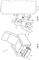
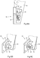
- a seat 21 is shown in the form of an armchair, the two side parts 22, a seat 23, a backrest 24 and a substantially disposed below the seat 23 frame 25 has.
- the frame 25 is fixed to the two side parts 22 and carries the seat 23 and the backrest 24.
- the frame 25 also includes a pivot fitting 26, on which another attachment 27 of the chair 21 in the form of a foot portion of a downwardly pivoted non-use position in a pivoted upward pivoted position of use.
- the attachment 27 is fixed on both sides of the attachment 27 on the pivot fitting 26 via two mounting units 28,29.
- the swivel fitting 26 and the frame 25 have a corresponding thereto Connecting elements 30, each of which together provide two connections 31,32.
- the connecting element 30 provided on the swivel fitting 26 is formed from a flat steel and has a receptacle 33 of a first connection 31 and an undercut 34 of a second connection 10.
- the receptacle 33 is groove-shaped.
- a hook portion 35 adjoins the receptacle 33.
- the groove-shaped receptacle 33 has, in the direction of the groove base, tapered groove flanks 36 or flanks of the receptacle 33 into which a spring element 37 of the corresponding connecting element 28, 29 of the attachment 27 can engage.
- the connecting element 28,29 of the attachment 27 is made of plastic and designed so that the connecting element 30 of the frame 25 is guided during the pivoting about the first connection 9 in the slot-shaped receptacle 38.
- the connecting element 30 of the frame 25 can be inserted in different ways into the receptacle 38 of the connecting element 28, 29 of the attachment 27. This can be done so that the connecting element 30 of the frame 25 already when inserting into the receptacle 38 of the attachment 30, the locking lug 39 urges aside.
- the connecting element 30 of the frame 25 can also only when pivoting about the first connection 31 against the detent 39 and push them to the side. In both cases acts on the locking lug 39, a restoring force, which ensures that the locking lug 39 the Undercut 34 engages behind when the connecting element 30 of the frame 25 has been completely pivoted into the receptacle 38 of the attachment 28,29.
- second connection 32 forms in addition to the latching connection and the positive connection to a withdrawal of the connecting element 30 of the frame 25 from the connecting element 28,29 of the attachment 27 still a positive connection in a direction perpendicular thereto.
- the connecting element 28, 29 of the attachment 27 has a stop 40 for the connecting element 30 of the frame 25.
- the abutment of the spring element 37 at the groove bottom of the receptacle 33 of the connecting element 30 of the frame 25 forms a positive connection.
- the attachment 27 facing edge 36 of the receptacle 33 of the connecting element 30 of the frame 25 with the recorded in the receptacle 33 spring member 37 forms a positive connection in a direction perpendicular thereto. Due to the substantially precise engagement of the connecting element 30 of the frame 25 in the connecting element 28,29 of the attachment 27 and a positive connection in the two transverse directions, that is in the direction of the side parts 22 of the chair 21, is provided.
- FIG. 7A-B Seating furniture 41 shown two attachment parts 27 are shown in the form of foot parts, which can be connected via the previously described connecting elements 28,29,30 with the frame 25. This is done in addition to the manner also described above, which is why this in connection with the embodiment according to Fig. 7A-B will not be explained again in detail.
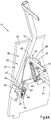
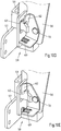
- a detail of a chair 51 is shown schematically.
- the upholstery has been omitted in this seating 51.
- only a part of the right rear side of the seat 51 is shown with a side part 52 and the connection of an attachment 53 in the form of a backrest to a frame 54 of the chair 51, which in the extent preferred seating 51 at the two side parts 52 is supported.
- the connection of the attachment 53 to the frame 54 of the seat 51 is a mounting unit 55, which is provided in the same manner on the side part, not shown.
- the mounting unit 55 comprises a connecting element 56 of the frame 54 and a connecting element 57 of the mounting part 53, which together provide a first connection 58 and a second connection 59.
- the first connection 58 is a plug connection, which is closed by attaching the connecting element 57 of the attachment 53 to the connecting element 56 of the frame 54.
- the connecting element 56 of the frame 54 has a groove-shaped receptacle 60 into which a pin element 61 of the connecting element 57 of the attachment 53 can be positively inserted in the form of a cross member, until the pin member 61 in abutment against a bottom of the receptacle 60 212. the groove bottom same.
- the attachment 53 In the inserted state there is a positive connection between the attachment 53 and the connecting element 56 and the frame 54 in a vertical direction down, a horizontal direction to the front and in a horizontal direction to the rear. Since both the groove bottom of the receptacle 60 and the receptacle 60 received in the pin member 61 are rounded, the attachment 53 can be pivoted about the first connection 58 to close the second connection 59, which is a snap-in connection ,
- the second connection 59 is shown in the closed state.
- the connecting element 56 of the frame 54 has a latching nose 62 which can engage behind an undercut 63 of the connecting element 57 of the attachment 53 when the attachment 53 is pivoted far enough back around the first connection 58.
- a pivoting back of the attachment 53 is prevented as a result of the positive engagement caused by the locking.
- the form-fitting acts, for example, in a horizontal direction to the rear.
- the engaging behind the undercut 63 by the latch 62 also leads to a positive connection in a direction vertically upwards.
- connecting elements 56, 57 of attachment 53 and frame 54 have abutment surfaces 64, 65 on, which bear against each other in the latched state of the second connection 59 and so ensure a positive connection in a horizontal direction forward.
- a positive connection in the horizontal direction to the left is achieved by the installation of the connecting elements 56, 57 in the region of the first connection 58.
- Analog is provided by the second mounting unit on the other side part a positive connection in the horizontal direction to the right. This is therefore unnecessary in the illustrated assembly unit 55.
- the connecting element 57 of the attachment 53 has an inclined guide surface 67 in the region of the second connection 59, which effects a forced alignment, while this on a corresponding guide surface 66 of the connecting element 56 of the frame 54 in the region of the second connection 59 is passed.
- the guide surfaces 66, 67 come into contact with one another and slide against one another.
- connection of the attachment 53 with the connecting element 56 or with the frame 54 can also be done by the attachment 53 and the pin member 61 is placed in the form of the cross member on the frame 54, approximately on the upper surface 68th Then, the attachment 53 are moved until the pin member 61 passes into the receptacle 60 of the frame 54 due to gravity. In this way, the first connection 58 is closed. Subsequently, the attachment 53 can be pivoted about the first connection 58 around. If necessary, the guide surfaces 66,67 come into abutment with each other to align the attachment 53. A further pivoting then automatically leads to a latching of the latching lug 62 and the undercut 63 of the second connection 59 in the form of a latching connection.
- the latching lug 62 is spring-loaded by the spring means 69.
- the latching lug 62 is engaged by the connecting element 57 of the attachment 53 when the second connection 59 is closed and thus lifted upwards, against the restoring force of the spring element 69.
- the locking lug 62 passes as a result of the restoring force of the spring means 69 in the undercut 63 of the connecting element 57 of the attachment 53.
- FIG. 10A-E Alternative embodiments of the second connection 59 in the form of a latching connection between the attachment 53 and the frame 54 are shown. For simplicity, the same reference numerals are used for the same components.
- the locking connection according to Fig. 10A the locking lug 62 is deflected on the connecting element 56 of the frame 54 by the designedg facedde connecting element 57 of the attachment 53 against the restoring force of a spring member 69 down.
- the undercut 63 of the connecting element 57 is above the latching lug 62 in the form of a pin or bolt, the latching lug 62 snaps into the undercut 63.
- the connecting element of the attachment could also be spring-loaded, so that the connecting element of the attachment and not the latch of the connecting element of the frame must be deflected.
- the detent may also be provided on the connecting element of the attachment and the undercut on the connecting element of the frame.
- a latching lug 62 is shown, which is held in a bolt 70. If the bolt 70 is guided through an opening 71 in the connecting element 56 of the frame 54, then the latching lug 62 can be pressed against the restoring force of a spring means 69 in the bolt 70. Behind the opening 71, the latching lug 69 is pushed out of the bolt 70 again as a result of the restoring force of the spring element 69, as a result of which the latching of the second connection 59 is achieved.
Landscapes
- Chairs For Special Purposes, Such As Reclining Chairs (AREA)
Claims (15)
- Meuble d'assise (1, 21, 41) et/ou d'allongement comprenant un bâti (2, 25) et au moins une partie rapportée (4, 27) sous la forme d'un siège, d'une partie de pied, d'un accoudoir ou d'une partie latérale disposée latéralement d'un dossier, la partie rapportée (4, 27) étant reliée au bâti (2, 25) par le biais d'au moins une unité de montage (28, 29) comprenant au moins deux liaisons (9, 10, 31, 32) séparées, la première liaison (9, 31) étant une liaison par enfichage, la deuxième liaison (10, 32) étant une liaison par enclipsage avec un tenon d'enclipsage (15, 39) et une contredépouille (16, 34) engagée par l'arrière par le tenon d'enclipsage (15, 39), et le tenon d'enclipsage (15, 39) et la contredépouille (16, 34) de la deuxième liaison (10, 32) pouvant être enclipsés par un pivotement de la première liaison (9, 31) dans l'état enfiché et, dans l'état enclipsé, bloquant un pivotement vers l'arrière de la première liaison (9,31),
caractérisé en ce que
la partie rapportée (4, 27) est maintenue pivotante par rapport au bâti (2, 25) dans l'état enfiché et en ce que la première liaison (9, 31) comporte un logement (14, 33) en forme de rainure et un élément formant broche (12, 37) qui est accueilli par complémentarité de formes dans le logement (14, 33). - Meuble d'assise et/ou d'allongement selon la revendication 1,
caractérisé en ce que
dans l'état enfiché, la première liaison (9, 31) forme une complémentarité de formes dans une direction d'enfichage et au moins une direction supplémentaire perpendiculaire à la direction d'enfichage. - Meuble d'assise et/ou d'allongement selon la revendication 1 ou 2,
caractérisé en ce que
la partie rapportée (4, 27, 53) est fixée à un cadre de siège et/ou un revêtement pivotant (5, 26) du bâti (2, 25, 54). - Meuble d'assise et/ou d'allongement selon l'une des revendications 1 à 3,
caractérisé en ce que
la partie rapportée (4, 27) est reliée au bâti (2, 25) par le biais de deux unités de montage (28, 29). - Meuble d'assise et/ou d'allongement selon l'une des revendications 1 à 4,
caractérisé en ce que
la première liaison (9, 31) comprend un logement (14, 33) allongé et un élément formant broche (12, 37) qui est accueilli par complémentarité de formes dans le logement (14, 33). - Meuble d'assise et/ou d'allongement selon la revendication 5,
caractérisé en ce que
le logement (14, 33) se rétrécit en direction du fond du logement (14, 33). - Meuble d'assise et/ou d'allongement selon la revendication 5 ou 6,
caractérisé en ce que
le logement (14, 33) est formé par une portion en crochet (13, 35) du bâti (2, 25) ou de la partie rapportée (4, 27). - Meuble d'assise et/ou d'allongement selon l'une des revendications 1 à 7,
caractérisé en ce que
dans l'état enclipsé, la deuxième liaison (10, 32) présente au moins une complémentarité de formes dans une direction perpendiculaire à la complémentarité de formes formée par l'enclipsage entre le tenon d'enclipsage (15, 39) et la contredépouille (16, 34). - Meuble d'assise et/ou d'allongement selon l'une des revendications 1 à 8,
caractérisé en ce que
la première et la deuxième liaison (9, 10, 31, 32) forment respectivement une complémentarité de formes dans trois directions spatiales qui sont perpendiculaires les unes aux autres. - Meuble d'assise et/ou d'allongement selon l'une des revendications 5 à 9,
caractérisé en ce que
l'au moins une unité de montage (28, 29) possède un élément de liaison (6, 18, 19, 28, 29, 30) comprenant le logement (14, 33) de la première liaison (9, 31) et la contredépouille (16, 34) de la deuxième liaison (10, 32). - Meuble d'assise et/ou d'allongement selon la revendication 10,
caractérisé en ce que
l'élément de liaison (30) est réalisé à partir d'un profil plat, de préférence métallique. - Meuble d'assise et/ou d'allongement selon la revendication 10 ou 11,
caractérisé en ce que
l'élément de liaison (30) est accueilli dans un logement (38) d'un élément de liaison supplémentaire (28, 29), de préférence constitué de matière plastique, et en ce que l'élément de liaison (30) et l'élément de liaison supplémentaire (28, 29) forment la première et la deuxième liaison (31, 32). - Meuble d'assise et/ou d'allongement selon l'une des revendications 1 à 12,
caractérisé en ce que
le tenon d'enclipsage (39) de la deuxième liaison (32) est conçu de telle sorte que lors de la fermeture de la première liaison (31), le tenon d'enclipsage (39) est décalé et/ou pivoté depuis une position initiale contre une force de rappel. - Meuble d'assise et/ou d'allongement selon l'une des revendications 1 à 13,
caractérisé en ce que
le tenon d'enclipsage (15, 39) de la deuxième liaison (10, 32) est conçu de telle sorte que lors du pivotement de la première liaison, le tenon d'enclipsage (15, 39) est décalé et/ou pivoté depuis une position initiale contre une force de rappel en vue de fermer la deuxième liaison (10, 32). - Meuble d'assise et/ou d'allongement selon l'une des revendications 1 à 14,
caractérisé en ce que
la deuxième liaison comporte au moins deux surfaces de guidage correspondantes destinées à glisser mutuellement l'une contre l'autre avant l'enclipsage de la deuxième liaison.
Applications Claiming Priority (1)
| Application Number | Priority Date | Filing Date | Title |
|---|---|---|---|
| DE102014002215.3A DE102014002215A1 (de) | 2014-02-20 | 2014-02-20 | Sitz- oder Liegemöbel mit Anbauteil |
Publications (2)
| Publication Number | Publication Date |
|---|---|
| EP2921079A1 EP2921079A1 (fr) | 2015-09-23 |
| EP2921079B1 true EP2921079B1 (fr) | 2019-04-03 |
Family
ID=52477666
Family Applications (1)
| Application Number | Title | Priority Date | Filing Date |
|---|---|---|---|
| EP15155573.7A Active EP2921079B1 (fr) | 2014-02-20 | 2015-02-18 | Meubles destiné à s'asseoir ou s'allonger dotée d'une pièce rapportée |
Country Status (2)
| Country | Link |
|---|---|
| EP (1) | EP2921079B1 (fr) |
| DE (1) | DE102014002215A1 (fr) |
Families Citing this family (3)
| Publication number | Priority date | Publication date | Assignee | Title |
|---|---|---|---|---|
| IT201800002948A1 (it) * | 2018-02-22 | 2019-08-22 | Lightson S R L Soc Benefit | Sedia con elementi intercambiabili |
| DE202019100107U1 (de) * | 2019-01-10 | 2020-04-16 | Innotec Motion GmbH | Sitzmöbelchassis |
| WO2022199181A1 (fr) * | 2021-03-22 | 2022-09-29 | 际诺思股份公司 | Ensemble de montage de meuble et meuble assemblé |
Family Cites Families (4)
| Publication number | Priority date | Publication date | Assignee | Title |
|---|---|---|---|---|
| DE4440553C1 (de) * | 1994-11-12 | 1996-03-14 | Sichelschmidt Stanzwerk | Anordnung zur Verbindung von zwei Elementen von Möbeln |
| DE20009339U1 (de) | 2000-05-24 | 2001-09-27 | Stanzwerk Wetter Sichelschmidt GmbH & Co. KG, 58300 Wetter | Sitzmöbel mit steckbefestigbarem Rückenteil |
| JP4740521B2 (ja) * | 2000-11-01 | 2011-08-03 | キャスケイド デザインズ インコーポレイテッド | 車椅子に特に適する調整可能の迅速な解放シートバックシステム |
| DE102013104033A1 (de) * | 2013-04-22 | 2014-10-23 | Ferdinand Lusch Gmbh & Co Kg | Sitzmöbel mit leicht zu montierender Rückenlehne |
-
2014
- 2014-02-20 DE DE102014002215.3A patent/DE102014002215A1/de not_active Ceased
-
2015
- 2015-02-18 EP EP15155573.7A patent/EP2921079B1/fr active Active
Non-Patent Citations (1)
| Title |
|---|
| None * |
Also Published As
| Publication number | Publication date |
|---|---|
| EP2921079A1 (fr) | 2015-09-23 |
| DE102014002215A1 (de) | 2015-08-20 |
Similar Documents
| Publication | Publication Date | Title |
|---|---|---|
| EP3516995B1 (fr) | Siège à appui-tête réglable en hauteur | |
| EP0236891A2 (fr) | Meuble pliant | |
| DE102014108359A1 (de) | Kindersitz, umwandelbar in mehrere Benutzungskonfigurationen | |
| DE112014000095T5 (de) | Vorrichtung zum Bewegen einer Kopfstütze | |
| DE8436612U1 (de) | Klappsessel | |
| EP4091502A1 (fr) | Support de dossier pour un siège | |
| EP2921079B1 (fr) | Meubles destiné à s'asseoir ou s'allonger dotée d'une pièce rapportée | |
| EP0743035B1 (fr) | Chaise, notamment chaise de bureau, avec un dossier réglable en hauteur | |
| DE29821875U1 (de) | Sessel mit Aufstehhilfe | |
| EP3031358B1 (fr) | Siege a module fonctionnel pivotant | |
| EP2796074B1 (fr) | Meuble rembourré | |
| EP2893843B1 (fr) | Siège doté d'un élément de tête pivotant motorisé | |
| EP3071845B1 (fr) | Vérin de levage et meuble pour s'asseoir et/ou s'étendre pourvu d'un vérin de levage | |
| DE102018126293B4 (de) | Lattenrost | |
| EP1915928A2 (fr) | Meubles, en particulier meubles destinés à s'asseoir | |
| EP1649786A1 (fr) | Ferrure pour l'articulation de supports des lattes d'un sommier | |
| DE102015117461B4 (de) | Stützsystem zum Einstellen einer Kopfstütze | |
| DE9311345U1 (de) | Stuhl | |
| EP3031359A1 (fr) | Siege a module fonctionnel pivotant | |
| EP2921082A1 (fr) | Meuble destiné à s'asseoir ou s'allonger doté d'un cadre et élément latéral y étant relié | |
| EP3850991B1 (fr) | Ferrure du repose-jambes | |
| DE29617255U1 (de) | Polstermöbelelement | |
| EP2389916A2 (fr) | Meuble de réglage dans une position d'aide à la mise en position debout | |
| DE102010055107B4 (de) | Möbelstück | |
| DE102014003516B4 (de) | Möbel mit verstellbarem Funktionsbauteil |
Legal Events
| Date | Code | Title | Description |
|---|---|---|---|
| PUAI | Public reference made under article 153(3) epc to a published international application that has entered the european phase |
Free format text: ORIGINAL CODE: 0009012 |
|
| AK | Designated contracting states |
Kind code of ref document: A1 Designated state(s): AL AT BE BG CH CY CZ DE DK EE ES FI FR GB GR HR HU IE IS IT LI LT LU LV MC MK MT NL NO PL PT RO RS SE SI SK SM TR |
|
| AX | Request for extension of the european patent |
Extension state: BA ME |
|
| 17P | Request for examination filed |
Effective date: 20160309 |
|
| RBV | Designated contracting states (corrected) |
Designated state(s): AL AT BE BG CH CY CZ DE DK EE ES FI FR GB GR HR HU IE IS IT LI LT LU LV MC MK MT NL NO PL PT RO RS SE SI SK SM TR |
|
| STAA | Information on the status of an ep patent application or granted ep patent |
Free format text: STATUS: EXAMINATION IS IN PROGRESS |
|
| 17Q | First examination report despatched |
Effective date: 20170206 |
|
| GRAP | Despatch of communication of intention to grant a patent |
Free format text: ORIGINAL CODE: EPIDOSNIGR1 |
|
| STAA | Information on the status of an ep patent application or granted ep patent |
Free format text: STATUS: GRANT OF PATENT IS INTENDED |
|
| INTG | Intention to grant announced |
Effective date: 20180606 |
|
| GRAJ | Information related to disapproval of communication of intention to grant by the applicant or resumption of examination proceedings by the epo deleted |
Free format text: ORIGINAL CODE: EPIDOSDIGR1 |
|
| STAA | Information on the status of an ep patent application or granted ep patent |
Free format text: STATUS: EXAMINATION IS IN PROGRESS |
|
| GRAP | Despatch of communication of intention to grant a patent |
Free format text: ORIGINAL CODE: EPIDOSNIGR1 |
|
| STAA | Information on the status of an ep patent application or granted ep patent |
Free format text: STATUS: GRANT OF PATENT IS INTENDED |
|
| INTC | Intention to grant announced (deleted) | ||
| INTG | Intention to grant announced |
Effective date: 20181005 |
|
| GRAS | Grant fee paid |
Free format text: ORIGINAL CODE: EPIDOSNIGR3 |
|
| GRAA | (expected) grant |
Free format text: ORIGINAL CODE: 0009210 |
|
| STAA | Information on the status of an ep patent application or granted ep patent |
Free format text: STATUS: THE PATENT HAS BEEN GRANTED |
|
| AK | Designated contracting states |
Kind code of ref document: B1 Designated state(s): AL AT BE BG CH CY CZ DE DK EE ES FI FR GB GR HR HU IE IS IT LI LT LU LV MC MK MT NL NO PL PT RO RS SE SI SK SM TR |
|
| REG | Reference to a national code |
Ref country code: GB Ref legal event code: FG4D Free format text: NOT ENGLISH |
|
| REG | Reference to a national code |
Ref country code: CH Ref legal event code: EP Ref country code: AT Ref legal event code: REF Ref document number: 1114679 Country of ref document: AT Kind code of ref document: T Effective date: 20190415 |
|
| REG | Reference to a national code |
Ref country code: DE Ref legal event code: R096 Ref document number: 502015008517 Country of ref document: DE |
|
| REG | Reference to a national code |
Ref country code: IE Ref legal event code: FG4D Free format text: LANGUAGE OF EP DOCUMENT: GERMAN |
|
| REG | Reference to a national code |
Ref country code: NL Ref legal event code: MP Effective date: 20190403 |
|
| REG | Reference to a national code |
Ref country code: LT Ref legal event code: MG4D |
|
| PG25 | Lapsed in a contracting state [announced via postgrant information from national office to epo] |
Ref country code: NL Free format text: LAPSE BECAUSE OF FAILURE TO SUBMIT A TRANSLATION OF THE DESCRIPTION OR TO PAY THE FEE WITHIN THE PRESCRIBED TIME-LIMIT Effective date: 20190403 |
|
| PG25 | Lapsed in a contracting state [announced via postgrant information from national office to epo] |
Ref country code: FI Free format text: LAPSE BECAUSE OF FAILURE TO SUBMIT A TRANSLATION OF THE DESCRIPTION OR TO PAY THE FEE WITHIN THE PRESCRIBED TIME-LIMIT Effective date: 20190403 Ref country code: CZ Free format text: LAPSE BECAUSE OF FAILURE TO SUBMIT A TRANSLATION OF THE DESCRIPTION OR TO PAY THE FEE WITHIN THE PRESCRIBED TIME-LIMIT Effective date: 20190403 Ref country code: SE Free format text: LAPSE BECAUSE OF FAILURE TO SUBMIT A TRANSLATION OF THE DESCRIPTION OR TO PAY THE FEE WITHIN THE PRESCRIBED TIME-LIMIT Effective date: 20190403 Ref country code: ES Free format text: LAPSE BECAUSE OF FAILURE TO SUBMIT A TRANSLATION OF THE DESCRIPTION OR TO PAY THE FEE WITHIN THE PRESCRIBED TIME-LIMIT Effective date: 20190403 Ref country code: PT Free format text: LAPSE BECAUSE OF FAILURE TO SUBMIT A TRANSLATION OF THE DESCRIPTION OR TO PAY THE FEE WITHIN THE PRESCRIBED TIME-LIMIT Effective date: 20190803 Ref country code: AL Free format text: LAPSE BECAUSE OF FAILURE TO SUBMIT A TRANSLATION OF THE DESCRIPTION OR TO PAY THE FEE WITHIN THE PRESCRIBED TIME-LIMIT Effective date: 20190403 Ref country code: LT Free format text: LAPSE BECAUSE OF FAILURE TO SUBMIT A TRANSLATION OF THE DESCRIPTION OR TO PAY THE FEE WITHIN THE PRESCRIBED TIME-LIMIT Effective date: 20190403 Ref country code: NO Free format text: LAPSE BECAUSE OF FAILURE TO SUBMIT A TRANSLATION OF THE DESCRIPTION OR TO PAY THE FEE WITHIN THE PRESCRIBED TIME-LIMIT Effective date: 20190703 Ref country code: HR Free format text: LAPSE BECAUSE OF FAILURE TO SUBMIT A TRANSLATION OF THE DESCRIPTION OR TO PAY THE FEE WITHIN THE PRESCRIBED TIME-LIMIT Effective date: 20190403 |
|
| PG25 | Lapsed in a contracting state [announced via postgrant information from national office to epo] |
Ref country code: BG Free format text: LAPSE BECAUSE OF FAILURE TO SUBMIT A TRANSLATION OF THE DESCRIPTION OR TO PAY THE FEE WITHIN THE PRESCRIBED TIME-LIMIT Effective date: 20190703 Ref country code: PL Free format text: LAPSE BECAUSE OF FAILURE TO SUBMIT A TRANSLATION OF THE DESCRIPTION OR TO PAY THE FEE WITHIN THE PRESCRIBED TIME-LIMIT Effective date: 20190403 Ref country code: LV Free format text: LAPSE BECAUSE OF FAILURE TO SUBMIT A TRANSLATION OF THE DESCRIPTION OR TO PAY THE FEE WITHIN THE PRESCRIBED TIME-LIMIT Effective date: 20190403 Ref country code: RS Free format text: LAPSE BECAUSE OF FAILURE TO SUBMIT A TRANSLATION OF THE DESCRIPTION OR TO PAY THE FEE WITHIN THE PRESCRIBED TIME-LIMIT Effective date: 20190403 |
|
| PG25 | Lapsed in a contracting state [announced via postgrant information from national office to epo] |
Ref country code: IS Free format text: LAPSE BECAUSE OF FAILURE TO SUBMIT A TRANSLATION OF THE DESCRIPTION OR TO PAY THE FEE WITHIN THE PRESCRIBED TIME-LIMIT Effective date: 20190803 |
|
| REG | Reference to a national code |
Ref country code: DE Ref legal event code: R097 Ref document number: 502015008517 Country of ref document: DE |
|
| PG25 | Lapsed in a contracting state [announced via postgrant information from national office to epo] |
Ref country code: RO Free format text: LAPSE BECAUSE OF FAILURE TO SUBMIT A TRANSLATION OF THE DESCRIPTION OR TO PAY THE FEE WITHIN THE PRESCRIBED TIME-LIMIT Effective date: 20190403 Ref country code: DK Free format text: LAPSE BECAUSE OF FAILURE TO SUBMIT A TRANSLATION OF THE DESCRIPTION OR TO PAY THE FEE WITHIN THE PRESCRIBED TIME-LIMIT Effective date: 20190403 Ref country code: EE Free format text: LAPSE BECAUSE OF FAILURE TO SUBMIT A TRANSLATION OF THE DESCRIPTION OR TO PAY THE FEE WITHIN THE PRESCRIBED TIME-LIMIT Effective date: 20190403 Ref country code: SK Free format text: LAPSE BECAUSE OF FAILURE TO SUBMIT A TRANSLATION OF THE DESCRIPTION OR TO PAY THE FEE WITHIN THE PRESCRIBED TIME-LIMIT Effective date: 20190403 |
|
| PLBE | No opposition filed within time limit |
Free format text: ORIGINAL CODE: 0009261 |
|
| STAA | Information on the status of an ep patent application or granted ep patent |
Free format text: STATUS: NO OPPOSITION FILED WITHIN TIME LIMIT |
|
| PG25 | Lapsed in a contracting state [announced via postgrant information from national office to epo] |
Ref country code: IT Free format text: LAPSE BECAUSE OF FAILURE TO SUBMIT A TRANSLATION OF THE DESCRIPTION OR TO PAY THE FEE WITHIN THE PRESCRIBED TIME-LIMIT Effective date: 20190403 Ref country code: SM Free format text: LAPSE BECAUSE OF FAILURE TO SUBMIT A TRANSLATION OF THE DESCRIPTION OR TO PAY THE FEE WITHIN THE PRESCRIBED TIME-LIMIT Effective date: 20190403 |
|
| 26N | No opposition filed |
Effective date: 20200106 |
|
| PG25 | Lapsed in a contracting state [announced via postgrant information from national office to epo] |
Ref country code: TR Free format text: LAPSE BECAUSE OF FAILURE TO SUBMIT A TRANSLATION OF THE DESCRIPTION OR TO PAY THE FEE WITHIN THE PRESCRIBED TIME-LIMIT Effective date: 20190403 |
|
| PG25 | Lapsed in a contracting state [announced via postgrant information from national office to epo] |
Ref country code: SI Free format text: LAPSE BECAUSE OF FAILURE TO SUBMIT A TRANSLATION OF THE DESCRIPTION OR TO PAY THE FEE WITHIN THE PRESCRIBED TIME-LIMIT Effective date: 20190403 |
|
| REG | Reference to a national code |
Ref country code: CH Ref legal event code: PL |
|
| GBPC | Gb: european patent ceased through non-payment of renewal fee |
Effective date: 20200218 |
|
| REG | Reference to a national code |
Ref country code: BE Ref legal event code: MM Effective date: 20200229 |
|
| PG25 | Lapsed in a contracting state [announced via postgrant information from national office to epo] |
Ref country code: LU Free format text: LAPSE BECAUSE OF NON-PAYMENT OF DUE FEES Effective date: 20200218 Ref country code: MC Free format text: LAPSE BECAUSE OF FAILURE TO SUBMIT A TRANSLATION OF THE DESCRIPTION OR TO PAY THE FEE WITHIN THE PRESCRIBED TIME-LIMIT Effective date: 20190403 |
|
| PG25 | Lapsed in a contracting state [announced via postgrant information from national office to epo] |
Ref country code: LI Free format text: LAPSE BECAUSE OF NON-PAYMENT OF DUE FEES Effective date: 20200229 Ref country code: CH Free format text: LAPSE BECAUSE OF NON-PAYMENT OF DUE FEES Effective date: 20200229 |
|
| PG25 | Lapsed in a contracting state [announced via postgrant information from national office to epo] |
Ref country code: GB Free format text: LAPSE BECAUSE OF NON-PAYMENT OF DUE FEES Effective date: 20200218 Ref country code: IE Free format text: LAPSE BECAUSE OF NON-PAYMENT OF DUE FEES Effective date: 20200218 Ref country code: FR Free format text: LAPSE BECAUSE OF NON-PAYMENT OF DUE FEES Effective date: 20200229 |
|
| PG25 | Lapsed in a contracting state [announced via postgrant information from national office to epo] |
Ref country code: BE Free format text: LAPSE BECAUSE OF NON-PAYMENT OF DUE FEES Effective date: 20200229 |
|
| REG | Reference to a national code |
Ref country code: AT Ref legal event code: MM01 Ref document number: 1114679 Country of ref document: AT Kind code of ref document: T Effective date: 20200218 |
|
| PG25 | Lapsed in a contracting state [announced via postgrant information from national office to epo] |
Ref country code: AT Free format text: LAPSE BECAUSE OF NON-PAYMENT OF DUE FEES Effective date: 20200218 |
|
| REG | Reference to a national code |
Ref country code: DE Ref legal event code: R082 Ref document number: 502015008517 Country of ref document: DE Representative=s name: COHAUSZ & FLORACK PATENT- UND RECHTSANWAELTE P, DE Ref country code: DE Ref legal event code: R081 Ref document number: 502015008517 Country of ref document: DE Owner name: FERDINAND LUSCH GMBH, DE Free format text: FORMER OWNER: FERDINAND LUSCH GMBH & CO. KG, 33649 BIELEFELD, DE |
|
| PGFP | Annual fee paid to national office [announced via postgrant information from national office to epo] |
Ref country code: DE Payment date: 20220222 Year of fee payment: 8 |
|
| PG25 | Lapsed in a contracting state [announced via postgrant information from national office to epo] |
Ref country code: MT Free format text: LAPSE BECAUSE OF FAILURE TO SUBMIT A TRANSLATION OF THE DESCRIPTION OR TO PAY THE FEE WITHIN THE PRESCRIBED TIME-LIMIT Effective date: 20190403 Ref country code: CY Free format text: LAPSE BECAUSE OF FAILURE TO SUBMIT A TRANSLATION OF THE DESCRIPTION OR TO PAY THE FEE WITHIN THE PRESCRIBED TIME-LIMIT Effective date: 20190403 |
|
| PG25 | Lapsed in a contracting state [announced via postgrant information from national office to epo] |
Ref country code: MK Free format text: LAPSE BECAUSE OF FAILURE TO SUBMIT A TRANSLATION OF THE DESCRIPTION OR TO PAY THE FEE WITHIN THE PRESCRIBED TIME-LIMIT Effective date: 20190403 |
|
| PG25 | Lapsed in a contracting state [announced via postgrant information from national office to epo] |
Ref country code: GR Free format text: LAPSE BECAUSE OF FAILURE TO SUBMIT A TRANSLATION OF THE DESCRIPTION OR TO PAY THE FEE WITHIN THE PRESCRIBED TIME-LIMIT Effective date: 20190403 |
|
| REG | Reference to a national code |
Ref country code: DE Ref legal event code: R119 Ref document number: 502015008517 Country of ref document: DE |
|
| PG25 | Lapsed in a contracting state [announced via postgrant information from national office to epo] |
Ref country code: DE Free format text: LAPSE BECAUSE OF NON-PAYMENT OF DUE FEES Effective date: 20230901 |