EP2921082A1 - Meuble destiné à s'asseoir ou s'allonger doté d'un cadre et élément latéral y étant relié - Google Patents
Meuble destiné à s'asseoir ou s'allonger doté d'un cadre et élément latéral y étant relié Download PDFInfo
- Publication number
- EP2921082A1 EP2921082A1 EP15155584.4A EP15155584A EP2921082A1 EP 2921082 A1 EP2921082 A1 EP 2921082A1 EP 15155584 A EP15155584 A EP 15155584A EP 2921082 A1 EP2921082 A1 EP 2921082A1
- Authority
- EP
- European Patent Office
- Prior art keywords
- connection
- chassis
- side part
- seating
- reclining furniture
- Prior art date
- Legal status (The legal status is an assumption and is not a legal conclusion. Google has not performed a legal analysis and makes no representation as to the accuracy of the status listed.)
- Withdrawn
Links
- 238000003780 insertion Methods 0.000 claims description 10
- 230000037431 insertion Effects 0.000 claims description 10
- 238000004519 manufacturing process Methods 0.000 abstract description 9
- 150000001875 compounds Chemical class 0.000 description 6
- 229910000831 Steel Inorganic materials 0.000 description 2
- 230000002349 favourable effect Effects 0.000 description 2
- 238000009434 installation Methods 0.000 description 2
- 239000010959 steel Substances 0.000 description 2
- AOSZTAHDEDLTLQ-AZKQZHLXSA-N (1S,2S,4R,8S,9S,11S,12R,13S,19S)-6-[(3-chlorophenyl)methyl]-12,19-difluoro-11-hydroxy-8-(2-hydroxyacetyl)-9,13-dimethyl-6-azapentacyclo[10.8.0.02,9.04,8.013,18]icosa-14,17-dien-16-one Chemical compound C([C@@H]1C[C@H]2[C@H]3[C@]([C@]4(C=CC(=O)C=C4[C@@H](F)C3)C)(F)[C@@H](O)C[C@@]2([C@@]1(C1)C(=O)CO)C)N1CC1=CC=CC(Cl)=C1 AOSZTAHDEDLTLQ-AZKQZHLXSA-N 0.000 description 1
- 229940126657 Compound 17 Drugs 0.000 description 1
- 230000000712 assembly Effects 0.000 description 1
- 238000000429 assembly Methods 0.000 description 1
- 230000000903 blocking effect Effects 0.000 description 1
- 238000006073 displacement reaction Methods 0.000 description 1
- 239000000463 material Substances 0.000 description 1
- 239000002184 metal Substances 0.000 description 1
- 239000007769 metal material Substances 0.000 description 1
- 230000000149 penetrating effect Effects 0.000 description 1
- 230000003014 reinforcing effect Effects 0.000 description 1
- 238000000926 separation method Methods 0.000 description 1
- 239000007787 solid Substances 0.000 description 1
- 230000006641 stabilisation Effects 0.000 description 1
- 238000011105 stabilization Methods 0.000 description 1
- 239000002023 wood Substances 0.000 description 1
Images


Classifications
-
- A—HUMAN NECESSITIES
- A47—FURNITURE; DOMESTIC ARTICLES OR APPLIANCES; COFFEE MILLS; SPICE MILLS; SUCTION CLEANERS IN GENERAL
- A47C—CHAIRS; SOFAS; BEDS
- A47C13/00—Convertible chairs, stools or benches
- A47C13/005—Modular seating
-
- F—MECHANICAL ENGINEERING; LIGHTING; HEATING; WEAPONS; BLASTING
- F16—ENGINEERING ELEMENTS AND UNITS; GENERAL MEASURES FOR PRODUCING AND MAINTAINING EFFECTIVE FUNCTIONING OF MACHINES OR INSTALLATIONS; THERMAL INSULATION IN GENERAL
- F16B—DEVICES FOR FASTENING OR SECURING CONSTRUCTIONAL ELEMENTS OR MACHINE PARTS TOGETHER, e.g. NAILS, BOLTS, CIRCLIPS, CLAMPS, CLIPS OR WEDGES; JOINTS OR JOINTING
- F16B12/00—Jointing of furniture or the like, e.g. hidden from exterior
- F16B12/40—Joints for furniture tubing
- F16B12/42—Joints for furniture tubing connecting furniture tubing to non-tubular parts
Definitions
- the invention relates to a seating and / or reclining furniture, with at least one chassis and at least one connected via at least two separate connections fixed to the chassis side panel.
- Seating furniture and reclining furniture in many cases have two side parts, between which a seat or a bed is provided.
- the side panels usually form the lateral conclusion of the seating or reclining furniture.
- the seating and / or reclining furniture is often carried by the side panels over which the weight forces are discharged to the floor, such as when no central foot or the like is provided for the installation of the seat and / or reclining furniture.
- the side panels which can be referred to as a chassis and serves both for stiffening and for supporting at least the seat or the lying surface. It can be provided that all components of the furniture except the side panels are supported by the chassis, so for example, a backrest, a footboard, at least one armrest and / or at least one functional fitting for adjusting a backrest, a seat, a foot part and / or at least one armrest. If necessary, the side panels can be carried by the chassis, for example, if they are not themselves on the ground.
- the chassis typically has on opposite sides in each case a connection plate with openings, via which the chassis is screwed to a respective side part.
- a connection plate with openings, via which the chassis is screwed to a respective side part.
- a connection plate with openings, via which the chassis is screwed to a respective side part.
- a connection plate with openings, via which the chassis is screwed to a respective side part.
- a kind of frame is created, which for a high stability and Strength of the seat and / or reclining furniture provides.
- the desired for the respective seating or reclining furniture assemblies can be attached.
- a corresponding seating furniture in which the chassis is modularly expandable in the transverse direction to provide a multi-seat seating is in the DE 203 19 481 U1 described.
- a disadvantage of such seating furniture is the high cost in the connection of the side panels with the chassis to a stable and durable frame of the chair and / or reclining furniture.
- the production by several technicians at the same time also leads to higher production costs such as the use of special tools or the production with correspondingly longer cycle times. If necessary, the production is only possible by appropriately trained personnel, so that the desired stability and longevity of the frame can be guaranteed.
- the present invention is therefore the object of the above-mentioned and previously described in more detail seating and / or reclining furniture such and further, that the manufacturing cost can be further reduced, without having to take appreciable constructive disadvantages in purchasing.
- first connection between the side part and the chassis is a positive pivotal connection
- the side part in mated first connection relative to the chassis from a starting position into a locked position for the connection of the second connection is pivotable and that the second connection between the chassis and the side part blocks a pivoting back of the side part from the locking position to the starting position.
- At least two different connections are provided to connect the at least one side part with the chassis, for example, to a frame of the seat and / or reclining furniture.
- the two compounds may be referred to as the first compound and the second compound with the first compound being added before the second compound. Only through the first connection and the second connection in each case between the chassis and the at least one side part, a firm connection of the chassis to the side part and vice versa is provided.
- the first connection is a swivel connection. When mated first connection, this can be pivoted without disconnecting the first connection. This allows a targeted pivoting, wherein the chassis and the side part are aligned with each other. This alignment is achieved by a positive connection of the first connection, which serves to position the chassis relative to the side part and vice versa. However, the positive locking does not obstruct or not significantly the pivoting of the side part relative to the chassis.
- the first connection can be considered as joined before the side part has been pivoted into the locking position for joining the second connection. In the locking position of the chassis and the side part, however, the first connection may finally be joined.
- the first connection is therefore already regarded as joined, when the side part can be pivoted about the first connection and thus guided in accordance with the locking position relative to the chassis. This may mean that the positive connection of the first connection during the pivoting of the side part in the locking position, in particular in the starting position, a game.
- the side panel may therefore be required to be set relatively loose on the chassis and / or vice versa. A small game is then not necessarily harmful and may even favor the further connection of chassis and side panel.
- a play-free positive connection of the first connection between the chassis and the side part can be provided. Then the backlash can be used to provide a tight fit of the side part relative to the chassis. As in the locking position further pivoting of the first connection no longer is required, a possible disadvantage of the play-free positive connection on the pivotability of the first connection can be accepted.
- the corresponding pivoting movement ultimately serves to make the second connection simple and fast.
- the side part can be pivoted from a starting position relative to the chassis relative to the chassis in a locking position in which the second connection can be joined.
- the first connection does not have to provide any forced guidance for pivoting the side part relative to the chassis. However, this is conceivable and, if necessary, preferred.
- the second connection blocks a swiveling back of the side part relative to the chassis in the starting position and thus a separation of the chassis and side part.
- the first connection and the second connection in the joined state preferably cooperate in such a way that the side part and the chassis are firmly connected to each other.
- a stationary connection between the chassis and the at least one side part comes into question. A certain play between the chassis and the side part may be permissible, but is generally less preferred. If necessary, the stationary connection between the chassis can be given only in certain spatial directions in order to derive at least or only selected forces reliably from the chassis to the side panel can.
- the chassis will be regularly connected not only with a side part, but with two side parts, preferably on two opposite sides of the chassis. It makes sense if each of the two side parts as described above via two separate compounds, namely the first connection and the second connection, are mounted on the chassis.
- the connections between the chassis and the Side parts preferably each formed a mirror image of each other.
- the side parts are pivoted in opposite directions from the respective starting position into the respective locking position.
- connection of the chassis with two side parts also preferably a frame of the chair is formed, which serves as a supporting frame structure of the stabilization and stiffening of the chair.
- the corresponding frame takes on the weight forces of at least one user and the weight forces of other attachments, such as backrest and / or footboard, to derive the forces to the ground on which the seating and / or reclining furniture stands.
- the first connection is designed as a plug connection.
- the first connection can be added easily and quickly, in particular by a single fitter.
- the side part partially engage in the chassis and / or vice versa.
- the first connection can be provided in a structurally simple manner.
- an end stop can be provided in the insertion direction for joining the plug connection. This end stop can define the end position when inserting the side part into the chassis and / or vice versa.
- the insertion direction may preferably extend substantially in the longitudinal direction of the seat and / or substantially horizontally, which simplifies the joining of the first connection.
- the first connection can form-fit in at least have a pair of opposite directions.
- a displacement of the first connection along the corresponding axis is therefore not possible or only until the respective stop of the positive connection.
- a corresponding positive connection is formed in two pairs of opposite directions.
- the advantages mentioned above then apply along the two corresponding axes, which leads to an even better positioning and connection between the side part and the chassis. It is particularly advantageous if the two pairs of opposite directions are perpendicular to each other. Then, the advantages mentioned are achieved in a plane which is preferably substantially vertical or perpendicular to the ground, provided the ground is level and horizontal. In this case, a pair of opposite directions vertically and the other pair of opposite directions in the longitudinal direction of the chair, so for example, parallel to the side part.
- the described positive locking is particularly preferred in the locked position of the side part, since then a particularly stable connection between the side part and the chassis is desired. Therefore, in principle it lends itself further when the first connection in the locking position forms a substantially backlash-free positive connection in at least one of the pairs of opposite directions.
- the chassis may have a hollow profile into which the side part is partially inserted and / or vice versa. It lends itself to the structural simplification of the chassis, when the hollow profile is formed in the form of a extending between the side panels traverse. It makes sense if the hollow profile is tubular or channel-shaped or formed with a round, oval or polygonal cross-section. Such hollow profiles provide a high rigidity of the chassis.
- the cross member may substantially extend between two side members on opposite sides of the chassis.
- the chassis may have a correspondingly formed connection plate.
- the chassis, the hollow profile, the traverse and / or the at least one connection plate has a lateral opening in order to simplify the joining of the first connection.
- the side part may have a projection for insertion into the chassis or the hollow profile.
- the projection may preferably be held on the side part via a connection plate. It is expedient here if the connection plate is firmly screwed to the remaining side part. This can be done in the sense of a pre-assembly of the side part, so that the production cost of the seating and / or the reclining furniture as such is not or only slightly increased.
- the projection may be configured to facilitate the joining of the first connection, if necessary in the form of a finger, which may itself be hook-shaped. This can, if necessary, be achieved simply and functionally in that the finger extends in sections away from the side part in the direction of the chassis and, preferably at one end, in the direction of the ground.
- the projection may be received in an assembled position of the first connection between the chassis and the side part, preferably substantially completely, in the chassis and / or the hollow profile.
- the projection is then well protected against external influences. In addition, he can not accidentally get out of engagement with the chassis so.
- it can also be achieved in this way that the projection in the joined position is supported several times on the chassis.
- the corresponding abutment surfaces can contribute in the locking position to stabilize the connection and / or in the initial position to a positioning and guiding of the chassis and side part for pivoting into the locking position.
- the first connection be formed rotatable to a parallel to the transverse direction of the side part extending axis. This rotation can be given at least in the starting position of the side part relative to the chassis and / or in the inserted state of the first connection. In the locking position, however, the rotatability can preferably be blocked by a positive connection of the second connection in order to obtain a permanently stable seating.
- a third connection between the chassis and the side part is offered.
- This third connection is further preferably in the locking position of the side part relative to the chassis to add, so as not to hinder the pivoting of the side part relative to the chassis from the starting position to the locked position.
- the third connection between the chassis and the side part is particularly effective when the third connection forms a positive connection in at least one pair of opposite directions. It is even more favorable, however, if the third connection in two pairs, in particular mutually perpendicular, mutually opposite directions form a positive connection.
- the projection of the side part is in the form of a hook-shaped finger which extend in sections from the side part in the direction of the chassis and at a, preferably free, end in the direction of the ground can.
- the end of the finger can then positively engage in a receptacle, in particular opening, of the chassis. Only then will the locking position recognizable be achieved for the fitter, in which also the second connection is joined or can be joined.
- the person skilled in the art can therefore obtain feedback on the achievement of the locking position as required by the second connection and the third connection and also achieve a more reliable and secure connection between the chassis and the side panel.
- the second connection between the chassis and the side part can form a pivoting back of the side part of the locking position in the starting position blocking positive engagement.
- the second connection may be formed as a latching connection between the chassis and the side part.
- a structurally simple and easy to manufacture second connection can basically be obtained by providing at least one bolt element which penetrates an opening of the chassis and / or the side part in order to form a positive connection between the chassis and the side part in the second connection.
- the stability of the connection can be improved without increasing the assembly effort, if at least two in each case an opening of the chassis and / or the side part penetrating bolt elements are provided.
- the at least one bolt element can be secured against pulling out easily and quickly on at least one side of the opening.
- This backup is preferably positive, in particular purely positive.
- known means such as pins or the like come into question.
- the at least one bolt element in the form of a screw element and this by screwing a nut on the thread of the Screw element and / or by screwing screws into the thread of the bolt member to secure.
- this is constructive and manufacturing technology consuming and therefore rather less preferred.
- the first connection, the second connection and / or the third connection between the chassis and the side part in each case form a positive connection in at least two mutually perpendicular pairs of opposite directions .
- the connections form a positive connection together in three mutually perpendicular pairs of opposite directions.
- an essentially backlash-free form closure is necessary in each individual case if necessary.
- the chassis, the connection plate of the chassis, the hollow profile, the traverse, the projection and / or the connection plate for connecting the projection to the side part of at least one metallic material be made.
- steel is particularly suitable.
- at least the base body of the at least one side part may be formed from a wood material. In this way, sufficient stability is achieved with low weight of the chair and / or reclining furniture.
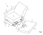
- Fig. 1 is a chair 1 shown in the form of an armchair. Alternatively, it could also be a sofa or a reclining furniture, such as a couch or the like act.
- the seat 1 comprises a backrest 2, a seat 3, an adjustable foot part 4 and two side parts 5 at the opposite ends of the seat 1.
- the two side parts 5 are connected to each other via a chassis 6, which the backrest 2, the seat 3 and the foot part 4 carries.
- the backrest 2, the seat 3 and the foot part 4 are fixed to the chassis 6 via at least one pivot fitting and / or functional fitting. For better clarity, one of the two side parts 5 is shown in the unconnected state.
- the chassis By the connection between the side parts 5 and the chassis 6, a kind of frame or frame structure for the seating 1 is formed, which serves to stiffen the chair 1.
- the chassis could be provided with at least one foot be and the attachments of the chair, such as the backrest, the seat, the footboard and the side panels, supported by the chassis against the ground.
- the illustrated and so far preferred side parts 5 have two feet 7, with which the side parts 5 stand up on the ground.
- the tops of the side parts 5 are formed as armrests 8. But it could also be provided separate armrests or waived entirely on armrests.
- the side part 5 has a connection plate 9.
- a projection 10 in the form of a hook-shaped finger is provided, which, starting from the connection plate 9, extends away from the side part 5, specifically in the direction of the opposite side part 5.
- the finger bends downwards, so that the outer end of the projection 10 extends in the direction of its free end to the base of the chair 1.
- two pin elements 11 are provided on the connection plate 9 of the illustrated and so far preferred side part 5, which likewise extend away from the connection plate 9 of the side part 5, in the direction of the opposite side part 5.
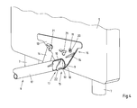
- the illustrated and insofar preferred chassis 6 is formed in the form of a cross-member, which extends between the two side parts 5 of the chair 1.
- the chassis 6 is designed substantially as a tubular hollow profile 12 with a substantially circular cross-section.
- the chassis 6 each have a connection plate 13, which are connected via reinforcing struts 14 with the hollow section 12. Via the connection plates 13, at least partially a connection of the chassis 6 to the side parts 5 can be achieved.
- the chassis 6 is made in the illustrated and so far preferred seating 1 made of steel.
- Fig. 3 is the side part 5 and the chassis 6 shown in a position when connecting together. This is, if necessary, a starting position.
- a first connection 15 is first joined, even if it is not joined at the same time.
- the first connection 15 is a pivotal connection, which allows pivoting of the side part 5 relative to the chassis 6 from a starting position to a locking position without having to solve the first connection 15.
- a second connection 16 and a third connection 17 between the chassis 6 and the side part 5 can then additionally be provided.
- first connection 15 is also a connector since the first connection 15 by partial insertion of the side part 5 in the chassis 6, more precisely by inserting the projection 10 of the side part 5 in the hollow section 12 of the chassis 6 is formed.
- the projection 10 can be inserted up to an end stop 18 in the chassis 6, which is formed by the system of the two connection plates 9,13 together.
- the end stop 18 ultimately forms a positive connection in the insertion direction of the projection 10 in the hollow section 12 of the chassis 6.
- This positive connection and / or the insertion direction can be parallel to the hollow profile 12 or parallel to the transverse direction Q of the chair 1, wherein the transverse direction Q of the chair 1, the two side panels 5 can cut perpendicularly in the locking position.
- the insertion of the side part 5 in the chassis 6 takes place in the illustrated and so far preferred seating 1 with slightly inclined at the top side part 5.
- the position of the side part 5 can form a starting position, from which the side part 5 in the locking position for connecting further connections and is pivoted to the final joining of the first connection 15.
- In the inserted state of the first connection 15 is the projection 10 of the side wall 5 with a lower stop surface 19 on the hollow section 12 of the chassis 6 on.
- the lower stop surface 19 and the hollow profile 12 thus form a positive connection in the vertical direction V down.
- the axis of rotation of the side part 5 parallel to the hollow section 12 and / or parallel to the transverse direction Q be aligned of the chair 1.
- the side member 5 can thus be easily rotated during or after pivoting from the starting position to the locking position to allow easy joining of the second connection 16 and the third connection 17.
- the second connection 16 has in the illustrated and so far preferred seating 1 two bolt elements 11, which reach through in the locking position through openings 20 in the connection plate 13 of the chassis 6.
- the bolt elements 11 have internal threads into which screws 6, in the present case in the form of thumbscrews, are screwed in from the side of the chassis 6 in order to fix the side part 5 positively in the locking position and to pivot the side part 5 back out of the locking position into the starting position prevent.
- the second connection 16 provides in the assembled state a positive connection in three pairs of mutually opposite directions, namely for example in the vertical direction V, in the transverse direction Q of the chair 1 and in the longitudinal direction L of the chair 1, that is substantially parallel to the side members. 5
- the third connection 17 is closed by pivoting the side member 5 in the locking position and engagement of the free downward end of the projection 10 in the form of a hook-shaped finger in a receptacle 22 in the form of an opening in the chassis 6.
- a positive connection in two pairs of opposite directions is provided, in the transverse direction Q and the longitudinal direction L of the chair 1 and in a horizontal plane.
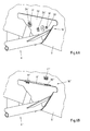
- the first connection 15 and the third connection 17 between the chassis 6 and the side part 5 are in detail in the Fig. 5A-B shown.
- the Fig. 5A shows a vertical sectional view through the chassis 6, while the Fig. 5B shows a view from below.
- the projection 10 accommodated in the receptacle 22 of the hollow profile 12 of the chassis 6 has an upper abutment surface 23 and a lower abutment surface 19, which are in abutment or essentially in contact with the hollow profile 12.
- a preferably substantially play-free positive connection in a vertical direction V is provided with a horizontal base. Due to the circular cross section of the hollow profile 12, a positive connection in the longitudinal direction L of the seat 1 is also provided, preferably perpendicular to the vertical positive fit.
- the third connection 17 thus forms a form fit in a plane parallel to the ground and / or, if necessary, in a transverse direction Q and a longitudinal direction L of the seat 1. This is by the engagement of the free end of the projection 10 in the form of a hook-shaped finger in the opening 22nd at the bottom of the chassis 6, more precisely, the hollow profile 12, achieved. This happens at the right orientation of the side part 5 relative to the chassis 6 automatically with the pivoting of the side part 5 in the locked position.
- the form-fitting of the illustrated and insofar preferred third connection 17 are not formed substantially free of play. Nevertheless, the existing game is relatively small.
- FIG. 6A-B Two alternative embodiments of the second connection 16 ', 16 "are shown between the chassis 6', 6" and the side part 5 ', 5 " Fig. 6A are also two pin members 11 'on the side part 5' are provided, which engage in the locking position of the side part 5 'relative to the chassis 6' through openings 20 'in the connection plate 13' of the chassis 6 '.
- the bolt elements 11 ' are on the side of the side 5' remote from the openings 20 'by securing means 24', secured in the form of quick fasteners or metal nuts form-fitting against subsequent withdrawal.
- Fig. 6B has the connection plate 9 "of the side part
- the pushed through bolt elements 11 "then form a positive locking, which blocks pivoting back of the side part 5" in the starting position.
- the bolt elements 11 in the insertion direction as well as in the extension direction positively and / or non-positively secured in the openings 20".
Landscapes
- Engineering & Computer Science (AREA)
- General Engineering & Computer Science (AREA)
- Mechanical Engineering (AREA)
- Chairs For Special Purposes, Such As Reclining Chairs (AREA)
Applications Claiming Priority (1)
| Application Number | Priority Date | Filing Date | Title |
|---|---|---|---|
| DE102014103537.2A DE102014103537A1 (de) | 2014-03-14 | 2014-03-14 | Sitzmöbel und/oder Liegemöbel mit einem Chassis und einem damit verbundenen Seitenteil |
Publications (1)
| Publication Number | Publication Date |
|---|---|
| EP2921082A1 true EP2921082A1 (fr) | 2015-09-23 |
Family
ID=52477670
Family Applications (1)
| Application Number | Title | Priority Date | Filing Date |
|---|---|---|---|
| EP15155584.4A Withdrawn EP2921082A1 (fr) | 2014-03-14 | 2015-02-18 | Meuble destiné à s'asseoir ou s'allonger doté d'un cadre et élément latéral y étant relié |
Country Status (2)
| Country | Link |
|---|---|
| EP (1) | EP2921082A1 (fr) |
| DE (1) | DE102014103537A1 (fr) |
Families Citing this family (2)
| Publication number | Priority date | Publication date | Assignee | Title |
|---|---|---|---|---|
| GB2585625B (en) * | 2019-03-14 | 2023-05-10 | Furniture Components Direct Ltd | A modular furniture system and an article of furniture |
| US12532968B1 (en) * | 2025-06-27 | 2026-01-27 | Wenhe Peng | Sofa |
Citations (4)
| Publication number | Priority date | Publication date | Assignee | Title |
|---|---|---|---|---|
| DE1729988A1 (de) * | 1968-03-16 | 1971-07-08 | Happich Gmbh Gebr | Leicht loes- und befestigbare,gepolsterte Armlehne,insbesondere fuer Sitzmoebel |
| US5544940A (en) * | 1994-12-12 | 1996-08-13 | Quickie Designs Inc. | Pivotal rear latch assembly for an armrest apparatus for a wheelchair |
| DE10144569A1 (de) * | 2000-09-20 | 2002-04-04 | Hasag Moebel Gmbh Attnang Puch | Möbel |
| DE20319481U1 (de) | 2003-12-16 | 2004-02-26 | Ferdinand Lusch Gmbh & Co Kg | Mehrsitziges Sofa |
-
2014
- 2014-03-14 DE DE102014103537.2A patent/DE102014103537A1/de not_active Withdrawn
-
2015
- 2015-02-18 EP EP15155584.4A patent/EP2921082A1/fr not_active Withdrawn
Patent Citations (4)
| Publication number | Priority date | Publication date | Assignee | Title |
|---|---|---|---|---|
| DE1729988A1 (de) * | 1968-03-16 | 1971-07-08 | Happich Gmbh Gebr | Leicht loes- und befestigbare,gepolsterte Armlehne,insbesondere fuer Sitzmoebel |
| US5544940A (en) * | 1994-12-12 | 1996-08-13 | Quickie Designs Inc. | Pivotal rear latch assembly for an armrest apparatus for a wheelchair |
| DE10144569A1 (de) * | 2000-09-20 | 2002-04-04 | Hasag Moebel Gmbh Attnang Puch | Möbel |
| DE20319481U1 (de) | 2003-12-16 | 2004-02-26 | Ferdinand Lusch Gmbh & Co Kg | Mehrsitziges Sofa |
Also Published As
| Publication number | Publication date |
|---|---|
| DE102014103537A1 (de) | 2015-09-17 |
Similar Documents
| Publication | Publication Date | Title |
|---|---|---|
| EP2298133B1 (fr) | Chaise | |
| DE3875822T2 (de) | Trennwand, insbesondere fuer bueros. | |
| EP4064938A1 (fr) | Traverse et meuble modulaire | |
| EP4064937B1 (fr) | Meuble en kit | |
| DE19504542B4 (de) | Stuhl | |
| EP2796074A1 (fr) | Siège doté d'un dossier facile à monter | |
| EP2921082A1 (fr) | Meuble destiné à s'asseoir ou s'allonger doté d'un cadre et élément latéral y étant relié | |
| EP2921079B1 (fr) | Meubles destiné à s'asseoir ou s'allonger dotée d'une pièce rapportée | |
| DE3102027A1 (de) | Vorrichtung zur verbindung zweier streben unter zwischenfuegung einer zu diesen senkrechten stuetze | |
| EP2961251A1 (fr) | Construction de liaison de pièces de tôle adjacentes et boîtier en tôle les comprenant | |
| EP1649786A1 (fr) | Ferrure pour l'articulation de supports des lattes d'un sommier | |
| DE1988325U (de) | Langgestrecktes moebelteil mit steckverbindung. | |
| DE2930140C2 (de) | Sitzmöbel | |
| CH717986A1 (de) | Kreuzverband und Möbelbausatz. | |
| DE102017102921B4 (de) | Seitensicherung für ein Bett und Verfahren zum Aufbau | |
| DE20109280U1 (de) | Steh-/Sitzplatz-Einrichtung | |
| DE29820566U1 (de) | Regalvorrichtung | |
| DE8123589U1 (de) | "steharbeitssitz" | |
| DE4322335C1 (de) | Reihenverbindung für Gestelle wie Stuhl- und Tischgestelle | |
| DE19931041A1 (de) | Unterkonstruktion für ein Verkleidungssystem für eine Wanne | |
| DE102012106388A1 (de) | Vorrichtung zur Ausrichtung eines Sitzringes | |
| DE2225955A1 (de) | Montagewand | |
| DE4014834A1 (de) | Stahlrohrbett | |
| DE29918803U1 (de) | Faltschrank | |
| DE7921279U1 (de) | Sitzmoebel |
Legal Events
| Date | Code | Title | Description |
|---|---|---|---|
| PUAI | Public reference made under article 153(3) epc to a published international application that has entered the european phase |
Free format text: ORIGINAL CODE: 0009012 |
|
| AK | Designated contracting states |
Kind code of ref document: A1 Designated state(s): AL AT BE BG CH CY CZ DE DK EE ES FI FR GB GR HR HU IE IS IT LI LT LU LV MC MK MT NL NO PL PT RO RS SE SI SK SM TR |
|
| AX | Request for extension of the european patent |
Extension state: BA ME |
|
| 17P | Request for examination filed |
Effective date: 20160321 |
|
| RBV | Designated contracting states (corrected) |
Designated state(s): AL AT BE BG CH CY CZ DE DK EE ES FI FR GB GR HR HU IE IS IT LI LT LU LV MC MK MT NL NO PL PT RO RS SE SI SK SM TR |
|
| STAA | Information on the status of an ep patent application or granted ep patent |
Free format text: STATUS: EXAMINATION IS IN PROGRESS |
|
| 17Q | First examination report despatched |
Effective date: 20170206 |
|
| GRAP | Despatch of communication of intention to grant a patent |
Free format text: ORIGINAL CODE: EPIDOSNIGR1 |
|
| STAA | Information on the status of an ep patent application or granted ep patent |
Free format text: STATUS: GRANT OF PATENT IS INTENDED |
|
| INTG | Intention to grant announced |
Effective date: 20190103 |
|
| STAA | Information on the status of an ep patent application or granted ep patent |
Free format text: STATUS: THE APPLICATION IS DEEMED TO BE WITHDRAWN |
|
| 18D | Application deemed to be withdrawn |
Effective date: 20190514 |
|
| 19U | Interruption of proceedings before grant |
Effective date: 20190601 |
|
| 19W | Proceedings resumed before grant after interruption of proceedings |
Effective date: 20240301 |
|
| PUAJ | Public notification under rule 129 epc |
Free format text: ORIGINAL CODE: 0009425 |
|
| 32PN | Public notification |
Free format text: MITTEILUNG GEMAESS REGEL 142 EPUE (WIEDERAUFNAHME DES VERFAHRENS NACH REGEL 142 (2) EPUE VOM 28.09.2023) |
|
| STAA | Information on the status of an ep patent application or granted ep patent |
Free format text: STATUS: GRANT OF PATENT IS INTENDED |
|
| PUAJ | Public notification under rule 129 epc |
Free format text: ORIGINAL CODE: 0009425 |
|
| 32PN | Public notification |
Free format text: FESTSTELLUNG EINES RECHTSVERLUSTS NACH REGEL 112(1) EPUE (EPA FORM 2524 VOM 21.08.2024) |
|
| STAA | Information on the status of an ep patent application or granted ep patent |
Free format text: STATUS: THE APPLICATION IS DEEMED TO BE WITHDRAWN |
|
| R18D | Application deemed to be withdrawn (corrected) |
Effective date: 20241202 |