EP2921128B1 - Outil guide - Google Patents
Outil guide Download PDFInfo
- Publication number
- EP2921128B1 EP2921128B1 EP13855881.2A EP13855881A EP2921128B1 EP 2921128 B1 EP2921128 B1 EP 2921128B1 EP 13855881 A EP13855881 A EP 13855881A EP 2921128 B1 EP2921128 B1 EP 2921128B1
- Authority
- EP
- European Patent Office
- Prior art keywords
- section
- guide
- cutting
- pole
- handle
- Prior art date
- Legal status (The legal status is an assumption and is not a legal conclusion. Google has not performed a legal analysis and makes no representation as to the accuracy of the status listed.)
- Active
Links
- 239000007943 implant Substances 0.000 claims description 75
- 230000001105 regulatory effect Effects 0.000 claims description 10
- 238000002513 implantation Methods 0.000 claims description 6
- 230000007423 decrease Effects 0.000 claims description 2
- 238000000034 method Methods 0.000 description 15
- 230000004048 modification Effects 0.000 description 14
- 238000012986 modification Methods 0.000 description 14
- 210000000988 bone and bone Anatomy 0.000 description 12
- 210000000214 mouth Anatomy 0.000 description 9
- 230000033228 biological regulation Effects 0.000 description 8
- 230000002093 peripheral effect Effects 0.000 description 7
- 230000000740 bleeding effect Effects 0.000 description 5
- 210000003128 head Anatomy 0.000 description 5
- 230000000007 visual effect Effects 0.000 description 5
- 238000010586 diagram Methods 0.000 description 4
- 210000002698 mandibular nerve Anatomy 0.000 description 4
- 210000004086 maxillary sinus Anatomy 0.000 description 4
- 238000001356 surgical procedure Methods 0.000 description 4
- 210000000332 tooth crown Anatomy 0.000 description 4
- 238000002591 computed tomography Methods 0.000 description 2
- 206010061274 Malocclusion Diseases 0.000 description 1
- 210000004763 bicuspid Anatomy 0.000 description 1
- 230000015572 biosynthetic process Effects 0.000 description 1
- 238000013170 computed tomography imaging Methods 0.000 description 1
- 230000000694 effects Effects 0.000 description 1
- 238000009434 installation Methods 0.000 description 1
- 210000004373 mandible Anatomy 0.000 description 1
- 238000004904 shortening Methods 0.000 description 1
Images


Classifications
-
- A—HUMAN NECESSITIES
- A61—MEDICAL OR VETERINARY SCIENCE; HYGIENE
- A61C—DENTISTRY; APPARATUS OR METHODS FOR ORAL OR DENTAL HYGIENE
- A61C1/00—Dental machines for boring or cutting ; General features of dental machines or apparatus, e.g. hand-piece design
- A61C1/08—Machine parts specially adapted for dentistry
- A61C1/082—Positioning or guiding, e.g. of drills
- A61C1/084—Positioning or guiding, e.g. of drills of implanting tools
-
- A—HUMAN NECESSITIES
- A61—MEDICAL OR VETERINARY SCIENCE; HYGIENE
- A61C—DENTISTRY; APPARATUS OR METHODS FOR ORAL OR DENTAL HYGIENE
- A61C3/00—Dental tools or instruments
- A61C3/02—Tooth drilling or cutting instruments; Instruments acting like a sandblast machine
-
- A—HUMAN NECESSITIES
- A61—MEDICAL OR VETERINARY SCIENCE; HYGIENE
- A61C—DENTISTRY; APPARATUS OR METHODS FOR ORAL OR DENTAL HYGIENE
- A61C8/00—Means to be fixed to the jaw-bone for consolidating natural teeth or for fixing dental prostheses thereon; Dental implants; Implanting tools
- A61C8/0089—Implanting tools or instruments
Definitions
- the present invention relates to a guide jig for guiding a cutting burr attached to a handpiece when forming an implant cavity (implantation hole) into which an implant (artificial tooth) is implanted.
- a position, direction and depth of an implant cavity in the alveolar bone are important in avoiding damages to a peripheral region, malocclusion after mounting of an artificial tooth crown or the like.
- implant treatment methods include a method of creating a stent for positioning an implant cavity on a patient's tooth form model before carrying out an implanting surgery and a method of creating a stent using a CT scan image of the jawbone before carrying out an implanting surgery (see Patent Literature 1). Furthermore, a method without using any stent before carrying out implanting surgery is also known.
- Both WO 94/00073 and DE 10 2007 044 781 discloses a guide jig for guiding a drill bit attached to a handpiece when forming an implant cavity at an implantation position of an implant, the guide jig comprising: an elongated handle section; a pole section that supports an end side of the handle section; and a guide section that guides the drill bit on the end side of the handle section.
- the method of creating a stent on a patient's tooth form model may not be sufficiently effective during surgery such as the position of a guide hole formed in the stent being slightly deviated from the implantation position of the implant cavity.
- it may be difficult to make fine adjustments of the depth of the implant cavity and when the distance to the mandibular nerve or maxillary sinus is short, it may be necessary to mount a stopper on the cutting burr with the stent removed and make fine adjustments of the depth. For this reason, it may take labor and time to adjust the depth, thereby requiring an extended surgical time and increasing the patient's burden.
- the method of creating a stent using a CT scan image of the jawbone described in Patent Literature 1 makes it possible to form an appropriate guide hole in the stent using digital data, thereby improve the accuracy of the position, direction and depth of the implant cavity and reduce the surgical time, whereas the method requires equipment such as a CT imaging device, which may increase an installation cost.
- the implant cavity may not be formed appropriately because cutting is done based on a visual check. Particularly, bleeding or the like may make it difficult to visually inspect whether the tip of the cutting burr contacts an appropriate position or not.
- the present invention has been implemented in view of the above problems, and it is an object of the present invention to provide a guide jig capable of appropriately forming an implant cavity without forming any stent and shortening a surgical time at a low cost.
- a guide jig according to the present invention is defined in appended independent claim 1.
- the pole section protrudes from the end side of the handle section in a direction opposite to the direction of cutting by the cutting burr. According to this configuration, since the handpiece comes into contact with the pole section that supports the handle section on the alveolar bone, it is possible to stably receive an impact from the handpiece and thereby prevent shaking of the handle section due to hand movement.
- the pole section has an overall length corresponding to a target depth of the implant cavity. According to this configuration, since the handpiece comes into contact with the protruding part of the pole section, it is possible to form an implant cavity to an appropriate depth without the implant cavity being cut to deeper than a target depth.
- the pole section is provided at an end of the handle section and the guide section is provided at a back side of the pole section seen from the handle section side. According to this configuration, it is possible to appropriately guide the cutting burr when forming an implant cavity for a maxillary/mandibular anterior tooth.
- the pole section is provided at the end of the handle section and the guide section is provided in parallel with the pole section seen from the handle section side. According to this configuration, it is possible to appropriately guide the cutting burr when forming an implant cavity for a maxillary/mandibular molar.
- the cutting burr includes a chuck section attached to the handpiece and a cutting section that extends from the chuck section in the cutting direction, an outside diameter of the cutting section is smaller than an outside diameter of the chuck section, and the guide section has a guide surface smaller than the outside diameter of the chuck section and corresponding to the outside diameter of the cutting section.
- the guide section protrudes above the pole section in a direction opposite to the cutting direction. According to this configuration, the chuck section comes into contact with the guide section before the handpiece comes into contact with the pole section, and it is thereby possible to regulate the depth of cutting by the cutting burr.
- the guide jig of the present invention it is possible to move the guide jig while checking an occlusal relationship with an opposing tooth and guide the cutting burr to an appropriate position, and thereby appropriately form an implant cavity. Furthermore, since the depth of cutting by the cutting burr is regulated, it is possible to shorten the surgical time without unintentionally damaging the peripheral region. Moreover, it is possible to eliminate the necessity for creation of a stent or sophisticated equipment, and thereby achieve a cost reduction.
- FIG. 1 is a perspective view of a guide jig according to the present embodiment.
- FIG. 2 is a side view of the guide jig according to the present embodiment.
- description will be given by taking a guide jig for a maxillary/mandibular anterior tooth as an example.
- a guide jig 1 is intended to be inserted into an oral cavity of a patient and guide cutting of an implant cavity, and is provided with a pole section 12 and a guide section 13 on an end side of a handle section 11 which is formed of an elongated fashion.
- the handle section 11 has a rectangular cross section and is long enough to be held at a base side thereof and moved with the end side thereof inserted in the oral cavity.
- the pole section 12 is provided at the end of the handle section 11 to support the end side of the handle section 11 on the alveolar bone 25 (see FIG. 4 ).
- the pole section 12 is formed into a columnar shape and fixed to the end of the handle section 11 in an upright position.
- a tapered abutting section 17 which protrudes from an undersurface 15 of the handle section 11, and a diameter of which decreases downward, is formed on one end side of the pole section 12. With this abutting section 17 abutting on the alveolar bone 25, the pole section 12 is tiltably and rotatably supported with the abutting section 17 as a fulcrum.
- a regulation surface 18 is formed on the other end side of the pole section 12, which protrudes from a top surface 16 of the handle section 11 to regulate the amount of cutting by a cutting burr 21 (see FIG. 4 ). The regulation surface 18 comes into contact with a head 23 of a handpiece 22 during cutting of the implant cavity and thereby regulates the descent of the cutting burr 21 to a depth deeper than a target depth.
- the pole section 12 has a length corresponding to the target depth of the implant cavity. That is, the pole section 12 is designed by taking into account the length of the cutting burr 21 that protrudes from the head 23 of the handpiece 22 and the target depth of the implant cavity. This prevents the implant cavity from being cut deeper than the target depth and allows the implant cavity of an appropriate depth to be formed. Therefore, when the distance to the mandibular nerve or maxillary sinus is small or the like, it is possible to prevent the peripheral region from being damaged. Note that instead of the overall length of the pole section 12, the length of the cutting burr 21 may be changed to adjust the depth of the implant cavity.
- the pole section 12 is provided with the guide section 13 that guides the cutting burr 21, at the back side seen from the handle section 11 side.
- the guide section 13 is formed into a cylindrical tubular shape and fixed to an outer circumferential surface of the pole section 12 so as to be in parallel with the pole section 12.
- the guide section 13 has substantially the same length as a longitudinal width of the handle section 11 and is positioned at a position lower than the regulation surface 18 of the pole section 12.
- the inner diameter of the inner surface of the guide section 13 is formed so as to match the outside diameter of the cutting burr 21.
- the cutting burr 21 is inserted into the guide section 13 and cutting by the cutting burr 21 is thereby guided along the inner surface of the guide section 13.
- the guide jig 1 configured in this way is inserted into the oral cavity of the patient and supported onto the alveolar bone 25 by the pole section 12.
- the orientation and position of the guide section 13 are adjusted by moving the handle section 11 with the abutting section 17 as a fulcrum. Since the orientation and position of the guide section 13 can be easily adjusted, it is possible to reduce the operator's burden.
- FIG. 3 shows top views of a few types of guide jigs according to the present embodiment.
- FIG. 3A illustrates a guide jig for a maxillary/mandibular anterior tooth
- FIG. 3B illustrates a modification example of a guide jig for a maxillary/mandibular anterior tooth
- FIG. 3C illustrates a guide jig for a maxillary/mandibular molar. Note that identical names are assigned identical reference numerals for convenience of description hereinafter.
- the guide section 13 is provided at the back side of the pole section 12 in one line seen from the handle section 11 side. For this reason, when forming implant cavities for the maxillary/mandibular anterior teeth arranged in line in the front of the oral cavity, this makes it easier to appropriately guide the cutting burr 21 (see FIG. 4 ) while checking the position and direction of the implant cavities.
- the guide section 13 may be provided at the back side of the pole section 12 seen from the handle section 11 side or the guide section 13 may be provided at the diagonally back side of the pole section 12 as the guide jig 1 shown in FIG. 3B .
- the guide jig 1 shown in FIG. 3B may also be used for maxillary/mandibular premolars.
- the guide section 13 is provided in parallel with the pole section 12 seen from the handle section 11 side. For this reason, when forming implant cavities for the maxillary/mandibular molars arranged at the back side in the oral cavity, this makes it easier to appropriately guide the cutting burr 21 while checking the position and direction of the implant cavities.
- the guide section 13 is provided on the right side of the pole section 12 and is used for the mandible right side molar and maxillary left side molar.
- the guide section 13 is provided on the left side of the pole section 12 and is used for the mandibular left side molar and maxillary right side molar.
- each guide jig 1 is used according to the positions of teeth in the oral cavity.
- the implant cavity is formed by expanding the hole diameter in several stages.
- each guide jig 1 is provided with the guide section 13 having an inner diameter that matches the diameter of the cutting burr 21.
- different guide jigs 1 are used for when forming an implant cavity 28 using the cutting burr 21 having a diameter of 2 mm and when expanding the diameter of the implant cavity 28 using the cutting burr 21 having a diameter of 3 mm.
- the pole section 12 is preferably designed to have a diameter of 2 mm and an overall length of 10 mm
- the guide section 13 is preferably designed to have an overall length of 5 mm.
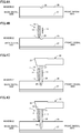
- FIG. 4 shows diagrams describing the method of using the guide jig according to the present embodiment.
- FIG. 4 an example of forming an implant cavity for the mandibular right side molar will be described, but the same method of using the guide jig is used for when forming implant cavities for other teeth.
- a case where the guide jig at the top of FIG. 3C is used will be described.
- a marking hole 26 having a diameter 2 mm and a depth of on the order of 1 mm is formed at an implantation position of an implant on the alveolar bone 25 using a round bar (not shown).
- the position at which the implant cavity 28 is formed is defined on the alveolar bone 25.
- the actual surface of the alveolar bone 25 is not flat and bleeding is often observed, and therefore the operator can check the implantation position of the implant using this hole 26 as a clue.
- the guide jig 1 for the cutting burr 21 having a diameter of 2 mm is inserted into the oral cavity and the tapered abutting section 17 of the pole section 12 is caused to abut thereon at a position 1 mm behind (distal) the hole 26.
- the end side of the guide jig 1 is stably supported on the alveolar bone 25.
- the cutting burr 21 having a diameter of 2 mm is inserted into the hole of the guide section 13 with the handle section 11 being fixed. Then, by driving handpiece 22, the cutting burr 21 starts forming an implant cavity. Since the guide section 13 guides the cutting burr 21 in parallel with the pole section 12, it is possible to check a cutting situation of the implant cavity 28 by visually checking the other end side (top end side) of the pole section 12. Therefore, it is possible to avoid the difficulty in visual checking due to bleeding or the like unlike the case where a cutting situation of the implant cavity is checked by directly watching the tip of the cutting burr 21.
- the guide jig 1 for the cutting burr 21 having a diameter of 3 mm is inserted into the oral cavity and the diameter of the implant cavity 28 is enlarged to 3 mm using a similar procedure.
- the implant cavity 28 is expanded using a final cutting burr according to the implant system and the formation of the implant cavity 28 is completed. After that, an implant is implanted into the implant cavity 28 and a superstructure (artificial tooth crown) is mounted via an abutment.
- the guide jig 1 it is possible to move the guide jig 1 while checking the occlusal relationship with the opposing tooth and guide the cutting burr 21 to an appropriate position.
- the position and direction of the implant cavity 28 can be checked by visually checking the pole section 12 that protrudes from the end side of the handle section 11.
- the pole section 12 comes into contact with the handpiece and it is thereby possible to regulate the cutting depth of the cutting burr 21. This eliminates the necessity for depth adjustments, can thereby reduce the surgical time and avoid unintentional damages to the peripheral region. This also eliminates the necessity for creation of a stent or sophisticated equipment.
- the present embodiment has adopted the configuration in which the head 23 of the handpiece 22 comes into contact with the regulation surface 18 of the pole section 12 and the descent of the cutting burr 21 is thereby regulated, but the present invention is not limited to this configuration.
- the configuration may be such that the descent of the cutting burr 21 is regulated by the guide section 13.
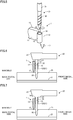
- a predetermined length of the cutting burr 21 on a base side corresponds to a chuck section 31 mounted to the handpiece 22 and a portion extending downward (cutting direction) from the chuck section 31 corresponds to a cutting section 32 having a cutting blade.
- the outside diameter of the cutting section 32 is smaller than the outside diameter of the chuck section 31 and a step is formed on a boundary between the cutting section 32 and the chuck section 31.
- the outside diameter of the chuck section 31 is 2.2 mm and the outside diameter of the cutting section 32 is 2.0 mm.
- the cutting section 32 need not be provided with a cutting blade throughout the overall length, and the cutting blade may be provided from some midpoint toward the tip as in the case of the present embodiment.
- the inner circumferential surface of the guide section 13 constitutes a guide surface 33 which guides the cutting section 32 and is formed to be smaller than the outside diameter of the chuck section 31 to correspond to the outside diameter of the cutting section 32.
- the guide surface 33 is formed to have a diameter of 2.05 mm provided with a tiny play with respect to the cutting section 32.
- the guide surface 33 which is the inner circumferential surface of the guide section 13 is formed so as to allow only the cutting section 32 except the chuck section 31 of the cutting burr 21 on the base side to be inserted therethrough.
- the top surface 34 of the guide section 13 functions as a regulation surface that regulates the amount of cutting by the cutting burr 21.
- the chuck section 31 comes into contact with a top surface 34 of this guide section 13 during cutting of the implant cavity 28 and the descent of the cutting burr 21 to a position deeper than a target depth is thereby regulated.
- the pole section 12 protrudes above the guide section 13, but the present invention is not limited to this configuration.
- the guide section 13 may protrude above the pole section 12 as shown in another modification example in FIG. 7 .
- the chuck section 31 comes into contact with the guide section 13 before the handpiece 22 comes into contact with the pole section 12, whereby the cutting depth of the cutting burr 21 is regulated.
- the descent of the cutting burr 21 can be regulated by the guide section 13 no matter if the cutting burr 21 is of a different manufacturer.
- the top surface of the guide section 13 may be formed to be flush with the top surface of the pole section 12.
- the present embodiment and the modification examples have described a configuration in which the pole section 12 protrudes from the end side of the handle section 11 in a direction opposite to the direction of cutting by the cutting burr 21, but the present invention is not limited to this configuration.
- At least one of the pole section 12 and the guide section 13 may protrude from the end side of the handle section 11 in a direction opposite to the direction of cutting by the cutting burr 21.
- both the pole section 12 and the guide section 13 may protrude from the end side of the handle section 11 to form the regulation surface 18 flush with each other or only the guide section 13 may protrude from the end side of the handle section 11.
- the present embodiment and the modification examples have described a configuration in which the pole section 12 is provided at the end of the handle section 11 and the guide section 13 is provided on the outer circumferential surface of the pole section 12, but the present invention is not limited to this configuration.
- the pole section 12 may be provided at any position if at least the end side of the handle section 11 can be supported.
- the guide section 13 can be provided in whatever way if at least the cutting burr 21 can be guided on the end side of the handle section 11.
- the present embodiment and the modification examples have described a configuration in which the handle section 11 is formed to have an elongated rectangular cross section, but the present invention is not limited to this shape.
- the handle section 11 may only be long enough to be held at the base side thereof and moved with the end side thereof inserted in the oral cavity.
- the present embodiment and the modification examples have described the pole section 12 formed into a columnar shape, but the present invention is not limited to this shape.
- the pole section 12 may have any shape as long as the pole section 12 can support the end side of the handle section 11.
- the abutting section 17 of the pole section 12 is not limited to the tapered shape, either.
- the present embodiment and the modification examples have described the guide section 13 shaped into a tubular shape, but the present invention is not limited to this shape.
- the guide section 13 may have any shape as long as the guide section 13 can guide the cutting burr 21 on the end side of the handle section 11.
- the present embodiment and the modification examples have described a configuration in which the guide section 13 is provided at the back side of or in parallel with the pole section 12 seen from the handle section 11 side, but the present invention is not limited to this configuration.
- the position of the guide section 13 with respect to the pole section 12 can be changed as appropriate according to the position of the tooth or the like.
- the present embodiment has described a configuration in which the pole section 12 has a length corresponding to the target depth of the implant cavity 28, but present invention is not limited to this configuration.
- the pole section 12 may have a length whereby cutting by the cutting burr 21 can be regulated to an extent that the implant cavity 28 does not become excessively deep. In this case, the head 23 of the handpiece 22 need not come into contact with the regulation surface 18 of the pole section 12.
- the present embodiment and the modification examples have described a configuration in which the tip of the abutting section 17 of the pole section 12 is formed on the central axis of the pole section 12, but the present invention is not limited to this configuration.
- the tip of the abutting section 17 may also be formed at a position decentered from the central axis of the pole section 12.
- the tip of the abutting section 17 is formed on the central axis of the pole section 12, and in the case of the guide jig 1 for the cutting burr 21 having a diameter of 3 mm, the tip of the abutting section 17 is formed at a position decentered from the central axis of the pole section 12.
- the tip of the abutting section 17 of the guide jig 1 for the cutting burr 21 having a diameter of 3 mm is formed at a position decentered from the central axis of the pole section 12.
- the present invention has an effect of being able to appropriately form an implant cavity without forming any stent and further shorten the surgical time at low cost, and is especially useful for a guide jig that guides a cutting burr of a handpiece when forming an implant cavity.
Landscapes
- Health & Medical Sciences (AREA)
- Oral & Maxillofacial Surgery (AREA)
- Dentistry (AREA)
- Epidemiology (AREA)
- Life Sciences & Earth Sciences (AREA)
- Animal Behavior & Ethology (AREA)
- General Health & Medical Sciences (AREA)
- Public Health (AREA)
- Veterinary Medicine (AREA)
- Orthopedic Medicine & Surgery (AREA)
- Dental Prosthetics (AREA)
Claims (6)
- Un gabarit de guidage pour guider une barre de coupe fixée à une pièce à main lors de la formation d'une cavité d'implant à une position d'implantation d'un implant, le gabarit de guidage comprenant :une section de manche allongée ;une section de poteau qui supporte une face d'extrémité de la section de manche ; etune section de guidage qui guide la barre de coupe, la section de guidage étant prévue à côté de la section de poteau sur la face d'extrémité de la section de manche, dans laquelle :la section de guidage (13) est prévue sur l'un des côtés arrière de la section de poteau (12), le côté arrière en diagonale de la section de poteau (12), le côté droit et le côté gauche de la section de poteau (12), vu du côté de la section de manche ; dans laquellela section de guidage (13) est prévue parallèlement à la section de poteau (12), vue du côté de la section de manche, de sorte que l'orientation et la position de la section de guidage (13) sont réglables en déplaçant la section de manche (11) avec la section de butée (17) en tant que point d'appui, et dans lequella section de poteau a la forme d'une colonne et est fixée à l'extrémité de la section de manche dans une position verticale,au moins une parmi la section de poteau et la section de guidage dépassant du côté d'extrémité de la section de manche dans une direction opposée à la direction de coupe par la barre de coupe,dans lequel la section de poteau comprend en outre une section de butée formée à une extrémité de la section de poteau, la section de butée étant effilée de sorte qu'un diamètre de la section de butée diminue en taille dans la direction de coupe.
- Le gabarit de guidage selon la revendication 1, dans lequel la section de poteau fait saillie à partir du côté d'extrémité de la section de manche dans la direction opposée à la direction de coupe par la barre de coupe.
- Le gabarit de guidage selon la revendication 1 ou 2, dans lequel la section de guidage comprend une surface pour réguler une quantité de coupe par la barre de coupe.
- Le gabarit de guidage selon la revendication 1, dans lequel la section de poteau est prévue à une extrémité de la section de manche, et la section de guidage est prévue sur un côté arrière de la section de poteau vu depuis un côté de la section de manche.
- Système pour former une cavité d'implant (28), comprenant le gabarit de guidage selon la revendication 1 et la barre de coupe ayant une section de mandrin attachée à la pièce à main et une section de coupe qui s'étend depuis la section de mandrin dans la direction de coupe, dans lequel une marche est formée dans la section de mandrin pour réguler la descente de la barre de coupe en entrant en contact avec la section de guidage.
- Système selon la revendication 5, dans lequel la section de guidage dépasse plus que la section de poteau dans une direction opposée à la direction de coupe.
Applications Claiming Priority (3)
| Application Number | Priority Date | Filing Date | Title |
|---|---|---|---|
| JP2012250805 | 2012-11-15 | ||
| JP2012284861A JP6153721B2 (ja) | 2012-11-15 | 2012-12-27 | ガイド治具 |
| PCT/JP2013/080064 WO2014077172A1 (fr) | 2012-11-15 | 2013-11-07 | Outil guide |
Publications (3)
| Publication Number | Publication Date |
|---|---|
| EP2921128A1 EP2921128A1 (fr) | 2015-09-23 |
| EP2921128A4 EP2921128A4 (fr) | 2016-08-10 |
| EP2921128B1 true EP2921128B1 (fr) | 2019-12-25 |
Family
ID=50731086
Family Applications (1)
| Application Number | Title | Priority Date | Filing Date |
|---|---|---|---|
| EP13855881.2A Active EP2921128B1 (fr) | 2012-11-15 | 2013-11-07 | Outil guide |
Country Status (8)
| Country | Link |
|---|---|
| US (1) | US20150282894A1 (fr) |
| EP (1) | EP2921128B1 (fr) |
| JP (1) | JP6153721B2 (fr) |
| KR (1) | KR102089427B1 (fr) |
| CN (1) | CN105073060B (fr) |
| ES (1) | ES2776030T3 (fr) |
| TW (1) | TWI603719B (fr) |
| WO (1) | WO2014077172A1 (fr) |
Families Citing this family (12)
| Publication number | Priority date | Publication date | Assignee | Title |
|---|---|---|---|---|
| WO2016041802A1 (fr) | 2014-09-16 | 2016-03-24 | Cynora Gmbh | Couche électroluminescente appropriée pour une luminescence vive |
| CN104605949A (zh) * | 2015-02-12 | 2015-05-13 | 张玲 | 拔牙刀防滑脱定位器及使用其的方法 |
| CN105411696A (zh) * | 2016-01-07 | 2016-03-23 | 张英怀 | 牙种植用种植体植入导向器 |
| WO2017203419A1 (fr) * | 2016-05-24 | 2017-11-30 | Azenium Ip Limited | Dispositif et procédé de mise en place d'un implant dans une alvéole dentaire |
| US10016242B2 (en) * | 2016-06-06 | 2018-07-10 | Neocis Inc. | Splint device for forming a fiducial marker for a surgical robot guidance system, and associated method |
| CN107825445B (zh) * | 2017-03-21 | 2024-03-19 | 青岛达芬奇科技有限公司 | 一种多洞物体自动化夹取装置 |
| KR102082947B1 (ko) * | 2017-12-15 | 2020-02-28 | 주식회사 이비아이 | 임플란트시술용 트레파인 가이드 |
| KR102009404B1 (ko) * | 2017-12-15 | 2019-08-12 | 주식회사 이비아이 | 임플란트시술용 드릴가이드 |
| EP3763317B1 (fr) * | 2019-07-08 | 2021-10-20 | Anthogyr | Guide de forage pour implantologie dentaire |
| KR102415024B1 (ko) | 2020-06-26 | 2022-06-29 | 연세대학교 원주산학협력단 | 골전도 임플란트 수직 드릴링 가이드 및 편평도 측정 장치 |
| TWI763053B (zh) * | 2020-09-24 | 2022-05-01 | 巧藝國際有限公司 | 機頭限位導引筒狀結構及其植牙限位工具組和植牙導引限位工具組 |
| DE102022134517A1 (de) * | 2022-12-22 | 2024-06-27 | TRI Dental Implants Int. AG | System und Verfahren zur Vorbereitung und/oder Durchführung einer Zahnimplantatsinsertion |
Family Cites Families (26)
| Publication number | Priority date | Publication date | Assignee | Title |
|---|---|---|---|---|
| US2644235A (en) * | 1952-06-12 | 1953-07-07 | Precious Metals Res Works Inc | Dental paralleling instrument |
| US4323347A (en) * | 1979-08-27 | 1982-04-06 | Ipco Corporation | Dental tool for use with dental retaining splints |
| US4251210A (en) * | 1980-03-10 | 1981-02-17 | Ipco Corporation | Dental positioning device |
| GB9213194D0 (en) * | 1992-06-20 | 1992-08-05 | Univ Manchester | Apparatus for guiding implants |
| US5302122A (en) * | 1993-04-05 | 1994-04-12 | Milne Robert H | Dentistry implant paralleling device and method of installing implants |
| US5741133A (en) * | 1995-12-07 | 1998-04-21 | Gordils; Antonio Jose | Apparatuses and process for parallel placement of bone-integrated cylindrical type implants in dentistry |
| US6062856A (en) * | 1999-05-05 | 2000-05-16 | Sussman; Harold I. | Dental implant hole guide extension |
| AU2002329959A1 (en) * | 2001-08-31 | 2003-03-10 | Leonard Marotta | Stable dental analog systems |
| US6869283B2 (en) * | 2002-01-16 | 2005-03-22 | Harold I. Sussman | Implant hole guide |
| FR2836372B1 (fr) * | 2002-02-28 | 2004-06-04 | Obl | Procede et dispositif pour la mise en place d'implants dentaires |
| US20050282106A1 (en) * | 2004-06-16 | 2005-12-22 | Sussman Harold I | Hole guide for mini and standard dental implants |
| US7682151B2 (en) * | 2005-02-08 | 2010-03-23 | Universidad De Concepcion | Integrated system to stabilize dental prostheses |
| KR100611946B1 (ko) * | 2006-04-27 | 2006-08-11 | 주식회사 메가젠 | 임플란트용 스텐트 |
| JP2008005960A (ja) * | 2006-06-28 | 2008-01-17 | Platon Japan:Kk | 施術用器具 |
| DE102007046638A1 (de) * | 2006-10-02 | 2008-06-05 | Mitterwald, Florian, Dr. | Bohrerführung zur Führung eines Bohrers und Verfahren zum Bohren eines Implantatloches in einen Kieferknochen |
| KR100829244B1 (ko) * | 2006-11-16 | 2008-05-14 | 임두만 | 임플란트 시술용 천공 보조구 |
| JP5028621B2 (ja) * | 2007-03-29 | 2012-09-19 | 国立大学法人 東京医科歯科大学 | サージカルガイド |
| JP2008307281A (ja) | 2007-06-15 | 2008-12-25 | Yuichiro Kawahara | インプラント埋入穴開け術後口腔模型の製造方法、ステントの製造方法、および入れ歯の製造方法 |
| EP2397102A1 (fr) * | 2007-08-22 | 2011-12-21 | Straumann Holding AG | Glissière de foret |
| DE102007044781B4 (de) * | 2007-09-19 | 2015-10-15 | Manfred Nilius | Bohrerpositionier- und Messeinrichtung |
| US7813609B2 (en) * | 2007-11-12 | 2010-10-12 | Lightlab Imaging, Inc. | Imaging catheter with integrated reference reflector |
| WO2009155111A1 (fr) * | 2008-05-30 | 2009-12-23 | Wright Medical Technology, Inc. | Ensemble de guidage de foret |
| WO2010025191A1 (fr) * | 2008-08-29 | 2010-03-04 | Zimmer Dental, Inc. | Système de guide de fraise dentaire |
| EP2196162B1 (fr) * | 2008-12-15 | 2016-10-12 | Straumann Holding AG | Guide-foret |
| KR20110106573A (ko) * | 2010-03-23 | 2011-09-29 | 이준호 | 핸드피스 가이드 스텐트 |
| JP2012147845A (ja) * | 2011-01-17 | 2012-08-09 | Yasuhiro Saimiya | 治療治具 |
-
2012
- 2012-12-27 JP JP2012284861A patent/JP6153721B2/ja not_active Expired - Fee Related
-
2013
- 2013-11-07 WO PCT/JP2013/080064 patent/WO2014077172A1/fr not_active Ceased
- 2013-11-07 CN CN201380059882.2A patent/CN105073060B/zh not_active Expired - Fee Related
- 2013-11-07 KR KR1020157014637A patent/KR102089427B1/ko not_active Expired - Fee Related
- 2013-11-07 EP EP13855881.2A patent/EP2921128B1/fr active Active
- 2013-11-07 US US14/441,729 patent/US20150282894A1/en not_active Abandoned
- 2013-11-07 ES ES13855881T patent/ES2776030T3/es active Active
- 2013-11-15 TW TW102141757A patent/TWI603719B/zh not_active IP Right Cessation
Non-Patent Citations (1)
| Title |
|---|
| None * |
Also Published As
| Publication number | Publication date |
|---|---|
| CN105073060B (zh) | 2018-11-13 |
| KR20150118086A (ko) | 2015-10-21 |
| JP6153721B2 (ja) | 2017-06-28 |
| US20150282894A1 (en) | 2015-10-08 |
| TWI603719B (zh) | 2017-11-01 |
| EP2921128A4 (fr) | 2016-08-10 |
| ES2776030T3 (es) | 2020-07-28 |
| KR102089427B1 (ko) | 2020-03-16 |
| WO2014077172A1 (fr) | 2014-05-22 |
| TW201424700A (zh) | 2014-07-01 |
| CN105073060A (zh) | 2015-11-18 |
| JP2014113429A (ja) | 2014-06-26 |
| EP2921128A1 (fr) | 2015-09-23 |
Similar Documents
| Publication | Publication Date | Title |
|---|---|---|
| EP2921128A1 (fr) | Outil guide | |
| EP2196162B1 (fr) | Guide-foret | |
| KR101566456B1 (ko) | 임플란트용 드릴 및 이를 구비하는 임플란트용 드릴 장치 | |
| TWI563986B (zh) | 植牙手術導引裝置組 | |
| EP3817685B1 (fr) | Guide chirurgical pour implants osseux zygomatiques | |
| KR101763763B1 (ko) | 임플란트 식립위치 가이드기구 | |
| JP5028621B2 (ja) | サージカルガイド | |
| EP2191785B1 (fr) | Broche de fixation | |
| JP2001212158A (ja) | インプラント窩形成用ガイドと形成装置及び形成方法 | |
| JP5616738B2 (ja) | サージカルガイド及び埋入孔穿孔具 | |
| JP5410420B2 (ja) | サージカルガイド | |
| KR100852572B1 (ko) | 치과용 의료 기기 | |
| KR101265819B1 (ko) | 임플란트 시술용 포인트 드릴 보조구 | |
| KR100611946B1 (ko) | 임플란트용 스텐트 | |
| JP2011501998A (ja) | 精密誘導植立のためのインプラント用のステント固定体 | |
| KR101099509B1 (ko) | 치열교정용 지지부재의 고정에 사용되는 지그 | |
| JP6357014B2 (ja) | 測定治具 | |
| WO2011061557A1 (fr) | Dispositif de mise en place d'implants dentaires | |
| KR20240155582A (ko) | 골 삭제 가이드 | |
| KR20190043682A (ko) | 정밀한 치과용 임플란트 시술을 위한 가이드 템플릿 제작용 구강 모델 |
Legal Events
| Date | Code | Title | Description |
|---|---|---|---|
| PUAI | Public reference made under article 153(3) epc to a published international application that has entered the european phase |
Free format text: ORIGINAL CODE: 0009012 |
|
| 17P | Request for examination filed |
Effective date: 20150612 |
|
| AK | Designated contracting states |
Kind code of ref document: A1 Designated state(s): AL AT BE BG CH CY CZ DE DK EE ES FI FR GB GR HR HU IE IS IT LI LT LU LV MC MK MT NL NO PL PT RO RS SE SI SK SM TR |
|
| AX | Request for extension of the european patent |
Extension state: BA ME |
|
| DAX | Request for extension of the european patent (deleted) | ||
| REG | Reference to a national code |
Ref country code: DE Ref legal event code: R079 Ref document number: 602013064466 Country of ref document: DE Free format text: PREVIOUS MAIN CLASS: A61C0003040000 Ipc: A61C0001080000 |
|
| RA4 | Supplementary search report drawn up and despatched (corrected) |
Effective date: 20160707 |
|
| RIC1 | Information provided on ipc code assigned before grant |
Ipc: A61C 1/08 20060101AFI20160701BHEP |
|
| STAA | Information on the status of an ep patent application or granted ep patent |
Free format text: STATUS: EXAMINATION IS IN PROGRESS |
|
| 17Q | First examination report despatched |
Effective date: 20181010 |
|
| GRAP | Despatch of communication of intention to grant a patent |
Free format text: ORIGINAL CODE: EPIDOSNIGR1 |
|
| STAA | Information on the status of an ep patent application or granted ep patent |
Free format text: STATUS: GRANT OF PATENT IS INTENDED |
|
| INTG | Intention to grant announced |
Effective date: 20190718 |
|
| GRAS | Grant fee paid |
Free format text: ORIGINAL CODE: EPIDOSNIGR3 |
|
| GRAA | (expected) grant |
Free format text: ORIGINAL CODE: 0009210 |
|
| STAA | Information on the status of an ep patent application or granted ep patent |
Free format text: STATUS: THE PATENT HAS BEEN GRANTED |
|
| AK | Designated contracting states |
Kind code of ref document: B1 Designated state(s): AL AT BE BG CH CY CZ DE DK EE ES FI FR GB GR HR HU IE IS IT LI LT LU LV MC MK MT NL NO PL PT RO RS SE SI SK SM TR |
|
| REG | Reference to a national code |
Ref country code: GB Ref legal event code: FG4D |
|
| REG | Reference to a national code |
Ref country code: CH Ref legal event code: EP |
|
| REG | Reference to a national code |
Ref country code: AT Ref legal event code: REF Ref document number: 1216290 Country of ref document: AT Kind code of ref document: T Effective date: 20200115 |
|
| REG | Reference to a national code |
Ref country code: IE Ref legal event code: FG4D |
|
| REG | Reference to a national code |
Ref country code: DE Ref legal event code: R096 Ref document number: 602013064466 Country of ref document: DE |
|
| REG | Reference to a national code |
Ref country code: NL Ref legal event code: MP Effective date: 20191225 |
|
| PG25 | Lapsed in a contracting state [announced via postgrant information from national office to epo] |
Ref country code: LV Free format text: LAPSE BECAUSE OF FAILURE TO SUBMIT A TRANSLATION OF THE DESCRIPTION OR TO PAY THE FEE WITHIN THE PRESCRIBED TIME-LIMIT Effective date: 20191225 Ref country code: SE Free format text: LAPSE BECAUSE OF FAILURE TO SUBMIT A TRANSLATION OF THE DESCRIPTION OR TO PAY THE FEE WITHIN THE PRESCRIBED TIME-LIMIT Effective date: 20191225 Ref country code: FI Free format text: LAPSE BECAUSE OF FAILURE TO SUBMIT A TRANSLATION OF THE DESCRIPTION OR TO PAY THE FEE WITHIN THE PRESCRIBED TIME-LIMIT Effective date: 20191225 Ref country code: BG Free format text: LAPSE BECAUSE OF FAILURE TO SUBMIT A TRANSLATION OF THE DESCRIPTION OR TO PAY THE FEE WITHIN THE PRESCRIBED TIME-LIMIT Effective date: 20200325 Ref country code: NO Free format text: LAPSE BECAUSE OF FAILURE TO SUBMIT A TRANSLATION OF THE DESCRIPTION OR TO PAY THE FEE WITHIN THE PRESCRIBED TIME-LIMIT Effective date: 20200325 Ref country code: LT Free format text: LAPSE BECAUSE OF FAILURE TO SUBMIT A TRANSLATION OF THE DESCRIPTION OR TO PAY THE FEE WITHIN THE PRESCRIBED TIME-LIMIT Effective date: 20191225 Ref country code: GR Free format text: LAPSE BECAUSE OF FAILURE TO SUBMIT A TRANSLATION OF THE DESCRIPTION OR TO PAY THE FEE WITHIN THE PRESCRIBED TIME-LIMIT Effective date: 20200326 |
|
| REG | Reference to a national code |
Ref country code: LT Ref legal event code: MG4D |
|
| PG25 | Lapsed in a contracting state [announced via postgrant information from national office to epo] |
Ref country code: HR Free format text: LAPSE BECAUSE OF FAILURE TO SUBMIT A TRANSLATION OF THE DESCRIPTION OR TO PAY THE FEE WITHIN THE PRESCRIBED TIME-LIMIT Effective date: 20191225 Ref country code: RS Free format text: LAPSE BECAUSE OF FAILURE TO SUBMIT A TRANSLATION OF THE DESCRIPTION OR TO PAY THE FEE WITHIN THE PRESCRIBED TIME-LIMIT Effective date: 20191225 |
|
| PG25 | Lapsed in a contracting state [announced via postgrant information from national office to epo] |
Ref country code: AL Free format text: LAPSE BECAUSE OF FAILURE TO SUBMIT A TRANSLATION OF THE DESCRIPTION OR TO PAY THE FEE WITHIN THE PRESCRIBED TIME-LIMIT Effective date: 20191225 |
|
| REG | Reference to a national code |
Ref country code: ES Ref legal event code: FG2A Ref document number: 2776030 Country of ref document: ES Kind code of ref document: T3 Effective date: 20200728 |
|
| PG25 | Lapsed in a contracting state [announced via postgrant information from national office to epo] |
Ref country code: NL Free format text: LAPSE BECAUSE OF FAILURE TO SUBMIT A TRANSLATION OF THE DESCRIPTION OR TO PAY THE FEE WITHIN THE PRESCRIBED TIME-LIMIT Effective date: 20191225 Ref country code: CZ Free format text: LAPSE BECAUSE OF FAILURE TO SUBMIT A TRANSLATION OF THE DESCRIPTION OR TO PAY THE FEE WITHIN THE PRESCRIBED TIME-LIMIT Effective date: 20191225 Ref country code: RO Free format text: LAPSE BECAUSE OF FAILURE TO SUBMIT A TRANSLATION OF THE DESCRIPTION OR TO PAY THE FEE WITHIN THE PRESCRIBED TIME-LIMIT Effective date: 20191225 Ref country code: EE Free format text: LAPSE BECAUSE OF FAILURE TO SUBMIT A TRANSLATION OF THE DESCRIPTION OR TO PAY THE FEE WITHIN THE PRESCRIBED TIME-LIMIT Effective date: 20191225 Ref country code: PT Free format text: LAPSE BECAUSE OF FAILURE TO SUBMIT A TRANSLATION OF THE DESCRIPTION OR TO PAY THE FEE WITHIN THE PRESCRIBED TIME-LIMIT Effective date: 20200520 |
|
| PG25 | Lapsed in a contracting state [announced via postgrant information from national office to epo] |
Ref country code: SM Free format text: LAPSE BECAUSE OF FAILURE TO SUBMIT A TRANSLATION OF THE DESCRIPTION OR TO PAY THE FEE WITHIN THE PRESCRIBED TIME-LIMIT Effective date: 20191225 Ref country code: IS Free format text: LAPSE BECAUSE OF FAILURE TO SUBMIT A TRANSLATION OF THE DESCRIPTION OR TO PAY THE FEE WITHIN THE PRESCRIBED TIME-LIMIT Effective date: 20200425 Ref country code: SK Free format text: LAPSE BECAUSE OF FAILURE TO SUBMIT A TRANSLATION OF THE DESCRIPTION OR TO PAY THE FEE WITHIN THE PRESCRIBED TIME-LIMIT Effective date: 20191225 |
|
| REG | Reference to a national code |
Ref country code: DE Ref legal event code: R097 Ref document number: 602013064466 Country of ref document: DE |
|
| PG25 | Lapsed in a contracting state [announced via postgrant information from national office to epo] |
Ref country code: DK Free format text: LAPSE BECAUSE OF FAILURE TO SUBMIT A TRANSLATION OF THE DESCRIPTION OR TO PAY THE FEE WITHIN THE PRESCRIBED TIME-LIMIT Effective date: 20191225 |
|
| PLBE | No opposition filed within time limit |
Free format text: ORIGINAL CODE: 0009261 |
|
| STAA | Information on the status of an ep patent application or granted ep patent |
Free format text: STATUS: NO OPPOSITION FILED WITHIN TIME LIMIT |
|
| REG | Reference to a national code |
Ref country code: AT Ref legal event code: MK05 Ref document number: 1216290 Country of ref document: AT Kind code of ref document: T Effective date: 20191225 |
|
| PG25 | Lapsed in a contracting state [announced via postgrant information from national office to epo] |
Ref country code: SI Free format text: LAPSE BECAUSE OF FAILURE TO SUBMIT A TRANSLATION OF THE DESCRIPTION OR TO PAY THE FEE WITHIN THE PRESCRIBED TIME-LIMIT Effective date: 20191225 |
|
| 26N | No opposition filed |
Effective date: 20200928 |
|
| PG25 | Lapsed in a contracting state [announced via postgrant information from national office to epo] |
Ref country code: AT Free format text: LAPSE BECAUSE OF FAILURE TO SUBMIT A TRANSLATION OF THE DESCRIPTION OR TO PAY THE FEE WITHIN THE PRESCRIBED TIME-LIMIT Effective date: 20191225 |
|
| PG25 | Lapsed in a contracting state [announced via postgrant information from national office to epo] |
Ref country code: PL Free format text: LAPSE BECAUSE OF FAILURE TO SUBMIT A TRANSLATION OF THE DESCRIPTION OR TO PAY THE FEE WITHIN THE PRESCRIBED TIME-LIMIT Effective date: 20191225 |
|
| PG25 | Lapsed in a contracting state [announced via postgrant information from national office to epo] |
Ref country code: MC Free format text: LAPSE BECAUSE OF FAILURE TO SUBMIT A TRANSLATION OF THE DESCRIPTION OR TO PAY THE FEE WITHIN THE PRESCRIBED TIME-LIMIT Effective date: 20191225 |
|
| REG | Reference to a national code |
Ref country code: CH Ref legal event code: PL |
|
| PG25 | Lapsed in a contracting state [announced via postgrant information from national office to epo] |
Ref country code: LU Free format text: LAPSE BECAUSE OF NON-PAYMENT OF DUE FEES Effective date: 20201107 |
|
| REG | Reference to a national code |
Ref country code: BE Ref legal event code: MM Effective date: 20201130 |
|
| PG25 | Lapsed in a contracting state [announced via postgrant information from national office to epo] |
Ref country code: CH Free format text: LAPSE BECAUSE OF NON-PAYMENT OF DUE FEES Effective date: 20201130 Ref country code: LI Free format text: LAPSE BECAUSE OF NON-PAYMENT OF DUE FEES Effective date: 20201130 |
|
| PG25 | Lapsed in a contracting state [announced via postgrant information from national office to epo] |
Ref country code: IE Free format text: LAPSE BECAUSE OF NON-PAYMENT OF DUE FEES Effective date: 20201107 |
|
| PGFP | Annual fee paid to national office [announced via postgrant information from national office to epo] |
Ref country code: GB Payment date: 20210930 Year of fee payment: 9 |
|
| PGFP | Annual fee paid to national office [announced via postgrant information from national office to epo] |
Ref country code: ES Payment date: 20211203 Year of fee payment: 9 Ref country code: DE Payment date: 20211005 Year of fee payment: 9 |
|
| PGFP | Annual fee paid to national office [announced via postgrant information from national office to epo] |
Ref country code: IT Payment date: 20211012 Year of fee payment: 9 Ref country code: FR Payment date: 20211018 Year of fee payment: 9 |
|
| PG25 | Lapsed in a contracting state [announced via postgrant information from national office to epo] |
Ref country code: TR Free format text: LAPSE BECAUSE OF FAILURE TO SUBMIT A TRANSLATION OF THE DESCRIPTION OR TO PAY THE FEE WITHIN THE PRESCRIBED TIME-LIMIT Effective date: 20191225 Ref country code: MT Free format text: LAPSE BECAUSE OF FAILURE TO SUBMIT A TRANSLATION OF THE DESCRIPTION OR TO PAY THE FEE WITHIN THE PRESCRIBED TIME-LIMIT Effective date: 20191225 Ref country code: CY Free format text: LAPSE BECAUSE OF FAILURE TO SUBMIT A TRANSLATION OF THE DESCRIPTION OR TO PAY THE FEE WITHIN THE PRESCRIBED TIME-LIMIT Effective date: 20191225 |
|
| PG25 | Lapsed in a contracting state [announced via postgrant information from national office to epo] |
Ref country code: MK Free format text: LAPSE BECAUSE OF FAILURE TO SUBMIT A TRANSLATION OF THE DESCRIPTION OR TO PAY THE FEE WITHIN THE PRESCRIBED TIME-LIMIT Effective date: 20191225 |
|
| PG25 | Lapsed in a contracting state [announced via postgrant information from national office to epo] |
Ref country code: BE Free format text: LAPSE BECAUSE OF NON-PAYMENT OF DUE FEES Effective date: 20201130 |
|
| REG | Reference to a national code |
Ref country code: DE Ref legal event code: R119 Ref document number: 602013064466 Country of ref document: DE |
|
| GBPC | Gb: european patent ceased through non-payment of renewal fee |
Effective date: 20221107 |
|
| PG25 | Lapsed in a contracting state [announced via postgrant information from national office to epo] |
Ref country code: IT Free format text: LAPSE BECAUSE OF NON-PAYMENT OF DUE FEES Effective date: 20221107 Ref country code: GB Free format text: LAPSE BECAUSE OF NON-PAYMENT OF DUE FEES Effective date: 20221107 Ref country code: DE Free format text: LAPSE BECAUSE OF NON-PAYMENT OF DUE FEES Effective date: 20230601 |
|
| PG25 | Lapsed in a contracting state [announced via postgrant information from national office to epo] |
Ref country code: FR Free format text: LAPSE BECAUSE OF NON-PAYMENT OF DUE FEES Effective date: 20221130 |
|
| REG | Reference to a national code |
Ref country code: ES Ref legal event code: FD2A Effective date: 20231229 |
|
| PG25 | Lapsed in a contracting state [announced via postgrant information from national office to epo] |
Ref country code: ES Free format text: LAPSE BECAUSE OF NON-PAYMENT OF DUE FEES Effective date: 20221108 |
|
| PG25 | Lapsed in a contracting state [announced via postgrant information from national office to epo] |
Ref country code: ES Free format text: LAPSE BECAUSE OF NON-PAYMENT OF DUE FEES Effective date: 20221108 |