EP2921259B1 - Schleifscheibenabrichtverfahren und schleifmaschine - Google Patents
Schleifscheibenabrichtverfahren und schleifmaschine Download PDFInfo
- Publication number
- EP2921259B1 EP2921259B1 EP15158986.8A EP15158986A EP2921259B1 EP 2921259 B1 EP2921259 B1 EP 2921259B1 EP 15158986 A EP15158986 A EP 15158986A EP 2921259 B1 EP2921259 B1 EP 2921259B1
- Authority
- EP
- European Patent Office
- Prior art keywords
- axis direction
- grinding wheel
- truing
- axis
- movement
- Prior art date
- Legal status (The legal status is an assumption and is not a legal conclusion. Google has not performed a legal analysis and makes no representation as to the accuracy of the status listed.)
- Not-in-force
Links
- 238000000034 method Methods 0.000 title claims description 43
- 238000001514 detection method Methods 0.000 claims description 23
- 230000003746 surface roughness Effects 0.000 claims description 23
- 238000006073 displacement reaction Methods 0.000 description 2
- 238000003754 machining Methods 0.000 description 2
- 230000002093 peripheral effect Effects 0.000 description 2
- 230000005489 elastic deformation Effects 0.000 description 1
- 238000003825 pressing Methods 0.000 description 1
Images





Classifications
-
- B—PERFORMING OPERATIONS; TRANSPORTING
- B24—GRINDING; POLISHING
- B24B—MACHINES, DEVICES, OR PROCESSES FOR GRINDING OR POLISHING; DRESSING OR CONDITIONING OF ABRADING SURFACES; FEEDING OF GRINDING, POLISHING, OR LAPPING AGENTS
- B24B53/00—Devices or means for dressing or conditioning abrasive surfaces
- B24B53/04—Devices or means for dressing or conditioning abrasive surfaces of cylindrical or conical surfaces on abrasive tools or wheels
-
- B—PERFORMING OPERATIONS; TRANSPORTING
- B24—GRINDING; POLISHING
- B24B—MACHINES, DEVICES, OR PROCESSES FOR GRINDING OR POLISHING; DRESSING OR CONDITIONING OF ABRADING SURFACES; FEEDING OF GRINDING, POLISHING, OR LAPPING AGENTS
- B24B5/00—Machines or devices designed for grinding surfaces of revolution on work, including those which also grind adjacent plane surfaces; Accessories therefor
- B24B5/02—Machines or devices designed for grinding surfaces of revolution on work, including those which also grind adjacent plane surfaces; Accessories therefor involving centres or chucks for holding work
- B24B5/04—Machines or devices designed for grinding surfaces of revolution on work, including those which also grind adjacent plane surfaces; Accessories therefor involving centres or chucks for holding work for grinding cylindrical surfaces externally
-
- B—PERFORMING OPERATIONS; TRANSPORTING
- B24—GRINDING; POLISHING
- B24B—MACHINES, DEVICES, OR PROCESSES FOR GRINDING OR POLISHING; DRESSING OR CONDITIONING OF ABRADING SURFACES; FEEDING OF GRINDING, POLISHING, OR LAPPING AGENTS
- B24B53/00—Devices or means for dressing or conditioning abrasive surfaces
- B24B53/06—Devices or means for dressing or conditioning abrasive surfaces of profiled abrasive wheels
- B24B53/062—Devices or means for dressing or conditioning abrasive surfaces of profiled abrasive wheels using rotary dressing tools
-
- B—PERFORMING OPERATIONS; TRANSPORTING
- B24—GRINDING; POLISHING
- B24B—MACHINES, DEVICES, OR PROCESSES FOR GRINDING OR POLISHING; DRESSING OR CONDITIONING OF ABRADING SURFACES; FEEDING OF GRINDING, POLISHING, OR LAPPING AGENTS
- B24B53/00—Devices or means for dressing or conditioning abrasive surfaces
- B24B53/12—Dressing tools; Holders therefor
- B24B53/14—Dressing tools equipped with rotary rollers or cutters; Holders therefor
Definitions
- the present invention relates to a grinding wheel truing method and a grinding machine.
- a truing surface that is, a surface for reshaping a grinding wheel, of a truer is fixed in position with respect to the grinding machine.
- the X-axis direction a direction in which the grinding wheel cuts into a workpiece and which is orthogonal to the grinding wheel rotational axis
- the Z-axis direction a direction that is parallel to the grinding wheel rotational axis
- the grinding machine is provided with an X-axis direction detection pin and a Z-axis direction detection pin, and the grinding wheel is moved finely in the X-axis direction and the Z-axis direction so that the surface to be processed of the grinding wheel contacts the X-axis direction detection pin and the Z-axis direction detection pin in order to accurately detect the position of the surface to be processed of the grinding wheel in the X-axis direction and the position thereof in the Z-axis direction.
- Document EP 2 801 441 A1 which is a post published document discloses a grinding machine comprising a grinding wheel of which movement in an X-direction and a Z-direction is controlled and that grinds a workpiece; and a truing unit that is installed at a predetermined position and that trues a machining surface of the grinding wheel.
- the truing unit includes: a movable table that is installed to be movable in the X-direction relative to a support member; a truer that is rotatably installed in the movable table and that trues the machining surface of the grinding wheel; and an X-direction pressing mechanism that presses the truer in the X-direction along with the movable table.
- Document JP 2009-285776 A describes a grinding device in which at least one of a wheel spindle that supports and rotates a grinding wheel and a dressing spindle that supports and rotates a dresser is supported by a controllable axial magnetic bearing and a controllable radial magnetic bearing that support the spindle in a non-contact manner at a predetermined target levitated position in the axial direction and the radial direction.
- the amount of deviation of the dresser or the grinding wheel in the axial direction is detected from variations in value of a control current for the controllable axial magnetic bearing, and the target levitated position of the controllable axial magnetic bearing in the axial direction is changed in accordance with the detected deviation amount to cause the position of the surface to be processed of the grinding wheel in the axial direction to coincide with the position of the dressing surface of the dresser.
- the position of the surface of the grinding wheel in the X-axis direction and the position thereof in the Z-axis direction are detected using the X-axis direction detection pin and the Z-axis direction detection pin
- the position at which the X-axis direction detection pin and the Z-axis direction detection pin contact the surface of the grinding wheel is detected while the grinding wheel is finely moved.
- At least one of the wheel spindle and the dressing spindle is constituted by the controllable axial magnetic bearing and the controllable radial magnetic bearing described above, which significantly complicates the structure of the device and increases the size of the device.
- the present invention has been made in view of such issues.
- the object of the invention is to provide a grinding wheel truing method and a grinding machine with a simple structure and capable of truing a grinding wheel efficiently in a short time and avoiding an increase in size of the device.
- the object of the invention is achieved by a grinding wheel truing method according to claim 1 and by a grinding machine according to claim 3, respectively.
- Advantageous embodiments are carried out according to claim 2.
- a grinding wheel truing method comprises:
- the truing device is elastically supported in the X-axis direction and the Z-axis direction.
- the truing device that is elastically supported is automatically and elastically moved toward the grinding wheel even if there is a deviation between the position of the surface of the grinding wheel and the position of the truing device.
- the truing device is elastically supported. There is no need to detect the accurate position of the grinding wheel in the X-axis direction or the accurate position of the grinding wheel in the Z-axis direction, and truing can be performed in a significantly short time.
- the provision of the movement restriction device allows the grinding wheel to be appropriately trued into a perfect circle shape by prohibiting elastic movement in the X-axis direction using the movement restriction device even in the case where the grinding wheel has run-out in the peripheral shape and does not have a perfect circle shape.
- the control device may determine on the basis of a predetermined determination condition whether current truing is based on a shape correction timing for correcting the shape of the grinding wheel or based on a surface roughness correction timing for correcting a surface roughness of the grinding wheel, in the case where it is determined that the current truing is based on the shape correction timing, shape correction step may be executed, and in the case where it is determined that the current truing is based on the surface roughness correction timing, the surface roughness of the grinding wheel may be corrected by performing surface roughness correction step in which the control device causes the grinding wheel to relatively cut into the truing device in the X-axis direction until the amount of elastic movement of the truing device in the X-axis direction after contact between the grinding wheel and the truing device reaches a third predetermined amount that is larger than the first predetermined amount.
- the life of the grinding wheel can be extended while maintaining a necessary processing accuracy by using an appropriate one of shape correction step which results in a relatively large grinding amount and the grinding wheel surface roughness correction step which results in a relatively small grinding amount.
- a grinding machine that executes truing of a grinding wheel by the grinding wheel truing method according to the above mentioned aspect, includes:
- the second aspect it is possible to appropriately achieve a grinding machine with a simple structure and capable of truing a grinding wheel efficiently in a short time while avoiding an increase in size of the device.
- the X axis, the Y axis, and the Z axis are indicated, the X axis, the Y axis, and the Z axis are orthogonal to each other.
- the Y-axis direction indicates the vertically upward direction.
- the Z-axis direction indicates a direction that is parallel to a grinding wheel rotational axis L1.
- the X-axis direction indicates a direction which is orthogonal to the grinding wheel rotational axis L1 and in which a grinding wheel 32 cuts into a workpiece W.
- the grinding wheel rotational axis L1, a workpiece rotational axis L2, and a truer rotational axis L3 are all parallel to the Z-axis direction.
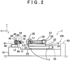
- FIGS. 1 and 2 illustrate an overall configuration of a grinding machine 1.
- the grinding machine 1 is configured such that relative movement of the grinding wheel 32 with respect to the workpiece W in the X-axis direction and the Z-axis direction is controlled so as to grind the workpiece W.
- a Z-axis direction slide table 12 is installed on a generally center portion of a platform 10 formed in a rectangular shape in a plan view.
- the Z-axis direction slide table 12 is guided by a pair of Z-axis direction guide rails 11 extending in the Z-axis direction to slide.
- the Z-axis direction slide table 12 is slid in the Z-axis direction by rotational motion of a Z-axis direction feed screw 13 driven by a Z-axis direction driving motor 14 (which corresponds to the Z-axis direction movement device).
- the Z-axis direction driving motor 14 is controlled by a control device 80 (such as an NC control device).
- the Z-axis direction driving motor 14 is provided with a Z-axis direction position detector 15 (which corresponds to the Z-axis relative movement amount detector) such as a rotary encoder that detects the rotational angle of an output shaft of the Z-axis direction driving motor 14 and sends a detection signal to the control device in order to check the position of the Z-axis direction slide table 12 in the Z-axis direction.
- the control device 80 relatively moves the grinding wheel 32 with respect to a truer 77 in the Z-axis direction using the Z-axis direction driving motor 14, and can detect the amount of relative movement of the grinding wheel 32 with respect to the truer 77 in the Z-axis direction on the basis of the detection signal from the Z-axis direction position detector 15.
- An X-axis direction slide table (grinding wheel slide table) 22 is installed on the Z-axis direction slide table 12.
- the X-axis direction slide table 22 is guided by a pair of X-axis direction guide rails 21 extending in the X-axis direction to slide.
- the X-axis direction slide table 22 is slid in the X-axis direction by rotational motion of an X-axis direction feed screw 23 driven by an X-axis direction driving motor 24 (which corresponds to the X-axis direction movement device).
- the X-axis direction driving motor 24 is controlled by the control device 80.
- the X-axis direction driving motor 24 is provided with an X-axis direction position detector 25 (which corresponds to the X-axis relative movement amount detector) such as a rotary encoder that detects the rotational angle of an output shaft of the X-axis direction driving motor 24 and sends a detection signal to the control device in order to check the position of the X-axis direction slide table 22 in the X-axis direction.
- an X-axis direction position detector 25 (which corresponds to the X-axis relative movement amount detector) such as a rotary encoder that detects the rotational angle of an output shaft of the X-axis direction driving motor 24 and sends a detection signal to the control device in order to check the position of the X-axis direction slide table 22 in the X-axis direction.
- the control device 80 relatively moves the grinding wheel 32 with respect to the truer 77 in the X-axis direction using the X-axis direction driving motor 24, and can detect the amount of relative movement of the grinding wheel 32 with respect to the truer 77 in the X-axis direction on the basis of the detection signal from the X-axis direction position detector 25.
- a grinding wheel driving motor 26 and a wheel spindle holder 30 are installed on the X-axis direction slide table 22.
- a driving pulley 27 is provided on an output shaft of the grinding wheel driving motor 26.
- a wheel spindle 31 is rotatably supported by the wheel spindle holder 30 to rotate about the grinding wheel rotational axis L1 which is parallel to the Z-axis direction.
- a grinding wheel 32 in a generally cylindrical shape is attached to a first end portion of the wheel spindle 31.
- a driven pulley 28 is provided at a second end portion of the wheel spindle 31.
- a belt 29 is stretched between the driving pulley 27 and the driven pulley 28. This allows torque of the output shaft of the grinding wheel driving motor 26 to be transferred to the wheel spindle 31 via the belt 29.
- a first main spindle device 40 and a second main spindle device 50 that hold a workpiece W in a shaft shape are installed on the platform 10 and on the workpiece rotational axis L2.
- the first main spindle device 40 and the second main spindle device 50 hold the workpiece W in position while rotating the workpiece W about the workpiece rotational axis L2 which is parallel to the Z axis.
- the first main spindle device 40 includes a headstock 41 fixed on the platform 10, a main spindle housing 42 that is reciprocally movable with respect to the headstock 41 in the direction of the workpiece rotational axis L2, and a main spindle 43 supported in the main spindle housing 42 so as to be rotatable about the workpiece rotational axis L2.
- a center member 44 is provided at the distal end of the main spindle 43 to support the center portion of one end surface of the workpiece W.
- the main spindle 43 is driven by a main spindle motor (not illustrated) controlled by the control device 80, and controlled so as to rotate to a desired angle at a desired angular velocity.
- the second main spindle device 50 also includes a headstock 51, a main spindle housing 52, a main spindle 53, and a center member 54.
- the main spindle housing 42 is provided with a truing device 60 including the truer 77 supported so as to be rotatable about the truer rotational axis L3.
- the grinding wheel rotational axis L1, the workpiece rotational axis L2, and the truer rotational axis L3 are all on a virtual plane VM which is parallel to the X-axis direction and the Z-axis direction.
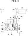
- the truing device 60 includes base members 65 and 66, a movable stage 70, an X-axis direction elastic support mechanism 62, a Z-axis direction slide body 74, a Z-axis direction elastic support mechanism 73, a truing spindle holder 75, a truing spindle 76, a truer 77, a linear motion guide 93, a movement restriction device 94, an X-axis elastic movement amount detector 95, and so forth.
- the base members 65 and 66 are fixed to the main spindle housing 42 of the first main spindle device 40.
- the linear motion guide 93 is attached to a surface of the movable stage 70 that faces the base member 66.
- the movable stage 70 is reciprocally slidable in the X-axis direction along a guide rail 66A provided on the base member 66.
- the movable stage 70 includes a base portion 71 that extends in the Z-axis direction and the Y-axis direction, and both side wall portions 72 that project in the X-axis direction from both end portions of the base portion 71 in the Z-axis direction.
- the base portion 71 and the both side wall portions 72 are formed in a substantially U shape.
- the movable stage 70 further includes bulged portions 72a bulged from the both side wall portions 72.
- the movable stage 70 is elastically supported by the X-axis direction elastic support mechanism 62 having an elastic member 64 so as to be movable in the X-axis direction with respect to the base member 65.
- Elastic movement refers to movement of a part of an elastic support mechanism accompanied by elastic deformation of an elastic member incorporated in the elastic support mechanism.
- the movement restriction device 94 that controls prohibition and permission of elastic movement of the movable stage 70 in at least the X-axis direction is provided between the guide rail 66A and the movable stage 70.
- the movement restriction device 94 may be a brake device, and the control device 80 may output a control signal to the movement restriction device 94 to control the movement restriction device 94 to a prohibited state (brake engaged state) and a permitted state (brake disengaged state).
- the Z-axis direction slide body 74 is elastically supported by the Z-axis direction elastic support mechanism 73 having a Z-axis direction return spring 90 so as to be elastically movable in the Z-axis direction with respect to the movable stage 70.
- the truing spindle holder 75 which houses the truing spindle 76 supported so as to be rotatable about the truer rotational axis L3 or the truing spindle 76 driven by a motor or the like to rotate about the truer rotational axis L3 is attached to the Z-axis direction slide body 74.
- the truer 77 (which corresponds to the truing device according to the present invention) of a generally cylindrical shape which perform truing of a surface of the grinding wheel 32 is attached to one end portion of the truing spindle 76.
- a truing surface 77a is formed on the outer periphery of the truer 77.
- the truing surface 77a is formed to have a recessed curved surface with an circular arc profile when seen in section including the axis.
- the truing surface 77a grinds the surface of the grinding wheel 32.
- the X-axis elastic movement amount detector 95 is installed between the movable stage 70 and the base member 65 to detect the amount of elastic movement of the movable stage 70 in the X-axis direction.
- the truer 77 and the grinding wheel 32 are spaced from each other in the X-axis direction.
- the distance to the movable stage 70 in the X-axis direction detected by the X-axis elastic movement amount detector 95 is a distance D1.
- FIGS. 5 and 6 illustrate a state in which the grinding wheel 32 pushes the truer 77 with a force F1 to elastically move the movable stage 70 in the X-axis direction.
- the distance to the movable stage 70 in the X-axis direction detected by the X-axis elastic movement amount detector 95 is a distance D2 (distance D1 > distance D2).
- the control device 80 can calculate the amount of elastic movement of the movable stage 70 in the X-axis direction as the distance D1 minus the distance D2 on the basis of the detection signal from the X-axis elastic movement amount detector 95.
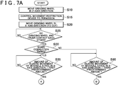
- the control device executes the process illustrated in FIG. 7 in the case where execution of truing is commanded, in the case where a truing timing set in advance has come, or the like.
- step S10 the control device starts driving rotation of the grinding wheel 32, and thereafter moves the grinding wheel 32 in the Z-axis direction.
- the process proceeds to step S15.
- the grinding wheel 32 is moved in the Z-axis direction by controlling the Z-axis direction driving motor, while the position of the grinding wheel 32 in the Z-axis direction is checked that is based on the detection signal from the Z-axis direction position detector 15, such that the position of the surface to be processed of the grinding wheel 32 in the Z-axis direction and the position of the truing surface 77a of the truer 77 in the Z-axis direction coincide with each other, that is, such that a portion of the surface to be processed of the grinding wheel with the largest diameter faces a portion of the truing surface with the smallest diameter in the X-axis direction.
- the truer 77 is also elastically supported in the Z-axis direction. Thus, there may be some deviation between the position of the surface to be processed of the grinding wheel 32 in the Z-axis direction and the position of the truing surface 77a of the truer 77 in the Z-axis direction. Therefore, there is no need for a Z-axis direction detection pin such as that according to the related art, and even if there is some error in position of the grinding wheel 32 in the Z-axis direction due to thermal displacement, such an error can be absorbed through elastic movement of the truer 77 in the Z-axis direction.
- step S15 the control device outputs a control signal to the movement restriction device to control the movement restriction device to a permitted state (in which elastic movement of the movable stage 70 in the X-axis direction is permitted).
- step S20 the control device controls the X-axis direction driving motor so as to gradually move the grinding wheel 32 toward the truer 77 in the X-axis direction (in the cutting direction) while checking the position of the grinding wheel 32 in the X-axis direction based on the detection signal from the X-axis direction position detector 25.
- step S25 the control device determines whether or not the grinding wheel 32 (the surface to be processed of the grinding wheel 32) and the truer 77 contact each other.
- the process proceeds to step S30. Otherwise, the process returns to step S25.
- the control device can detect whether or not the grinding wheel 32 (the surface to be processed of the grinding wheel 32) and the truer 77 contact each other in the X-axis direction on the basis of the detection signal from the X-axis elastic movement amount detector 95, for example.
- step (a) the grinding wheel contact step
- the control device relatively moves the grinding wheel with respect to the truer in the Z-axis direction to cause the truing device and the grinding wheel to face each other in the X-axis direction, controls the movement restriction device to the permitted state, and relatively moves the grinding wheel with respect to the truer in the X-axis direction to cause the surface to be processed of the grinding wheel to contact the truer.
- the control device determines whether or not the current truing is based on a grinding wheel shape correction timing. In the case where it is determined that the current truing is based on the shape correction timing (Yes), the process proceeds to step S35. Otherwise (No) (that is, in the case where the current truing is based on a surface roughness correction timing), the process proceeds to step S80.
- the surface roughness correction timing and the shape correction timing may be set such that surface roughness correction is started each time a first predetermined number of workpieces W are processed, and such that shape correction is performed each time a second predetermined number of workpieces W are processed (second predetermined number > first predetermined number). Only shape correction may be performed in the case where the shape correction timing and the surface roughness correction timing coincide with each other.
- the control device determines on the basis of the detection signal from the X-axis elastic movement amount detector 95 whether or not the amount of elastic movement of the truer 77 in the X-axis direction (the amount of elastic movement calculated as the distance D1 minus the distance D2 using the distance D1 indicated in FIG. 4 and the distance D2 indicated in FIG. 6 ) is equal to or more than a first predetermined amount. In the case where the elastic movement amount is equal to or more than the first predetermined amount (Yes), the process proceeds to step S40. Otherwise (No), the process returns to step S35.
- step S40 the control device stops movement of the grinding wheel 32 in the X-axis direction (cutting in the X-axis direction in step S20), and outputs a control signal to the movement restriction device to control the movement restriction device to the prohibited state (in which elastic movement of the movable stage 70 in the X-axis direction is prohibited).
- step S45 the control device stops movement of the grinding wheel 32 in the X-axis direction (cutting in the X-axis direction in step S20), and outputs a control signal to the movement restriction device to control the movement restriction device to the prohibited state (in which elastic movement of the movable stage 70 in the X-axis direction is prohibited).
- step S45 the control device controls the X-axis direction driving motor so as to further move the grinding wheel 32 toward the truer 77 (cause the grinding wheel 32 to cut into the truer 77) in the X-axis direction by a second predetermined amount to shape (refine the shape of) the grinding wheel 32 while checking the position of the grinding wheel 32 in the X-axis direction based on the detection signal from the X-axis direction position detector 25.
- the process proceeds to step S50.
- steps S35 to S45 correspond to step (b) (the grinding wheel shape correction step), in which when the grinding wheel and the truer contact each other (in the case where the first predetermined amount is substantially zero), or when the grinding wheel relatively cuts into the truing device in the X-axis direction until the amount of elastic movement of the truer in the X-axis direction reaches the first predetermined amount after the grinding wheel and the truer contact each other, the control device controls the movement restriction device to the prohibited state so as to prohibit elastic movement of the truer in at least the X-axis direction, and thereafter the grinding wheel is caused to further relatively cut into the truer in the X-axis direction by the second predetermined amount to correct the shape of the grinding wheel.
- step (b) the grinding wheel shape correction step
- step S50 the control device measures the time elapsed since step S50 started to determine whether or not a predetermined time has elapsed. In the case where the predetermined time has elapsed (Yes), the process proceeds to step S55. Otherwise (No), the process returns to step S50.
- the control device controls the X-axis direction driving motor so as to move the grinding wheel 32 to the side opposite to the truer 77 to space the grinding wheel 32 and the truer 77 from each other in the X-axis direction while checking the position of the grinding wheel 32 in the X-axis direction based on the detection signal from the X-axis direction position detector 25. The truing process is ended.
- the control device determines on the basis of the detection signal from the X-axis elastic movement amount detector whether or not the amount of elastic movement of the truer 77 in the X-axis direction (the amount of elastic movement calculated as the distance D1 minus the distance D2 using the distance D1 indicated in FIG. 4 and the distance D2 indicated in FIG. 6 ) is equal to or more than a third predetermined amount.
- the elastic movement amount is equal to or more than the third predetermined amount (Yes)
- the process proceeds to step S50. Otherwise (No), the process returns to step S80.
- the third predetermined amount is larger than the first predetermined amount.
- Step S80 corresponds to the grinding wheel surface roughness correction step, in which in the case where it is determined that the truing is based on the surface roughness correction timing (that is, it is determined that the truing is not based on the shape correction timing), the surface roughness of the grinding wheel is corrected by causing the grinding wheel to relatively cut into the truer in the X-axis direction until the amount of elastic movement of the truer in the X-axis direction after contact between the grinding wheel and the truer reaches the third predetermined amount which is larger than the first predetermined amount.
- the processes in steps S50 and S55 have already been described, and thus are not described here.
- FIG. 8 illustrates operation in the grinding wheel shape correction step (operation executed in steps S25, S30, S35, S40, and S45) and operation in the grinding wheel surface roughness correction step (operation executed in steps S25, S30, and S80) in the case where the first predetermined amount is not zero in step S35.
- FIG. 9 illustrates operation in the grinding wheel shape correction step (operation executed in steps S25, S30, S35, S40, and S45) and operation in the grinding wheel surface roughness correction step (operation executed in steps S25, S30, and S80) in the case where the first predetermined amount is substantially zero in step S35.
- the first predetermined amount, the second predetermined amount, and the third predetermined amount are depicted as significantly exaggerated compared to the actual values (e.g. several micrometers to several hundreds of micrometers).
- the grinding wheel 32 cuts into the truer 77, which is prohibited from making elastic movement in the X-axis direction, by the second predetermined amount to execute truing of itself.
- the grinding wheel 32 has run-out (an error in peripheral shape from a perfect circle shape)
- run-out can be appropriately eliminated and the grinding wheel 32 can be reshaped into a perfect circle shape.
- the grinding wheel 32 cuts into the truer 77 in the X-axis direction until the truer 77, which is permitted to make elastic movement in the X-axis direction, is elastically moved by the third predetermined amount, to execute truing of itself.
- the surface of the grinding wheel 32 can be ground by an appropriate thickness to dress the grinding wheel and unnecessarily grinding of the surface of the grinding wheel 32 can be avoided.
- the life of the grinding wheel can be extended.
- the provision of the movement restriction device eliminates the need to separately provide a truer that is elastically movable in the X-axis direction and a truer that is not elastically movable in the X-axis direction.
- the grinding machine can be made simpler and more compact in configuration, and truing can be completed in a short time compared to a case where separate truers are provided.
- the truer 77 is also elastically movable in the Z-axis direction. Thus, it is convenient that the truer 77 is automatically and elastically moved to a correct position in the Z-axis direction even if there is some deviation in position of the grinding wheel 32 with respect to the truer 77 in the Z-axis direction.
- the grinding wheel is moved with respect to the truer in the X-axis direction and the Z-axis direction.
- the truer may be relatively moved with respect to the grinding wheel in the X-axis direction and the Z-axis direction.
- the movement restriction device controls permission and prohibition of elastic movement of the truer in the X-axis direction.
- the movement restriction device may control permission and prohibition of elastic movement of the truer in the X-axis direction and the Z-axis direction. That is, the movement restriction device may control permission and prohibition of elastic movement of the truer in at least the X-axis direction.
Landscapes
- Engineering & Computer Science (AREA)
- Mechanical Engineering (AREA)
- Grinding-Machine Dressing And Accessory Apparatuses (AREA)
- Constituent Portions Of Griding Lathes, Driving, Sensing And Control (AREA)
- Grinding Of Cylindrical And Plane Surfaces (AREA)
Claims (3)
- Schleifscheibenabrichteverfahren, wobei
das Schleifscheibenabrichteverfahren unter Verwendung von Folgendem durchgeführt wird:einer Schleifscheibe (32), die eine allgemein zylindrische Form aufweist und angetrieben ist, um sich um eine Schleifscheibendrehachse (L1) zu drehen;einem Abrichtegerät (77), das so gelagert ist, dass es um eine Abrichterdrehachse (L3) drehbar ist, die parallel zu einer Z-Achsenrichtung liegt, die parallel zu der Schleifscheibendrehachse (L1) liegt, oder so gelagert ist, dass es angetrieben wird, um sich um die Abrichterdrehachse (L3) zu drehen, um ein Abrichten der Schleifscheibe (32) auszuführen; undeinem Steuergerät (80), das die Schleifscheibe (32) mit Bezug auf das Abrichtegerät (77) relativ in der X-Achsenrichtung und der Z-Achsenrichtung bewegt, wobei die X-Achsenrichtung eine Richtung ist, die rechtwinklig zu der Schleifscheibendrehachse (L1) liegt, und in der die Schleifscheibe (32) in das Abrichtegerät (77) einschneidet,das Abrichtegerät (77) elastisch in der Z-Achsenrichtung gelagert ist, um in der Z-Achsenrichtung elastisch beweglich zu sein, in der X-Achsenrichtung elastisch gelagert ist, um in der X-Achsenrichtung elastisch beweglich zu sein, und ein Bewegungsbeschränkungsgerät (94) hat, das eine Verhinderung und eine Gestattung einer elastischen Bewegung in zumindest der X-Achsenrichtung steuert,
wobei das Schleifscheibenabrichteverfahren umfasst:einen Berührungsschritt, in dem das Steuergerät (80) bewirkt, dass eine Oberfläche der Schleifscheibe (32) das Abrichtegerät (77) durch Bewegen der Schleifscheibe (32) mit Bezug auf das Abrichtegerät (77) in eine Z-Achsenrichtung berührt, um zu verursachen, dass das Abrichtegerät (77) und die Schleifscheibe (32) in einer X-Achsenrichtung zueinander gerichtet sind, und dann das Bewegungsbeschränkungsgerät (94) zu einem gestatteten Zustand steuert, um die Schleifscheibe (32) mit Bezug auf das Abrichtegerät (77) relativ in die X-Achsenrichtung zu bewegen; undeinen Formkorrekturschritt, in dem das Steuergerät (80) eine Form der Schleifscheibe (32) korrigiert, wenn die Schleifscheibe (32) und das Abrichtegerät (77) einander berühren, oder wenn die Schleifscheibe (32) relativ in das Abrichtegerät (77) in der X-Achsenrichtung einschneidet, bis eine Größe einer elastischen Bewegung des Abrichtegeräts (77) in einer X-Achsenrichtung eine erste vorbestimmte Größe erreicht, nachdem die Schleifscheibe (32) und das Abrichtegerät (77) einander berührt haben, das Bewegungsbeschränkungsgerät (94) zu einem verhinderten Zustand steuert, um eine elastische Bewegung des Abrichtegeräts (77) in zumindest der X-Achsenrichtung zu verhindern, und danach verursacht, dass die Schleifscheibe (32) weiter relativ um eine zweite vorbestimmte Größe in der X-Achsenrichtung in das Abrichtegerät (77) einschneidet. - Schleifscheibenabrichteverfahren nach Anspruch 1, wobei:nach dem Berührungsschritt und vor dem Formkorrekturschritt das Steuergerät (80) ausgehend von einem vorbestimmten Bestimmungszustand bestimmt, ob das vorliegende Abrichten auf einer Formkorrekturzeit zum Korrigieren der Form der Schleifscheibe (32) basiert oder auf einer Oberflächenrauigkeitskorrekturzeit zum Korrigieren einer Oberflächenrauigkeit der Schleifscheibe (32) basiert;in dem Fall, in dem bestimmt ist, dass das aktuelle Abrichten auf der Formkorrekturzeit basiert, der Formkorrekturschritt ausgeführt wird; undin dem Fall, in dem bestimmt ist, dass das aktuelle Abrichten auf der Oberflächenrauigkeitskorrekturzeit basiert, die Oberflächenrauigkeit der Schleifscheibe durch Durchführen eines Oberflächenrauigkeitskorrekturschritts korrigiert wird, in dem das Steuergerät (80) verursacht, dass die Schleifscheibe (32) in der X-Achsenrichtung relativ in das Abrichtegerät (77) einschneidet, bis die Größe der elastischen Bewegung des Abrichtegeräts (77) in der X-Achsenrichtung nach der Berührung zwischen der Schleifscheibe (32) und dem Abrichtegerät (77) eine dritte vorbestimmte Größe erreicht, die größer als die erste vorbestimmte Größe ist.
- Schleifmaschine (1), die ein Abrichten einer Schleifscheibe (32) durch das Schleifscheibenabrichteverfahren nach Anspruch 1 oder 2 ausführt, mit:einer Schleifscheibe (32) die eine allgemein zylindrische Form aufweist und angetrieben ist, um sich um eine Schleifscheibendrehachse (L1) zu drehen;einem Abrichtegerät (77), das so gelagert ist, dass es um eine Abrichterdrehachse (L3) drehbar ist, die parallel zu einer Z-Achsenrichtung liegt, die parallel zu der Schleifscheibendrehrichtung (L1) liegt, oder so gelagert ist, dass es angetrieben ist, um die Abrichterdrehachse (L3) zu drehen, um ein Abrichten der Schleifscheibe (32) auszuführen; undeinem Steuergerät (80), das die Schleifscheibe (32) mit Bezug auf das Abrichtegerät (77) relativ in der X-Achsenrichtung und der Z-Achsenrichtung bewegt, wobei die X-Achsenrichtung eine Richtung ist, die rechtwinklig zu der Schleifscheibendrehachse (L1) liegt, und in der die Schleifscheibe (32) in das Abrichtegerät (77) einschneidet,das Abrichtegerät (77) elastisch in der Z-Achsenrichtung gelagert ist, um elastisch in der Z-Achsenrichtung beweglich zu sein, in der X-Achsenrichtung elastisch gelagert ist, um in der X-Achsenrichtung elastisch beweglich zu sein, und ein Bewegungsbeschränkungsgerät (94) hat, das eine Verhinderung und eine Gestattung einer elastischen Bewegung in zumindest der X-Achsenrichtung steuert,
ein X-Achsenrichtungsbewegungsgerät (24), das die Schleifscheibe (32) mit Bezug auf das Abrichtegerät (77) in der X-Achsenrichtung relativ bewegt;
einen X-Achsen-Relativbewegungsgrößenerfasser (25), der in der Lage ist, eine Größe einer relativen Bewegung der Schleifscheibe (32) mit Bezug auf das Abrichtegerät (77) in der X-Achsenrichtung zu erfassen, das durch das X-Achsenrichtungsbewegungsgerät (24) verursacht ist;
ein Z-Achsenrichtungsbewegungsgerät (14), das die Schleifscheibe (32) mit Bezug auf das Abrichtegerät (77) in der Z-Achsenrichtung relativ bewegt;
einen Z-Achsen-Relativbewegungsgrößenerfasser (15), der in der Lage ist, eine Größe einer relativen Bewegung der Schleifscheibe (32) mit Bezug auf das Abrichtegerät (77) in der Z-Achsenrichtung zu erfassen, die durch das Z-Achsenrichtungsbewegungsgerät (14) verursacht ist;
einen X-Achsen-Elastischen-Bewegungsgrößenerfasser (95), der in der Lage ist, eine Größe einer elastischen Bewegung des Abrichtegeräts (77) in der X-Achsenrichtung zu erfassen;
dem Bewegungsbeschränkungsgerät (94), das die Verhinderung und Gestattung der elastischen Bewegung des Abrichtegeräts (77) in zumindest der X-Achsenrichtung steuert; und
dem Steuergerät (80), das Erfassungssignale von dem X-Achsen-Relativbewegungsgrößenerfasser (25), dem Z-Achsen-Relativ-Bewegungsgrößenerfasser (15) und dem X-Achsen-Elastischen-Bewegungsgrößenerfasser (95) empfängt, um das X-Achsenrichtungsbewegungsgerät (24), das Z-Achsenrichtungsbewegungsgerät (14) und das Bewegungsbeschränkungsgerät (94) zu steuern.
Applications Claiming Priority (1)
| Application Number | Priority Date | Filing Date | Title |
|---|---|---|---|
| JP2014052927A JP6252270B2 (ja) | 2014-03-17 | 2014-03-17 | 研削盤の砥石のツルーイング方法及び研削盤 |
Publications (2)
| Publication Number | Publication Date |
|---|---|
| EP2921259A1 EP2921259A1 (de) | 2015-09-23 |
| EP2921259B1 true EP2921259B1 (de) | 2016-12-07 |
Family
ID=52669526
Family Applications (1)
| Application Number | Title | Priority Date | Filing Date |
|---|---|---|---|
| EP15158986.8A Not-in-force EP2921259B1 (de) | 2014-03-17 | 2015-03-13 | Schleifscheibenabrichtverfahren und schleifmaschine |
Country Status (4)
| Country | Link |
|---|---|
| US (1) | US9446499B2 (de) |
| EP (1) | EP2921259B1 (de) |
| JP (1) | JP6252270B2 (de) |
| CN (1) | CN104924217B (de) |
Families Citing this family (9)
| Publication number | Priority date | Publication date | Assignee | Title |
|---|---|---|---|---|
| EP3159104A1 (de) * | 2015-10-21 | 2017-04-26 | ThyssenKrupp Metalúrgica Campo Limpo Ltda. | Vorrichtung zum abrichten einer schleifscheibe |
| CN106002633B (zh) * | 2016-05-24 | 2018-10-23 | 东北大学 | 一种陶瓷结合剂cbn砂轮的复合修整方法 |
| CN107263297A (zh) * | 2017-07-31 | 2017-10-20 | 浙江洁宇环保装备科技有限公司 | 一种除尘风管外壁抛光机 |
| CN107414613A (zh) * | 2017-07-31 | 2017-12-01 | 浙江洁宇环保装备科技有限公司 | 一种除尘风管抛光方法 |
| CN109968205B (zh) * | 2019-05-10 | 2020-08-14 | 滨州鲁德曲轴有限责任公司 | 一种可调节的曲轴轴颈沉割的砂轮修整器 |
| CN110270929B (zh) * | 2019-07-18 | 2020-09-08 | 郑州磨料磨具磨削研究所有限公司 | 一种超硬砂轮实用修整方法 |
| CN110524423A (zh) * | 2019-09-27 | 2019-12-03 | 精海联科(宁波)智能设备有限公司 | 一种圆弧砂轮修磨装置 |
| CN112247846B (zh) * | 2020-10-21 | 2022-09-27 | 黑格智能科技(嘉兴)有限公司 | 全自动数控砂轮修整机及全自动数控砂轮修整方法 |
| CN113547622B (zh) * | 2021-07-14 | 2022-06-14 | 江西陶瓷工艺美术职业技术学院 | 一种陶瓷加工用的坯体批量化修边装置 |
Family Cites Families (15)
| Publication number | Priority date | Publication date | Assignee | Title |
|---|---|---|---|---|
| US1995304A (en) * | 1932-04-21 | 1935-03-26 | United Shoe Machinery Corp | Device for dressing grinding wheels |
| GB519081A (en) | 1938-09-21 | 1940-03-15 | Coventry Gauge & Tool Co Ltd | Improved method of forming the operative surface of grinding or abrading wheels |
| US4073281A (en) * | 1975-09-29 | 1978-02-14 | Toyoda-Koki Kabushiki-Kaisha | Truing and dressing apparatus for grinding wheels |
| JPS5834255B2 (ja) * | 1976-09-17 | 1983-07-26 | 豊田工機株式会社 | 砥石車のドレツシング装置 |
| DE3826251A1 (de) * | 1987-08-03 | 1989-02-16 | Yamazaki Mazak Corp | Werkzeugmaschine mit einer schleiffunktion, umfassend eine elektroerosionsaus-/zurichtvorrichtung und ein schleifwerkzeug |
| DE3889655D1 (de) * | 1987-12-23 | 1994-06-23 | Fortuna Werke Maschf Ag | Verfahren zum abrichten einer schleifscheibe. |
| JPH05269665A (ja) * | 1992-03-24 | 1993-10-19 | Toyoda Mach Works Ltd | 砥石修正装置 |
| US5595528A (en) * | 1994-10-19 | 1997-01-21 | Vermont Rebuild, Inc. | Grinding wheel dresser |
| US6783428B1 (en) * | 1999-01-18 | 2004-08-31 | Nsk Ltd. | Method for forming grooves on workpiece and for dressing a grindstone used in the groove formation |
| JP2001138234A (ja) * | 1999-11-19 | 2001-05-22 | Nsk Ltd | 総型砥石形状の成形方法 |
| JP2007260809A (ja) * | 2006-03-28 | 2007-10-11 | Jtekt Corp | 砥石車のツルーイング方法および装置 |
| US7797074B2 (en) * | 2007-03-01 | 2010-09-14 | Mori Seiki Usa, Inc. | Machine including grinding wheel and wheel dresser |
| JP2009285776A (ja) * | 2008-05-29 | 2009-12-10 | Jtekt Corp | 研削装置 |
| JP5857660B2 (ja) * | 2011-06-27 | 2016-02-10 | 株式会社ジェイテクト | 研削盤のツルーイング装置 |
| US9254549B2 (en) | 2013-05-07 | 2016-02-09 | Jtekt Corporation | Grinding machine |
-
2014
- 2014-03-17 JP JP2014052927A patent/JP6252270B2/ja not_active Expired - Fee Related
-
2015
- 2015-03-10 CN CN201510104699.0A patent/CN104924217B/zh not_active Expired - Fee Related
- 2015-03-13 US US14/657,392 patent/US9446499B2/en not_active Expired - Fee Related
- 2015-03-13 EP EP15158986.8A patent/EP2921259B1/de not_active Not-in-force
Also Published As
| Publication number | Publication date |
|---|---|
| CN104924217A (zh) | 2015-09-23 |
| US9446499B2 (en) | 2016-09-20 |
| JP6252270B2 (ja) | 2017-12-27 |
| JP2015174188A (ja) | 2015-10-05 |
| CN104924217B (zh) | 2018-10-12 |
| EP2921259A1 (de) | 2015-09-23 |
| US20150258659A1 (en) | 2015-09-17 |
Similar Documents
| Publication | Publication Date | Title |
|---|---|---|
| EP2921259B1 (de) | Schleifscheibenabrichtverfahren und schleifmaschine | |
| EP2540443B1 (de) | Abrichtvorrichtung einer Schleifmaschine | |
| US8601703B2 (en) | Workpiece centering apparatus and workpiece centering method | |
| US20100105289A1 (en) | Grinding machine and grinding method | |
| US8900034B2 (en) | Machine tool and machining method | |
| EP1941970B1 (de) | Verfahren und Vorrichtung zur Ausführung der automatischen Zentrierung eines ringförmigen Werkstücks auf einer drehenden Oberfläche | |
| JP6101115B2 (ja) | 工作機械及び、工作機械によるワークの加工方法 | |
| US6732009B2 (en) | Machining error correction method adapted for numerically controlled machine tool and grinding machine using the same | |
| EP4015141B1 (de) | Zentrierwerkzeug, zentriervorrichtung, werkzeugmaschine, verfahren zum zentrieren eines kreisförmigen werkstücks, herstellungsverfahren für ein kreisförmiges werkstück, herstellungsverfahren für ein ringförmiges element, verfahren zur herstellung einer maschine, verfahren zur herstellung eines fahrzeugs und programm | |
| US9050703B2 (en) | Grinding machine and grinding method | |
| JP2010194623A (ja) | ねじ研削盤及びねじ溝研削方法 | |
| KR20170094248A (ko) | 중심 공작물 영역을 지지 및 측정하기 위한 측정 스테디 레스트, 이 측정 스테디 레스트를 갖는 연삭기, 및 중심 공작물 영역을 지지 및 측정하기 위한 방법 | |
| EP2801441B1 (de) | Schleifmaschine | |
| JP6102480B2 (ja) | 研削盤および研削方法 | |
| CN113561061A (zh) | 修整装置 | |
| KR102050766B1 (ko) | 성형 연삭 장치 | |
| JP7417281B2 (ja) | センタレス研削盤 | |
| JP6135287B2 (ja) | 研削盤 | |
| JP2024063416A (ja) | 溝研削方法、溝研削装置及びプログラム | |
| JP2017127926A (ja) | 砥石修正装置、及び同装置を備えた工作機械、並びに砥石修正方法 | |
| JP6135288B2 (ja) | 研削盤 | |
| JP2005088167A (ja) | 研削加工方法および研削加工装置 | |
| JP2017127925A (ja) | ホーニング加工機 | |
| JPH11198035A (ja) | 研削装置 | |
| LT et al. | 415 50 Göteborg (SE) |
Legal Events
| Date | Code | Title | Description |
|---|---|---|---|
| PUAI | Public reference made under article 153(3) epc to a published international application that has entered the european phase |
Free format text: ORIGINAL CODE: 0009012 |
|
| AK | Designated contracting states |
Kind code of ref document: A1 Designated state(s): AL AT BE BG CH CY CZ DE DK EE ES FI FR GB GR HR HU IE IS IT LI LT LU LV MC MK MT NL NO PL PT RO RS SE SI SK SM TR |
|
| AX | Request for extension of the european patent |
Extension state: BA ME |
|
| 17P | Request for examination filed |
Effective date: 20151117 |
|
| GRAP | Despatch of communication of intention to grant a patent |
Free format text: ORIGINAL CODE: EPIDOSNIGR1 |
|
| INTG | Intention to grant announced |
Effective date: 20160621 |
|
| GRAS | Grant fee paid |
Free format text: ORIGINAL CODE: EPIDOSNIGR3 |
|
| GRAA | (expected) grant |
Free format text: ORIGINAL CODE: 0009210 |
|
| AK | Designated contracting states |
Kind code of ref document: B1 Designated state(s): AL AT BE BG CH CY CZ DE DK EE ES FI FR GB GR HR HU IE IS IT LI LT LU LV MC MK MT NL NO PL PT RO RS SE SI SK SM TR |
|
| REG | Reference to a national code |
Ref country code: GB Ref legal event code: FG4D |
|
| REG | Reference to a national code |
Ref country code: CH Ref legal event code: EP Ref country code: AT Ref legal event code: REF Ref document number: 851301 Country of ref document: AT Kind code of ref document: T Effective date: 20161215 |
|
| REG | Reference to a national code |
Ref country code: IE Ref legal event code: FG4D |
|
| REG | Reference to a national code |
Ref country code: DE Ref legal event code: R096 Ref document number: 602015000889 Country of ref document: DE |
|
| PG25 | Lapsed in a contracting state [announced via postgrant information from national office to epo] |
Ref country code: LV Free format text: LAPSE BECAUSE OF FAILURE TO SUBMIT A TRANSLATION OF THE DESCRIPTION OR TO PAY THE FEE WITHIN THE PRESCRIBED TIME-LIMIT Effective date: 20161207 |
|
| REG | Reference to a national code |
Ref country code: LT Ref legal event code: MG4D |
|
| REG | Reference to a national code |
Ref country code: NL Ref legal event code: MP Effective date: 20161207 |
|
| PG25 | Lapsed in a contracting state [announced via postgrant information from national office to epo] |
Ref country code: LT Free format text: LAPSE BECAUSE OF FAILURE TO SUBMIT A TRANSLATION OF THE DESCRIPTION OR TO PAY THE FEE WITHIN THE PRESCRIBED TIME-LIMIT Effective date: 20161207 Ref country code: SE Free format text: LAPSE BECAUSE OF FAILURE TO SUBMIT A TRANSLATION OF THE DESCRIPTION OR TO PAY THE FEE WITHIN THE PRESCRIBED TIME-LIMIT Effective date: 20161207 Ref country code: GR Free format text: LAPSE BECAUSE OF FAILURE TO SUBMIT A TRANSLATION OF THE DESCRIPTION OR TO PAY THE FEE WITHIN THE PRESCRIBED TIME-LIMIT Effective date: 20170308 Ref country code: NO Free format text: LAPSE BECAUSE OF FAILURE TO SUBMIT A TRANSLATION OF THE DESCRIPTION OR TO PAY THE FEE WITHIN THE PRESCRIBED TIME-LIMIT Effective date: 20170307 |
|
| REG | Reference to a national code |
Ref country code: AT Ref legal event code: MK05 Ref document number: 851301 Country of ref document: AT Kind code of ref document: T Effective date: 20161207 |
|
| PG25 | Lapsed in a contracting state [announced via postgrant information from national office to epo] |
Ref country code: RS Free format text: LAPSE BECAUSE OF FAILURE TO SUBMIT A TRANSLATION OF THE DESCRIPTION OR TO PAY THE FEE WITHIN THE PRESCRIBED TIME-LIMIT Effective date: 20161207 Ref country code: HR Free format text: LAPSE BECAUSE OF FAILURE TO SUBMIT A TRANSLATION OF THE DESCRIPTION OR TO PAY THE FEE WITHIN THE PRESCRIBED TIME-LIMIT Effective date: 20161207 Ref country code: FI Free format text: LAPSE BECAUSE OF FAILURE TO SUBMIT A TRANSLATION OF THE DESCRIPTION OR TO PAY THE FEE WITHIN THE PRESCRIBED TIME-LIMIT Effective date: 20161207 Ref country code: ES Free format text: LAPSE BECAUSE OF FAILURE TO SUBMIT A TRANSLATION OF THE DESCRIPTION OR TO PAY THE FEE WITHIN THE PRESCRIBED TIME-LIMIT Effective date: 20161207 |
|
| PG25 | Lapsed in a contracting state [announced via postgrant information from national office to epo] |
Ref country code: NL Free format text: LAPSE BECAUSE OF FAILURE TO SUBMIT A TRANSLATION OF THE DESCRIPTION OR TO PAY THE FEE WITHIN THE PRESCRIBED TIME-LIMIT Effective date: 20161207 |
|
| PG25 | Lapsed in a contracting state [announced via postgrant information from national office to epo] |
Ref country code: RO Free format text: LAPSE BECAUSE OF FAILURE TO SUBMIT A TRANSLATION OF THE DESCRIPTION OR TO PAY THE FEE WITHIN THE PRESCRIBED TIME-LIMIT Effective date: 20161207 Ref country code: EE Free format text: LAPSE BECAUSE OF FAILURE TO SUBMIT A TRANSLATION OF THE DESCRIPTION OR TO PAY THE FEE WITHIN THE PRESCRIBED TIME-LIMIT Effective date: 20161207 Ref country code: CZ Free format text: LAPSE BECAUSE OF FAILURE TO SUBMIT A TRANSLATION OF THE DESCRIPTION OR TO PAY THE FEE WITHIN THE PRESCRIBED TIME-LIMIT Effective date: 20161207 Ref country code: IS Free format text: LAPSE BECAUSE OF FAILURE TO SUBMIT A TRANSLATION OF THE DESCRIPTION OR TO PAY THE FEE WITHIN THE PRESCRIBED TIME-LIMIT Effective date: 20170407 Ref country code: SK Free format text: LAPSE BECAUSE OF FAILURE TO SUBMIT A TRANSLATION OF THE DESCRIPTION OR TO PAY THE FEE WITHIN THE PRESCRIBED TIME-LIMIT Effective date: 20161207 |
|
| PG25 | Lapsed in a contracting state [announced via postgrant information from national office to epo] |
Ref country code: PL Free format text: LAPSE BECAUSE OF FAILURE TO SUBMIT A TRANSLATION OF THE DESCRIPTION OR TO PAY THE FEE WITHIN THE PRESCRIBED TIME-LIMIT Effective date: 20161207 Ref country code: BE Free format text: LAPSE BECAUSE OF FAILURE TO SUBMIT A TRANSLATION OF THE DESCRIPTION OR TO PAY THE FEE WITHIN THE PRESCRIBED TIME-LIMIT Effective date: 20161207 Ref country code: PT Free format text: LAPSE BECAUSE OF FAILURE TO SUBMIT A TRANSLATION OF THE DESCRIPTION OR TO PAY THE FEE WITHIN THE PRESCRIBED TIME-LIMIT Effective date: 20170407 Ref country code: AT Free format text: LAPSE BECAUSE OF FAILURE TO SUBMIT A TRANSLATION OF THE DESCRIPTION OR TO PAY THE FEE WITHIN THE PRESCRIBED TIME-LIMIT Effective date: 20161207 Ref country code: SM Free format text: LAPSE BECAUSE OF FAILURE TO SUBMIT A TRANSLATION OF THE DESCRIPTION OR TO PAY THE FEE WITHIN THE PRESCRIBED TIME-LIMIT Effective date: 20161207 Ref country code: IT Free format text: LAPSE BECAUSE OF FAILURE TO SUBMIT A TRANSLATION OF THE DESCRIPTION OR TO PAY THE FEE WITHIN THE PRESCRIBED TIME-LIMIT Effective date: 20161207 Ref country code: BG Free format text: LAPSE BECAUSE OF FAILURE TO SUBMIT A TRANSLATION OF THE DESCRIPTION OR TO PAY THE FEE WITHIN THE PRESCRIBED TIME-LIMIT Effective date: 20170307 |
|
| REG | Reference to a national code |
Ref country code: DE Ref legal event code: R097 Ref document number: 602015000889 Country of ref document: DE |
|
| PLBE | No opposition filed within time limit |
Free format text: ORIGINAL CODE: 0009261 |
|
| STAA | Information on the status of an ep patent application or granted ep patent |
Free format text: STATUS: NO OPPOSITION FILED WITHIN TIME LIMIT |
|
| 26N | No opposition filed |
Effective date: 20170908 |
|
| PG25 | Lapsed in a contracting state [announced via postgrant information from national office to epo] |
Ref country code: MC Free format text: LAPSE BECAUSE OF FAILURE TO SUBMIT A TRANSLATION OF THE DESCRIPTION OR TO PAY THE FEE WITHIN THE PRESCRIBED TIME-LIMIT Effective date: 20161207 Ref country code: DK Free format text: LAPSE BECAUSE OF FAILURE TO SUBMIT A TRANSLATION OF THE DESCRIPTION OR TO PAY THE FEE WITHIN THE PRESCRIBED TIME-LIMIT Effective date: 20161207 Ref country code: SI Free format text: LAPSE BECAUSE OF FAILURE TO SUBMIT A TRANSLATION OF THE DESCRIPTION OR TO PAY THE FEE WITHIN THE PRESCRIBED TIME-LIMIT Effective date: 20161207 |
|
| REG | Reference to a national code |
Ref country code: IE Ref legal event code: MM4A |
|
| REG | Reference to a national code |
Ref country code: FR Ref legal event code: ST Effective date: 20171130 |
|
| PG25 | Lapsed in a contracting state [announced via postgrant information from national office to epo] |
Ref country code: LU Free format text: LAPSE BECAUSE OF NON-PAYMENT OF DUE FEES Effective date: 20170313 Ref country code: FR Free format text: LAPSE BECAUSE OF NON-PAYMENT OF DUE FEES Effective date: 20170331 |
|
| PG25 | Lapsed in a contracting state [announced via postgrant information from national office to epo] |
Ref country code: IE Free format text: LAPSE BECAUSE OF NON-PAYMENT OF DUE FEES Effective date: 20170313 |
|
| PG25 | Lapsed in a contracting state [announced via postgrant information from national office to epo] |
Ref country code: MT Free format text: LAPSE BECAUSE OF NON-PAYMENT OF DUE FEES Effective date: 20170313 |
|
| REG | Reference to a national code |
Ref country code: CH Ref legal event code: PL |
|
| PG25 | Lapsed in a contracting state [announced via postgrant information from national office to epo] |
Ref country code: LI Free format text: LAPSE BECAUSE OF NON-PAYMENT OF DUE FEES Effective date: 20180331 Ref country code: CH Free format text: LAPSE BECAUSE OF NON-PAYMENT OF DUE FEES Effective date: 20180331 |
|
| PG25 | Lapsed in a contracting state [announced via postgrant information from national office to epo] |
Ref country code: HU Free format text: LAPSE BECAUSE OF FAILURE TO SUBMIT A TRANSLATION OF THE DESCRIPTION OR TO PAY THE FEE WITHIN THE PRESCRIBED TIME-LIMIT; INVALID AB INITIO Effective date: 20150313 |
|
| PG25 | Lapsed in a contracting state [announced via postgrant information from national office to epo] |
Ref country code: CY Free format text: LAPSE BECAUSE OF FAILURE TO SUBMIT A TRANSLATION OF THE DESCRIPTION OR TO PAY THE FEE WITHIN THE PRESCRIBED TIME-LIMIT Effective date: 20161207 |
|
| GBPC | Gb: european patent ceased through non-payment of renewal fee |
Effective date: 20190313 |
|
| PG25 | Lapsed in a contracting state [announced via postgrant information from national office to epo] |
Ref country code: MK Free format text: LAPSE BECAUSE OF FAILURE TO SUBMIT A TRANSLATION OF THE DESCRIPTION OR TO PAY THE FEE WITHIN THE PRESCRIBED TIME-LIMIT Effective date: 20161207 |
|
| PG25 | Lapsed in a contracting state [announced via postgrant information from national office to epo] |
Ref country code: GB Free format text: LAPSE BECAUSE OF NON-PAYMENT OF DUE FEES Effective date: 20190313 |
|
| PG25 | Lapsed in a contracting state [announced via postgrant information from national office to epo] |
Ref country code: TR Free format text: LAPSE BECAUSE OF FAILURE TO SUBMIT A TRANSLATION OF THE DESCRIPTION OR TO PAY THE FEE WITHIN THE PRESCRIBED TIME-LIMIT Effective date: 20161207 |
|
| PG25 | Lapsed in a contracting state [announced via postgrant information from national office to epo] |
Ref country code: AL Free format text: LAPSE BECAUSE OF FAILURE TO SUBMIT A TRANSLATION OF THE DESCRIPTION OR TO PAY THE FEE WITHIN THE PRESCRIBED TIME-LIMIT Effective date: 20161207 |
|
| PGFP | Annual fee paid to national office [announced via postgrant information from national office to epo] |
Ref country code: DE Payment date: 20220203 Year of fee payment: 8 |
|
| REG | Reference to a national code |
Ref country code: DE Ref legal event code: R119 Ref document number: 602015000889 Country of ref document: DE |
|
| PG25 | Lapsed in a contracting state [announced via postgrant information from national office to epo] |
Ref country code: DE Free format text: LAPSE BECAUSE OF NON-PAYMENT OF DUE FEES Effective date: 20231003 |