EP2921260A1 - Appareil à entraînement pneumatique - Google Patents
Appareil à entraînement pneumatique Download PDFInfo
- Publication number
- EP2921260A1 EP2921260A1 EP14160861.2A EP14160861A EP2921260A1 EP 2921260 A1 EP2921260 A1 EP 2921260A1 EP 14160861 A EP14160861 A EP 14160861A EP 2921260 A1 EP2921260 A1 EP 2921260A1
- Authority
- EP
- European Patent Office
- Prior art keywords
- piston rod
- arm
- head housing
- tool according
- bearing element
- Prior art date
- Legal status (The legal status is an assumption and is not a legal conclusion. Google has not performed a legal analysis and makes no representation as to the accuracy of the status listed.)
- Granted
Links
Images








Classifications
-
- B—PERFORMING OPERATIONS; TRANSPORTING
- B25—HAND TOOLS; PORTABLE POWER-DRIVEN TOOLS; MANIPULATORS
- B25B—TOOLS OR BENCH DEVICES NOT OTHERWISE PROVIDED FOR, FOR FASTENING, CONNECTING, DISENGAGING, OR HOLDING
- B25B5/00—Clamps
- B25B5/06—Arrangements for positively actuating jaws
- B25B5/12—Arrangements for positively actuating jaws using toggle links
- B25B5/122—Arrangements for positively actuating jaws using toggle links with fluid drive
-
- B—PERFORMING OPERATIONS; TRANSPORTING
- B25—HAND TOOLS; PORTABLE POWER-DRIVEN TOOLS; MANIPULATORS
- B25B—TOOLS OR BENCH DEVICES NOT OTHERWISE PROVIDED FOR, FOR FASTENING, CONNECTING, DISENGAGING, OR HOLDING
- B25B5/00—Clamps
- B25B5/06—Arrangements for positively actuating jaws
- B25B5/061—Arrangements for positively actuating jaws with fluid drive
- B25B5/064—Arrangements for positively actuating jaws with fluid drive with clamping means pivoting around an axis perpendicular to the pressing direction
Definitions
- the invention relates to a pneumatically operable working device, in particular for use in the bodywork of the motor vehicle industry, with a cylinder having a cylinder housing, a displaceable in this piston and a connected thereto, linearly displaceable and led out of the cylinder housing, not variable-length piston rod, and with a connected to the cylinder housing head housing, wherein a projecting into the head housing portion of the piston rod with at least one toggle lever for pivoting a toggle associated arm, in particular gripping arm or clamping arm cooperates, said arm in the head housing stored and pivotable between a closed position and an open position.
- Such a working device is from the DE 296 15 157 U1 known.
- this two toggle lever pivotally engage directly on the located in the head housing end of the piston rod.
- two gripping arms between a closed position and an open position are pivotable. In the closed position, the gripping arms are arranged parallel to each other.
- a arranged in the region of the free end of the piston rod bearing axis for the two toggle lever is provided at the end with bearing rollers, which are guided in guide grooves of the head housing.
- Pneumatically operated equipment having gripping or clamping arms, and in which a non-variable-length piston rod is used, are further from the DE 10 2004 040 606 B3 .
- a pneumatically operable working device in which a piston of a cylinder is positioned in the open position of a clamping arm in the region of a bottom of the cylinder housing.
- the piston rod is designed variable in length and has piston rod parts with threaded portions, wherein the piston rod parts are screwed together.
- Object of the present invention is to develop a working device of the type mentioned so that this, with structurally simple design, with respect to the open position of the arm is infinitely adjustable.
- the open position of the arm in particular of the gripping arm or clamping arm, is infinitely adjustable.
- the piston rod has a threaded portion and receives in the region of the threaded portion an adjustable in the longitudinal direction of the piston rod stop member.
- the stop member is in the open position of this arm to a stationary relative to the head housing system.
- the piston rod is rotatable with respect to its longitudinal axis. It takes in the region of the knee lever end facing a bearing element for the toggle.
- the piston rod is rotatable with respect to this bearing element.
- the stop member can be changed in its position relative to the piston rod, based on the axial direction of the piston rod, whereby by adjusting the abutment portion of the opening angle of the arm is infinitely adjustable. At this opening angle, the stop member contacts the station relative to the head housing stationary.
- the working device may be designed such that the cylinder and the head housing constitute separate structural units or a common structural unit.
- the stop member is in particular rotationally fixed in the head housing positioned. If the piston rod is rotated with respect to its longitudinal axis, and thus changes the position of the stop member in the direction of the longitudinal axis of the piston rod to this, therefore, the stop member is not rotated and displaced only in the axial direction of the piston rod.
- This positioning of the stop member in the head housing can be achieved in different ways, for example by a guide of the stop member in the direction of the longitudinal axis of the piston rod in the head housing, or by a non-circular design of the stop member, wherein the non-circular outer contour of the stop member cooperates with a correspondingly shaped inner contour of the head housing.
- the relative to the head housing stationary system can be designed in different ways.
- the stationary system has the task to form the bearing surface for the stop member, which prevents further contact with the abutment member on the stationary system further axial displacement of the stop member and thus defines the open position of the arm.
- the contact surface extends orthogonal to the longitudinal axis of the piston rod.
- a contact surface of the abutment part extending orthogonally to the longitudinal axis of the piston rod interacts with the abutment surface upon contact of the abutment part.
- a head housing facing away from the bottom of the cylinder housing means for axially displacing the piston rod in the closed position of the arm with arranged in the region of the bottom piston in order to move out the toggle lever from an over-center position.
- This means for axially displacing the piston rod in the closed position of the arm is provided so as to allow, in the closed position of the arm, the supply of fluid to the cylinder to allow fluid-independent release of the arm from the over-center position of the toggle lever. To achieve this, it is only necessary to exert a force on the piston rod via the means for axial displacement of the piston rod, whereby the piston rod is moved slightly axially and the toggle lever is pivoted from the over-center position.
- the pivot angle of the toggle lever from the dead center position in the Mattertot Vietnamese ein the fraction of a degree of angle, so that it is only necessary to move the toggle lever from the Kochtot Vietnamese simply to move the piston rod by means of the axial displacement of the piston rod by a small distance, which corresponds to this small angle.
- the means for axial displacement of the piston rod have the means for rotating the piston rod.
- the means are in the simplest manner as in the bottom of the cylinder housing slidably and sealed to the bottom of the plunger formed, which has a receptacle for a tool for rotating the plunger outside of the cylinder housing and within the cylinder housing a receptacle for rotationally fixed engagement in a receptacle of this facing the end of the piston rod.
- the pneumatically operated implement has, in particular, a toggle lever for pivoting an arm associated therewith, or in particular two toggle levers, wherein each of the two toggle levers serves to pivot an arm associated with this toggle lever.
- the arm is in particular a gripping arm.
- the toggle lever or the toggle lever are arranged in the closed position of the arm or the arms, in particular in an over-center position.
- a further pivoting of the respective toggle lever on the Kochtot Vietnamese too much is prevented by a stop, which can be arranged arbitrarily and has the task to prevent axial displacement of the piston rod or with this piston rod cooperating components in the direction of the bottom of the cylinder housing.
- the bearing element has on opposite sides receptacles for the pivotable mounting of two hinge connectors which are pivotally connected in the region of the bearing element facing away from the ends with the two arms at a distance from the pivot axes of the arms, wherein the pivot axes the joint connector and the arms are arranged parallel to each other.
- the receptacles are thus provided for the pivotable mounting of the two joint connectors.
- the same bearing element can be used for reasons of standardization of the implement, in which case only one articulated connector is connected to the bearing element, for connection to one arm, while the other receptacle of the bearing element does not receive a hinge connector.
- the bearing element accommodates the two joint connectors, it is considered to be particularly advantageous if the bearing element, the joint connectors and the arms are arranged symmetrically with respect to a plane passing through the longitudinal axis of the piston rod. This results in a symmetrical design of the implement in the region of the head housing and the two arms, which introduced into the two arms gripping or clamping forces when contacting the working device associated component, such as a body panel, are symmetrically introduced into the implement.
- the bearing element is guided in a guide of the head housing in the direction of the longitudinal axis of the piston rod.
- This guide is important not only under the aspect of the actual leadership of the bearing element in the head housing, but also under the aspect of the introduction of the forces acting on the arm or the arms, from the bearing element in the head housing.
- This guided bearing of the bearing element makes it possible to carry out the implement both in the variant with one arm and in the variant with two arms. In the variant with one arm forces are introduced unbalanced over the arm in the head housing. This is due to the leadership of the bearing element in the head housing readily possible, because the forces are introduced directly through the bearing element and the guide associated therewith in the head housing.
- bearing element is mounted by means of a sliding and / or roller bearing in a guide of the head housing.
- rolling bearing the use of rolling bearings in the form of roller or spherical bearings is considered advantageous.
- the guide has in particular mutually parallel guide surfaces, which are arranged parallel to the pivot axis of the arm.
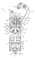
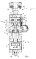
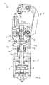
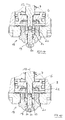
- the figures show a pneumatically operable implement 1, which is used in particular in the bodywork of the automotive industry.
- the implement 1 is as a handling gripper with a single arm 2 - gripper arm - according to the embodiment of the Fig. 1 to 7 - or with two arms 2 - two Gripping arms - according to the embodiment of the Fig. 7 to 13 educated. Both embodiments have a similar structure. In this respect, the presentation of the Fig. 1 to 4 the first embodiment described.
- the working device 1 has a cylinder 3.
- a head housing 5 is connected via not illustrated fastening means.
- the cylinder housing 4 receives a displaceable in this piston 6 and a connected thereto, linearly displaceable and sealed out of the cylinder housing 4 brought out, not variable-length piston rod 7.
- An area of the piston rod 7 projecting into the head housing 5 cooperates with at least one toggle lever 8 for pivoting the arm 2 associated therewith.
- This arm 2 is mounted in the head housing 5 via an axis 9 and about this axis 9 between an open position ( Fig. 1 ) and a closed position ( Fig. 3 ) pivotable.
- the open position of the arm 2 is infinitely adjustable.
- the piston rod 7 has a threaded portion 10 and receives in the region thereof an adjustable in the longitudinal direction of the piston rod 7 stop member 11.
- the stop member 11 is in the open position of the arm 2 to a stationary relative to the cylinder housing 4 system, which is formed as an annular contact surface 12 of the head housing 5, which surrounds the piston rod 7 and is arranged orthogonal to the longitudinal axis 13 of the piston rod 7.
- the cooperating with the contact surface 12 of the head housing 5, also annular contact surface of the stop member 14 is designated by the reference numeral 14. This contact surface 14 is arranged parallel to the contact surface 12.
- the stop member 11 is rotatably positioned in the head housing 5, specifically via a not-shown groove which extends parallel to the longitudinal axis 13 of the piston rod 7 and in which the stop member 11 engages.
- the thread in the Area of the threaded portion 10 between the piston rod 7 and stop member 11 is self-locking.
- the piston rod 7 is rotatable with respect to its longitudinal axis 13 and receives in the region of the knee lever 8 end facing a bearing element 15 for the toggle lever 8.
- the piston rod 7 is rotatable about the longitudinal axis 13 with respect to the bearing element 15.
- the piston rod 7 is inserted into a receptacle 16 of the bearing element 15 and connected by means of a form-locking ring 17 in the extension of the longitudinal axis 13 fixed to the bearing element 15.
- a rotation of the piston rod 7 about the longitudinal axis 13 with respect to the receptacle 16 and thus of the bearing element 15 is possible.
- a head housing 5 facing away from the bottom 18 of the cylinder housing 4 has means 19 for rotating the piston rod 7 in the closed position ( Fig. 3 ) of the arm 2 at in the region of the bottom 18 arranged piston 6.
- This means 19 is a plunger which is mounted sealed in the bottom 18 and slidable in the longitudinal axis 13 of the piston rod 7.
- the arranged outside of the cylinder housing 4 end of the plunger 19 has a hexagonal recess 20 for receiving a tool, not shown, for rotating the plunger 19 about the longitudinal axis 13, wherein the tool is inserted with a hexagonal end in the hexagonal recess 20.
- the arranged within the cylinder housing 4 end is provided with a projection 21 with hexagonal cross-section.
- Fig. 14 shows the engagement of the plunger 19, wherein the projection 21 is inserted in the closed position of the arm 2 in a hexagonal recess in cross section 22 of the facing end of the piston rod 7.
- the bearing member 15 is formed symmetrically with respect to a plane passing through the longitudinal axis 13 of the piston rod 7.
- two axes 25 are mounted, wherein the respective axis 25 on both sides of the bearing element 15 roller-shaped rolling bearing elements 26 receives, which are guided in a bearing groove 27 extending in the longitudinal axis.
- the bearing element 15 is guided substantially without play in the direction of the longitudinal axis 13.
- the bearing element 15 has tabs 28 formed as tabs.
- Each tab 28 is intended to receive a plate-shaped hinge connector 29 in the region of an axis 30. In the embodiment having only one arm 2, only one tab 28 is tied while the other tab 28 remains free. This other tab is connected only in the event that a second arm 2 is present.
- the hinge connector 29 is pivotally connected to the arm 2 in the region of the end facing away from the bearing element 15 in the region of an axis 31.
- This axis 31 is positioned at a distance from the axis 9 of the arm 2.
- the axis 9 and the axes 30 and 31 are arranged parallel to each other.
- the axes 9, 30 and 31 are constructed so that the axes 30 and 31 and 9 and 31 form the toggle lever 8, wherein in the open position according to Fig. 1 the connecting line between the axes 30 and 31 occupies an angle of less than 90 ° with respect to the line connecting the axes 9 and 31 with respect to their centers, while in the closed position of the arm according to Figs Fig.
- this angle is slightly greater than 90 °, so that there is a slight over-center position, in which the bearing element 15 is fixed in the direction of the longitudinal axis 15 and in the direction of the piston rod 7 by the piston rod side roller bearing elements 26 in the region of the end of the Storage groove 27, which faces the piston rod, abut at this end 32 of the bearing groove 27.
- Fig. 15 shows a detail of the mounting of the joint connector 29 in the arm 2.
- the axis 31 is extended and engages in a substantially over a quarter circle extending guide groove 33 of the head housing 5 a.
- the cylinder housing 4 is divided by the piston 5 into two working spaces 34 and 35 of the fluid.
- the working space 34 is acted upon in a known manner with fluid so that the piston 6 is moved in the direction of the bottom 18.
- the stop member 11 reaches in the region of the contact surface 14 out of contact with the contact surface 12 of the head housing 5.
- the piston 6 and the piston rod 7 pull the bearing member 15 and it is about the toggle lever 8 of the arm 2 with its in the region of the free end of the Armes 2 arranged gripping element 36 moves in the direction of a mounted in the head housing 5 gripping member 37.
- the intermediate position is in Fig. 2 illustrated.
- this over-center position of the toggle lever 8 can be released by the above-described mechanical loading of the plunger 19.
- the axial displacement of the piston rod 7 and thus the corresponding axial displacement of the bearing element 15 is achieved, that the hinge connector 29 is slightly pivoted, so that the center of the axis 30 is further away from the ground than the center of the axis 31. In this position, a pivoting of the arm 2 mechanically possible by the arm 2 is gripped.
- the position of the stop member 11 can be changed by turning the piston rod 7.
- the plunger 19 is inserted into the recess 22 of the piston rod 7.
- the plunger 19 is moved back when pressure is applied to the cylinder 3 to transfer the piston 6 from the closed position of the working device, wherein pressure medium is supplied to the working space 35 and also acts on the facing end face of the plunger 19.
- pressure medium is supplied to the working space 35 and also acts on the facing end face of the plunger 19.
- Fig. 4 is denoted by the reference numeral 38 an interrogation device which is mounted in the head housing 5 and the interrogation of the position of the bearing member 15 and the stop member 11 is used.
- the Fig. 5 to 7 show for the previously discussed operating conditions according to the Fig. 1 to 4 a with respect to the opening angle adjusted working device 1 with an opening angle of 50 °.
- This adjustment is evident, for example, in that the contact surfaces 12 and 14 have a different distance from each other when the arm 2 is closed, the change in the distance corresponding to the change in the position of the abutment part 11 relative to the piston rod 7.
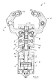
- the embodiment according to the Fig. 8 to 13 corresponds largely to that of Fig. 1 to 7 , To avoid repetition, reference is made to the detailed description of the first embodiment.
- two arms 2 are provided instead of an arm.
- the connection of the second arm is identical to the one arm according to the first embodiment, whereby the bearing element 15, the hinge connector 29 and the arms 2 are arranged symmetrically to the plane passing through the longitudinal axis 13 of the piston rod 7 level. In this respect, reference is made to the above description, concerning the connection of one arm 2.
- the second embodiment also differs from the first embodiment in that the respective arm 2 is modified and, moreover, the gripping element 37 is part of the second arm 2.
- Fig. 8 shows the implement 1 with the two arms 2 in an open position of 90 °
- Fig. 9 the intermediate position
- Fig. 10 the closed position in which contact the two gripping elements 36 and 37.
- Fig. 11 shows for the execution of the implement 1 with the two arms 2 an adjusted position of the stop member 11, so that an open position of 160 ° according to Fig. 11 reveals Fig. 12 the intermediate position is illustrated and Fig. 13 the closed position shows.
- the two embodiments illustrate that can be converted to the variant with an arm 2 or two arms 2 by simply retooling or supplementing the implement 1. It is only necessary, starting from the variant with the one arm 2 to use a modified head housing 5, which has no receptacle for the gripping member 37 and instead to store in this modified head housing 5, the two arms 2 on the knee lever 8 and to the To connect bearing element 15.
Landscapes
- Engineering & Computer Science (AREA)
- Mechanical Engineering (AREA)
- Jigs For Machine Tools (AREA)
- Manipulator (AREA)
Priority Applications (4)
| Application Number | Priority Date | Filing Date | Title |
|---|---|---|---|
| EP14160861.2A EP2921260B1 (fr) | 2014-03-20 | 2014-03-20 | Appareil à entraînement pneumatique |
| EP14164124.1A EP2921261B2 (fr) | 2014-03-20 | 2014-04-10 | Appareil à entraînement pneumatique |
| PCT/EP2015/055901 WO2015140288A1 (fr) | 2014-03-20 | 2015-03-20 | Engin de travail à fonctionnement pneumatique |
| US14/907,700 US10016878B2 (en) | 2014-03-20 | 2015-03-20 | Pneumatically operable work tool |
Applications Claiming Priority (1)
| Application Number | Priority Date | Filing Date | Title |
|---|---|---|---|
| EP14160861.2A EP2921260B1 (fr) | 2014-03-20 | 2014-03-20 | Appareil à entraînement pneumatique |
Publications (2)
| Publication Number | Publication Date |
|---|---|
| EP2921260A1 true EP2921260A1 (fr) | 2015-09-23 |
| EP2921260B1 EP2921260B1 (fr) | 2016-08-31 |
Family
ID=50336159
Family Applications (2)
| Application Number | Title | Priority Date | Filing Date |
|---|---|---|---|
| EP14160861.2A Not-in-force EP2921260B1 (fr) | 2014-03-20 | 2014-03-20 | Appareil à entraînement pneumatique |
| EP14164124.1A Not-in-force EP2921261B2 (fr) | 2014-03-20 | 2014-04-10 | Appareil à entraînement pneumatique |
Family Applications After (1)
| Application Number | Title | Priority Date | Filing Date |
|---|---|---|---|
| EP14164124.1A Not-in-force EP2921261B2 (fr) | 2014-03-20 | 2014-04-10 | Appareil à entraînement pneumatique |
Country Status (3)
| Country | Link |
|---|---|
| US (1) | US10016878B2 (fr) |
| EP (2) | EP2921260B1 (fr) |
| WO (1) | WO2015140288A1 (fr) |
Cited By (1)
| Publication number | Priority date | Publication date | Assignee | Title |
|---|---|---|---|---|
| CN112916817A (zh) * | 2019-12-06 | 2021-06-08 | 汉达精密电子(昆山)有限公司 | 压铸件抓取装置 |
Families Citing this family (3)
| Publication number | Priority date | Publication date | Assignee | Title |
|---|---|---|---|---|
| US10786886B2 (en) * | 2016-11-01 | 2020-09-29 | Dominion Technologies Group, Inc. | Pneumatic crankshaft clamp assembly |
| KR102032416B1 (ko) * | 2019-02-25 | 2019-10-15 | 김용구 | 내열형 에어 클램프 장치 |
| CN113500540A (zh) * | 2021-07-28 | 2021-10-15 | 沭阳鑫洪锐金属制品有限公司 | 一种连接紧固件 |
Citations (6)
| Publication number | Priority date | Publication date | Assignee | Title |
|---|---|---|---|---|
| DE29615157U1 (de) | 1996-01-09 | 1996-11-07 | Tünkers Maschinenbau GmbH, 40880 Ratingen | Kniehebelspann- und Greifvorrichtung |
| EP1336452A1 (fr) * | 2002-02-13 | 2003-08-20 | Kabushiki Kaisha Kosmek | Dispositif de contrôle de l'opération d'une outil de serrage |
| DE102004040606B3 (de) | 2004-08-21 | 2006-01-12 | Tünkers Maschinenbau Gmbh | Als Gripper ausgebildete Kniehebelspannvorrichtung, insbesondere zur Verwendung im Karosseriebau der Kfz-Industrie |
| USRE41223E1 (en) | 1998-01-07 | 2010-04-13 | Norgren Automotive, Inc. | Clamp with improved internal cam action |
| EP2241402A1 (fr) | 2009-04-16 | 2010-10-20 | VEP Automation S.r.l. | Dispositif de verrouillage de pièces |
| EP2548700A1 (fr) | 2011-07-20 | 2013-01-23 | UNIVER S.p.A. | Outil pneumatique |
Family Cites Families (23)
| Publication number | Priority date | Publication date | Assignee | Title |
|---|---|---|---|---|
| GB709285A (en) * | 1951-08-09 | 1954-05-19 | James Arthur Holt | Improvements in clamps and other gripping devices |
| US3027155A (en) * | 1958-12-23 | 1962-03-27 | Transfer Tools Ltd | Means for releasably clamping articles |
| US3347542A (en) * | 1965-04-19 | 1967-10-17 | Seizer Power Clamp Inc | Toggle clamp |
| DE3130942A1 (de) * | 1981-08-05 | 1983-04-28 | Tünkers Maschinenbau GmbH, 4030 Ratingen | Druckmittelbetaetigbare kniehebelspannvorrichtung mit elastischem federgelenk und loesbar befestigtem spannarm |
| US4458889A (en) * | 1982-09-29 | 1984-07-10 | Dover Corporation (De-Sta-Co. Div.) | Locking power clamp |
| US4494739A (en) * | 1983-03-04 | 1985-01-22 | State Die & Engineering, Inc. | Power operated rotatable clamping assembly |
| US4529182A (en) * | 1983-04-11 | 1985-07-16 | State Die & Engineering, Inc. | Wide opening gripping jaw assembly |
| US4620696A (en) * | 1983-08-10 | 1986-11-04 | Blatt Leland F | Power clamp |
| US4576367A (en) * | 1985-01-02 | 1986-03-18 | Aladdin Engineering & Mfg. Co. | Pneumatic mechanical clamp including locking means |
| FR2630953B1 (fr) * | 1988-05-06 | 1991-04-05 | Genus Int | Dispositif de bridage pour plaques ou profiles l'un contre l'autre |
| DE4238613A1 (de) * | 1992-11-16 | 1994-05-19 | Smw Schneider & Weishaupt Gmbh | Selbstzentrierende Lünette |
| US6056281A (en) * | 1997-10-03 | 2000-05-02 | Phd, Inc. | Adjustable stoppers and mounting assemblies for parts grippers |
| US5853211A (en) * | 1997-01-10 | 1998-12-29 | Btm Corporation | Universal gripper |
| JP3293802B2 (ja) * | 1999-07-07 | 2002-06-17 | エスエムシー株式会社 | 位置検出機能付きチャック |
| GB2359512B (en) * | 1999-11-26 | 2004-01-21 | Hmc Brauer Ltd | Power clamps |
| DE10013874B4 (de) † | 2000-03-21 | 2013-04-18 | De-Sta-Co Metallerzeugnisse Gmbh | Kniehebelspannvorrichtung mit Öffnungswinkelbegrenzung |
| DE20012710U1 (de) * | 2000-07-22 | 2000-11-23 | Röhm GmbH, 89567 Sontheim | Lünette |
| DE20018114U1 (de) † | 2000-10-23 | 2002-02-28 | DE-STA-CO Metallerzeugnisse GmbH, 61449 Steinbach | Elektrisch betätigbare Werkstück-Spannvorrichtung |
| EP1368161B1 (fr) * | 2001-03-16 | 2021-04-21 | PHD, Inc. | Prehenseur dote d'un ensemble de capteurs reglables |
| US6488273B2 (en) * | 2001-04-20 | 2002-12-03 | Btm Corporation | Powered pivot unit |
| DE10135280A1 (de) * | 2001-07-19 | 2003-02-06 | Rudolf Kohlert | Spannelement zum positionsflexiblen Spannen von Werkstücken |
| JP2004090163A (ja) * | 2002-08-30 | 2004-03-25 | Smc Corp | クランプ装置 |
| JP4789006B2 (ja) * | 2006-07-31 | 2011-10-05 | Smc株式会社 | クランプ装置 |
-
2014
- 2014-03-20 EP EP14160861.2A patent/EP2921260B1/fr not_active Not-in-force
- 2014-04-10 EP EP14164124.1A patent/EP2921261B2/fr not_active Not-in-force
-
2015
- 2015-03-20 WO PCT/EP2015/055901 patent/WO2015140288A1/fr not_active Ceased
- 2015-03-20 US US14/907,700 patent/US10016878B2/en active Active
Patent Citations (6)
| Publication number | Priority date | Publication date | Assignee | Title |
|---|---|---|---|---|
| DE29615157U1 (de) | 1996-01-09 | 1996-11-07 | Tünkers Maschinenbau GmbH, 40880 Ratingen | Kniehebelspann- und Greifvorrichtung |
| USRE41223E1 (en) | 1998-01-07 | 2010-04-13 | Norgren Automotive, Inc. | Clamp with improved internal cam action |
| EP1336452A1 (fr) * | 2002-02-13 | 2003-08-20 | Kabushiki Kaisha Kosmek | Dispositif de contrôle de l'opération d'une outil de serrage |
| DE102004040606B3 (de) | 2004-08-21 | 2006-01-12 | Tünkers Maschinenbau Gmbh | Als Gripper ausgebildete Kniehebelspannvorrichtung, insbesondere zur Verwendung im Karosseriebau der Kfz-Industrie |
| EP2241402A1 (fr) | 2009-04-16 | 2010-10-20 | VEP Automation S.r.l. | Dispositif de verrouillage de pièces |
| EP2548700A1 (fr) | 2011-07-20 | 2013-01-23 | UNIVER S.p.A. | Outil pneumatique |
Cited By (1)
| Publication number | Priority date | Publication date | Assignee | Title |
|---|---|---|---|---|
| CN112916817A (zh) * | 2019-12-06 | 2021-06-08 | 汉达精密电子(昆山)有限公司 | 压铸件抓取装置 |
Also Published As
| Publication number | Publication date |
|---|---|
| US20160167202A1 (en) | 2016-06-16 |
| EP2921261B2 (fr) | 2020-01-22 |
| EP2921261B1 (fr) | 2016-11-02 |
| EP2921261A1 (fr) | 2015-09-23 |
| EP2921260B1 (fr) | 2016-08-31 |
| US10016878B2 (en) | 2018-07-10 |
| WO2015140288A1 (fr) | 2015-09-24 |
Similar Documents
| Publication | Publication Date | Title |
|---|---|---|
| EP2763820B1 (fr) | Dispositif de préhension ou de serrage | |
| EP3012923B1 (fr) | Pince de pression | |
| DE2916312C2 (de) | Greifzange für Handhabungsgeräte | |
| EP0481275A1 (fr) | Dispositif de changement d'outil pour une machine-outil | |
| EP2873122A1 (fr) | Outil de sertissage d'embouts | |
| EP2921260B1 (fr) | Appareil à entraînement pneumatique | |
| DE202016008355U1 (de) | Betätigungsvorrichtung vom Gelenkhebel- oder Nockentyp zur genauen Positionierung eines schwenkbaren Arms | |
| DE102021000171B3 (de) | Kniehebelspannvorrichtung mit geradliniger Spannkraft und Spindelantrieb | |
| DE102007050353A1 (de) | Greifvorrichtung | |
| EP3370890B1 (fr) | Dispositif de réglage d'un cylindre de refoulement d'une cage refouleuse | |
| DE102018002358B4 (de) | Kniehebelspannvorrichtung, zur Verwendung im Karosseriebau der Kfz-Industrie mit zusätzlichem Widerlager am Kniehebelgelenkelement | |
| DE102011016666A1 (de) | Vorrichtung zum Betreiben eines Greif- oder Bewegungswerkzeugs durch einen elektrischen Stellantrieb | |
| DE3309513A1 (de) | Schraubstock | |
| DE102014005657C5 (de) | Anschlagmodul | |
| DE69301651T2 (de) | Spannkopf | |
| DE102011102905B3 (de) | Kniehebelspannvorrichtung, insbesondere für Karosserieteile der Kfz-Industrie | |
| EP3101304B1 (fr) | Frein à disque | |
| EP3050673A1 (fr) | Dispositif de tension | |
| DE102015119177B4 (de) | Spannvorrichtung und Verfahren zum Spannen eines Wekstücks | |
| DE2232709A1 (de) | Betaetigungs- oder kraftverstaerkungseinrichtung | |
| DE102005021460A1 (de) | Verstelleinrichtung für Kupplungen und Getriebebremsen, insbesondere von Kraftfahrzeugen zum Verstellen eines einen Auflage- und Drehpunkt eines gebogenen Hebels bildenden Auflagerelements | |
| DE102022117144B4 (de) | Zangenwerkzeug mit asymmetrischem Keil | |
| DE29815832U1 (de) | Vorrichtung zum lösbaren Einspannen eines Werkstücks | |
| EP2985216A1 (fr) | Actionneur commandé manuellement | |
| EP2218548B1 (fr) | Liaison articulée destinée à transformer un mouvement linéaire en mouvement oscillatoire et dispositif de serrage doté d'une telle liaison articulée |
Legal Events
| Date | Code | Title | Description |
|---|---|---|---|
| PUAI | Public reference made under article 153(3) epc to a published international application that has entered the european phase |
Free format text: ORIGINAL CODE: 0009012 |
|
| 17P | Request for examination filed |
Effective date: 20140918 |
|
| AK | Designated contracting states |
Kind code of ref document: A1 Designated state(s): AL AT BE BG CH CY CZ DE DK EE ES FI FR GB GR HR HU IE IS IT LI LT LU LV MC MK MT NL NO PL PT RO RS SE SI SK SM TR |
|
| AX | Request for extension of the european patent |
Extension state: BA ME |
|
| RIC1 | Information provided on ipc code assigned before grant |
Ipc: B25B 5/12 20060101ALI20151124BHEP Ipc: B25B 5/06 20060101AFI20151124BHEP |
|
| GRAP | Despatch of communication of intention to grant a patent |
Free format text: ORIGINAL CODE: EPIDOSNIGR1 |
|
| INTG | Intention to grant announced |
Effective date: 20160112 |
|
| GRAS | Grant fee paid |
Free format text: ORIGINAL CODE: EPIDOSNIGR3 |
|
| GRAP | Despatch of communication of intention to grant a patent |
Free format text: ORIGINAL CODE: EPIDOSNIGR1 |
|
| RIN1 | Information on inventor provided before grant (corrected) |
Inventor name: RAIMONDI, STEFANO |
|
| INTG | Intention to grant announced |
Effective date: 20160523 |
|
| GRAA | (expected) grant |
Free format text: ORIGINAL CODE: 0009210 |
|
| AK | Designated contracting states |
Kind code of ref document: B1 Designated state(s): AL AT BE BG CH CY CZ DE DK EE ES FI FR GB GR HR HU IE IS IT LI LT LU LV MC MK MT NL NO PL PT RO RS SE SI SK SM TR |
|
| REG | Reference to a national code |
Ref country code: CH Ref legal event code: EP Ref country code: GB Ref legal event code: FG4D Free format text: NOT ENGLISH |
|
| REG | Reference to a national code |
Ref country code: IE Ref legal event code: FG4D Free format text: LANGUAGE OF EP DOCUMENT: GERMAN |
|
| REG | Reference to a national code |
Ref country code: DE Ref legal event code: R096 Ref document number: 502014001334 Country of ref document: DE |
|
| REG | Reference to a national code |
Ref country code: AT Ref legal event code: REF Ref document number: 824579 Country of ref document: AT Kind code of ref document: T Effective date: 20161015 |
|
| REG | Reference to a national code |
Ref country code: LT Ref legal event code: MG4D |
|
| REG | Reference to a national code |
Ref country code: NL Ref legal event code: MP Effective date: 20160831 |
|
| PG25 | Lapsed in a contracting state [announced via postgrant information from national office to epo] |
Ref country code: LT Free format text: LAPSE BECAUSE OF FAILURE TO SUBMIT A TRANSLATION OF THE DESCRIPTION OR TO PAY THE FEE WITHIN THE PRESCRIBED TIME-LIMIT Effective date: 20160831 Ref country code: NO Free format text: LAPSE BECAUSE OF FAILURE TO SUBMIT A TRANSLATION OF THE DESCRIPTION OR TO PAY THE FEE WITHIN THE PRESCRIBED TIME-LIMIT Effective date: 20161130 Ref country code: RS Free format text: LAPSE BECAUSE OF FAILURE TO SUBMIT A TRANSLATION OF THE DESCRIPTION OR TO PAY THE FEE WITHIN THE PRESCRIBED TIME-LIMIT Effective date: 20160831 Ref country code: FI Free format text: LAPSE BECAUSE OF FAILURE TO SUBMIT A TRANSLATION OF THE DESCRIPTION OR TO PAY THE FEE WITHIN THE PRESCRIBED TIME-LIMIT Effective date: 20160831 Ref country code: HR Free format text: LAPSE BECAUSE OF FAILURE TO SUBMIT A TRANSLATION OF THE DESCRIPTION OR TO PAY THE FEE WITHIN THE PRESCRIBED TIME-LIMIT Effective date: 20160831 |
|
| PG25 | Lapsed in a contracting state [announced via postgrant information from national office to epo] |
Ref country code: LV Free format text: LAPSE BECAUSE OF FAILURE TO SUBMIT A TRANSLATION OF THE DESCRIPTION OR TO PAY THE FEE WITHIN THE PRESCRIBED TIME-LIMIT Effective date: 20160831 Ref country code: NL Free format text: LAPSE BECAUSE OF FAILURE TO SUBMIT A TRANSLATION OF THE DESCRIPTION OR TO PAY THE FEE WITHIN THE PRESCRIBED TIME-LIMIT Effective date: 20160831 Ref country code: GR Free format text: LAPSE BECAUSE OF FAILURE TO SUBMIT A TRANSLATION OF THE DESCRIPTION OR TO PAY THE FEE WITHIN THE PRESCRIBED TIME-LIMIT Effective date: 20161201 Ref country code: SE Free format text: LAPSE BECAUSE OF FAILURE TO SUBMIT A TRANSLATION OF THE DESCRIPTION OR TO PAY THE FEE WITHIN THE PRESCRIBED TIME-LIMIT Effective date: 20160831 Ref country code: ES Free format text: LAPSE BECAUSE OF FAILURE TO SUBMIT A TRANSLATION OF THE DESCRIPTION OR TO PAY THE FEE WITHIN THE PRESCRIBED TIME-LIMIT Effective date: 20160831 |
|
| REG | Reference to a national code |
Ref country code: FR Ref legal event code: PLFP Year of fee payment: 4 |
|
| PG25 | Lapsed in a contracting state [announced via postgrant information from national office to epo] |
Ref country code: EE Free format text: LAPSE BECAUSE OF FAILURE TO SUBMIT A TRANSLATION OF THE DESCRIPTION OR TO PAY THE FEE WITHIN THE PRESCRIBED TIME-LIMIT Effective date: 20160831 Ref country code: RO Free format text: LAPSE BECAUSE OF FAILURE TO SUBMIT A TRANSLATION OF THE DESCRIPTION OR TO PAY THE FEE WITHIN THE PRESCRIBED TIME-LIMIT Effective date: 20160831 |
|
| PGFP | Annual fee paid to national office [announced via postgrant information from national office to epo] |
Ref country code: FR Payment date: 20170322 Year of fee payment: 4 |
|
| PG25 | Lapsed in a contracting state [announced via postgrant information from national office to epo] |
Ref country code: PL Free format text: LAPSE BECAUSE OF FAILURE TO SUBMIT A TRANSLATION OF THE DESCRIPTION OR TO PAY THE FEE WITHIN THE PRESCRIBED TIME-LIMIT Effective date: 20160831 Ref country code: SK Free format text: LAPSE BECAUSE OF FAILURE TO SUBMIT A TRANSLATION OF THE DESCRIPTION OR TO PAY THE FEE WITHIN THE PRESCRIBED TIME-LIMIT Effective date: 20160831 Ref country code: SM Free format text: LAPSE BECAUSE OF FAILURE TO SUBMIT A TRANSLATION OF THE DESCRIPTION OR TO PAY THE FEE WITHIN THE PRESCRIBED TIME-LIMIT Effective date: 20160831 Ref country code: PT Free format text: LAPSE BECAUSE OF FAILURE TO SUBMIT A TRANSLATION OF THE DESCRIPTION OR TO PAY THE FEE WITHIN THE PRESCRIBED TIME-LIMIT Effective date: 20170102 Ref country code: BG Free format text: LAPSE BECAUSE OF FAILURE TO SUBMIT A TRANSLATION OF THE DESCRIPTION OR TO PAY THE FEE WITHIN THE PRESCRIBED TIME-LIMIT Effective date: 20161130 Ref country code: DK Free format text: LAPSE BECAUSE OF FAILURE TO SUBMIT A TRANSLATION OF THE DESCRIPTION OR TO PAY THE FEE WITHIN THE PRESCRIBED TIME-LIMIT Effective date: 20160831 Ref country code: CZ Free format text: LAPSE BECAUSE OF FAILURE TO SUBMIT A TRANSLATION OF THE DESCRIPTION OR TO PAY THE FEE WITHIN THE PRESCRIBED TIME-LIMIT Effective date: 20160831 |
|
| REG | Reference to a national code |
Ref country code: DE Ref legal event code: R097 Ref document number: 502014001334 Country of ref document: DE |
|
| PGFP | Annual fee paid to national office [announced via postgrant information from national office to epo] |
Ref country code: IT Payment date: 20170331 Year of fee payment: 4 |
|
| PLBE | No opposition filed within time limit |
Free format text: ORIGINAL CODE: 0009261 |
|
| STAA | Information on the status of an ep patent application or granted ep patent |
Free format text: STATUS: NO OPPOSITION FILED WITHIN TIME LIMIT |
|
| 26N | No opposition filed |
Effective date: 20170601 |
|
| PG25 | Lapsed in a contracting state [announced via postgrant information from national office to epo] |
Ref country code: SI Free format text: LAPSE BECAUSE OF FAILURE TO SUBMIT A TRANSLATION OF THE DESCRIPTION OR TO PAY THE FEE WITHIN THE PRESCRIBED TIME-LIMIT Effective date: 20160831 |
|
| REG | Reference to a national code |
Ref country code: CH Ref legal event code: PL |
|
| PG25 | Lapsed in a contracting state [announced via postgrant information from national office to epo] |
Ref country code: MC Free format text: LAPSE BECAUSE OF FAILURE TO SUBMIT A TRANSLATION OF THE DESCRIPTION OR TO PAY THE FEE WITHIN THE PRESCRIBED TIME-LIMIT Effective date: 20160831 |
|
| REG | Reference to a national code |
Ref country code: IE Ref legal event code: MM4A |
|
| PG25 | Lapsed in a contracting state [announced via postgrant information from national office to epo] |
Ref country code: LU Free format text: LAPSE BECAUSE OF NON-PAYMENT OF DUE FEES Effective date: 20170320 |
|
| PG25 | Lapsed in a contracting state [announced via postgrant information from national office to epo] |
Ref country code: CH Free format text: LAPSE BECAUSE OF NON-PAYMENT OF DUE FEES Effective date: 20170331 Ref country code: IE Free format text: LAPSE BECAUSE OF NON-PAYMENT OF DUE FEES Effective date: 20170320 Ref country code: LI Free format text: LAPSE BECAUSE OF NON-PAYMENT OF DUE FEES Effective date: 20170331 |
|
| REG | Reference to a national code |
Ref country code: BE Ref legal event code: MM Effective date: 20170331 |
|
| PG25 | Lapsed in a contracting state [announced via postgrant information from national office to epo] |
Ref country code: BE Free format text: LAPSE BECAUSE OF NON-PAYMENT OF DUE FEES Effective date: 20170331 |
|
| PG25 | Lapsed in a contracting state [announced via postgrant information from national office to epo] |
Ref country code: MT Free format text: LAPSE BECAUSE OF FAILURE TO SUBMIT A TRANSLATION OF THE DESCRIPTION OR TO PAY THE FEE WITHIN THE PRESCRIBED TIME-LIMIT Effective date: 20160831 |
|
| PG25 | Lapsed in a contracting state [announced via postgrant information from national office to epo] |
Ref country code: AL Free format text: LAPSE BECAUSE OF FAILURE TO SUBMIT A TRANSLATION OF THE DESCRIPTION OR TO PAY THE FEE WITHIN THE PRESCRIBED TIME-LIMIT Effective date: 20160831 |
|
| GBPC | Gb: european patent ceased through non-payment of renewal fee |
Effective date: 20180320 |
|
| PG25 | Lapsed in a contracting state [announced via postgrant information from national office to epo] |
Ref country code: GB Free format text: LAPSE BECAUSE OF NON-PAYMENT OF DUE FEES Effective date: 20180320 Ref country code: IT Free format text: LAPSE BECAUSE OF NON-PAYMENT OF DUE FEES Effective date: 20180320 |
|
| PG25 | Lapsed in a contracting state [announced via postgrant information from national office to epo] |
Ref country code: FR Free format text: LAPSE BECAUSE OF NON-PAYMENT OF DUE FEES Effective date: 20180331 |
|
| PG25 | Lapsed in a contracting state [announced via postgrant information from national office to epo] |
Ref country code: HU Free format text: LAPSE BECAUSE OF FAILURE TO SUBMIT A TRANSLATION OF THE DESCRIPTION OR TO PAY THE FEE WITHIN THE PRESCRIBED TIME-LIMIT; INVALID AB INITIO Effective date: 20140320 |
|
| PG25 | Lapsed in a contracting state [announced via postgrant information from national office to epo] |
Ref country code: CY Free format text: LAPSE BECAUSE OF FAILURE TO SUBMIT A TRANSLATION OF THE DESCRIPTION OR TO PAY THE FEE WITHIN THE PRESCRIBED TIME-LIMIT Effective date: 20160831 |
|
| PG25 | Lapsed in a contracting state [announced via postgrant information from national office to epo] |
Ref country code: MK Free format text: LAPSE BECAUSE OF FAILURE TO SUBMIT A TRANSLATION OF THE DESCRIPTION OR TO PAY THE FEE WITHIN THE PRESCRIBED TIME-LIMIT Effective date: 20160831 |
|
| PG25 | Lapsed in a contracting state [announced via postgrant information from national office to epo] |
Ref country code: TR Free format text: LAPSE BECAUSE OF FAILURE TO SUBMIT A TRANSLATION OF THE DESCRIPTION OR TO PAY THE FEE WITHIN THE PRESCRIBED TIME-LIMIT Effective date: 20160831 |
|
| PG25 | Lapsed in a contracting state [announced via postgrant information from national office to epo] |
Ref country code: IS Free format text: LAPSE BECAUSE OF FAILURE TO SUBMIT A TRANSLATION OF THE DESCRIPTION OR TO PAY THE FEE WITHIN THE PRESCRIBED TIME-LIMIT Effective date: 20161231 |
|
| REG | Reference to a national code |
Ref country code: AT Ref legal event code: MM01 Ref document number: 824579 Country of ref document: AT Kind code of ref document: T Effective date: 20190320 |
|
| PG25 | Lapsed in a contracting state [announced via postgrant information from national office to epo] |
Ref country code: AT Free format text: LAPSE BECAUSE OF NON-PAYMENT OF DUE FEES Effective date: 20190320 |
|
| PGFP | Annual fee paid to national office [announced via postgrant information from national office to epo] |
Ref country code: DE Payment date: 20220523 Year of fee payment: 9 |
|
| REG | Reference to a national code |
Ref country code: DE Ref legal event code: R119 Ref document number: 502014001334 Country of ref document: DE |
|
| PG25 | Lapsed in a contracting state [announced via postgrant information from national office to epo] |
Ref country code: DE Free format text: LAPSE BECAUSE OF NON-PAYMENT OF DUE FEES Effective date: 20231003 |