EP2921372A1 - Elektrisches servolenksystem - Google Patents
Elektrisches servolenksystem Download PDFInfo
- Publication number
- EP2921372A1 EP2921372A1 EP13855855.6A EP13855855A EP2921372A1 EP 2921372 A1 EP2921372 A1 EP 2921372A1 EP 13855855 A EP13855855 A EP 13855855A EP 2921372 A1 EP2921372 A1 EP 2921372A1
- Authority
- EP
- European Patent Office
- Prior art keywords
- resin
- housing member
- bearing support
- support housing
- electric power
- Prior art date
- Legal status (The legal status is an assumption and is not a legal conclusion. Google has not performed a legal analysis and makes no representation as to the accuracy of the status listed.)
- Withdrawn
Links
- 229920005989 resin Polymers 0.000 claims abstract description 128
- 239000011347 resin Substances 0.000 claims abstract description 128
- 238000005096 rolling process Methods 0.000 claims abstract description 91
- 239000000835 fiber Substances 0.000 claims abstract description 30
- XLYOFNOQVPJJNP-UHFFFAOYSA-N water Substances O XLYOFNOQVPJJNP-UHFFFAOYSA-N 0.000 claims abstract description 25
- 238000010521 absorption reaction Methods 0.000 claims abstract description 18
- 239000012765 fibrous filler Substances 0.000 claims abstract description 18
- 239000011342 resin composition Substances 0.000 claims abstract description 11
- 230000005674 electromagnetic induction Effects 0.000 claims description 38
- 230000014759 maintenance of location Effects 0.000 claims description 7
- 229910052799 carbon Inorganic materials 0.000 claims description 6
- 230000001154 acute effect Effects 0.000 claims description 5
- 238000012360 testing method Methods 0.000 description 44
- 239000007769 metal material Substances 0.000 description 24
- 230000002787 reinforcement Effects 0.000 description 22
- 239000003365 glass fiber Substances 0.000 description 21
- 239000000463 material Substances 0.000 description 18
- 239000004734 Polyphenylene sulfide Substances 0.000 description 17
- 239000000853 adhesive Substances 0.000 description 17
- 230000001070 adhesive effect Effects 0.000 description 17
- 238000000465 moulding Methods 0.000 description 17
- 229920000069 polyphenylene sulfide Polymers 0.000 description 17
- 229920000139 polyethylene terephthalate Polymers 0.000 description 15
- 239000005020 polyethylene terephthalate Substances 0.000 description 15
- 238000000034 method Methods 0.000 description 14
- 229920002302 Nylon 6,6 Polymers 0.000 description 13
- 238000001514 detection method Methods 0.000 description 13
- 238000011049 filling Methods 0.000 description 11
- 239000011248 coating agent Substances 0.000 description 9
- 238000000576 coating method Methods 0.000 description 9
- 238000004891 communication Methods 0.000 description 9
- 230000015556 catabolic process Effects 0.000 description 8
- 238000006731 degradation reaction Methods 0.000 description 8
- 239000005011 phenolic resin Substances 0.000 description 8
- 229910052782 aluminium Inorganic materials 0.000 description 7
- XAGFODPZIPBFFR-UHFFFAOYSA-N aluminium Chemical compound [Al] XAGFODPZIPBFFR-UHFFFAOYSA-N 0.000 description 7
- 230000007062 hydrolysis Effects 0.000 description 7
- 238000006460 hydrolysis reaction Methods 0.000 description 7
- 229910052751 metal Inorganic materials 0.000 description 7
- 239000002184 metal Substances 0.000 description 7
- 239000003795 chemical substances by application Substances 0.000 description 6
- 230000004927 fusion Effects 0.000 description 6
- 238000001746 injection moulding Methods 0.000 description 6
- 239000013585 weight reducing agent Substances 0.000 description 6
- 229920000049 Carbon (fiber) Polymers 0.000 description 5
- 239000004917 carbon fiber Substances 0.000 description 5
- 239000007822 coupling agent Substances 0.000 description 5
- 230000003247 decreasing effect Effects 0.000 description 5
- 229920006351 engineering plastic Polymers 0.000 description 5
- 238000004519 manufacturing process Methods 0.000 description 5
- 229920013633 Fortron Polymers 0.000 description 4
- 239000004738 Fortron® Substances 0.000 description 4
- AZDRQVAHHNSJOQ-UHFFFAOYSA-N alumane Chemical group [AlH3] AZDRQVAHHNSJOQ-UHFFFAOYSA-N 0.000 description 4
- 230000006866 deterioration Effects 0.000 description 4
- 239000011256 inorganic filler Substances 0.000 description 4
- 229910003475 inorganic filler Inorganic materials 0.000 description 4
- 238000003754 machining Methods 0.000 description 4
- 230000007246 mechanism Effects 0.000 description 4
- 239000000203 mixture Substances 0.000 description 4
- -1 polyethylene terephthalate Polymers 0.000 description 4
- 230000037452 priming Effects 0.000 description 4
- ZWEHNKRNPOVVGH-UHFFFAOYSA-N 2-Butanone Chemical compound CCC(C)=O ZWEHNKRNPOVVGH-UHFFFAOYSA-N 0.000 description 3
- KFZMGEQAYNKOFK-UHFFFAOYSA-N Isopropanol Chemical compound CC(C)O KFZMGEQAYNKOFK-UHFFFAOYSA-N 0.000 description 3
- 229920006097 Ultramide® Polymers 0.000 description 3
- 239000000654 additive Substances 0.000 description 3
- 230000000996 additive effect Effects 0.000 description 3
- 230000032683 aging Effects 0.000 description 3
- 125000003118 aryl group Chemical group 0.000 description 3
- 230000000694 effects Effects 0.000 description 3
- 238000011156 evaluation Methods 0.000 description 3
- 239000003112 inhibitor Substances 0.000 description 3
- 229920001707 polybutylene terephthalate Polymers 0.000 description 3
- 239000000843 powder Substances 0.000 description 3
- 230000002265 prevention Effects 0.000 description 3
- 239000004593 Epoxy Substances 0.000 description 2
- LFQSCWFLJHTTHZ-UHFFFAOYSA-N Ethanol Chemical compound CCO LFQSCWFLJHTTHZ-UHFFFAOYSA-N 0.000 description 2
- 229920003189 Nylon 4,6 Polymers 0.000 description 2
- 239000004696 Poly ether ether ketone Substances 0.000 description 2
- 239000004697 Polyetherimide Substances 0.000 description 2
- BLRPTPMANUNPDV-UHFFFAOYSA-N Silane Chemical compound [SiH4] BLRPTPMANUNPDV-UHFFFAOYSA-N 0.000 description 2
- VYPSYNLAJGMNEJ-UHFFFAOYSA-N Silicium dioxide Chemical compound O=[Si]=O VYPSYNLAJGMNEJ-UHFFFAOYSA-N 0.000 description 2
- RTAQQCXQSZGOHL-UHFFFAOYSA-N Titanium Chemical compound [Ti] RTAQQCXQSZGOHL-UHFFFAOYSA-N 0.000 description 2
- 238000003486 chemical etching Methods 0.000 description 2
- 150000001875 compounds Chemical class 0.000 description 2
- 238000001723 curing Methods 0.000 description 2
- 238000004512 die casting Methods 0.000 description 2
- 235000014113 dietary fatty acids Nutrition 0.000 description 2
- 238000006073 displacement reaction Methods 0.000 description 2
- 238000001035 drying Methods 0.000 description 2
- 239000003822 epoxy resin Substances 0.000 description 2
- 239000000194 fatty acid Substances 0.000 description 2
- 229930195729 fatty acid Natural products 0.000 description 2
- 150000004665 fatty acids Chemical class 0.000 description 2
- 125000003055 glycidyl group Chemical group C(C1CO1)* 0.000 description 2
- 230000002209 hydrophobic effect Effects 0.000 description 2
- 238000009863 impact test Methods 0.000 description 2
- 238000005470 impregnation Methods 0.000 description 2
- 238000005304 joining Methods 0.000 description 2
- 239000000314 lubricant Substances 0.000 description 2
- VNWKTOKETHGBQD-UHFFFAOYSA-N methane Chemical compound C VNWKTOKETHGBQD-UHFFFAOYSA-N 0.000 description 2
- 239000012046 mixed solvent Substances 0.000 description 2
- 238000012986 modification Methods 0.000 description 2
- 230000004048 modification Effects 0.000 description 2
- 239000003607 modifier Substances 0.000 description 2
- 239000003960 organic solvent Substances 0.000 description 2
- 229920003023 plastic Polymers 0.000 description 2
- 239000004033 plastic Substances 0.000 description 2
- 229920000647 polyepoxide Polymers 0.000 description 2
- 229920000728 polyester Polymers 0.000 description 2
- 229920001225 polyester resin Polymers 0.000 description 2
- 229920002530 polyetherether ketone Polymers 0.000 description 2
- 229920001601 polyetherimide Polymers 0.000 description 2
- 238000012545 processing Methods 0.000 description 2
- 230000001105 regulatory effect Effects 0.000 description 2
- 229910000077 silane Inorganic materials 0.000 description 2
- 239000007787 solid Substances 0.000 description 2
- 239000000243 solution Substances 0.000 description 2
- 230000003746 surface roughness Effects 0.000 description 2
- DNIAPMSPPWPWGF-GSVOUGTGSA-N (R)-(-)-Propylene glycol Chemical compound C[C@@H](O)CO DNIAPMSPPWPWGF-GSVOUGTGSA-N 0.000 description 1
- RNFJDJUURJAICM-UHFFFAOYSA-N 2,2,4,4,6,6-hexaphenoxy-1,3,5-triaza-2$l^{5},4$l^{5},6$l^{5}-triphosphacyclohexa-1,3,5-triene Chemical compound N=1P(OC=2C=CC=CC=2)(OC=2C=CC=CC=2)=NP(OC=2C=CC=CC=2)(OC=2C=CC=CC=2)=NP=1(OC=1C=CC=CC=1)OC1=CC=CC=C1 RNFJDJUURJAICM-UHFFFAOYSA-N 0.000 description 1
- 229910000838 Al alloy Inorganic materials 0.000 description 1
- 229910052582 BN Inorganic materials 0.000 description 1
- 229920001342 Bakelite® Polymers 0.000 description 1
- ZOXJGFHDIHLPTG-UHFFFAOYSA-N Boron Chemical compound [B] ZOXJGFHDIHLPTG-UHFFFAOYSA-N 0.000 description 1
- PZNSFCLAULLKQX-UHFFFAOYSA-N Boron nitride Chemical compound N#B PZNSFCLAULLKQX-UHFFFAOYSA-N 0.000 description 1
- OKTJSMMVPCPJKN-UHFFFAOYSA-N Carbon Chemical compound [C] OKTJSMMVPCPJKN-UHFFFAOYSA-N 0.000 description 1
- 229910000975 Carbon steel Inorganic materials 0.000 description 1
- VYZAMTAEIAYCRO-UHFFFAOYSA-N Chromium Chemical compound [Cr] VYZAMTAEIAYCRO-UHFFFAOYSA-N 0.000 description 1
- YCKRFDGAMUMZLT-UHFFFAOYSA-N Fluorine atom Chemical compound [F] YCKRFDGAMUMZLT-UHFFFAOYSA-N 0.000 description 1
- 239000004838 Heat curing adhesive Substances 0.000 description 1
- NTIZESTWPVYFNL-UHFFFAOYSA-N Methyl isobutyl ketone Chemical compound CC(C)CC(C)=O NTIZESTWPVYFNL-UHFFFAOYSA-N 0.000 description 1
- UIHCLUNTQKBZGK-UHFFFAOYSA-N Methyl isobutyl ketone Natural products CCC(C)C(C)=O UIHCLUNTQKBZGK-UHFFFAOYSA-N 0.000 description 1
- 229910000861 Mg alloy Inorganic materials 0.000 description 1
- 229920000571 Nylon 11 Polymers 0.000 description 1
- 229920000299 Nylon 12 Polymers 0.000 description 1
- 229920002292 Nylon 6 Polymers 0.000 description 1
- 229920000305 Nylon 6,10 Polymers 0.000 description 1
- 229920000572 Nylon 6/12 Polymers 0.000 description 1
- 229920012266 Poly(ether sulfone) PES Polymers 0.000 description 1
- 239000004952 Polyamide Substances 0.000 description 1
- 239000004642 Polyimide Substances 0.000 description 1
- 239000004721 Polyphenylene oxide Substances 0.000 description 1
- 229910000831 Steel Inorganic materials 0.000 description 1
- 229920001807 Urea-formaldehyde Polymers 0.000 description 1
- 239000006096 absorbing agent Substances 0.000 description 1
- 150000004645 aluminates Chemical class 0.000 description 1
- PNEYBMLMFCGWSK-UHFFFAOYSA-N aluminium oxide Inorganic materials [O-2].[O-2].[O-2].[Al+3].[Al+3] PNEYBMLMFCGWSK-UHFFFAOYSA-N 0.000 description 1
- 239000003963 antioxidant agent Substances 0.000 description 1
- 230000003078 antioxidant effect Effects 0.000 description 1
- 239000002216 antistatic agent Substances 0.000 description 1
- 229920006231 aramid fiber Polymers 0.000 description 1
- 229910052796 boron Inorganic materials 0.000 description 1
- VPKDCDLSJZCGKE-UHFFFAOYSA-N carbodiimide group Chemical group N=C=N VPKDCDLSJZCGKE-UHFFFAOYSA-N 0.000 description 1
- 239000010962 carbon steel Substances 0.000 description 1
- 229910052804 chromium Inorganic materials 0.000 description 1
- 239000011651 chromium Substances 0.000 description 1
- 239000010960 cold rolled steel Substances 0.000 description 1
- 238000000748 compression moulding Methods 0.000 description 1
- 238000010276 construction Methods 0.000 description 1
- 238000001816 cooling Methods 0.000 description 1
- 238000002425 crystallisation Methods 0.000 description 1
- 230000008025 crystallization Effects 0.000 description 1
- 230000007423 decrease Effects 0.000 description 1
- 230000002950 deficient Effects 0.000 description 1
- 229920001971 elastomer Polymers 0.000 description 1
- 230000002349 favourable effect Effects 0.000 description 1
- 239000003063 flame retardant Substances 0.000 description 1
- 239000011737 fluorine Substances 0.000 description 1
- 229910052731 fluorine Inorganic materials 0.000 description 1
- 239000010439 graphite Substances 0.000 description 1
- 229910002804 graphite Inorganic materials 0.000 description 1
- 238000013007 heat curing Methods 0.000 description 1
- 239000012760 heat stabilizer Substances 0.000 description 1
- 238000010438 heat treatment Methods 0.000 description 1
- 238000007654 immersion Methods 0.000 description 1
- 230000002401 inhibitory effect Effects 0.000 description 1
- 239000012212 insulator Substances 0.000 description 1
- 239000007788 liquid Substances 0.000 description 1
- 150000002739 metals Chemical class 0.000 description 1
- 238000002156 mixing Methods 0.000 description 1
- CWQXQMHSOZUFJS-UHFFFAOYSA-N molybdenum disulfide Chemical compound S=[Mo]=S CWQXQMHSOZUFJS-UHFFFAOYSA-N 0.000 description 1
- 229910052982 molybdenum disulfide Inorganic materials 0.000 description 1
- 150000002825 nitriles Chemical class 0.000 description 1
- 239000002667 nucleating agent Substances 0.000 description 1
- 238000005453 pelletization Methods 0.000 description 1
- 230000003711 photoprotective effect Effects 0.000 description 1
- 239000000049 pigment Substances 0.000 description 1
- IWELDVXSEVIIGI-UHFFFAOYSA-N piperazin-2-one Chemical class O=C1CNCCN1 IWELDVXSEVIIGI-UHFFFAOYSA-N 0.000 description 1
- 150000003053 piperidines Chemical class 0.000 description 1
- 239000000088 plastic resin Substances 0.000 description 1
- 239000004014 plasticizer Substances 0.000 description 1
- 229920006111 poly(hexamethylene terephthalamide) Polymers 0.000 description 1
- 229920006128 poly(nonamethylene terephthalamide) Polymers 0.000 description 1
- 229920002647 polyamide Polymers 0.000 description 1
- 229920006394 polyamide 410 Polymers 0.000 description 1
- 229920002312 polyamide-imide Polymers 0.000 description 1
- 229920000570 polyether Polymers 0.000 description 1
- 229920001721 polyimide Polymers 0.000 description 1
- 229920005749 polyurethane resin Polymers 0.000 description 1
- 230000008569 process Effects 0.000 description 1
- 239000002994 raw material Substances 0.000 description 1
- 102220097517 rs876659265 Human genes 0.000 description 1
- 239000005060 rubber Substances 0.000 description 1
- 238000010079 rubber tapping Methods 0.000 description 1
- 150000003839 salts Chemical class 0.000 description 1
- HBMJWWWQQXIZIP-UHFFFAOYSA-N silicon carbide Chemical compound [Si+]#[C-] HBMJWWWQQXIZIP-UHFFFAOYSA-N 0.000 description 1
- 229910010271 silicon carbide Inorganic materials 0.000 description 1
- 239000000377 silicon dioxide Substances 0.000 description 1
- 239000002904 solvent Substances 0.000 description 1
- 238000005507 spraying Methods 0.000 description 1
- 239000010935 stainless steel Substances 0.000 description 1
- 229910001220 stainless steel Inorganic materials 0.000 description 1
- 239000010959 steel Substances 0.000 description 1
- 230000035882 stress Effects 0.000 description 1
- 239000012756 surface treatment agent Substances 0.000 description 1
- BFKJFAAPBSQJPD-UHFFFAOYSA-N tetrafluoroethene Chemical group FC(F)=C(F)F BFKJFAAPBSQJPD-UHFFFAOYSA-N 0.000 description 1
- 229920006259 thermoplastic polyimide Polymers 0.000 description 1
- 239000010936 titanium Substances 0.000 description 1
- 229910052719 titanium Inorganic materials 0.000 description 1
- 238000001721 transfer moulding Methods 0.000 description 1
- WSNJABVSHLCCOX-UHFFFAOYSA-J trilithium;trimagnesium;trisodium;dioxido(oxo)silane;tetrafluoride Chemical compound [Li+].[Li+].[Li+].[F-].[F-].[F-].[F-].[Na+].[Na+].[Na+].[Mg+2].[Mg+2].[Mg+2].[O-][Si]([O-])=O.[O-][Si]([O-])=O.[O-][Si]([O-])=O.[O-][Si]([O-])=O WSNJABVSHLCCOX-UHFFFAOYSA-J 0.000 description 1
- ITRNXVSDJBHYNJ-UHFFFAOYSA-N tungsten disulfide Chemical compound S=[W]=S ITRNXVSDJBHYNJ-UHFFFAOYSA-N 0.000 description 1
- 229920006337 unsaturated polyester resin Polymers 0.000 description 1
Images
Classifications
-
- B—PERFORMING OPERATIONS; TRANSPORTING
- B62—LAND VEHICLES FOR TRAVELLING OTHERWISE THAN ON RAILS
- B62D—MOTOR VEHICLES; TRAILERS
- B62D5/00—Power-assisted or power-driven steering
- B62D5/04—Power-assisted or power-driven steering electrical, e.g. using an electric servo-motor connected to, or forming part of, the steering gear
- B62D5/0403—Power-assisted or power-driven steering electrical, e.g. using an electric servo-motor connected to, or forming part of, the steering gear characterised by constructional features, e.g. common housing for motor and gear box
-
- B—PERFORMING OPERATIONS; TRANSPORTING
- B62—LAND VEHICLES FOR TRAVELLING OTHERWISE THAN ON RAILS
- B62D—MOTOR VEHICLES; TRAILERS
- B62D5/00—Power-assisted or power-driven steering
- B62D5/04—Power-assisted or power-driven steering electrical, e.g. using an electric servo-motor connected to, or forming part of, the steering gear
- B62D5/0409—Electric motor acting on the steering column
-
- B—PERFORMING OPERATIONS; TRANSPORTING
- B62—LAND VEHICLES FOR TRAVELLING OTHERWISE THAN ON RAILS
- B62D—MOTOR VEHICLES; TRAILERS
- B62D6/00—Arrangements for automatically controlling steering depending on driving conditions sensed and responded to, e.g. control circuits
- B62D6/08—Arrangements for automatically controlling steering depending on driving conditions sensed and responded to, e.g. control circuits responsive only to driver input torque
- B62D6/10—Arrangements for automatically controlling steering depending on driving conditions sensed and responded to, e.g. control circuits responsive only to driver input torque characterised by means for sensing or determining torque
-
- F—MECHANICAL ENGINEERING; LIGHTING; HEATING; WEAPONS; BLASTING
- F16—ENGINEERING ELEMENTS AND UNITS; GENERAL MEASURES FOR PRODUCING AND MAINTAINING EFFECTIVE FUNCTIONING OF MACHINES OR INSTALLATIONS; THERMAL INSULATION IN GENERAL
- F16C—SHAFTS; FLEXIBLE SHAFTS; ELEMENTS OR CRANKSHAFT MECHANISMS; ROTARY BODIES OTHER THAN GEARING ELEMENTS; BEARINGS
- F16C19/00—Bearings with rolling contact, for exclusively rotary movement
- F16C19/54—Systems consisting of a plurality of bearings with rolling friction
-
- F—MECHANICAL ENGINEERING; LIGHTING; HEATING; WEAPONS; BLASTING
- F16—ENGINEERING ELEMENTS AND UNITS; GENERAL MEASURES FOR PRODUCING AND MAINTAINING EFFECTIVE FUNCTIONING OF MACHINES OR INSTALLATIONS; THERMAL INSULATION IN GENERAL
- F16C—SHAFTS; FLEXIBLE SHAFTS; ELEMENTS OR CRANKSHAFT MECHANISMS; ROTARY BODIES OTHER THAN GEARING ELEMENTS; BEARINGS
- F16C19/00—Bearings with rolling contact, for exclusively rotary movement
- F16C19/54—Systems consisting of a plurality of bearings with rolling friction
- F16C19/56—Systems consisting of a plurality of bearings with rolling friction in which the rolling bodies of one bearing differ in diameter from those of another
-
- F—MECHANICAL ENGINEERING; LIGHTING; HEATING; WEAPONS; BLASTING
- F16—ENGINEERING ELEMENTS AND UNITS; GENERAL MEASURES FOR PRODUCING AND MAINTAINING EFFECTIVE FUNCTIONING OF MACHINES OR INSTALLATIONS; THERMAL INSULATION IN GENERAL
- F16C—SHAFTS; FLEXIBLE SHAFTS; ELEMENTS OR CRANKSHAFT MECHANISMS; ROTARY BODIES OTHER THAN GEARING ELEMENTS; BEARINGS
- F16C35/00—Rigid support of bearing units; Housings, e.g. caps, covers
- F16C35/04—Rigid support of bearing units; Housings, e.g. caps, covers in the case of ball or roller bearings
- F16C35/042—Housings for rolling element bearings for rotary movement
-
- F—MECHANICAL ENGINEERING; LIGHTING; HEATING; WEAPONS; BLASTING
- F16—ENGINEERING ELEMENTS AND UNITS; GENERAL MEASURES FOR PRODUCING AND MAINTAINING EFFECTIVE FUNCTIONING OF MACHINES OR INSTALLATIONS; THERMAL INSULATION IN GENERAL
- F16C—SHAFTS; FLEXIBLE SHAFTS; ELEMENTS OR CRANKSHAFT MECHANISMS; ROTARY BODIES OTHER THAN GEARING ELEMENTS; BEARINGS
- F16C35/00—Rigid support of bearing units; Housings, e.g. caps, covers
- F16C35/04—Rigid support of bearing units; Housings, e.g. caps, covers in the case of ball or roller bearings
- F16C35/06—Mounting or dismounting of ball or roller bearings; Fixing them onto shaft or in housing
-
- F—MECHANICAL ENGINEERING; LIGHTING; HEATING; WEAPONS; BLASTING
- F16—ENGINEERING ELEMENTS AND UNITS; GENERAL MEASURES FOR PRODUCING AND MAINTAINING EFFECTIVE FUNCTIONING OF MACHINES OR INSTALLATIONS; THERMAL INSULATION IN GENERAL
- F16C—SHAFTS; FLEXIBLE SHAFTS; ELEMENTS OR CRANKSHAFT MECHANISMS; ROTARY BODIES OTHER THAN GEARING ELEMENTS; BEARINGS
- F16C19/00—Bearings with rolling contact, for exclusively rotary movement
- F16C19/02—Bearings with rolling contact, for exclusively rotary movement with bearing balls essentially of the same size in one or more circular rows
- F16C19/04—Bearings with rolling contact, for exclusively rotary movement with bearing balls essentially of the same size in one or more circular rows for radial load mainly
- F16C19/06—Bearings with rolling contact, for exclusively rotary movement with bearing balls essentially of the same size in one or more circular rows for radial load mainly with a single row or balls
-
- F—MECHANICAL ENGINEERING; LIGHTING; HEATING; WEAPONS; BLASTING
- F16—ENGINEERING ELEMENTS AND UNITS; GENERAL MEASURES FOR PRODUCING AND MAINTAINING EFFECTIVE FUNCTIONING OF MACHINES OR INSTALLATIONS; THERMAL INSULATION IN GENERAL
- F16C—SHAFTS; FLEXIBLE SHAFTS; ELEMENTS OR CRANKSHAFT MECHANISMS; ROTARY BODIES OTHER THAN GEARING ELEMENTS; BEARINGS
- F16C19/00—Bearings with rolling contact, for exclusively rotary movement
- F16C19/22—Bearings with rolling contact, for exclusively rotary movement with bearing rollers essentially of the same size in one or more circular rows, e.g. needle bearings
- F16C19/24—Bearings with rolling contact, for exclusively rotary movement with bearing rollers essentially of the same size in one or more circular rows, e.g. needle bearings for radial load mainly
- F16C19/26—Bearings with rolling contact, for exclusively rotary movement with bearing rollers essentially of the same size in one or more circular rows, e.g. needle bearings for radial load mainly with a single row of rollers
-
- F—MECHANICAL ENGINEERING; LIGHTING; HEATING; WEAPONS; BLASTING
- F16—ENGINEERING ELEMENTS AND UNITS; GENERAL MEASURES FOR PRODUCING AND MAINTAINING EFFECTIVE FUNCTIONING OF MACHINES OR INSTALLATIONS; THERMAL INSULATION IN GENERAL
- F16C—SHAFTS; FLEXIBLE SHAFTS; ELEMENTS OR CRANKSHAFT MECHANISMS; ROTARY BODIES OTHER THAN GEARING ELEMENTS; BEARINGS
- F16C2202/00—Solid materials defined by their properties
- F16C2202/20—Thermal properties
- F16C2202/22—Coefficient of expansion
-
- F—MECHANICAL ENGINEERING; LIGHTING; HEATING; WEAPONS; BLASTING
- F16—ENGINEERING ELEMENTS AND UNITS; GENERAL MEASURES FOR PRODUCING AND MAINTAINING EFFECTIVE FUNCTIONING OF MACHINES OR INSTALLATIONS; THERMAL INSULATION IN GENERAL
- F16C—SHAFTS; FLEXIBLE SHAFTS; ELEMENTS OR CRANKSHAFT MECHANISMS; ROTARY BODIES OTHER THAN GEARING ELEMENTS; BEARINGS
- F16C2208/00—Plastics; Synthetic resins, e.g. rubbers
- F16C2208/20—Thermoplastic resins
- F16C2208/52—Polyphenylene sulphide [PPS]
-
- F—MECHANICAL ENGINEERING; LIGHTING; HEATING; WEAPONS; BLASTING
- F16—ENGINEERING ELEMENTS AND UNITS; GENERAL MEASURES FOR PRODUCING AND MAINTAINING EFFECTIVE FUNCTIONING OF MACHINES OR INSTALLATIONS; THERMAL INSULATION IN GENERAL
- F16C—SHAFTS; FLEXIBLE SHAFTS; ELEMENTS OR CRANKSHAFT MECHANISMS; ROTARY BODIES OTHER THAN GEARING ELEMENTS; BEARINGS
- F16C2208/00—Plastics; Synthetic resins, e.g. rubbers
- F16C2208/20—Thermoplastic resins
- F16C2208/60—Polyamides [PA]
-
- F—MECHANICAL ENGINEERING; LIGHTING; HEATING; WEAPONS; BLASTING
- F16—ENGINEERING ELEMENTS AND UNITS; GENERAL MEASURES FOR PRODUCING AND MAINTAINING EFFECTIVE FUNCTIONING OF MACHINES OR INSTALLATIONS; THERMAL INSULATION IN GENERAL
- F16C—SHAFTS; FLEXIBLE SHAFTS; ELEMENTS OR CRANKSHAFT MECHANISMS; ROTARY BODIES OTHER THAN GEARING ELEMENTS; BEARINGS
- F16C2208/00—Plastics; Synthetic resins, e.g. rubbers
- F16C2208/20—Thermoplastic resins
- F16C2208/70—Polyesters, e.g. polyethylene-terephthlate [PET], polybutylene-terephthlate [PBT]
-
- F—MECHANICAL ENGINEERING; LIGHTING; HEATING; WEAPONS; BLASTING
- F16—ENGINEERING ELEMENTS AND UNITS; GENERAL MEASURES FOR PRODUCING AND MAINTAINING EFFECTIVE FUNCTIONING OF MACHINES OR INSTALLATIONS; THERMAL INSULATION IN GENERAL
- F16C—SHAFTS; FLEXIBLE SHAFTS; ELEMENTS OR CRANKSHAFT MECHANISMS; ROTARY BODIES OTHER THAN GEARING ELEMENTS; BEARINGS
- F16C2208/00—Plastics; Synthetic resins, e.g. rubbers
- F16C2208/80—Thermosetting resins
- F16C2208/90—Phenolic resin
-
- F—MECHANICAL ENGINEERING; LIGHTING; HEATING; WEAPONS; BLASTING
- F16—ENGINEERING ELEMENTS AND UNITS; GENERAL MEASURES FOR PRODUCING AND MAINTAINING EFFECTIVE FUNCTIONING OF MACHINES OR INSTALLATIONS; THERMAL INSULATION IN GENERAL
- F16C—SHAFTS; FLEXIBLE SHAFTS; ELEMENTS OR CRANKSHAFT MECHANISMS; ROTARY BODIES OTHER THAN GEARING ELEMENTS; BEARINGS
- F16C2326/00—Articles relating to transporting
- F16C2326/20—Land vehicles
- F16C2326/24—Steering systems, e.g. steering rods or columns
-
- F—MECHANICAL ENGINEERING; LIGHTING; HEATING; WEAPONS; BLASTING
- F16—ENGINEERING ELEMENTS AND UNITS; GENERAL MEASURES FOR PRODUCING AND MAINTAINING EFFECTIVE FUNCTIONING OF MACHINES OR INSTALLATIONS; THERMAL INSULATION IN GENERAL
- F16C—SHAFTS; FLEXIBLE SHAFTS; ELEMENTS OR CRANKSHAFT MECHANISMS; ROTARY BODIES OTHER THAN GEARING ELEMENTS; BEARINGS
- F16C35/00—Rigid support of bearing units; Housings, e.g. caps, covers
- F16C35/04—Rigid support of bearing units; Housings, e.g. caps, covers in the case of ball or roller bearings
- F16C35/06—Mounting or dismounting of ball or roller bearings; Fixing them onto shaft or in housing
- F16C35/067—Fixing them in a housing
Definitions
- the present invention relates to an electric power steering system (EPS).
- EPS electric power steering system
- Patent Document 1 Conventionally, there has been known an electric power steering system which is installed in an automobile and the like, for example, as shown in Patent Document 1.
- a torsion bar which is elastically deformable in a torsion direction is provided at a portion of a steering system in a vehicle, thereby generating relative rotation proportional to steering torque between an input shaft and an output shaft connected to each other via the torsion bar. Then, steering torque is detected by measuring the relative rotation so as to lessen a load applied to a driver by generating steering auxiliary torque corresponding to the detected steering torque.
- the input shaft, the output shaft, and a steering assist mechanism which generates steering auxiliary torque are included inside a housing.
- the housing is formed with a metallic material such as aluminum.
- the steering assist mechanism generating steering auxiliary torque includes a torque sensor which detects steering force input to the input shaft, as steering torque.
- the steering auxiliary torque is calculated based on a detection value detected by the torque sensor. Then, the steering auxiliary torque is caused to be applied to the output shaft from an electric motor which is connected to the output shaft via a worm and a worm wheel.
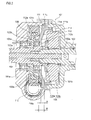
- FIG. 2 An example of the conventional electric power steering system having the housing formed with a metallic material is illustrated in Fig. 2 .
- a housing 101 has therein an input shaft 102, an output shaft 103, and a torque sensor 108 which detects steering force input to the input shaft 102, as steering torque.
- the input shaft 102 is supported by a rolling bearing (not illustrated) so as to be rotatable with respect to the housing 101.
- the output shaft 103 is supported by two rolling bearings 105a and 105b so as to be rotatable with respect to the housing 101.
- Cylindrical holes 102a and 103a respectively concentric with their shaft centers are formed in the input shaft 102 and the output shaft 103.
- a torsion bar 104 is inserted into the cylindrical holes 102a and 103a.
- the input shaft 102 and the output shaft 103 are connected to each other via the torsion bar 104.
- One end portion of the torsion bar 104 and the input shaft 102 are provided with a communication hole 106 communicating with a fitting portion between the one end portion of the torsion bar 104 and the input shaft 102 in a radial direction and are connected to each other by inserting a pin (not illustrated) into the communication hole 106.
- the other end portion of the torsion bar 104 and the output shaft 103 are provided with a communication hole (not illustrated) communicating with a fitting portion between the other end portion of the torsion bar 104 and the output shaft 3 in the radial direction and are connected to each other by inserting a pin (not illustrated) into the communication hole.
- a steering wheel On the right end side (not illustrated) of the input shaft 102, a steering wheel is integrally attached thereto in a rotary direction.
- a universal joint for example, a pinion shaft configuring a known rack and pinion-type steering system is connected thereto. Accordingly, steering force generated by a steering operator who steers the steering wheel is transmitted to the steering wheel via the input shaft 102, the torsion bar 104, the output shaft 103, the universal joint, and the rack and pinion-type steering system.
- a worm wheel 109 which rotates coaxially and integrally with the output shaft 103 is fit externally.
- the steering auxiliary torque is calculated based on a detection value obtained through the torque sensor 108 which detects steering force transmitted to the input shaft 102 via the steering wheel, as steering torque (and/or a steering angle).
- the torque sensor 108 is an electromagnetic induction sensor and is formed with a first sensor member 108a which includes a magnetic member such as a permanent magnet, and a second sensor member 108b which includes a member configuring a magnetic circuit.
- the first sensor member 108a is fixed to the output shaft 103, whereas the second sensor member 108b is fixed to the input shaft 102.
- Steering torque (and/or a steering angle) is detected through relative angle displacement between the first sensor member 108a and the second sensor member 108b occurring when steering force is transmitted to the input shaft 102.
- the steering assist mechanism applying steering auxiliary torque includes the torque sensor 108 and is included inside the housing 101 together with the input shaft 102 and the output shaft 103.
- the housing 101 is configured to have an output side housing member 101a, a bearing support housing member 101c, and an input side housing member 101b.
- the output side housing member 101a has therein the output shaft 103, the worm wheel 109, and the worm 110a.
- the output side housing member 101a rotatably supports the output shaft 103 via the rolling bearing 105a.
- a motor attachment portion (not illustrated) for attaching the electric motor 110 is provided inside the output side housing member 101a.
- the output side housing member 101a is formed with a metallic material such as aluminum.
- the input side housing member 101b has therein the input shaft 102 and the torque sensor 108.
- the input side housing member 101b is also formed with a metallic material such as aluminum.
- the output side housing member 101a and the input side housing member 101b are shaped to have the same outer circumferential surfaces at a joining position thereof and are joined with each other by a bolt and the like (not illustrated). Accordingly, the inside of the housing 101 is sealed.
- the bearing support housing member 101c supports the rolling bearing 105b which is provided at a position closest to the torque sensor 108 among the rolling bearings 105a and 105b.
- the bearing support housing member 101c rotatably supports the output shaft 103 via the rolling bearing 105b.
- the bearing support housing member 101c is provided with a first portion 111 which is press-fitted on an inner circumferential surface of the output side housing member 101a, and a second portion 112 which supports the rolling bearing 105b. Then, in a cross section along an axial direction of the output shaft 3, the first portion 111 and the second portion 112 are connected to each other by a linear portion 113 which extends obliquely and linearly.
- a large diameter portion 111a fitting an inner circumferential surface of the output side housing member 101a, and a small diameter portion 111b fitting the input side housing member 101b are provided on an outer circumference of the first portion 111 of the bearing support housing member 101c.
- the first portion 111 of the bearing support housing member 101c is fixedly fitted by press-fitting the large diameter portion 111a on the inner circumferential surface of the output side housing member 101a.
- a stepped portion 111c is provided on an end surface of the output side housing member 101a in the axial direction on which the large diameter portion 111a fits.
- the large diameter portion 111a of the bearing support housing member 1c is interposed between the stepped portion 111c and an end surface of the input side housing member 101b, and a position thereof in the axial direction is regulated.
- a fitting portion 112a fitting an outer circumferential surface of the rolling bearing 105b, and a stepped surface 112b coming into contact with one side surface of the rolling bearing 105b in the axial direction are formed.
- the rolling bearing 105b is press-fitted in the fitting portion 112a so as to be supported by the bearing support housing member 101c.
- the bearing support housing member 101c is also formed with a metallic material such as aluminum.
- Patent Document 1 JP-A-2005-306050
- the conventional electric power steering system has the following problems.
- all of a plurality of housing members configuring a housing are formed with a metallic material such as aluminum.
- all of the output side housing member 101a, the input side housing member 101b and the bearing support housing member 101c are formed with a metallic material. Therefore, there is a problem that the housing itself weighs a lot. Since the housing is formed with a metallic material, it is necessary to perform finishing through machining after performing molding through die casting, plastic forming, or the like. As a result, manufacturing steps are complicated.
- an electromagnetic induction sensor When an electromagnetic induction sensor is used as a torque sensor, detection performance of the electromagnetic induction sensor is affected by metal which is disposed on the periphery thereof.
- a bearing support housing member supporting a rolling bearing which is provided at a position closest to the torque sensor is also formed with a metallic material, there is a problem that a space needs to be provided between the electromagnetic induction sensor and the metallic bearing support housing member supporting the rolling bearing which is provided at a position closest to the electromagnetic induction sensor among the rolling bearings, to the extent in which detection performance of the sensor is not affected.
- the bearing support housing member 101c is formed with a metallic material.
- a distance A in the axial direction between the bearing support housing member 101c which is a metallic member closest to the electromagnetic induction sensor in an axial direction configuring the torque sensor 108, and the electromagnetic induction sensor (the torque sensor) 108 is a relatively long distance not affecting the detection performance of the electromagnetic induction sensor.
- a distance B in the axial direction between a rolling bearing 105b and the electromagnetic induction sensor is a relatively long distance not affecting the detection performance of the electromagnetic induction sensor.
- the present invention has been made to solve the problems and an object thereof is to provide an electric power steering system in which a housing includes at least one bearing support housing member supporting at least one rolling bearing which supports an output shaft so as to be rotatable with respect to the housing, and weight reduction of the housing itself can be achieved while processing of the housing can be simply performed in the electric power steering system configured to have a plurality of housing members.
- Another object of the present invention is to provide the electric power steering system in which flexibility of the layout can be ensured and sufficient collapse strokes can be ensured even when the electromagnetic induction sensor is used as the torque sensor.
- an electric power steering system comprising: an input shaft; an output shaft which is connected to the input shaft via a torsion bar; a torque sensor which detects steering force input to the input shaft as steering torque; a housing which includes therein the input shaft, the output shaft and the torque sensor; and at least one rolling bearing which supports the output shaft rotatably with respect to the housing, wherein the housing includes at least one bearing support housing member supporting the at least one rolling bearing and is configured by a plurality of housing members, and wherein the bearing support housing member supporting the at least one rolling bearing is formed of a resin.
- the resin can be continuously used in a temperature environment ranging from -40°C to 85°C and the resin is made of a resin composition containing a fibrous filler ranging from 30% by mass to 55% by mass.
- the coefficient of linear expansion of the resin ranges from 1.2 x 10 -5 to 5.5 ⁇ 10 -5 (1/°C) in both a fiber direction and a perpendicular direction to the fiber direction in a temperature range from 23°C to 80°C and a coefficient of water absorption of the resin is equal to or less than 4% when being left in the water at a temperature of 23°C for 24 hours.
- a retention of tensile strength of the resin is equal to or greater than 70% after being left under an environment of 85°C and RH 85% for 500 hours.
- a bearing support housing member supporting a rolling bearing which is provided at a position closest to the torque sensor among the rolling bearings is formed of the resin, and the torque sensor is an electromagnetic induction sensor.
- the bearing support housing member supporting the rolling bearing which is provided at the position closest to the torque sensor among the rolling bearings includes a first portion which is press-fitted onto an inner circumferential surface of a different housing member, and a second portion which supports the rolling bearing provided at the position closest to the torque sensor among the rolling bearings, the first portion and the second portion are connected to each other through a bent portion bent at a predetermined angle which is an acute angle or obtuse angle formed therebetween in a cross section along an axial direction of the output shaft, or a curved portion which has a curved shape in a cross section along the axial direction of the output shaft, and the rolling bearing provided at the position closest to the torque sensor among the rolling bearings is supported by being press-fitted in the bearing support housing member so as to be fixedly fitted therein.
- the bearing support housing member supporting the rolling bearing which is provided at the position closest to the torque sensor among the rolling bearings may have a function to hold the torque sensor.
- a ring reinforcement (a metallic collar) may be arranged in each of the press-fit portions through an insert molding method. Even when there is no ring reinforcement, the resin bearing support housing member can be used inside a vehicle for a long period of time. However, when the ring reinforcement is arranged, it is possible to be stably used inside an engine compartment, that is, a more severe temperature region (up to 120°C) for a long period of time.
- the ring reinforcement is arranged by performing insert molding.
- the ring reinforcement may be coated with a heat curing adhesive in its entirety before being subjected to insert molding.
- the ring reinforcement may be previously coated with the adhesive in its entirety, and be heated and dried until the ring reinforcement is in a semi-cured state. Thereafter, the ring reinforcement coated with the adhesive may be set to a metal mold, thereby performing insert molding of the resin.
- a material of the ring reinforcement for example, carbon steel for machine construction such as S53C, SUJ2 which is so-called bearing steel, a cold rolled steel sheet such as SPCC, or stainless steel such as SUS430 and SUS410 can be used.
- carbon steel for machine construction such as S53C, SUJ2 which is so-called bearing steel
- a cold rolled steel sheet such as SPCC
- stainless steel such as SUS430 and SUS410
- light metals such as an aluminum alloy and a magnesium alloy are suitably selected.
- the surface of the ring reinforcement is processed to have appropriate surface roughness through a technique such as a shot blast method or a chemical etching method.
- a priming adhesive containing a phenol resin and an epoxy resin, or a coupling agent-based primer such as a silane-based primer, a chromium-based primer, a titanium-based primer, and an aluminate-based primer is suitably selected as the primer.
- a phenol resin-based adhesive is suitably selected as the final coating adhesive.
- the priming adhesive containing a phenol resin and an epoxy resin is used as an organic solvent solution which is dissolved in a single solvent such as isopropyl alcohol, methyl ethyl ketone, and methyl isobutyl ketone; or in a mixed solvent so as to have a component concentration ranging approximately from 0.5% by mass to 20% by mass.
- the coupling agent adopted as a primer is used after being diluted with water, alcohol, or a mixed solvent of water and alcohol so as to have a component concentration ranging from 0.1% by mass to 2.0% by mass.
- the ring reinforcement according to the present invention is coated with the above priming adhesive and primer in a thickness ranging approximately from 0.5 ⁇ m to 5 ⁇ m through a method such as immersion coating, spray coating, and brush coating. Then, after being dried at room temperature, the priming adhesive and the primer are baked under drying and curing conditions of a temperature ranging approximately from 150°C to 250°C and a period of time ranging approximately from 5 minutes to 30 minutes.
- the final coating adhesive is adjusted as an organic solvent solution in which an adhesive composition having a resol-type phenol resin as the main component is dissolved to have a solid component concentration ranging approximately from 5% by mass to 40% by mass.
- the drying and curing conditions for example, the final coating adhesive is dried under conditions of a temperature ranging from 100°C to 150°C and a period of time ranging approximately from several minutes to 30 minutes, and then, the final coating adhesive is baked onto the ring reinforcement in a semi-cured state to the extent that the final coating adhesive is not washed away by a fusion resin at a high temperature and high pressure during insert molding. Then, the final coating adhesive is completely cured by heat from the fusion resin during insert molding, and moreover, by secondary heating (for example, approximately at 150°C, for two hours) succeeding thereafter.
- secondary heating for example, approximately at 150°C, for two hours
- a bearing support housing member supporting at least one rolling bearing is formed of a resin.
- the bearing support housing member is formed with a metallic material.
- a housing includes at least one bearing support housing member supporting the at least one rolling bearing which supports the output shaft so as to be rotatable with respect to the housing, and weight reduction of the housing itself can be achieved in the electric power steering system configured to have a plurality of housing members.
- the bearing support housing member is formed of a resin, the bearing support housing member can be processed with high precision by only performing molding such as injection molding, and thus, it is possible to make processing of the bearing support housing member simple.
- the resin can be continuously used in a temperature environment ranging from -40°C to 85°C
- the resin is made of a resin composition containing a fibrous filler ranging from 30% by mass to 55% by mass
- a coefficient of linear expansion of the resin ranges from 1.2 ⁇ 10 -5 to 5.5 ⁇ 10 -5 (1/°C) in both a fiber direction and a perpendicular direction to the fiber direction in a temperature range from 23°C to 80°C
- a coefficient of water absorption of the resin is equal to or less than 4% when being left in the water at the temperature of 23°C for 24 hours.
- the resin portion when being repeatedly exposed to a high-temperature environment which is assumed to occur in an automobile and the like, the resin portion can be prevented from being damaged due to degradation of mechanical properties of the bearing support housing member formed with such a resin composition, occurring under a high-temperature environment.
- the resin portion can be prevented from being damaged due to pressure applied to the rolling bearing and the housing supported by the bearing support housing member, caused through expansion of the resin under environments of high temperature and high humidity.
- Under a low-temperature environment it is possible to resolve an occurrence of a gap generated in a fitting portion between the bearing support housing member and the housing, caused by a difference in coefficients of linear expansion between a metallic material and a resin material.
- the resin has a retention of tensile strength equal to or greater than 70% after being left under an environment of 85°C and RH 85% for 500 hours. Accordingly, when being exposed to environments of high temperature and high humidity for a long period of time during transportation and the like, the resin portion can be prevented from being damaged due to degradation of mechanical properties arising from deterioration of the resin-formed bearing support housing member caused by moisture absorption.
- the bearing support housing member supporting the rolling bearing which is provided at a position closest to a torque sensor among the rolling bearings is formed of the resin, and the torque sensor is an electromagnetic induction sensor
- detection performance of the electromagnetic induction sensor is not affected by the bearing support housing member. Accordingly, the electromagnetic induction sensor and the bearing support housing member can be disposed to be close to each other. As a result, when spatial volume inside the housing is the same, the degree of freedom for the inside of the housing can be improved compared to a case where the bearing support housing member is formed with a metallic material.
- the electromagnetic induction sensor can be disposed to be close to the rolling bearing supported by the bearing support housing member, the dimensions of the housing and the output shaft in the axial direction can be decreased, and the flexibility of the layout for the outside of the housing can be improved as well. Thus, for example, collapse strokes of a steering column can be increased.
- the bearing support housing member supporting the rolling bearing provided at the position closest to the torque sensor among the rolling bearings includes a first portion which is press-fitted onto an inner circumferential surface of a different housing member, and a second portion which supports the rolling bearing provided at the position closest to the torque sensor among the rolling bearings; and the first portion and the second portion are connected to each other through a bent portion bent at a predetermined angle which is an acute angle or obtuse angle formed therebetween in a cross section along an axial direction of the output shaft, or a curved portion which has a curved shape in a cross section along the axial direction of the output shaft, expansion of the bearing support housing member is absorbed by the bent portion or the curved portion.
- the bearing support housing member can be prevented from being damaged.
- a ring reinforcement may be arranged in each of the press-fit portions through an insert molding method.
- a more severe temperature region inside an engine compartment, up to 120°C for a long period of time.
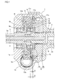
- a housing 1 has therein an input shaft 2, an output shaft 3, and a torque sensor 8 which detects steering force input to the input shaft, as steering torque.
- the input shaft 2 is supported by a rolling bearing (not illustrated) so as to be rotatable with respect to the housing 1.
- the output shaft 3 is supported by two rolling bearings 5a and 5b so as to be rotatable with respect to the housing 1.
- Cylindrical holes 2a and 3a respectively concentric with their shaft centers are formed in the input shaft 2 and the output shaft 3.
- a torsion bar 4 is inserted into the cylindrical holes 2a and 3a.
- the input shaft 2 and the output shaft 3 are connected to each other via the torsion bar 4.
- One end portion of the torsion bar 4 and the input shaft 2 are provided with a communication hole 6 communicating with a fitting portion between the one end portion of the torsion bar 4 and the input shaft 2 in a radial direction and are connected to each other by inserting a pin 7 into the communication hole 6.
- the other end portion of the torsion bar 4 and the output shaft 3 are provided with a communication hole (not illustrated) communicating with a fitting portion between the other end portion of the torsion bar 4 and the output shaft 3 in the radial direction and are connected to each other by inserting a pin (not illustrated) into the communication hole.
- Serrations may be formed at both end portions of the torsion bar 4 so as to respectively connect both the end portions of the torsion bar 4 to the input shaft 2 and the output shaft 3 by being press-fitted in a cylindrical hole 2a of the input shaft 2 and a cylindrical hole 3a of the output shaft 3.
- the one end portion of the torsion bar 4 may be joined to the input shaft 2 or the output shaft 3 by using the pin, and the other end portion of the torsion bar 4 may be joined to the output shaft 3 or the input shaft 2 by performing serration press-fitting.
- a steering wheel On the right end side (not illustrated) of the input shaft 2, a steering wheel is integrally attached thereto in a rotary direction.
- a pinion shaft configuring a known rack and pinion-type steering system is connected thereto. Accordingly, steering force generated by a steering operator steering the steering wheel is transmitted to the steering wheel via the input shaft 2, the torsion bar 4, the output shaft 3, the universal joint, and the rack and pinion-type steering system.
- a worm wheel 9 which rotates coaxially and integrally with the output shaft 3 externally fits.
- a resin engagement portion 9a provided in the worm wheel 9 and a worm 10a formed on an outer circumferential surface of the output shaft (not illustrated) of an electric motor 10 engage each other. Accordingly, rotary force of the electric motor 10 is transmitted to the output shaft 3 via its output shaft, the worm 10a and the worm wheel 9, thereby applying steering auxiliary torque to the output shaft 3 in an arbitrary direction by suitably switching the rotary direction of the electric motor 10.
- the steering auxiliary torque is calculated based on a detection value obtained through the torque sensor 8 which detects steering force transmitted to the input shaft 2 via the steering wheel, as steering torque (and/or a steering angle).
- the torque sensor 8 is an electromagnetic induction sensor and includes a first sensor member 8a which includes a magnetic member such as a permanent magnet, and a second sensor member 8b which includes a member configuring a magnetic circuit.
- the first sensor member 8a is fixed to the output shaft 3.
- the second sensor member 8b is fixed to the input shaft 2.
- Steering torque (and/or a steering angle) is detected through relative angle displacement between the first sensor member 8a and the second sensor member 8b occurring when steering force is transmitted to the input shaft 2.
- the steering assist mechanism applying steering auxiliary torque includes the torque sensor 8 and is included inside the housing 1 together with the input shaft 2 and the output shaft 3.
- the housing 1 is configured to have an output side housing member 1a, a bearing support housing member 1c, and an input side housing member 1b.
- the output side housing member 1a has therein the output shaft 3, the worm wheel 9, and the worm 10a.
- the output side housing member 1a rotatably supports the output shaft 3 via the rolling bearing 5a.
- a motor attachment portion (not illustrated) for attaching the electric motor 10 is provided inside the output side housing member 1a.
- the output side housing member 1a is formed with a metallic material such as aluminum.
- the input side housing member 1b has therein the input shaft 2 and the torque sensor 8.
- the input side housing member 1b is also formed with a metallic material such as aluminum.
- the output side housing member 1a and the input side housing member 1b are shaped to have the same outer circumferential surfaces at a joining position thereof and are joined with each other by a bolt and the like (not illustrated). Accordingly, the inside of the housing 1 is sealed.
- the bearing support housing member 1c supports the rolling bearing 5b which is provided at a position closest to the torque sensor 8 among the rolling bearings 5a and 5b.
- the bearing support housing member 1c rotatably supports the output shaft 3 via the rolling bearing 5b.
- the bearing support housing member 1c is provided with a first portion 11 which is press-fitted on an inner circumferential surface of the output side housing member 1a, and a second portion 12 which supports the rolling bearing 5b. Then, the first portion 11 and the second portion 12 are connected to each other through a bent portion 13 bent at a predetermined angle ⁇ which is an acute angle or obtuse angle formed therebetween in a cross section along an axial direction of the output shaft 3.
- the first portion 11 and the second portion 12 may be connected to each other through a curved portion (not illustrated) which has a curved shape in a cross section along the axial direction of the output shaft 3, instead of the bent portion 13.
- a large diameter portion 11a fitting an inner circumferential surface of the output side housing member 1a, and a small diameter portion 11b fitting the input side housing member 1b are provided on an outer circumference of the first portion 11 of the bearing support housing member 1c.
- the first portion 11 of the bearing support housing member 1c is fixedly fitted by press-fitting the large diameter portion 11a on the inner circumferential surface of the output side housing member 1a.
- a stepped portion 11c is provided on an end surface of the output side housing member 1a in the axial direction on which the large diameter portion 11a fits.
- the large diameter portion 11a of the bearing support housing member 1c is interposed between the stepped portion 11c and an end surface of the input side housing member 1b such that a position thereof in the axial direction is regulated.
- a fitting portion 12a fitting an outer circumferential surface of the rolling bearing 5b, and a stepped surface 12b coming into contact with one side surface of the rolling bearing 5b in the axial direction are formed.
- the rolling bearing 5b is press-fitted in the fitting portion 12a so as to be supported by the bearing support housing member 1c.
- the bearing support housing member 1c is formed of a resin.
- the bearing support housing member 1c in order to solve such problems, it is preferable to form the bearing support housing member 1c with a resin having the following characteristics.
- the resin it is preferable to form the resin with a resin composition of which mechanical properties are less likely to be degraded and which can be continuously used even in a temperature environment ranging from -40°C to 85°C, that is, a usage environment temperature for a column portion of the electric power steering system.
- a temperature environment ranging from -40°C to 85°C, that is, a usage environment temperature for a column portion of the electric power steering system.
- dimensional stability is high.
- the coefficient of linear expansion of the resin ranges from 1.2 ⁇ 10 -5 to 5.5 ⁇ 10 -5 (1/°C) in both a fiber direction and a perpendicular direction to the fiber direction in a temperature range from 23°C to 80°C, and the coefficient of water absorption of the resin is equal to or less than 4% when being left in the water at the temperature of 23 °C for 24 hours.
- the resin has a retention of tensile strength equal to or greater than 70% after being left under an environment of 85°C and RH 85% for 500 hours.
- the resin composition which can be continuously used even in a temperature environment ranging from -40°C to 85°C without being particularly limited, it is possible to exemplify so-called engineering plastic such as polyethylene terephthalate (PET), polybutylene terephthalate (PBT), polyamide (PA) 6, polyamide 11, polyamide 12, polyamide 66, polyamide 610, polyamide 612, polyamide 46, polyamide 410, modified polyamide 6T, and polyamide 9T; and a so-called super engineering plastic resin such as a fluorine resin, polyphenylene sulfide (PPS), polyether sulfone (PES), polyetherimide (PEI), polyamide-imide (PAI), thermoplastic polyimide, polyether ether ketone (PEEK), and polyether nitrile (PEN).
- engineering plastic such as polyethylene terephthalate (PET), polybutylene terephthalate (PBT), polyamide (PA) 6, polyamide 11, polyamide 12, polyamide 66, poly
- polyethylene terephthalate (PET), polyamide 66, polyamide 46, and polyphenylene sulfide are well balanced between cost and performance, and thus, these can be suitably used.
- PET polyethylene terephthalate
- polyamide 66, polyamide 46, and polyphenylene sulfide are well balanced between cost and performance, and thus, these can be suitably used.
- a heat curing resin such as a phenol resin, a urea resin, an unsaturated polyester resin, and a polyurethane resin can be suitably used.
- the coefficient of linear expansion of the resin ranges from 1.2 ⁇ 10 -5 to 5.5 ⁇ 10 -5 (1/°C) in both the fiber direction and the perpendicular direction to the fiber direction in the temperature range from 23°C to 80°C.
- the coefficient of linear expansion is smaller than 1.2 ⁇ 10 -5 (1/°C)
- the coefficient of linear expansion of the rolling bearing 5b press-fitted in the bearing support housing member 1c on the inner diameter side is 1.2 ⁇ 10 -5 (1/°C)
- the coefficient of linear expansion is greater than 5.5 ⁇ 10 -5 (1/°C)
- the output side housing member 1a is pressurized at the time of expansion, and excessive load stress is generated, thereby causing a problem of damage to the bearing support housing member 1c.
- the fibrous filler is not particularly limited.
- a glass fiber, a carbon fiber, a metal fiber, an aramid fiber, an aromatic polyimide fiber, a liquid crystalline polyester fiber, a silicon carbide fiber, an alumina fiber, and a boron fiber can be exemplified.
- a glass fiber and a carbon fiber have favorable reinforcement properties, thereby being preferable.
- a glass fiber it is more preferable to use a glass fiber which is an insulator and is less likely to affect electromagnetic induction of the torque sensor 8.
- the percentage of content of the fibrous filler in the entire composition ranges from 30% by mass to 55% by mass, and is preferably to range from 35% by mass to 55% by mass. If the fibrous filler is compounded exceeding 55% by mass, it not only leads to poor molding characteristics caused by rapid degradation of fusion fluidity of the resin composition but also it cannot be expected that mechanical characteristics and dimensional stability are further improved. On the contrary, deformability of the material is extremely decreased, and thus, there is a concern of damage to the bearing support housing member 1c at the time of molding or assembling the bearing support housing member 1c. In contrast, if the percentage of content of the fibrous filler among the entire composition is smaller than 30% by mass, a reinforcement effect for mechanical characteristics decreases and dimensional stability becomes insufficient.
- the dimensional stability specifically denotes that the coefficient of linear expansion of the resin ranges from 1.2 ⁇ 10 -5 to 5.5 ⁇ 10 -5 (1/°C) in both the fiber direction and the perpendicular direction to the fiber direction in the temperature range from 23°C to 80°C, and the coefficient of water absorption of the resin is equal to or less than 4% when being left in the water at the temperature of 23°C for 24 hours.
- the fibrous filler in order to improve adherence and dispersibility between the resin and the fibrous filler by granting compatibility between the resin and the fibrous filler, can be processed by using a coupling agent such as a silane-based coupling agent and a titanate-based coupling agent, or a surface treatment agent corresponding to the purpose, without being limited thereto.
- a coupling agent such as a silane-based coupling agent and a titanate-based coupling agent, or a surface treatment agent corresponding to the purpose, without being limited thereto.
- hydrolysis inhibitor added to the polyester-based base resin which is used to the bearing support housing member of the present invention.
- the hydrolysis inhibitor may be added to the polyester-based resin in the amount ranging from 0.01% by mass to 5% by mass, and may be preferably added thereto in the amount ranging from 0.05% by mass to 2% by mass.
- the mixing method of the base resin, the fibrous filler, and the additive agent it is possible to exemplify a method of cooling and pelletizing followed by a process of impregnation of a continuous fiber bundle of the fibrous filler in a fusion resin in which various additive agents other than the fibrous filler are compounded.
- the temperature during fusion impregnation is not particularly limited. However, the temperature may be appropriately selected in a temperature range in which fusion of the resin which becomes the parent material proceeds sufficiently and the resin is not deteriorated.
- the manufacturing method of the bearing support housing member 1c is not particularly limited.
- the bearing support housing member 1c can be molded through an ordinary method such as injection molding, compression molding, and transfer molding.
- the injection molding method excels in productivity and is able to provide an inexpensive bearing support housing member 1c, thereby being preferable.
- a ring reinforcement (a metallic collar) may be arranged in each of the press-fit portions through an insert molding method.
- the surface of the ring reinforcement is processed to have appropriate surface roughness through a technique such as a shot blast method or a chemical etching method.
- the ring reinforcement may be previously coated with an adhesive, and be heated and dried until the ring reinforcement is in a semi-cured state. Thereafter, the ring reinforcement coated with the adhesive may be set to a metal mold, thereby performing insert molding of the resin.
- bearing support housing member 1c is formed of the resin exemplified above, it is possible to achieve weight reduction compared to a case where the bearing support housing member 1c is formed with a metallic material.
- the bearing support housing member 1c is formed with a metallic material, it is necessary to perform finishing through machining after performing molding through die casting, plastic forming, or the like. Therefore, manufacturing steps are complicated.
- the bearing support housing member 1c according to the present embodiment is formed of the resin which excels in dimensional stability, the bearing support housing member 1c can be processed with high precision by only performing molding such as injection molding. Accordingly, it is possible to omit finishing performed through machining after performing molding of the bearing support housing member 1c. That is, the bearing support housing member 1c can be simply manufactured. As a result, manufacturing steps can be decreased and a yield rate is also improved. Thus, it is possible to reduce the manufacturing cost.
- the bearing support housing member 1c supporting the rolling bearing 5b which is provided at the position closest to the torque sensor 8 among the housing members 1a and 1c supporting the rolling bearings 5a and 5b is formed of the resin.
- the torque sensor 8 is configured to be an electromagnetic induction sensor. As a result, detection performance of the electromagnetic induction sensor is not affected by the bearing support housing member 1c. Accordingly, the electromagnetic induction sensor configuring the torque sensor 8 and the bearing support housing member 1 c can be disposed to be close to each other. That is, when the bearing support housing member 1c is formed with a metallic material such as that in conventional art illustrated in Fig.
- a distance A in the axial direction between the bearing support housing member 1c and the electromagnetic induction sensor it is necessary to cause a distance A in the axial direction between the bearing support housing member 1c and the electromagnetic induction sensor to be a relatively long distance not affecting the detection performance of the electromagnetic induction sensor.
- the bearing support housing member 1c is formed of a resin, it is sufficient that a distance B in the axial direction between the rolling bearing 5b which is a metallic member closest to the electromagnetic induction sensor in the axial direction configuring the torque sensor 8, and the electromagnetic induction sensor is a distance not affecting detection performance of the electromagnetic induction sensor.
- the spatial volume inside the housing 1 is the same, the degree of freedom for the inside of the housing can be improved compared to a case where the bearing support housing member 1c is formed with a metallic material.
- the spatial volume inside the housing 1 is variable, since the electromagnetic induction sensor and the rolling bearing 5b can be disposed to be close to each other by the difference between the distances A and B, the dimensions of the housing 1 and the output shaft 3 in the axial direction can be decreased.
- the flexibility of the layout for the outside of the housing can be improved as well.
- collapse strokes of a steering column can be increased.
- the bearing support housing member 1c is formed of the resin, the bearing support housing member 1c and the electromagnetic induction sensor configuring the torque sensor 8 can be caused to come into contact with each other. That is, when the bearing support housing member 1c is formed with a metallic material such as that in the conventional art, it is necessary to cause the distance A between the bearing support housing member 1c and the electromagnetic induction sensor to be a distance not affecting the detection performance of the electromagnetic induction sensor. Therefore, in order to hold a sensor detection portion itself, there is a need to adopt a nonmetallic member, that is, mainly a resin member between a sensor main body and the bearing support housing member 1c (metal). As a result, there is a limitation in the layout for the periphery of the sensor.
- the bearing support housing member 1c since the bearing support housing member 1c is formed of the resin, the bearing support housing member 1c can directly hold the sensor itself, or a nonmetallic member can be contracted in size. As a result, the flexibility of the layout for the periphery of the sensor can be ensured.
- a convex portion may be provided in the electromagnetic induction sensor so as to function to hold the electromagnetic induction sensor configuring the torque sensor 8 in the bearing support housing 1c
- a concave portion engaging the convex portion may be provided in the bearing support housing member 1c. As the convex portion and the concave portion engage each other, the electromagnetic induction sensor can be subjected to rotation locking.
- the bearing support housing member 1c supporting the rolling bearing 5b which is provided at the position closest to the torque sensor 8 is provided with the first portion 11 which is press-fitted on the inner circumferential surface of a different housing member 1a, and the second portion 12 supporting the rolling bearing 5b which is provided at the position closest to the torque sensor 8. Then, the first portion 11 and the second portion 12 are connected to each other through the bent portion 13 bent at the predetermined angle ⁇ which is an acute angle or obtuse angle formed therebetween in a cross section along an axial direction of the output shaft 3, or through the curved portion which has a curved shape in a cross section along the axial direction of the output shaft 3. Therefore, expansion of the bearing support housing member 1c is absorbed through the bent portion 13 or the curved portion, and thus, it is possible to prevent the bearing support housing member 1c from being damaged.
- the first portion 111 and the second portion 112 in the bearing support housing member 101c illustrated in Fig. 2 are connected to each other in a cross section along an axial direction of the output shaft 3 through a linear portion 113 which extends obliquely and linearly. If a resin is used for a material of the bearing support housing member 101c in such a configuration, when the bearing support housing member 101c expands, the linear portion 113 cannot smoothly absorb expansion thereof. Thus, there is a concern of damage to the bearing support housing member 101 c.
- the bearing support housing member 1c supporting the rolling bearing 5b which is provided at the position closest to the torque sensor 8 among the rolling bearings 5a and 5b is formed of the resin.
- the output side housing member 1a supporting the rolling bearing 5a may be formed of a resin, or only the output side housing member 1a may be formed of a resin.
- the torque sensor 8 is not necessarily configured by the electromagnetic induction sensor.
- the bearing support housing member 1c supporting the rolling bearing 5b which is provided at the position closest to the torque sensor 8 needs to be formed of a resin.
- the torque sensor 8 is not configured by the electromagnetic induction sensor, among the housing members 1a and 1c supporting the rolling bearings 5a and 5b, only the output side housing member 1a, only the bearing support housing member 1c, or both of the housing members 1a and 1c may be formed of a resin.
- the bearing support housing member 1c supporting the rolling bearing 5b which is provided at the position closest to the torque sensor 8, among the rolling bearings 5a and 5b is press-fitted on the inner circumferential surface of a different housing member (the output side housing member 1a) so as to be fixedly fitted therein.
- the rolling bearing 5b which is provided at the position closest to the torque sensor 8 among the rolling bearings 5a and 5b does not have to be supported by being press-fitted in the bearing support housing member 1c supporting the rolling bearing 5b so as to be fixedly fitted therein.
- Table 1 shows respective composition ratios (% by mass), coefficients of linear expansion (1/°C), and coefficients of water absorption (%) of the resin materials of Examples 1 to 6 and Comparison Examples 1 to 5.
- Base Resin Filling Fibers Filling Volume (% by mass) Coefficients of Linear Expansion ⁇ 10 -5 [1/°C] Coefficients of Water Absorption (%) Vertical Direction Lateral Direction
- PET (with hydrolysis prevention) ⁇ 50 2.0 3.5 0.3
- Example 4 PPS ⁇ 30 2.0 4.0 0.02
- Comparparison Example 1 PET - 0 7.0 7.0 0.8
- Comparparison Example 3 nylon
- Each of the resin materials in Examples 1 to 6 and Comparison Examples 1 to 5 was molded into a doughnut-shaped disk test piece having an inner diameter of 30 mm, an outer diameter of 100 mm, and a thickness of 3 mm.
- the inner diameter and the outer diameter thereof were subjected to machining so as acquire the above dimensions, and tightening margin with respect to the below-described aluminum ring was adjusted so as to be 0.05 mm at a temperature of 23°C.
- an aluminum ring having an inner diameter of 20 mm, an outer diameter of 30.05 mm, and a thickness of 3 mm was press-fitted.
- an aluminum ring having an inner diameter of 99.95 mm, an outer diameter of 110 mm, and a thickness of 3 mm was press-fitted.
- a low-temperature exposure test, a high-temperature exposure test, and a water absorption test were carried out.
- the rings and test piece (the resin portion) were checked to see whether there is an occurrence of coming-off or damage.
- the further tests were carried out with only the test piece in which the ring did not come off.
- the impact test was carried out with only the evaluation product which went through the low-temperature test.
- Comparison Example 1 the PET resin, no filling fiber contained
- coming-off of the rings on the inner diameter side and the outer diameter side was found through the low-temperature test.
- a crack was found in the resin through the high-temperature test.
- substantive degradation of strength was recognized through the high-temperature high-humidity test.
- Comparison Example 3 the polyamide 66 resin, reinforced with glass fibers of 25% by mass
- coming-off of the ring on the outer diameter side was found through the low-temperature test, and a crack was found in the resin through the high-temperature test.
- a crack was found in the resin through the water absorption test as well.
- a housing is formed with a resin composition having particular strength, is lightweight and easily processed, and further, flexibility of the layout can be ensured and sufficient collapse strokes can be ensured even when an electromagnetic induction torque sensor is used.
Landscapes
- Engineering & Computer Science (AREA)
- Mechanical Engineering (AREA)
- General Engineering & Computer Science (AREA)
- Chemical & Material Sciences (AREA)
- Combustion & Propulsion (AREA)
- Transportation (AREA)
- Power Steering Mechanism (AREA)
- Mounting Of Bearings Or Others (AREA)
- Rolling Contact Bearings (AREA)
Applications Claiming Priority (2)
| Application Number | Priority Date | Filing Date | Title |
|---|---|---|---|
| JP2012251328 | 2012-11-15 | ||
| PCT/JP2013/070394 WO2014077006A1 (ja) | 2012-11-15 | 2013-07-26 | 電動パワーステアリング装置 |
Publications (2)
| Publication Number | Publication Date |
|---|---|
| EP2921372A1 true EP2921372A1 (de) | 2015-09-23 |
| EP2921372A4 EP2921372A4 (de) | 2016-11-02 |
Family
ID=50730931
Family Applications (1)
| Application Number | Title | Priority Date | Filing Date |
|---|---|---|---|
| EP13855855.6A Withdrawn EP2921372A4 (de) | 2012-11-15 | 2013-07-26 | Elektrisches servolenksystem |
Country Status (5)
| Country | Link |
|---|---|
| US (1) | US20150298725A1 (de) |
| EP (1) | EP2921372A4 (de) |
| JP (1) | JPWO2014077006A1 (de) |
| CN (1) | CN104955712A (de) |
| WO (1) | WO2014077006A1 (de) |
Cited By (2)
| Publication number | Priority date | Publication date | Assignee | Title |
|---|---|---|---|---|
| CN108284870A (zh) * | 2017-01-10 | 2018-07-17 | 株式会社万都 | 用于车辆的转向柱 |
| CN117500716A (zh) * | 2021-06-25 | 2024-02-02 | 株式会社捷太格特 | 转向装置 |
Families Citing this family (10)
| Publication number | Priority date | Publication date | Assignee | Title |
|---|---|---|---|---|
| EP3371567B1 (de) * | 2015-11-03 | 2021-07-21 | Basf Se | Vorrichtung und verfahren zur berührungslosen erfassung von drehmomenten, torsionseigenfrequenzen und/oder torsionspendelungen einer welle |
| JP2017124784A (ja) * | 2016-01-15 | 2017-07-20 | Kyb株式会社 | 電動パワーステアリング装置 |
| EP3396207B1 (de) * | 2016-02-02 | 2020-09-30 | NSK Ltd. | Schneckenrad, schneckenbremsvorrichtung und verfahren zur herstellung eines schneckenrads |
| JP6864885B2 (ja) * | 2016-09-20 | 2021-04-28 | 日立Astemo株式会社 | ステアリング装置 |
| JP6404380B2 (ja) * | 2017-02-24 | 2018-10-10 | Thk株式会社 | 軸受部材の取付構造及び減速装置 |
| JP6922716B2 (ja) * | 2017-12-15 | 2021-08-18 | 株式会社ジェイテクト | ステアリング装置 |
| WO2023286384A1 (ja) * | 2021-07-12 | 2023-01-19 | 日本精工株式会社 | 転動装置 |
| JP2023119833A (ja) * | 2022-02-17 | 2023-08-29 | 日本精工株式会社 | 転がり軸受用保持器及び保持器を組み込んでなる転がり軸受 |
| JP7790549B2 (ja) * | 2022-03-11 | 2025-12-23 | 株式会社ジェイテクト | ステアリング装置 |
| DE102023107628A1 (de) * | 2023-03-27 | 2024-10-02 | Schaeffler Technologies AG & Co. KG | Käfig für Wälzlager und Wälzlager mit Käfig |
Family Cites Families (6)
| Publication number | Priority date | Publication date | Assignee | Title |
|---|---|---|---|---|
| JPH08159888A (ja) * | 1994-12-05 | 1996-06-21 | Koyo Seiko Co Ltd | トルクセンサ |
| JP2005306050A (ja) | 2002-10-31 | 2005-11-04 | Nsk Ltd | 電動パワーステアリング装置 |
| JP2007290550A (ja) * | 2006-04-25 | 2007-11-08 | Nsk Ltd | 電動パワーステアリング装置 |
| JP5397672B2 (ja) * | 2008-12-15 | 2014-01-22 | 株式会社ジェイテクト | 電動パワーステアリング装置 |
| JP2012020647A (ja) * | 2010-07-14 | 2012-02-02 | Jtekt Corp | 電動パワーステアリング装置 |
| JP2012251328A (ja) | 2011-06-01 | 2012-12-20 | Takano Co Ltd | 自立型オーニング |
-
2013
- 2013-07-26 EP EP13855855.6A patent/EP2921372A4/de not_active Withdrawn
- 2013-07-26 JP JP2014546892A patent/JPWO2014077006A1/ja active Pending
- 2013-07-26 WO PCT/JP2013/070394 patent/WO2014077006A1/ja not_active Ceased
- 2013-07-26 CN CN201380059646.0A patent/CN104955712A/zh active Pending
- 2013-07-26 US US14/442,780 patent/US20150298725A1/en not_active Abandoned
Cited By (5)
| Publication number | Priority date | Publication date | Assignee | Title |
|---|---|---|---|---|
| CN108284870A (zh) * | 2017-01-10 | 2018-07-17 | 株式会社万都 | 用于车辆的转向柱 |
| US10647345B2 (en) | 2017-01-10 | 2020-05-12 | Mando Corporation | Steering column for vehicle |
| CN108284870B (zh) * | 2017-01-10 | 2020-09-04 | 株式会社万都 | 用于车辆的转向柱 |
| CN117500716A (zh) * | 2021-06-25 | 2024-02-02 | 株式会社捷太格特 | 转向装置 |
| EP4360997A4 (de) * | 2021-06-25 | 2024-10-23 | JTEKT Corporation | Lenkvorrichtung |
Also Published As
| Publication number | Publication date |
|---|---|
| EP2921372A4 (de) | 2016-11-02 |
| WO2014077006A1 (ja) | 2014-05-22 |
| CN104955712A (zh) | 2015-09-30 |
| JPWO2014077006A1 (ja) | 2017-01-05 |
| US20150298725A1 (en) | 2015-10-22 |
Similar Documents
| Publication | Publication Date | Title |
|---|---|---|
| EP2921372A1 (de) | Elektrisches servolenksystem | |
| EP3135935B1 (de) | Trägervorrichtung, fördervorrichtung, inspektionsvorrichtung und werkzeugmaschine | |
| US9702403B2 (en) | Bearing assembly | |
| EP2913246B1 (de) | Elektrische servolenkung | |
| US10001209B2 (en) | Linear expansion reduction of metal component assemblies using composites | |
| US20190093401A1 (en) | Bearing, hinge assemblies, and method of making and using the same | |
| US10648545B2 (en) | Electric linear actuator | |
| CN104578540B (zh) | 旋转电机 | |
| US9958050B2 (en) | Belt pulley and gear nut with such a belt pulley | |
| US9685842B2 (en) | Direct drive motor, conveyance device, inspection device, and machine tool | |
| US11661100B2 (en) | Rack assist electric power steering apparatus | |
| US10059364B2 (en) | Electric power steering apparatus | |
| US10926789B2 (en) | Steering assembly | |
| US9964153B2 (en) | Support device for bearing | |
| EP2988102A1 (de) | Magnetischer codierer und herstellungsverfahren dafür | |
| JP2022033784A (ja) | クリップ、クリップアセンブリ、ならびにその作製および使用方法 | |
| JP6964783B2 (ja) | ステアリングアセンブリ | |
| US11333199B2 (en) | Assembly for a bearing and methods of making and using the same | |
| EP1721757A1 (de) | Lageranordnung für Fahrzeugrad | |
| CN100419291C (zh) | 防电蚀轴承 | |
| US20240199110A1 (en) | Power assisted steering device | |
| JP2023055545A (ja) | ハブユニット軸受 | |
| EP3783247A1 (de) | Gleitkomponente | |
| KR20220117542A (ko) | 모터 |
Legal Events
| Date | Code | Title | Description |
|---|---|---|---|
| PUAI | Public reference made under article 153(3) epc to a published international application that has entered the european phase |
Free format text: ORIGINAL CODE: 0009012 |
|
| 17P | Request for examination filed |
Effective date: 20150515 |
|
| AK | Designated contracting states |
Kind code of ref document: A1 Designated state(s): AL AT BE BG CH CY CZ DE DK EE ES FI FR GB GR HR HU IE IS IT LI LT LU LV MC MK MT NL NO PL PT RO RS SE SI SK SM TR |
|
| AX | Request for extension of the european patent |
Extension state: BA ME |
|
| DAX | Request for extension of the european patent (deleted) | ||
| RA4 | Supplementary search report drawn up and despatched (corrected) |
Effective date: 20161006 |
|
| RIC1 | Information provided on ipc code assigned before grant |
Ipc: F16C 19/06 20060101ALI20160929BHEP Ipc: B62D 5/04 20060101AFI20160929BHEP Ipc: F16C 35/067 20060101ALI20160929BHEP |
|
| 18W | Application withdrawn |
Effective date: 20170428 |
|
| STAA | Information on the status of an ep patent application or granted ep patent |
Free format text: STATUS: THE APPLICATION HAS BEEN WITHDRAWN |