EP2921597B1 - Dispositif d'actionnement - Google Patents
Dispositif d'actionnement Download PDFInfo
- Publication number
- EP2921597B1 EP2921597B1 EP14161161.6A EP14161161A EP2921597B1 EP 2921597 B1 EP2921597 B1 EP 2921597B1 EP 14161161 A EP14161161 A EP 14161161A EP 2921597 B1 EP2921597 B1 EP 2921597B1
- Authority
- EP
- European Patent Office
- Prior art keywords
- receptacle
- actuation device
- optical waveguide
- light
- frame element
- Prior art date
- Legal status (The legal status is an assumption and is not a legal conclusion. Google has not performed a legal analysis and makes no representation as to the accuracy of the status listed.)
- Active
Links
Images
Classifications
-
- E—FIXED CONSTRUCTIONS
- E03—WATER SUPPLY; SEWERAGE
- E03D—WATER-CLOSETS OR URINALS WITH FLUSHING DEVICES; FLUSHING VALVES THEREFOR
- E03D5/00—Special constructions of flushing devices, e.g. closed flushing system
- E03D5/10—Special constructions of flushing devices, e.g. closed flushing system operated electrically, e.g. by a photo-cell; also combined with devices for opening or closing shutters in the bowl outlet and/or with devices for raising/or lowering seat and cover and/or for swiveling the bowl
- E03D5/105—Special constructions of flushing devices, e.g. closed flushing system operated electrically, e.g. by a photo-cell; also combined with devices for opening or closing shutters in the bowl outlet and/or with devices for raising/or lowering seat and cover and/or for swiveling the bowl touchless, e.g. using sensors
Definitions
- the present invention relates to an actuating device for triggering a flush on a toilet or urinal with lighting elements according to the preamble of claim 1.
- an actuator which has at least one display element.
- the display elements comprise a lamp which can be perceived by the user on the front of the plate.
- the illuminant essentially serves to signal the position of the sensors which the user is to actuate for triggering the flush.
- the light source enables the user to recognize in which areas of the plate the hand has to be placed so that the flush is triggered.
- the illuminants radiate into the room, they are designed in practice in such a way that they have a brightness that does not really illuminate the room. Choosing a higher brightness would also blind the user, for example at night, precisely because such panels are typically mounted slightly below eye level. It follows from the technical teaching of EP 2 578 758 the disadvantage that the illuminants cannot be used as night lights.
- document JP2010110570A discloses a dressing table wherein a light beam can be emitted forward from the dressing table towards the user.
- the invention has for its object to provide an actuating device which overcomes the disadvantages of the prior art and can be used in particular as a night light.
- an actuating device for actuating a flushing device of a toilet or a urinal comprises a frame element with a frame wall, the frame wall on the inside by an inner surface, on the outside by an outer surface, on the front by a front face and on the back a rear end surface is delimited, which inner surface delimits a frame opening, an in front of the plate, in particular in contact with the front end surface, which extends at least over the frame opening, at least one lamp arranged behind the plate and at least one detection element for providing a signal for the Flushing device.
- the frame element comprises at least one receptacle for the illuminant, the receptacle penetrating the outer surface of the frame element with at least one or exactly one opening, so that light from the illuminant can be emitted laterally to the frame element through said opening in the outer surface.
- a light glow can be provided starting from the actuating device, which can be emitted laterally from the actuating device in the installed position.
- the user is not blinded by the light, but can nevertheless orientate himself well in the room.
- the illuminant comprises at least one light source, in particular a light-emitting diode, which provides the light via the opening.
- the illuminant comprises at least one light source, in particular a light-emitting diode, and at least one optical waveguide with at least one coupling-in surface and at least one coupling-out surface, the light source emitting the light via the coupling-in surface Coupled optical fiber and decoupled from the optical fiber via the coupling surface.
- the decoupling surface preferably extends completely over the opening in the outer surface.
- the actuating device is installed in the installed state such that the coupling surface lies in front of the wall, on or in which the actuating device is installed.
- the light source or the light source and the optical waveguide are arranged in the said receptacle and are therefore mounted directly on the frame element.
- At least two light sources are arranged per optical waveguide, which couple the light via at least two different coupling surfaces.
- the light source in the form of a light-emitting diode is preferably an RGB light-emitting diode, with which the light can be provided in different colors.
- At least two or exactly two optical waveguides are arranged per outer surface of the frame element.
- the optical fibers are preferably of different lengths.
- the two optical waveguides can be of equal length to one another.
- these are preferably arranged on a common outer surface.
- a single optical waveguide with at least one light source is arranged per outer surface of the frame element.
- the coupling-out surface of the optical waveguide is particularly preferably flush with the outer surface.
- the decoupling surface above the opening forms part of the outer surface.
- the opening is closed with a transparent or translucent window, which window is flush with the outer surface. The light can then be emitted from the lamp through the window.
- flush we mean here that the decoupling surface and the window lie in the same plane as the outer surface.
- the opening preferably extends exclusively over a partial area of the outer surface.
- the opening is particularly preferably directly and immediately adjacent to the front or rear end face of the frame element. Alternatively, the opening can also be enclosed by the outer surface.
- the receptacle preferably extends from the front end face into the frame wall and has a floor which is spaced apart from the front end face and rear end face.
- the receptacle further has at least one stop shoulder and a rear wall opposite the stop shoulder, the stop shoulder and the rear wall providing a stop for the illuminant, in particular for the optical waveguide.
- the receptacle can also have at least one side wall on the side, which connects to the rear wall and connects it to the stop shoulder.
- the plate is preferably form-fitting and / or material-fitting with the frame element connected and provides a stop for the lamp.
- the lamp is preferably in direct contact with the plate with the side facing the plate.
- the distance between the bottom of the receptacle and the plate essentially corresponds to the thickness of the optical waveguide, so that it is clamped between the bottom and the plate.
- the plate particularly preferably protrudes laterally over the frame element, in particular over the outer surface. When viewed in the direction of the surface normal to the plate, the plate thus has a greater extent than the frame element.
- the illuminant is preferably held in the receptacle in a form-fitting and / or material-locking manner.
- the receptacle advantageously has the shape described above.
- the illuminant is preferably connected to the receptacle via an adhesive connection.
- the optical waveguide is particularly preferably held in a form-fitting manner, while the light-emitting diode is cohesively in the receptacle.
- the illuminant in particular the optical waveguide or the two optical waveguides, preferably extends essentially over the entire length of the corresponding side or outer surface.
- the illuminant, in particular the optical waveguide or the two optical waveguides extends essentially over a length of at least 60% or at least 80% of the length of the corresponding side.
- the detection element is preferably a sensor arranged behind the plate. Typically, two detection elements are arranged, one for triggering a full quantity flush and one for triggering a partial quantity flush. Alternatively, the detection element is a button which is mounted in the plate and can be moved relative to the plate.
- the frame element preferably comprises bearing sections for mounting a printed circuit board, on which printed circuit board at least one control unit and possibly the detection element, in particular the sensor, are arranged.
- the lamps are connected to the control unit and can be supplied with energy and / or control signals.
- the control unit itself is connected to a power supply or a battery.
- the greatest side length of the plate is preferably less than 300 mm and has a maximum thickness of 10 mm.
- An arrangement comprises an actuating device as described above and a cistern with a flush valve that is functionally or physically connected to the actuating device.
- a flushing valve arranged in the cistern can be actuated via the actuating device.
- the arrangement further comprises at least one fastening element which can be fastened to a building wall and which provides a receptacle for the actuating device, the frame element being connectable to the receptacle.
- the frame element can be connected to the fastening element, for example via a snap connection.
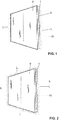
- An actuating device 1 for actuating a flushing device of a toilet or urinal is shown in the figures.
- the actuating device 1 serves to provide a signal for the flushing device so that it can be triggered.
- the signal can be electronic, pneumatic or mechanical.
- the actuating device 1 is connected to a wall or directly to the cistern and is in functional contact with the flushing device, so that said signal can be passed on to the flushing device.
- the flushing device is a drain valve inside a cistern, which directs flushing water into the toilet or urinal.
- the actuating device 1 comprises illuminants 10 which provide a light L L.
- the illuminants 10 are arranged such that the light L can be emitted laterally from the actuating device.
- the lamps 10 can be arranged in different ways or can be controlled in different ways.
- the illuminants 10 are arranged or controlled in such a way that the light radiates from the actuating device 1 laterally, that is to say from the left and from the right.
- the emitted light is shown with dots and bears the reference symbol L.
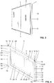
- FIG. 2 Another variant of the actuating device 1 is shown.
- the illuminants 10 are arranged or controlled in such a way that a light L can be provided around the plate.
- the light L illuminates around the plate overleaf.
- the illuminants 10 are arranged or controlled such that the light L can be emitted by the actuating device 1 at the top and bottom.
- the light L can be emitted on all four sides of the plates.
- the illuminants 10 can be arranged accordingly on the respectively desired side or it is possible to arrange the illuminants 10 on all four sides of the actuating device 1 and to control them accordingly with a control if necessary.
- the light L can have many functions.
- the light L preferably serves to provide a night light so that the user of a bathroom can use the light L to orient himself at night without having to operate the main light.
- the light L can also be used to provide information which signals to the user in which state the actuating device 1 is or where the user has to touch the actuating device 1 for triggering the flushing.
- the light can only be provided for a short time, for example, if the flushing has been triggered successfully.
- the receptacle 12 extends along the shorter side of the frame element, a light L being left and right. If a light L is also or alternatively to be emitted downwards or upwards, a corresponding receptacle must be arranged along the longer side.
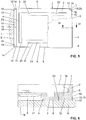
- the actuating device 1 comprises a frame element 2 with a frame wall 3, which frame wall 3 is delimited on the inside by an inner surface 4, on the outside by an outer surface 5, on the front by a front end surface 6 and on the back by a rear end surface 7.
- the inner surface 4 also delimits a frame opening 8 which passes completely through the frame element 2.
- the actuating device 1 comprises a plate 9 which is arranged in front of the front end face 6 and extends at least over the frame opening 8.
- the plate 9 is the element which is perceived by the user in the installed state.
- the actuating device 1 comprises at least one illuminant 10 arranged behind the plate 9.
- the actuating device 1 comprises at least one detection element 11 for providing a signal for the washing device.
- the detection element 11 can also be used to detect a person present in the bathroom.
- the actuating device 1 comprises the frame element 2, the plate 9, the at least one illuminant 10 and the at least one detection element 11.
- the frame element 2 comprises at least one receptacle 12 for the lighting means 10.
- the receptacle 12 penetrates the outer surface 5 of the frame element 2 with at least one or exactly one opening 13.
- the outer surface 5 defines the outside of the frame element 2.
- the opening 13 is light from Illuminant 10 can be emitted laterally to frame element 2 through said opening 13 in outer surface 5. In the installed state, this means that the light can be emitted through the opening 10, which is essentially at right angles to the wall of the bathroom.
- the actuating device 1 can, in the arrangement of the receptacle 12, emit a light L laterally.
- the illuminant 10 can be designed in various ways.
- the illuminant 10 comprises at least one light source 14, in particular in the form of a light emitting diode.
- the light emitting diode is arranged in such a way that it emits the light through the opening 13 in the outer surface 5 of the frame element 2.
- the illuminant 10 comprises at least one light source 14, in particular a light-emitting diode, and at least one optical waveguide 15 with at least one coupling-in surface 16 and at least one coupling-out surface 17.
- the light source 14 couples the light it provides via the Coupling surface 16 into the optical waveguide 15 and the light is coupled out of the optical waveguide 15 via the coupling-out surface 17.
- two light sources 14 are arranged, which couple the light into the optical waveguide 15 via two coupling surfaces 16.
- only a single decoupling surface 17 is arranged, via which the light is decoupled again.
- the decoupling surface 17 extends completely over the opening 13.
- the light source 14 and the optical waveguide 15, if present, are arranged in said receptacle 12.
- the decoupling surface 17 of the optical waveguide 15 is flush with the outer surface 5 of the frame element 2.
- the decoupling surface 17 thus lies in a plane which is spanned by the outer surface 5.
- the decoupling surface 17 provides part of the outer surface 5 in the area of the opening 13.
- the opening 13 can also be closed with a transparent or translucent window.
- the illuminant 10, in particular the optical waveguide 15 or the light source 14, are arranged behind this window.
- the window also runs parallel to the outer surface and extends over the opening 13.
- two optical waveguides 15 are arranged separately from each other per outer surface 5 of the frame element 2. At least one light source 14 couples light into the respective optical waveguide 15.
- the optical waveguides 15 are preferably of different lengths, so that the position of the detection element 11 for the user Full quantity flushing and the position of the detection element 11 can be signaled for a partial quantity flushing.
- a single optical waveguide 15 with at least one light source 14 is arranged per outer surface 5 of the frame element 2.
- the optical waveguide 15 extends essentially completely over the respective side of the frame element 2. This allows a particularly homogeneous light L to be provided.
- the opening 13 preferably extends exclusively over a partial area of the outer surface 5.
- the opening 13 is laterally delimited by parts of the outer surface 5.
- the opening preferably borders directly and directly on the front end face 6 of the frame element 2.
- the opening 13 can also be completely enclosed by the outer surface 5.
- the opening is then particularly preferably located centrally in the outer surface 5.
- the opening 13 is arranged in such a way that it directly adjoins the rear end surface 7.
- the receptacle 12 extends from the front end face 6 into the frame wall and has a bottom 18 which is spaced apart from the front end face 6 and the rear end face 7.
- the lamps 10 can rest on the floor 18 accordingly.
- the plate 9 provides a stop for the lamp 10. Consequently, the lamp 10 is stored between the bottom 18 and the plate 9, in particular slightly clamped. This can be done in the Figure 6 be recognized well.
- the illuminant 10 is arranged between the base 18 and the plate 9 and is in direct contact with both the base 18 and preferably also with the plate.
- the receptacle 12 further comprises, as in FIG Figure 4 and 5 shown, at least one stop shoulder 19.
- the stop shoulder 19 provides a stop for the illuminant 10, in particular for the light waveguide 15, against a movement in the direction of the Outside surface 5 ready.
- the stop shoulder 19 is arranged in such a way that it slightly reduces the opening 13 with respect to the receptacle 12, so that when the stop against the lamp 10 falling out of the receptacle 12 is provided by the opening 13.
- the receptacle 12 has a rear wall 23. Which also acts as a stop for the lamp 10.
- the receptacle 12 is laterally delimited by a side wall 22.
- the illuminant 10 is preferably held in a form-fitting manner by the plate 9, the stop shoulder 19, the rear wall 23 and the bottom 18 in the frame element 2.
- the light source 14 is arranged in the area of the stop shoulder 19, which couples the light into the optical waveguide 15 via the coupling surface 16.
- the optical waveguide 15 comprises a cutout 24 which is essentially complementary to the stop shoulder 19 and cooperates with it.
- a cutout 24 is arranged above and below.
- the coupling surface 16 is also in the region of the cutout 24.
- the illuminant 10 can either lie positively in the receptacle and be secured by the plate and the receptacle in an analogous manner to the optical waveguide 15, or the illuminant 10 can also be held integrally in the receptacle 12.
- the frame element 2 is preferably a rectangle when viewed in the direction of the surface normal N on the plate 9.
- the receptacle 12 can be arranged on different sides of the rectangle. In a first embodiment, the receptacle 12 is arranged on two opposite sides of the rectangle. The light can be emitted either on the short side of the rectangle or on the long side of the rectangle. It is therefore possible to illuminate at the top or bottom left.
- the receptacle 12 is arranged from only one side of the rectangle. So the light is only on one side of the rectangle.
- the receptacle is arranged on two opposite sides of the rectangle and on at least one further side of the rectangle. The light can thus be emitted over three sides of the rectangle.
- the receptacle 12 is arranged on all four sides of the rectangle and a light L can be emitted around the actuating device 1.
- the frame element 2 can also have a different shape.
- the frame element 2 can also be a square, the arrangement of the receptacle 12 with respect to the corresponding sides being identical to the configuration described above for the rectangular frame element. It would also be conceivable for the frame element 2 to be elliptical or round.
- the illuminant 10, in particular the optical waveguide 15, preferably extends essentially over the entire length A of the corresponding side in which the receptacle 12 is arranged.
- the receptacle 12 or the opening 13 extends essentially over the entire length A.
- essentially means that the opening 13, apart from a small edge 25, here in the area of the stop shoulder 19, extends over the largest part of the entire length extends.
- the illuminant 10, in particular the optical waveguide 15, extends essentially over a length A of at least 60% or at least 80% of the length of the corresponding side. It would also be conceivable for the optical waveguide to be substantially shorter with respect to the length A of the corresponding side of the frame element 2.
- a detection element 11 is arranged behind the plate in the area of the frame opening 8. Two detection elements 11 are arranged here.
- the detection elements 11 are particularly preferably two sensors, which can detect the presence of a user and which trigger a corresponding flush when the plate 9 is touched.
- the detection element 11 is a key which is mounted in the plate 9 and can be moved relative to the plate 9.
- the button acts on push rods that work with the drain valve.
- the frame element 2 comprises storage sections 20 for mounting a printed circuit board 21.
- the printed circuit board 21 lies in the frame opening 8.
- Said detection elements 11 are arranged on the printed circuit board 21.
- the printed circuit board also comprises at least one control unit for controlling the lighting means 10, which are electrically connected to the control unit.
- the circuit board 21 can extend over the entire cross section of the frame opening 8 or only over a partial cross section of the frame opening 8.
Landscapes
- Engineering & Computer Science (AREA)
- Aviation & Aerospace Engineering (AREA)
- Health & Medical Sciences (AREA)
- Life Sciences & Earth Sciences (AREA)
- Hydrology & Water Resources (AREA)
- Public Health (AREA)
- Water Supply & Treatment (AREA)
- Arrangement Of Elements, Cooling, Sealing, Or The Like Of Lighting Devices (AREA)
- Non-Portable Lighting Devices Or Systems Thereof (AREA)
Claims (16)
- Dispositif d'actionnement (1) pour l'actionnement d'un dispositif de chasse d'un toilette ou d'un urinoir, comprenant :un élément de cadre (2) avec une paroi de cadre (3), ladite paroi de cadre (3) étant délimitée du côté intérieur par une surface intérieure (4), du côté extérieur par une surface extérieure (5), du côté avant par une surface frontale avant (6) et du côté arrière par une surface frontale arrière (7), ladite surface intérieure (4) délimitant une ouverture de cadre (8) ;une plaque (9) disposée devant la surface frontale avant (6), notamment en contact avec elle, s'étendant au moins sur l'ensemble de l'ouverture de cadre (8) ;au moins un moyen d'éclairage (10) disposé derrière la plaque (9) ; etau moins un élément de détection (11) servant à mettre à disposition un signal pour le dispositif de chasse ;caractérisé en ce que :
l'élément de cadre (2) comprend au moins un logement (12) pour le moyen d'éclairage (10), le logement (12) traversant la surface extérieure (5) de l'élément de cadre (2) avec au moins un ou précisément un passage traversant (13), de sorte que la lumière du moyen d'éclairage (10) puisse être transmise en côté à l'élément de cadre (2) à travers ledit passage traversant (13) réalisé dans la surface extérieure (5). - Dispositif d'actionnement (1) selon la revendication 1, caractérisé en ce que le moyen d'éclairage (10) comprend au moins une source lumineuse (14), notamment une diode d'éclairage, et de préférence au moins un conducteur d'ondes lumineuses (15) avec au moins une surface de couplage (16) et au moins une surface de découplage (17), la source lumineuse (14) couplant la lumière dans le conducteur d'ondes lumineuses (15) via la surface de couplage (16) et la découplant du conducteur d'ondes lumineuses (15) via la surface de découplage (17) et la source lumineuse (14) et/ou le conducteur d'ondes lumineuses (15) étant disposés dans ledit logement (12).
- Dispositif d'actionnement (1) selon la revendication 2, caractérisé en ce qu'au moins deux sources lumineuses (14) sont agencées pour chaque conducteur d'ondes lumineuses (15), lesdites sources couplant la lumière via au moins deux surfaces de couplage (16) différentes.
- Dispositif d'actionnement (1) selon l'une quelconque des revendications 2 à 3, caractérisé en ce qu'au moins deux ou précisément deux conducteurs d'ondes lumineuses (15) par surface extérieure (5) de l'élément de cadre (2) sont disposés avec respectivement au moins une source lumineuse (14), les conducteurs d'ondes lumineuses (15) étant réalisés de préférence de longueur différente ou identique les uns par rapport aux autres et/ou un seul conducteur d'ondes lumineuses (15) par surface extérieure (5) de l'élément de cadre (2) étant disposé avec au moins une source lumineuse (14).
- Dispositif d'actionnement (1) selon l'une quelconque des revendications précédentes, caractérisé en ce que la surface de découplage (17) du conducteur d'ondes lumineuses (15) est en affleurement avec la surface extérieure (5) ou que le passage traversant (13) est fermé avec une fenêtre transparente ou translucide, ladite fenêtre s'étendant en affleurement par rapport à la surface extérieure (5).
- Dispositif d'actionnement (1) selon l'une quelconque des revendications précédentes, caractérisé en ce que le passage traversant (13) s'étend exclusivement sur une zone partielle de la surface extérieure (5), le passage traversant (13) étant de préférence réalisé directement et de façon directement connexe au niveau de la surface frontale avant (6) de l'élément de cadre (2) ou le passage traversant (13) étant entouré par la surface extérieure (5) ou le passage traversant (13) étant réalisé de préférence au niveau de la surface frontale arrière (7) de l'élément de cadre (2), directement et de façon directement connexe.
- Dispositif d'actionnement (1) selon l'une quelconque des revendications précédentes, caractérisé en ce que le logement (12) s'étend depuis la surface frontale avant (6) jusque dans la paroi de cadre (3) et comporte un plancher (18) reposant à une certaine distance de la surface frontale avant (6) et de la surface frontale arrière (7).
- Dispositif d'actionnement (1) selon l'une quelconque des revendications précédentes, caractérisé en ce que le logement (12) comporte au moins un épaulement de butée (19) et une paroi arrière (23) par rapport à l'épaulement de butée (19), l'épaulement de butée (19) et la paroi arrière (23) mettant à disposition une butée pour le moyen d'éclairage (10), notamment pour le conducteur d'ondes lumineuses (15).
- Dispositif d'actionnement (1) selon l'une quelconque des revendications précédentes, caractérisé en ce que la plaque (9) est reliée par complémentarité de formes et/ou par complémentarité de matières à l'élément de cadre (2) et met à disposition une butée pour le moyen d'éclairage (10), notamment pour le conducteur d'ondes lumineuses (15) et/ou que le moyen d'éclairage (10), notamment le conducteur d'ondes lumineuses (15), est en contact direct avec la plaque (9) avec le côté orienté vers la plaque (9).
- Dispositif d'actionnement (1) selon l'une quelconque des revendications précédentes, caractérisé en ce que la plaque (9) ressort en côté au-delà de l'élément de cadre (2), notamment au-delà de la surface extérieure (5).
- Dispositif d'actionnement (1) selon l'une quelconque des revendications précédentes, caractérisé en ce que le moyen d'éclairage (10) est maintenu par complémentarité de formes et/ou par complémentarité de matières dans le logement (12).
- Dispositif d'actionnement (1) selon l'une quelconque des revendications précédentes, caractérisé en ce que l'élément de cadre (2) est un rectangle ou un carré vu dans la direction des normales de surface (N) sur la plaque (9) ;
un logement (12) étant respectivement disposé au niveau des deux côtés opposés du rectangle et/ou du carré ; ou le logement (12) étant disposé exclusivement au niveau d'un côté du rectangle et/ou du carré ; ou
un logement (12) étant respectivement disposé au niveau des deux côtés opposés du rectangle et/ou du carré et étant disposé au niveau d'au moins un côté supplémentaire du rectangle et/ou du carré ; ou
un logement (12) étant respectivement disposé au niveau de l'ensemble des quatre côtés du rectangle et/ou du carré. - Dispositif d'actionnement (1) selon l'une quelconque des revendications 12, caractérisé en ce que le moyen d'éclairage (10), notamment le conducteur d'ondes lumineuses (15), s'étend pour l'essentiel sur l'ensemble de la longueur (A) du côté correspondant ou que le moyen d'éclairage (10), notamment le conducteur d'ondes lumineuses (15), s'étend sur l'ensemble d'une longueur (A) correspondant à au moins 60 % ou à au moins 80 % de la longueur du côté correspondant.
- Dispositif d'actionnement (1) selon l'une quelconque des revendications précédentes, caractérisé en ce que l'élément de détection (11) est un capteur disposé derrière la plaque (9) ou que l'élément de détection (11) est une touche disposée dans la plaque (9) et mobile par rapport à la plaque (9) et/ou que l'élément de cadre (2) comporte des sections de positionnement (20) pour le positionnement d'une plaque conductrice (21), au moins une unité de commande et le cas échéant l'élément de détection (11), notamment le capteur, étant disposés sur la plaque conductrice (21).
- Agencement comprenant un dispositif d'actionnement (1) selon l'une quelconque des revendications précédentes et un caisson de chasse relié sur le plan fonctionnel ou physique au dispositif d'actionnement.
- Agencement selon la revendication 15, caractérisé en ce que l'agencement comprend en outre au moins un élément de fixation pouvant être fixé à une paroi de bâtiment et mettant à disposition un logement pour le dispositif d'actionnement.
Priority Applications (1)
| Application Number | Priority Date | Filing Date | Title |
|---|---|---|---|
| EP14161161.6A EP2921597B1 (fr) | 2014-03-21 | 2014-03-21 | Dispositif d'actionnement |
Applications Claiming Priority (1)
| Application Number | Priority Date | Filing Date | Title |
|---|---|---|---|
| EP14161161.6A EP2921597B1 (fr) | 2014-03-21 | 2014-03-21 | Dispositif d'actionnement |
Publications (2)
| Publication Number | Publication Date |
|---|---|
| EP2921597A1 EP2921597A1 (fr) | 2015-09-23 |
| EP2921597B1 true EP2921597B1 (fr) | 2020-05-13 |
Family
ID=50336223
Family Applications (1)
| Application Number | Title | Priority Date | Filing Date |
|---|---|---|---|
| EP14161161.6A Active EP2921597B1 (fr) | 2014-03-21 | 2014-03-21 | Dispositif d'actionnement |
Country Status (1)
| Country | Link |
|---|---|
| EP (1) | EP2921597B1 (fr) |
Families Citing this family (5)
| Publication number | Priority date | Publication date | Assignee | Title |
|---|---|---|---|---|
| DE102019001578A1 (de) * | 2019-03-08 | 2020-09-10 | Viega Technology Gmbh & Co. Kg | Befestigungsrahmen für eine Betätigungsgsplatte zur Betätigung eines Ventils einer Sanitärinstallation sowie Betätigungsvorrichtung mit einem solchen Befestigungsrahmen und einer Betätigungsplatte |
| DE102019001878B4 (de) * | 2019-03-13 | 2020-11-05 | René Schönig | Vorbauelement |
| IT201900009210A1 (it) * | 2019-06-17 | 2020-12-17 | Kariba Spa | Placca di comando per sanitari da bagno |
| EP3760796B1 (fr) * | 2019-07-02 | 2023-08-16 | Geberit International AG | Arrangement d'un dispositif d'actionnement à détection de l'utilisateur pour une robinette et une robinette |
| DE102020106047A1 (de) * | 2020-03-05 | 2021-09-09 | Tece Gmbh | Berührungslos betätigbare Betätigungsplatte |
Family Cites Families (5)
| Publication number | Priority date | Publication date | Assignee | Title |
|---|---|---|---|---|
| US20110155934A1 (en) * | 2002-03-05 | 2011-06-30 | Fatih Guler | Automatic bathroom flushers |
| JP5324888B2 (ja) * | 2008-11-10 | 2013-10-23 | パナソニック株式会社 | 洗面化粧台 |
| JP2011152330A (ja) * | 2010-01-28 | 2011-08-11 | Lixil Corp | 照明付き鏡装置 |
| EP2497868B1 (fr) * | 2011-03-09 | 2013-08-07 | Geberit International AG | Dispositif de déclenchement électrique d'une sortie d'eau |
| EP2578758B1 (fr) | 2011-10-06 | 2016-11-30 | Geberit International AG | Procédé de réglage de paramètres et dispositif utilisé pour ce procédé |
-
2014
- 2014-03-21 EP EP14161161.6A patent/EP2921597B1/fr active Active
Non-Patent Citations (1)
| Title |
|---|
| None * |
Also Published As
| Publication number | Publication date |
|---|---|
| EP2921597A1 (fr) | 2015-09-23 |
Similar Documents
| Publication | Publication Date | Title |
|---|---|---|
| EP2921597B1 (fr) | Dispositif d'actionnement | |
| EP1832452B1 (fr) | Dispositif d'écoulement d'air avec rétrosignal visuel | |
| DE102009004985A1 (de) | Verkleidungsteil mit Sensor | |
| EP2452434A1 (fr) | Dispositif de commande pour appareil électrique | |
| EP2911141B1 (fr) | Éclairage | |
| AT10559U1 (de) | Schublade mit lichtdurchlassiger wand | |
| DE202009000981U1 (de) | Vorrichtung zur berührungslosen Auslösung eines Spülkastenventils | |
| AT504606B1 (de) | Schalttafel mit wenigstens einem schalter | |
| DE102007054347B3 (de) | Manuell betätigbarer Schalter | |
| DE202007006772U1 (de) | Ladebordwand | |
| DE102007012560A1 (de) | Schaltschrank | |
| EP0335838A2 (fr) | Equipement avec un support et au moins un dispositif électrique de commutation présentant un élément piézoélectrique | |
| EP3262242B1 (fr) | Plaque d'actionnement éclairée | |
| DE102015114632B4 (de) | Signalleuchte für Fahrzeuge, die einen karosserienahen Bereich und einen karosseriefernen Bereich ausleuchtet und dazu zwei gespreizte Lichtleiter verwendet | |
| EP1207542A1 (fr) | Dispositif de commutation électrique illuminé | |
| DE202013101827U1 (de) | Beleuchtungsanordnung mit länglichem Leuchtengehäuse | |
| EP2650606B1 (fr) | Lampe à DEL | |
| EP2631528A1 (fr) | Tube luminescent à DEL | |
| EP2770127A1 (fr) | Dispositif de montage pour un corps sanitaire | |
| EP2709088A2 (fr) | Eclairage | |
| WO2022101250A1 (fr) | Cabine d'ascenseur et dispositif de rayonnement uvc pour cabine d'ascenseur | |
| DE102013102598B3 (de) | Elektrisches/elektronisches Installationsgerät | |
| EP3031989A1 (fr) | Plaque d'actionnement | |
| EP3031988A1 (fr) | Plaque d'actionnement | |
| DE102004057174B4 (de) | Betätigungsvorrichtung für eine sanitäre Armatur und Verfahren zum Betreiben einer solchen |
Legal Events
| Date | Code | Title | Description |
|---|---|---|---|
| PUAI | Public reference made under article 153(3) epc to a published international application that has entered the european phase |
Free format text: ORIGINAL CODE: 0009012 |
|
| AK | Designated contracting states |
Kind code of ref document: A1 Designated state(s): AL AT BE BG CH CY CZ DE DK EE ES FI FR GB GR HR HU IE IS IT LI LT LU LV MC MK MT NL NO PL PT RO RS SE SI SK SM TR |
|
| AX | Request for extension of the european patent |
Extension state: BA ME |
|
| 17P | Request for examination filed |
Effective date: 20160229 |
|
| RBV | Designated contracting states (corrected) |
Designated state(s): AL AT BE BG CH CY CZ DE DK EE ES FI FR GB GR HR HU IE IS IT LI LT LU LV MC MK MT NL NO PL PT RO RS SE SI SK SM TR |
|
| GRAP | Despatch of communication of intention to grant a patent |
Free format text: ORIGINAL CODE: EPIDOSNIGR1 |
|
| STAA | Information on the status of an ep patent application or granted ep patent |
Free format text: STATUS: GRANT OF PATENT IS INTENDED |
|
| INTG | Intention to grant announced |
Effective date: 20191213 |
|
| GRAS | Grant fee paid |
Free format text: ORIGINAL CODE: EPIDOSNIGR3 |
|
| GRAA | (expected) grant |
Free format text: ORIGINAL CODE: 0009210 |
|
| STAA | Information on the status of an ep patent application or granted ep patent |
Free format text: STATUS: THE PATENT HAS BEEN GRANTED |
|
| AK | Designated contracting states |
Kind code of ref document: B1 Designated state(s): AL AT BE BG CH CY CZ DE DK EE ES FI FR GB GR HR HU IE IS IT LI LT LU LV MC MK MT NL NO PL PT RO RS SE SI SK SM TR |
|
| REG | Reference to a national code |
Ref country code: GB Ref legal event code: FG4D Free format text: NOT ENGLISH |
|
| REG | Reference to a national code |
Ref country code: CH Ref legal event code: EP |
|
| REG | Reference to a national code |
Ref country code: DE Ref legal event code: R096 Ref document number: 502014014167 Country of ref document: DE |
|
| REG | Reference to a national code |
Ref country code: AT Ref legal event code: REF Ref document number: 1270449 Country of ref document: AT Kind code of ref document: T Effective date: 20200615 |
|
| REG | Reference to a national code |
Ref country code: CH Ref legal event code: NV Representative=s name: ISLER AND PEDRAZZINI AG, CH |
|
| REG | Reference to a national code |
Ref country code: NL Ref legal event code: FP |
|
| REG | Reference to a national code |
Ref country code: LT Ref legal event code: MG4D |
|
| PG25 | Lapsed in a contracting state [announced via postgrant information from national office to epo] |
Ref country code: GR Free format text: LAPSE BECAUSE OF FAILURE TO SUBMIT A TRANSLATION OF THE DESCRIPTION OR TO PAY THE FEE WITHIN THE PRESCRIBED TIME-LIMIT Effective date: 20200814 Ref country code: NO Free format text: LAPSE BECAUSE OF FAILURE TO SUBMIT A TRANSLATION OF THE DESCRIPTION OR TO PAY THE FEE WITHIN THE PRESCRIBED TIME-LIMIT Effective date: 20200813 Ref country code: FI Free format text: LAPSE BECAUSE OF FAILURE TO SUBMIT A TRANSLATION OF THE DESCRIPTION OR TO PAY THE FEE WITHIN THE PRESCRIBED TIME-LIMIT Effective date: 20200513 Ref country code: PT Free format text: LAPSE BECAUSE OF FAILURE TO SUBMIT A TRANSLATION OF THE DESCRIPTION OR TO PAY THE FEE WITHIN THE PRESCRIBED TIME-LIMIT Effective date: 20200914 Ref country code: IS Free format text: LAPSE BECAUSE OF FAILURE TO SUBMIT A TRANSLATION OF THE DESCRIPTION OR TO PAY THE FEE WITHIN THE PRESCRIBED TIME-LIMIT Effective date: 20200913 Ref country code: LT Free format text: LAPSE BECAUSE OF FAILURE TO SUBMIT A TRANSLATION OF THE DESCRIPTION OR TO PAY THE FEE WITHIN THE PRESCRIBED TIME-LIMIT Effective date: 20200513 Ref country code: SE Free format text: LAPSE BECAUSE OF FAILURE TO SUBMIT A TRANSLATION OF THE DESCRIPTION OR TO PAY THE FEE WITHIN THE PRESCRIBED TIME-LIMIT Effective date: 20200513 |
|
| PG25 | Lapsed in a contracting state [announced via postgrant information from national office to epo] |
Ref country code: HR Free format text: LAPSE BECAUSE OF FAILURE TO SUBMIT A TRANSLATION OF THE DESCRIPTION OR TO PAY THE FEE WITHIN THE PRESCRIBED TIME-LIMIT Effective date: 20200513 Ref country code: BG Free format text: LAPSE BECAUSE OF FAILURE TO SUBMIT A TRANSLATION OF THE DESCRIPTION OR TO PAY THE FEE WITHIN THE PRESCRIBED TIME-LIMIT Effective date: 20200813 Ref country code: RS Free format text: LAPSE BECAUSE OF FAILURE TO SUBMIT A TRANSLATION OF THE DESCRIPTION OR TO PAY THE FEE WITHIN THE PRESCRIBED TIME-LIMIT Effective date: 20200513 Ref country code: LV Free format text: LAPSE BECAUSE OF FAILURE TO SUBMIT A TRANSLATION OF THE DESCRIPTION OR TO PAY THE FEE WITHIN THE PRESCRIBED TIME-LIMIT Effective date: 20200513 |
|
| PG25 | Lapsed in a contracting state [announced via postgrant information from national office to epo] |
Ref country code: AL Free format text: LAPSE BECAUSE OF FAILURE TO SUBMIT A TRANSLATION OF THE DESCRIPTION OR TO PAY THE FEE WITHIN THE PRESCRIBED TIME-LIMIT Effective date: 20200513 |
|
| PG25 | Lapsed in a contracting state [announced via postgrant information from national office to epo] |
Ref country code: DK Free format text: LAPSE BECAUSE OF FAILURE TO SUBMIT A TRANSLATION OF THE DESCRIPTION OR TO PAY THE FEE WITHIN THE PRESCRIBED TIME-LIMIT Effective date: 20200513 Ref country code: ES Free format text: LAPSE BECAUSE OF FAILURE TO SUBMIT A TRANSLATION OF THE DESCRIPTION OR TO PAY THE FEE WITHIN THE PRESCRIBED TIME-LIMIT Effective date: 20200513 Ref country code: SM Free format text: LAPSE BECAUSE OF FAILURE TO SUBMIT A TRANSLATION OF THE DESCRIPTION OR TO PAY THE FEE WITHIN THE PRESCRIBED TIME-LIMIT Effective date: 20200513 Ref country code: EE Free format text: LAPSE BECAUSE OF FAILURE TO SUBMIT A TRANSLATION OF THE DESCRIPTION OR TO PAY THE FEE WITHIN THE PRESCRIBED TIME-LIMIT Effective date: 20200513 Ref country code: CZ Free format text: LAPSE BECAUSE OF FAILURE TO SUBMIT A TRANSLATION OF THE DESCRIPTION OR TO PAY THE FEE WITHIN THE PRESCRIBED TIME-LIMIT Effective date: 20200513 Ref country code: IT Free format text: LAPSE BECAUSE OF FAILURE TO SUBMIT A TRANSLATION OF THE DESCRIPTION OR TO PAY THE FEE WITHIN THE PRESCRIBED TIME-LIMIT Effective date: 20200513 Ref country code: RO Free format text: LAPSE BECAUSE OF FAILURE TO SUBMIT A TRANSLATION OF THE DESCRIPTION OR TO PAY THE FEE WITHIN THE PRESCRIBED TIME-LIMIT Effective date: 20200513 |
|
| REG | Reference to a national code |
Ref country code: DE Ref legal event code: R097 Ref document number: 502014014167 Country of ref document: DE |
|
| PG25 | Lapsed in a contracting state [announced via postgrant information from national office to epo] |
Ref country code: PL Free format text: LAPSE BECAUSE OF FAILURE TO SUBMIT A TRANSLATION OF THE DESCRIPTION OR TO PAY THE FEE WITHIN THE PRESCRIBED TIME-LIMIT Effective date: 20200513 Ref country code: SK Free format text: LAPSE BECAUSE OF FAILURE TO SUBMIT A TRANSLATION OF THE DESCRIPTION OR TO PAY THE FEE WITHIN THE PRESCRIBED TIME-LIMIT Effective date: 20200513 |
|
| PLBE | No opposition filed within time limit |
Free format text: ORIGINAL CODE: 0009261 |
|
| STAA | Information on the status of an ep patent application or granted ep patent |
Free format text: STATUS: NO OPPOSITION FILED WITHIN TIME LIMIT |
|
| 26N | No opposition filed |
Effective date: 20210216 |
|
| PGFP | Annual fee paid to national office [announced via postgrant information from national office to epo] |
Ref country code: NL Payment date: 20210319 Year of fee payment: 8 Ref country code: CH Payment date: 20210311 Year of fee payment: 8 |
|
| PG25 | Lapsed in a contracting state [announced via postgrant information from national office to epo] |
Ref country code: SI Free format text: LAPSE BECAUSE OF FAILURE TO SUBMIT A TRANSLATION OF THE DESCRIPTION OR TO PAY THE FEE WITHIN THE PRESCRIBED TIME-LIMIT Effective date: 20200513 |
|
| PGFP | Annual fee paid to national office [announced via postgrant information from national office to epo] |
Ref country code: BE Payment date: 20210319 Year of fee payment: 8 Ref country code: AT Payment date: 20210322 Year of fee payment: 8 |
|
| PG25 | Lapsed in a contracting state [announced via postgrant information from national office to epo] |
Ref country code: MC Free format text: LAPSE BECAUSE OF FAILURE TO SUBMIT A TRANSLATION OF THE DESCRIPTION OR TO PAY THE FEE WITHIN THE PRESCRIBED TIME-LIMIT Effective date: 20200513 |
|
| GBPC | Gb: european patent ceased through non-payment of renewal fee |
Effective date: 20210321 |
|
| PG25 | Lapsed in a contracting state [announced via postgrant information from national office to epo] |
Ref country code: LU Free format text: LAPSE BECAUSE OF NON-PAYMENT OF DUE FEES Effective date: 20210321 Ref country code: IE Free format text: LAPSE BECAUSE OF NON-PAYMENT OF DUE FEES Effective date: 20210321 Ref country code: GB Free format text: LAPSE BECAUSE OF NON-PAYMENT OF DUE FEES Effective date: 20210321 Ref country code: FR Free format text: LAPSE BECAUSE OF NON-PAYMENT OF DUE FEES Effective date: 20210331 |
|
| REG | Reference to a national code |
Ref country code: CH Ref legal event code: PL |
|
| REG | Reference to a national code |
Ref country code: NL Ref legal event code: MM Effective date: 20220401 |
|
| REG | Reference to a national code |
Ref country code: AT Ref legal event code: MM01 Ref document number: 1270449 Country of ref document: AT Kind code of ref document: T Effective date: 20220321 |
|
| REG | Reference to a national code |
Ref country code: BE Ref legal event code: MM Effective date: 20220331 |
|
| PG25 | Lapsed in a contracting state [announced via postgrant information from national office to epo] |
Ref country code: NL Free format text: LAPSE BECAUSE OF NON-PAYMENT OF DUE FEES Effective date: 20220401 Ref country code: LI Free format text: LAPSE BECAUSE OF NON-PAYMENT OF DUE FEES Effective date: 20220331 Ref country code: CH Free format text: LAPSE BECAUSE OF NON-PAYMENT OF DUE FEES Effective date: 20220331 Ref country code: AT Free format text: LAPSE BECAUSE OF NON-PAYMENT OF DUE FEES Effective date: 20220321 |
|
| PG25 | Lapsed in a contracting state [announced via postgrant information from national office to epo] |
Ref country code: BE Free format text: LAPSE BECAUSE OF NON-PAYMENT OF DUE FEES Effective date: 20220331 |
|
| PG25 | Lapsed in a contracting state [announced via postgrant information from national office to epo] |
Ref country code: HU Free format text: LAPSE BECAUSE OF FAILURE TO SUBMIT A TRANSLATION OF THE DESCRIPTION OR TO PAY THE FEE WITHIN THE PRESCRIBED TIME-LIMIT; INVALID AB INITIO Effective date: 20140321 |
|
| PG25 | Lapsed in a contracting state [announced via postgrant information from national office to epo] |
Ref country code: CY Free format text: LAPSE BECAUSE OF FAILURE TO SUBMIT A TRANSLATION OF THE DESCRIPTION OR TO PAY THE FEE WITHIN THE PRESCRIBED TIME-LIMIT Effective date: 20200513 |
|
| PG25 | Lapsed in a contracting state [announced via postgrant information from national office to epo] |
Ref country code: MK Free format text: LAPSE BECAUSE OF FAILURE TO SUBMIT A TRANSLATION OF THE DESCRIPTION OR TO PAY THE FEE WITHIN THE PRESCRIBED TIME-LIMIT Effective date: 20200513 |
|
| PG25 | Lapsed in a contracting state [announced via postgrant information from national office to epo] |
Ref country code: MT Free format text: LAPSE BECAUSE OF FAILURE TO SUBMIT A TRANSLATION OF THE DESCRIPTION OR TO PAY THE FEE WITHIN THE PRESCRIBED TIME-LIMIT Effective date: 20200513 |
|
| PG25 | Lapsed in a contracting state [announced via postgrant information from national office to epo] |
Ref country code: TR Free format text: LAPSE BECAUSE OF FAILURE TO SUBMIT A TRANSLATION OF THE DESCRIPTION OR TO PAY THE FEE WITHIN THE PRESCRIBED TIME-LIMIT Effective date: 20200513 |
|
| PGFP | Annual fee paid to national office [announced via postgrant information from national office to epo] |
Ref country code: DE Payment date: 20260319 Year of fee payment: 13 |