EP2922775B1 - Rolle mit einer wirbelstrombremse - Google Patents
Rolle mit einer wirbelstrombremse Download PDFInfo
- Publication number
- EP2922775B1 EP2922775B1 EP13747349.2A EP13747349A EP2922775B1 EP 2922775 B1 EP2922775 B1 EP 2922775B1 EP 13747349 A EP13747349 A EP 13747349A EP 2922775 B1 EP2922775 B1 EP 2922775B1
- Authority
- EP
- European Patent Office
- Prior art keywords
- roller
- eddy current
- rod
- shielding tube
- magnet
- Prior art date
- Legal status (The legal status is an assumption and is not a legal conclusion. Google has not performed a legal analysis and makes no representation as to the accuracy of the status listed.)
- Active
Links
Images

Classifications
-
- B—PERFORMING OPERATIONS; TRANSPORTING
- B65—CONVEYING; PACKING; STORING; HANDLING THIN OR FILAMENTARY MATERIAL
- B65G—TRANSPORT OR STORAGE DEVICES, e.g. CONVEYORS FOR LOADING OR TIPPING, SHOP CONVEYOR SYSTEMS OR PNEUMATIC TUBE CONVEYORS
- B65G13/00—Roller-ways
- B65G13/075—Braking means
Definitions
- the invention relates to a roller with an eddy current brake according to the preamble of claim 1.
- the first braking torque added to a second braking torque added when the magnetic field also causes eddy currents in the made of electrically conductive, non-magnetizable material such as aluminum, or stainless steel roller shell.
- the roll mantle is made of magnetizable material such as steel, the magnetic field on the roll mantle, due to its rotation about the stationary magnetic field, continues to undergo a steady remagnetization, resulting in a third braking moment.
- roller conveyor which is equipped with a plurality of rollers without any braking device and runs with a slightly inclined conveyor line.
- the conveyance of lying on it conveyed takes place without further drive by the downhill force caused by its own weight.
- roller conveyor it may come to a standstill of the conveyed material for various reasons, so that accumulates the material to be conveyed without free space between individual votinggut parts.
- the conveyed material it is necessary for the conveyed material to automatically start moving again on the inclined conveying path.
- a magnetic torque coupling is known in which eddy currents due to relative movements of stationary permanent magnets to an eddy current carrier and also remagnetizations on components are used for a desired torque transmission.
- the document is only in terms of cup-shaped coupling parts of interest.
- the invention has for its object to provide a low cost to manufacture the known role with an eddy current brake, which opposes the start of the role of the smallest possible resistance and increases the effectiveness of the eddy current brake.
- the solution to this problem takes place in the role according to the preamble of claim 1 by its characterizing features.
- the design of the eddy current brake with a fixed, immovable relative to the stationary magnetic shielding tube made of ferromagnetic material on the one hand to turn off a braking torque due to a steady remagnetization and on the other hand to use the emanating from the permanent magnet magnetic field only for the eddy current brake.
- the braking torque opposing the beginning of a rotation of the roller shell increases from the value zero by the incipient rotation with the effect of the eddy current.
- the tarnishing of the roll shell is facilitated.
- a further advantage results from the fact that the ferromagnetic shielding tube prevents the roll from spreading, irrespective of the material used for the roller jacket.
- the arrangement of the shielding tube leads to the further advantage that, with the exception of requirements for a certain strength, no requirements have to be met for the material of the roll mantle. This results in advantages for a low-inertia and at low cost produced roller shell, as can be achieved for example by the use of plastic.
- a roller conveyor 1 is shown with a stationary frame 2, to which a plurality of rollers 3 are fixed, which form an inclined conveyor path.
- the rollers 3 are free running without a drive or a brake and support a lying on it conveyed 4, which seeks to roll down by its weight on the conveyor line.
- a roller 5 according to the invention with an eddy current brake is arranged on the roller conveyor 1.
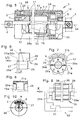
- Embodiment 1 ( Fig. 2 and 5 ) with the roller 5 has a mounted on a stationary on the frame 2 rod 6, are received on the bearings 7, 8 in the form of deep groove ball bearings. Their outer rings are received in lids 9, 10 by a tight fit. According to Fig. 5 the rod 6 in the frame 2 by a screw connection (not labeled) axially and radially fixed.
- the covers 9, 10 are pressed firmly with the ends of a tubular roller shell 11.
- an end 12 of a tube is attached to the lid 9.
- the tube is hereinafter referred to as eddy current transducer 13.
- eddy current transducer 13 Through the rod 6, an axis 14 extends.
- the free end of the eddy current transducer 13 extends into the vicinity of a support 15 which is combined with the rod 6 to form a component.
- the carrier 15 is made as a die-cast part of non-magnetizable material such as an aluminum-zinc alloy and the rod 6 rotatably and positively comprises.
- the carrier 15 is formed on an end face 16 with two mutually axially displaced end-side halves and two diametrically extending surfaces connecting them.
- end face 16 reference is made to the end of a permanent magnet to be described below.
- the carrier 15 is provided with a concentric with the axis 4 formed cylindrical shell 19, on which one end 20 of a shielding tube 21 made of ferromagnetic material such as steel is made.
- the roller shell 11, the shielding tube 21, and the eddy current sensor 13 form essential components of an eddy current brake 22.
- the inner bore (not labeled) of the roll mantle 11 and the mantle of the eddy current pickup 13 define therebetween an annular space 23.
- the wall thickness of the shielding tube 21 and the intermediate space 23 are dimensioned such that two annular air gaps a and b are formed.
- a gap 24 is formed between the shielding tube 21 and a permanent magnet 25 received on the rod 6.
- the permanent magnet 25 is formed with a bore 26, which allows the permanent magnet 25 is pushed free of play on the rod 6.
- the gap 24 is dimensioned such that between the permanent magnet 25 and the eddy current transducer 13 an annular air gap c is formed.
- the permanent magnet 25 has a left end side 27 and a right end side 28.
- the left end face 27 is formed with two end-side halves 29 and 29a, which are axially offset by a distance e to each other and thereby form two mutually aligned surfaces 30, 30a.
- the right end face 28 is formed, which corresponds geometrically to the end face rotated by 180 degrees in the sense of rotation of the clockwise about an axis X. It is further stated that the design of the end face 16 on the carrier 15 corresponds to the design of the left end side 27.
- the permanent magnet 25 is magnetized in the form of "8-pole, N- and S-pole alternately outside", the north pole N and the south pole S being symmetrically aligned with respect to the axis X, also with respect to the surfaces 30, 30a , It follows that the permanent magnet 25 regardless of its position with the end face 16 or the end face 27 can be brought to bear against the carrier 15 for conditioning.
- Fig. 7 shows a field line 31 a a course through air, so if there is no ferromagnetic material in the vicinity.
- a field line 31 b assumes a deflected course, when in the vicinity of ferromagnetic material such as the shielding tube 21 is located.
- the field line 31 b extends through the eddy current carrier 13, in which thus eddy currents.
- the field line 31 b is shown as a self-contained line.
- Embodiment 2 ( Fig. 3 ) has a roller 5a, which corresponds in its construction with the exception of the rod 6 of the roller 5. Deviating from this, the roller 5a is mounted on two rod parts 6a, 6b, which are each firmly clamped to the frame 2. At their free ends, the rod parts 6a, 6b are fixedly connected to the carrier 15 and the end piece 32, which receive the permanent magnet 25 between them.
- Embodiment 3 ( Fig. 4 ) has a roller 5b.
- a support 15a is rotatably provided, which are formed at its end faces 16a and 27a, respectively as said end faces 16 and 27.
- the carrier 15a is located approximately in the middle of the longitudinal extension of the roller shell 11 fixed to the rod 6.
- a shielding tube 21a is fixedly connected, which corresponds in diameter and with respect to the material of said shielding tube 21. Further, the shielding tube 21 a extends as a one-piece component via the side of the support 15a arranged permanent magnets 25, 25a, 25b. These correspond in their structure, apart from the different lengths of the permanent magnets 25a and 25b described the permanent magnet 25.
- the permanent magnets 25a, 25b as described frontally rotatably and axially fixed to the rod 6. With the differently long trained permanent magnets 25, 25a, 25b different strength permanent magnets are provided which allow an adjustment of the desired total braking torque of the eddy current brakes 22 and 22a.
- Embodiment 4 instead of the permanent magnet, an electromagnet 35 is provided which corresponds in its dimensions to that of the permanent magnet 25 described above.
- Fig. 10 36 poles are formed similar to an electric motor to an armature, which are known to form north poles N and south poles S of the electromagnet 35 as a result of DC windings 37.
- the armature 36 is closed at the end with lids 38, 39.
- the lid 38 is formed on an end face 27a corresponding to the end face 27 and the lid 39 with one of the end face 28a corresponding to the end face 28.
- the supply of direct current via an electrical circuit 40, which has a variable resistor 41 for changing the windings 37 flowing through the current.
- the roller 5 instead of the permanent magnet 25 may be equipped with the solenoid 35.
- the described operation applies equally to the embodiments 2 to 4.
- the embodiment 4 allows the winding of the electromagnet 35 acting upon current and thus the strength of the braking torque to the specific application of the role 5 adapt accordingly.
Landscapes
- Engineering & Computer Science (AREA)
- Mechanical Engineering (AREA)
- Dynamo-Electric Clutches, Dynamo-Electric Brakes (AREA)
Description
- Die Erfindung betrifft eine Rolle mit einer Wirbelstrombremse nach dem Oberbegriff von Anspruch 1.
- Eine derartige Rolle ist aus der
EP 1 243 528 A1 bekannt, die im Innern eines äußeren Rohres eine Bremseinrichtung in Form einer Wirbelstrombremse aufweist. Hierzu ist das äußere Rohr, also der Rollenmantel auf seiner Innenfläche mit einem Einsatzkörper aus elektrisch gut leitfähigem Material wie Kupfer oder Aluminium ausgebildet. Der Rollenmantel ist drehbar auf einer Stange gelagert, die in einem ortsfesten Gestell befestigt ist. Auf der Stange sind fest angeordnete Dauermagnete mit Polen angeordnet, die sich im Abstand eines Luftspaltes zu dem Einsatzkörper befinden. Bei einer Drehung des Rollenmantels gemeinsam mit dem Einsatzkörper relativ zu den ortsfesten Polen werden in dem Einsatzkörper durch das Magnetfeld Wirbelströme induziert, die der Drehbewegung des Rollenmantels ein Bremsmoment entgegensetzen, welches mit steigender Drehzahl zunimmt. - Zu diesem, nachfolgend als erstes Bremsmoment bezeichnet, addiert sich ein zweites Bremsmoment hinzu, wenn das Magnetfeld ebenso Wirbelströme in dem aus elektrisch leitendem, nicht magnetisierbarem Werkstoff wie beispielsweise Aluminium, oder Edelstahl gefertigten Rollenmantel verursacht. Wenn der Rollenmantels außerdem aus magnetisierbarem Werkstoff wie beispielsweise Stahl hergestellt ist, kommt es weiter zu einer Einwirkung des Magnetfelds auf den Rollenmantel infolge seiner Drehung um das ortsfeste Magnetfeld zu einer stetigen Ummagnetisierung, womit ein drittes Bremsmoment auftritt.
- Die Verwendung einer derartigen Rolle erfolgt an einer Rollenbahn, die mit einer Mehrzahl von Rollen ohne jegliche Bremseinrichtung ausgestattet ist und mit einer leicht geneigten Förderstrecke verläuft. Das Fördern von darauf aufliegendem Fördergut erfolgt ohne weiteren Antrieb durch die vom Eigengewicht verursachte Hangabtriebskraft. Im Betrieb solcher Rollenbahn kann es aus verschiedenen Gründen zu einem Stillstand des Förderguts kommen, so dass sich das Fördergut ohne freien Zwischenraum zwischen einzelnen Fördergut-Teilen aufstaut. Sobald dann der Weitertransport des Förderguts wieder einsetzt, ist es erforderlich, dass sich das Fördergut selbständig wieder auf der geneigten Förderstrecke in Bewegung setzt. Der erläuterte Sachverhalt führt zu der Schwierigkeit, einerseits ein selbsttätiges Abrollen des Förderguts auf der Rollenbahn durch die geneigte Förderstrecke zu erreichen, andererseits aber zu vermeiden, dass das Fördergut eine unangemessene größere Geschwindigkeit annimmt. Zur Kontrolle der Fördergut-Geschwindigkeit ist bekannt, in der Rollenbahn an geeigneten Positionen Rollen mit eingebauten Bremsen mechanischer oder elektrischer Bauart ähnlich einem Elektromotor oder als Wirbelstrombremsen einzusetzen.
- Bei dem Einsatz der bekannten Rolle mit einer Wirbelstrombremse muss in Kauf genommen werden, dass ein selbsttätiges Anfahren von zuvor gestopptem Förderguts nur durch Inkaufnahme einer stärkeren Neigung der Förderbahn erreicht werden kann, woraus wiederum größere Energien abzufangen sind, wenn sich Fördergut aufstaut.
- Aus der
DE 28 21 973 A1 ist eine magnetische Drehmomentkupplung bekannt, bei der Wirbelströme infolge von relativen Bewegungen von stationären Dauermagneten zu einem Wirbelstromträger und auch Ummagnetisierungen an Bauteilen zu einer erwünschten Drehmomentübertragung genutzt werden. Die Druckschrift ist lediglich hinsichtlich der tassenförmig ausgebildeten Kupplungsteile von Interesse. - Zum Stand der Technik über Dauermagnete, Magnetismus und Wirbelstrombremsen wird auf das Lehrbuch "Europa-Lehrmittel, ELEKTRONIK, 1. Teil: Grundlagen-Elektronik 3. Auflage", Seiten 73 bis 75 und Seiten 96 und 97 verwiesen.
- Der Erfindung liegt die Aufgabe zugrunde, eine zu niedrigen Kosten herzustellende Weiterbildung der bekannten Rolle mit einer Wirbelstrombremse anzugeben, die dem Anlaufen der Rolle einen kleinstmöglichen Widerstand entgegensetzt und die Wirksamkeit der Wirbelstrombremse erhöht.
- Die Lösung dieser Aufgabe erfolgt bei der Rolle nach dem Oberbegriff von Anspruch 1 durch dessen kennzeichnende Merkmale.
Die Ausgestaltung der Wirbelstrombremse mit einem festen, relativ zu dem stationären Magnetfeld unbewegbaren Abschirmrohr aus ferromagnetischem Material führt einerseits dazu, ein Bremsmoment infolge einer stetigen Ummagnetisierung auszuschalten und andererseits dazu, das von dem Dauermagneten ausgehende Magnetfeld einzig für die Wirbelstrombremse zu nutzen. Dies führt dazu, dass das zu Beginn einer Drehung des Rollenmantels entgegenstehende Bremsmoment von dem Wert Null durch die beginnende Drehung mit der Wirkung des Wirbelstroms ansteigt. Somit wird das Anlaufen des Rollenmantels erleichtert. - Ein weiterer Vorteil ergibt sich daraus, dass mit dem ferromagnetischen Abschirmrohr die Rolle ungeachtet des für den Rollenmantel verwendeten Werkstoffs ein Ausbreiten von magnetischer Emission verhindert wird.
- Schließlich führt die Anordnung des Abschirmrohres zu dem weiteren Vorteil, dass mit Ausnahme von Anforderungen an eine gewisse Festigkeit keinerlei Anforderungen an den Werkstoff des Rollenmantels erfüllt sein müssen. Daraus ergeben sich Vorteile für einen trägheitsarmen und zu niedrigen Kosten herzustellenden Rollenmantel, wie dies beispielsweise durch die Verwendung von Kunststoff erreicht werden kann.
- Mit den Merkmalen der Ansprüche 2 bis 5 werden vorteilhafte Weiterbildungen angegeben. Das Merkmal von Anspruch 6 führt zu einer vorteilhaften Raumausnutzung und zu weiteren Gestaltungsmöglichkeiten für den Magneten. Eine Kosten sparende und kompakte Bauweise wird mit den Merkmalen von Anspruch 7 erzielt. Eine weitere vorteilhafte Weiterbildung wird mit dem Merkmal von Anspruch 8 erzielt. Die Merkmale der Ansprüche 9 und 10 ermöglichen, das Bremsmoment der Wirbelstrombremse den Einsatzbedingungen anzupassen.
- Weitere Merkmale, Vorteile und Einzelheiten der Erfindung ergeben sich aus der folgenden Beschreibung von Ausführungsbeispielen anhand der Zeichnung.
- Es zeigt
- Fig. 1
- eine Rollenbahn mit Fördergut,
- Fig. 2
- eine schematisch Darstellung der Rolle eines Ausführungsbeispiels 1,
- Fig. 3
- eine schematisch Darstellung der Rolle eines Ausführungsbeispiels 2,
- Fig. 4
- eine schematisch Darstellung der Rolle eines Ausführungsbeispiels 3,
- Fig. 5
- eine Halbschnitt-Ansicht der ausgeführten Rolle,
- Fig. 6
- ein Bauteil aus der Rolle gemäß
Fig. 5 , - Fig. 7
- eine Ansicht des Bauteils in Richtung des Sichtpfeils VII in
Fig. 6 , - Fig. 8
- einen Ausschnitt einer Weiterbildung von Bauteilen gemäß
Fig. 5 in verkleinertem Maßstab, - Fig. 9
- eine Weiterbildung des Magneten als Elektromagnet in einer der
Fig. 5 entsprechenden Ansicht und - Fig. 10
- eine Ansicht auf eine Stirnseite des Elektromagneten gemäß dem Sichtpfeil X in
Fig. 9 . - In
Fig. 1 ist eine Rollenbahn 1 mit einem ortfesten Gestell 2 dargestellt, an dem eine Mehrzahl von Rollen 3 fest angeordnet sind, die eine geneigte Förderstrecke bilden. Die Rollen 3 sind frei ohne einen Antrieb oder eine Bremse ausgeführt und unterstützen ein darauf aufliegendes Fördergut 4, welches danach trachtet, durch sein Gewicht auf der Förderstrecke herabzurollen. Weiter ist an der Rollenbahn 1 eine erfindungsgemäße Rolle 5 mit einer Wirbelstrombremse angeordnet. - Das Ausführungsbeispiel 1 (
Fig. 2 und5 ) mit der Rolle 5 weist eine auf einer ortsfest an dem Gestell 2 befestigte Stange 6 auf, auf der Lager 7, 8 in Form von Rillenkugellagern aufgenommen sind. Deren Außenringe sind in Deckeln 9, 10 durch festen Sitz aufgenommen. GemäßFig. 5 ist die Stange 6 in dem Gestell 2 durch eine Schraubenverbindung (nicht bezeichnet) achsial und radial festgelegt. - Die Deckel 9, 10 sind fest mit Enden eines röhrförmigen Rollenmantel 11 verpresst. In konzentrischer Anordnung mit der Stange 6 und dem Rollenmantel 11 ist an dem Deckel 9 ein Ende 12 eines Rohres befestigt. Das Rohr wird nachfolgend als Wirbelstrom-Aufnehmer 13 bezeichnet. Durch die Stange 6 erstreckt sich eine Achse 14.
- Das freie Ende des Wirbelstrom-Aufnehmers 13 erstreckt sich bis in die Nähe eines Trägers 15, der mit der Stange 6 zu einem Bauteil vereint ist. Hierzu ist der Träger 15 als Druckgussteil aus nicht magnetisierbarem Werkstoff wie beispielsweise eine Aluminium-Zink-Legierung hergestellt ist und die Stange 6 drehfest und formschlüssig umfasst. Der Träger 15 ist an einer Stirnseite 16 mit zwei zueinander axial verschobenen Stirnseiten-Hälften und zwei sie verbindenden diametral verlaufenden Flächen ausgebildet. Für Einzelheiten der Stirnseite 16 wird auf die nachfolgend noch zu beschreibende Stirnseite eines Dauermagneten verwiesen.
- Weiter ist der Träger 15 mit einem konzentrisch zu der Achse 4 ausgebildeten zylindrischen Mantel 19 vorgesehen, auf dem ein Ende 20 eines Abschirmrohres 21 aus ferromagnetischem Werkstoff wie beispielsweise Stahl hergestellt ist. Der Rollenmantel 11, das Abschirmrohr 21, und der Wirbelstrom-Aufnehmer 13 bilden wesentliche Bauteile einer Wirbelstrombremse 22.
- Mit der Anordnung begrenzen die Innenbohrung (nicht bezeichnet) des Rollenmantels 11 und der Mantel des Wirbelstrom-Aufnehmers 13 zwischen sich einen kreisringringförmigen Zwischenraum 23. In diesen ragt das freie Ende des Abschirmrohres 21 bis in die Nähe des Deckels 9 hinein. Die Wandstärke des Abschirmrohrs 21 und der Zwischenraum 23 sind derart bemessen, dass zwei kreisringförmige Luftspalten a und b ausgebildet sind.
- Weiter ist ein Zwischenraum 24 zwischen dem Abschirmrohr 21 und einem Dauermagneten 25 ausgebildet, der auf der Stange 6 aufgenommen ist.
Der Dauermagnet 25 ist mit einer Bohrung 26 ausgebildet, die ermöglicht, dass der Dauermagnet 25 spielfrei auf die Stange 6 aufschiebbar ist. Der Zwischenraum 24 ist derart bemessen, dass zwischen dem Dauermagnet 25 und dem Wirbelstrom-Aufnehmer 13 ein kreisringförmiger Luftspalt c ausgebildet ist. - Der Dauermagnet 25 weist eine linke Stirnseite 27 und eine rechte Stirnseite 28 auf. Die linke Stirnseite 27 ist mit zwei Stirnseiten-Hälften 29 und 29a ausgebildet, die axial um einen Abstand e zueinander versetzt sind und hierdurch zwei miteinander fluchtende Flächen 30, 30a ausbilden. In gleicher Weise ist die rechte Stirnseite 28 ausgebildet, die geometrisch der um 180 Grad im Drehsinn des Uhrzeigers um eine Achse X gedrehten Stirnseite 27 entspricht. Weiter wird angegeben, dass die Gestaltung der Stirnseite 16 an dem Träger 15 der Gestaltung der linken Stirnseite 27 entspricht.
- Gemäß
Fig. 7 ist der Dauermagnet 25 in der Form "8-polig, N- und S-Pol wechselweise außen" magnetisiert, wobei die Nordpole N und die Südpole S in Bezug auf die Achse X, ebenso in Bezug auf die Flächen 30, 30a symmetrisch ausgerichtet sind. Hieraus folgt, dass der Dauermagnet 25 ungeachtet seiner Lage mit der Stirnseite 16 oder der Stirnseite 27 zur Anlage an dem Träger 15 zur Anlage gebracht werden kann. - Zwischen den Polen N, S stellen sich gedanklich magnetische Feldlinien ein. Diese verlaufen außerhalb des Magneten vom Nordpol N zum Südpol S, innerhalb vom Südpol S zum Nordpol N und bilden einen geschlossenen Verlauf. Die Feldlinien nehmen je nach ihrer Umgebung durch Luft oder durch ferromagnetisches Material unterschiedliche Verläufe ein. In
Fig. 7 zeigt eine Feldlinie 31 a einen Verlauf durch Luft, wenn sich also in der Nähe kein ferromagnetisches Material befindet. Im Gegensatz dazu nimmt eine Feldlinie 31 b einen abgelenkten Verlauf ein, wenn sich in der Nähe ferromagnetisches Material wie das Abschirmrohr 21 befindet. Dabei verläuft die Feldlinie 31 b durch den Wirbelstrom-Träger 13, in dem damit Wirbelströme entstehen. Weiter ist die Feldlinie 31 b als eine in sich geschlossene Linie dargestellt. - Mit der Gestaltung der Stirnseite 16 an dem Träger 15, der Stirnseiten 27, 28 an dem Dauermagnet 25 und einer der Stirnseite 28 entsprechenden Stirnseite 28a an einem Endstück 32 wird erreicht, dass der Dauermagnet 25 mit dem Träger 15 formschlüssig nach Art einer Klauenkupplung ineinander greifend festgelegt ist. Weiter erfolgt eine axiale Festlegung der Stange 6 mit dem Träger 15 und der darauf aufgenommenen Bauteile wie der Dauermagnet 25 und das Endstück 32 durch den Rollenmantel 11 mit den die Lager 7, 8 aufnehmenden Deckeln 9, 10.
- Hinsichtlich der verwendeten Werkstoffe wird angegeben, dass
- der Rollenmantel 11 ein Rohr aus einem beliebigen Werkstoff wie Stahl, Aluminium oder Kunststoff beispielsweise mit einer Wandstärke von 2 bis 5 Millimeter,
- die Abschirmrohre 21, 21a aus magnetisierbarem Werkstoff wie Stahl einer bestimmten Sorte mit guter Leitfähigkeit für magnetische Feldlinien,
- und die Wirbelstrom-Aufnehmer 13, 13a aus elektrisch gut Strom leitendem, nicht magnetisierbarem Werkstoff wie Kupfer oder Aluminium mit einer Wandstärke von beispielsweise 3 Millimeter hergestellt sind.
- Das Ausführungsbeispiel 2 (
Fig. 3 ) weist eine Rolle 5a auf, die in ihrem Aufbau mit Ausnahme der Stange 6 dem der Rolle 5 entspricht. Abweichend davon ist die Rolle 5a auf zwei Stangenteilen 6a, 6b gelagert, die jeweils fest an dem Gestell 2 eingespannt sind. An ihren freien Enden sind die Stangenteile 6a, 6b fest mit dem Träger 15 und dem Endstück 32 verbunden, die zwischen sich den Dauermagneten 25 aufnehmenden. - Das Ausführungsbeispiel 3 (
Fig. 4 ) weist eine Rolle 5b auf. Auf der Stange 6 ist drehfest ein Träger 15a vorgesehen, der an seinen Stirnseiten 16a und 27a jeweils wie die genannten Stirnseiten 16 und 27 ausgebildet sind. Der Träger 15a befindet sich etwa in der Mitte der Längserstreckung des Rollenmantels 11 fest auf der Stange 6. An dem Träger 15a ist ein Abschirmrohr 21 a fest verbunden, welches im Durchmesser und hinsichtlich des Werkstoffs dem genannten Abschirmrohr 21 entspricht. Weiter erstreckt sich das Abschirmrohr 21 a als einteiliges Bauteil über die seitlich des Trägers 15a angeordneten Dauermagnete 25, 25a, 25b. Diese entsprechen in ihrem Aufbau, abgesehen von den unterschiedlichen Längen der Dauermagnete 25a und 25b dem beschriebenen Dauermagnet 25. Wie dieser sind die Dauermagneten 25a, 25b wie beschrieben stirnseitig drehfest und axial auf der Stange 6 festgelegt. Mit den unterschiedlich lang ausgebildeten Dauermagneten 25, 25a, 25b werden unterschiedlich starke Dauermagneten bereitgestellt, die eine Anpassung des gewünschten Gesamt-Bremsmoments der Wirbelstrombremsen 22 und 22a ermöglichen. - Das Ausführungsbeispiel 4 (
Fig. 9 u. 10) ist anstatt des Dauermagneten ein Elektromagnet 35 vorgesehen, der in seinen Abmessungen denen des vorstehend beschriebenen Dauermagneten 25 entspricht. GemäßFig. 10 sind ähnlich einem Elektromotor an einem Anker 36 Pole ausgebildet, die infolge von mit Gleichstrom beaufschlagten Wicklungen 37 bekanntlich Nordpole N und Südpole S des Elektromagneten 35 bilden. Der Anker 36 ist stirnseitig mit Deckeln 38, 39 verschlossen. Der Deckel 38 ist an einer Stirnseite 27a entsprechend der Stirnseite 27 und der Deckel 39 mit einer der Stirnseite 28a entsprechend der Stirnseite 28 ausgebildet. Die Versorgung mit Gleichstrom erfolgt über eine elektrische Schaltung 40, die einen Stellwiderstand 41 zur Veränderung des die Wicklungen 37 durchflutenden Stromes aufweist. - Mit der Gestaltung des Elektromagneten 35 einschließlich der dem Dauermagnet 25 entsprechenden Stirnseiten 27a, 28a kann die Rolle 5 anstatt des Dauermagneten 25 mit dem Elektromagnet 35 ausgestattet sein.
- Die Arbeitsweise der Rolle 5 ist wie folgt:
- Mit dem im Stillstand auf der Rolle 5 aufliegenden Fördergut 4 befindet sich die Rolle 5 in einem Zustand, in dem der Rollenmantel 11 frei von jeglichem Bremsmoment ist. Sobald das Hindernis für die Bewegung des Förderguts 4 auf der Rollenbahn 1 aufgehoben ist, wirkt die von dem Eigengewicht des Förderguts 4 hervorgerufene Hangabtriebskraft und beginnt eine Weiterbewegung des Förderguts 4 und damit die Drehung des Rollenmantels 11 gemeinsam mit dem Wirbelstrom-Aufnehmer 13. Hiermit bewegt sich der Wirbelstrom-Aufnehmer 13 durch das von den Dauermagneten 23 erzeugte Magnetfeld, so dass eine Induzierung von Wirbelstrom in dem Wirbelstrom-Aufnehmer 13 erreicht wird und ein Bremsmoment auf den Rollenmantel 11 ausübt. Ausgehend von Stillstand des Rollenmantels 11 steigt das Bremsmoment damit von einem Wert Null stetig mit zunehmender Drehzahl des Rollenmantels 11 an.
- Infolge der Wirkung des stationären, aus magnetischem Stahl gefertigten Abschirmrohres 18, 32 wird eine Ummagnetisierung, also eine Wirkung des von dem ebenso stationären Dauermagneten 25 ausgehenden Magnetfeldes auf den Rollenmantel 11 ausgeschaltet. Damit sind definierte Verhältnisse geschaffen, so dass dem Anlaufen des Rollenmantels 11 anfangs kein Bremsmoment, mit zunehmender Drehzahl aber ein stetig ansteigendes Bremsmoment von der Wirbelstrombremse 13 entgegensteht. Dies bedeutet für die Rollenbahn 1, dass sie mit einer geringen Neigung ausgeführt werden kann und ein Aufstauen von lückenlos aneinander stoßenden Teilen des Förderguts 4 mit geringeren Massenkräften infolge verminderter Fördergeschwindigkeiten erfolgt.
- Die geschilderte Arbeitsweise gilt gleichermaßen für die Ausführungsbeispiele 2 bis 4. Das Ausführungsbeispiel 4 gestattet, den die Wicklung des Elektromagneten 35 beaufschlagenden Strom und damit die Stärke des Bremsmoments dem spezifischen Einsatzfall der Rolle 5 entsprechend anzupassen.
Bezugszeichenverzeichnis: 1 Rollenbahn 26 Bohrung 2 Gestell 27 27a linke Stirnseite 3 Rolle 28 rechte Stirnseite 4 Fördergut 29 29b Stirnseiten-Hälfte 5 5a, 5b Rolle mit 30 30a Fläche Wirbelstrombremse 31 31a Feldlinie 6 6a, 6b Stange 32 Endstück 7 Lager 33 -- 8 dto. 34 -- 9 9a Deckel 35 Elektromagnet 10 dto. 36 Anker 11 Rollenmantel 37 Wicklung 12 Ende 38 Deckel 13 13a Wirbelstrom-Aufnehmer 39 dto. 14 Achse 40 Schaltung 15 15a Träger 41 Stellwiderstand 16 16a Stirnseite 17 -- 18 -- N Nordpol 19 Mantel S Südpol 20 Ende 21 21 a Abschirmrohr a Luftspalt 22 22a 22b Wirbelstrombremse b dto. 23 Zwischenraum c dto. 24 dto. 25 25a, 25b Dauermagnet e Abstand X Achse
Claims (10)
- Rolle (5;5a;5b) mit folgenden Merkmalen:- ein rohrförmiger Rollenmantel (11;29) der in einer ortsfesten Lagerung (7,8) um eine Achse (14) drehbar gelagert ist,- eine Wirbelstrombremse (26) mit einem innerhalb des Rollenmantels (11) fest mit diesem verbundenen rohrförmigen Wirbelstrom-Aufnehmer (13;13a,13b) und mit einem ortsfest mit der Lagerung (7,8) verbundenen Magneten (25;25a;25b;35), mit im Abstand eines Luftspalts (c) zu dem Wirbelstrom-Aufnehmer (13;13a) angeordneten Nord- und Südpolen (N, S), dadurch gekennzeichnet, dass- zwischen dem Rollenmantel (11) und dem Wirbelstrom-Aufnehmer (13;13a) ein aus ferromagnetischem Werkstoff, z.B. Stahl, gefertigtes Abschirmrohr (21;21a) hineinragend ausgebildet ist,- das Abschirmrohr (21;21a) fest an einem Ende mit der ortsfesten Lagerung (7,8) verbunden ist,- das Abschirmrohr (21 ;21a) im Abstand eines zweiten Luftspalts (a) zu dem Rollenmantel (11) und im Abstand eines dritten Luftspalts (b) zu dem Wirbelstrom-Aufnehmer (13;13a) angeordnet ist- wobei der zweite (a) und der dritte Luftspalt (b) derart ausreichend groß bemessen sind, dass eine Berührung des Rollenmantels (11) und des Wirbelstrom-Aufnehmers (13;13a) mit dem ortsfesten Abschirmrohr (21;21a) bei Ausführung der Drehung ausgeschlossen ist.
- Rolle (5;5a, 5b) nach Anspruch 1, dadurch gekennzeichnet, dass der Magnet (25;25a;25b;35) an einer seiner Stirnseiten (27,28) formschlüssig mit der ortsfesten Lagerung (7,8) verbunden ist.
- Rolle (5;5a, 5b) nach Anspruche 1 oder 2, dadurch gekennzeichnet, dass der Magnet als Dauermagnet (25,25a,25b) ausgebildet ist.
- Rolle (5;5a, 5b) nach einem der Ansprüche 1 bis 3, dadurch gekennzeichnet, dass mehrere des Magneten (25,25a,25b) vorgesehen sind.
- Rolle (5;5a;5b) nach einem der vorangehenden Ansprüche, dadurch gekennzeichnet, dass sich die Achse (14) durch eine ortsfest angeordnete Stange (6) erstreckt.
- Rolle (5;5a;5b) nach Anspruch 5, dadurch gekennzeichnet, dass die Stange (6) zwei voneinander getrennte, konzentrisch zueinander festgelegte Stangenteile (6a,6b) aufweist..
- Rolle (5;5a;5b) nach einem der vorangehenden Ansprüche, dadurch gekennzeichnet, dass benachbart angeordnete Wirbelstrombremsen (22,22a,22b) ein gemeinsames Abschirmrohr (21a) aufweisen, welches fest mit einem auf der Stange (6) oder mindestens einem der Stangenteile (6a,6b) befestigten Träger (15a) verbunden ist.
- Rolle (5;5a;5b) nach Anspruch 7, dadurch gekennzeichnet dass der Träger (15a) zwischen zwei Wirbelstrombremsen (22,22a) angeordnet ist.
- Rolle (5;5a, 5b) nach einem der Ansprüche 1 bis 3, dadurch gekennzeichnet, dass der Magnet als Elektromagnet (35) ausgebildet ist.
- Rolle nach Anspruch 9,
dadurch gekennzeichnet, dass der Elektromagnet (35) mit einer elektrischen Schaltung (40) verbunden ist, die einen Stellwiderstand (41) aufweist.
Priority Applications (1)
| Application Number | Priority Date | Filing Date | Title |
|---|---|---|---|
| PL13747349T PL2922775T3 (pl) | 2013-07-18 | 2013-07-18 | Rolka z hamulcem elektrowirowym |
Applications Claiming Priority (1)
| Application Number | Priority Date | Filing Date | Title |
|---|---|---|---|
| PCT/EP2013/002134 WO2015007299A1 (de) | 2013-07-18 | 2013-07-18 | Rolle mit einer wirbelstrombremse |
Publications (2)
| Publication Number | Publication Date |
|---|---|
| EP2922775A1 EP2922775A1 (de) | 2015-09-30 |
| EP2922775B1 true EP2922775B1 (de) | 2016-09-28 |
Family
ID=48949113
Family Applications (1)
| Application Number | Title | Priority Date | Filing Date |
|---|---|---|---|
| EP13747349.2A Active EP2922775B1 (de) | 2013-07-18 | 2013-07-18 | Rolle mit einer wirbelstrombremse |
Country Status (7)
| Country | Link |
|---|---|
| US (1) | US9415937B2 (de) |
| EP (1) | EP2922775B1 (de) |
| CN (1) | CN104603033B (de) |
| DK (1) | DK2922775T3 (de) |
| ES (1) | ES2600753T3 (de) |
| PL (1) | PL2922775T3 (de) |
| WO (1) | WO2015007299A1 (de) |
Cited By (11)
| Publication number | Priority date | Publication date | Assignee | Title |
|---|---|---|---|---|
| DE102017010091A1 (de) | 2017-10-31 | 2019-05-02 | Günther Zimmer | Werkstücktransportsystem mit abbremsbaren Transporträdern oder Transportrollen |
| DE102021106255B3 (de) | 2021-03-15 | 2022-06-15 | Interroll Holding Ag | Förderanordnung |
| WO2022194738A2 (de) | 2021-03-16 | 2022-09-22 | Interroll Holding Ag | Förderanordnung |
| DE102021106398A1 (de) | 2021-03-16 | 2022-09-22 | Interroll Holding Ag | Förderanordnung |
| DE102021006589A1 (de) | 2021-03-16 | 2022-10-06 | Interroll Holding Ag | Förderanordnung |
| DE102021123621A1 (de) | 2021-09-13 | 2023-03-16 | Interroll Holding Ag | Anordnung umfassend eine motorbetriebene Förderrolle sowie Förderer |
| US11643273B1 (en) | 2020-11-24 | 2023-05-09 | Milwaukee Electronics Corporation | Roller brake |
| WO2023174997A1 (en) | 2022-03-16 | 2023-09-21 | Interroll Holding Ag | Brake roller, roller conveyor and method of installation of a roller conveyor |
| WO2024194238A1 (en) | 2023-03-22 | 2024-09-26 | Interroll Holding Ag | Conveyor arrangement |
| EP4644297A1 (de) | 2024-04-29 | 2025-11-05 | Interroll Holding AG | Bremsförderrolle |
| WO2026074203A1 (de) | 2024-10-04 | 2026-04-09 | Interroll Holding Ag | Förderrutsche |
Families Citing this family (7)
| Publication number | Priority date | Publication date | Assignee | Title |
|---|---|---|---|---|
| US10836580B2 (en) | 2018-04-06 | 2020-11-17 | Intelligrated Headquarters, Llc | Conveyor cartridge with braking mechanism |
| DE102018215773B4 (de) * | 2018-09-17 | 2023-03-16 | Deutsche Post Ag | Adaptive Rollenbahn |
| US10472174B1 (en) * | 2018-11-26 | 2019-11-12 | Toyota Motor Engineering & Manufacturing North America, Inc. | Induced magnetic field tote transfer chimney and methods of use |
| RU198420U1 (ru) * | 2020-02-12 | 2020-07-06 | Закрытое акционерное общество "Инженерно-технический центр "КРОС" | Ролик тормозной магнитный для роликовых гравитационных конвейеров |
| FI129445B (en) * | 2021-02-11 | 2022-02-28 | Valmet Technologies Oy | Braking of an unpowered roller in a fiber web machine, especially in a roller cutting machine |
| NL2029249B1 (en) * | 2021-09-24 | 2023-03-30 | Vmi Holland Bv | Stitcher, tire building machine comprising said stitcher and method for stitching a tire component |
| JP7389163B2 (ja) * | 2022-03-31 | 2023-11-29 | 日本金銭機械株式会社 | 搬送システム |
Family Cites Families (10)
| Publication number | Priority date | Publication date | Assignee | Title |
|---|---|---|---|---|
| DE1278936B (de) * | 1964-07-08 | 1968-09-26 | Demag Zug Gmbh | Verzoegerungsvorrichtung fuer Laufrollen |
| JPS53146057A (en) | 1977-05-20 | 1978-12-19 | Vibrac Corp | Magnetic torque coupling |
| JPH08244931A (ja) * | 1995-03-15 | 1996-09-24 | Pabotsuto Giken:Kk | ローラコンベヤのブレーキ装置 |
| JPH08208011A (ja) * | 1995-11-14 | 1996-08-13 | Hakko Denki Kk | ローラコンベヤのブレーキローラ |
| AU781006C (en) * | 1999-11-02 | 2007-06-28 | Rollerbrake (Pty) Ltd. | Conveyor idler |
| EP1243528A1 (de) | 2001-03-21 | 2002-09-25 | Erhard Schmale | Bremsrolle einer Rollenbahn |
| NL1021991C2 (nl) * | 2002-11-26 | 2004-05-27 | Vanderlande Ind Nederland | Rollentransportbaan. |
| MX2007002827A (es) * | 2005-03-25 | 2007-04-27 | Yazaki Ind Chem Co Ltd | Transportador por gravedad de rueda o rodillo capaz de controlar el frenado con respecto a un objeto que esta siendo transportado. |
| EP2377783A1 (de) * | 2010-04-14 | 2011-10-19 | Interroll Holding AG | Förderrolle mit Fliehkraftbetätigter Magnetbremse. |
| ES2436515T3 (es) * | 2011-04-26 | 2014-01-02 | Interroll Holding Ag | Rodillo de frenado |
-
2013
- 2013-07-18 EP EP13747349.2A patent/EP2922775B1/de active Active
- 2013-07-18 DK DK13747349.2T patent/DK2922775T3/en active
- 2013-07-18 ES ES13747349.2T patent/ES2600753T3/es active Active
- 2013-07-18 US US14/421,575 patent/US9415937B2/en active Active
- 2013-07-18 PL PL13747349T patent/PL2922775T3/pl unknown
- 2013-07-18 WO PCT/EP2013/002134 patent/WO2015007299A1/de not_active Ceased
- 2013-07-18 CN CN201380041894.2A patent/CN104603033B/zh active Active
Cited By (15)
| Publication number | Priority date | Publication date | Assignee | Title |
|---|---|---|---|---|
| DE102017010091A1 (de) | 2017-10-31 | 2019-05-02 | Günther Zimmer | Werkstücktransportsystem mit abbremsbaren Transporträdern oder Transportrollen |
| US11643273B1 (en) | 2020-11-24 | 2023-05-09 | Milwaukee Electronics Corporation | Roller brake |
| DE102021106255B3 (de) | 2021-03-15 | 2022-06-15 | Interroll Holding Ag | Förderanordnung |
| WO2022194736A1 (de) | 2021-03-15 | 2022-09-22 | Interroll Holding Ag | Förderanordnung |
| DE102021106398B4 (de) | 2021-03-16 | 2022-11-17 | Interroll Holding Ag | Förderanordnung |
| DE102021006589A1 (de) | 2021-03-16 | 2022-10-06 | Interroll Holding Ag | Förderanordnung |
| DE102021106398A1 (de) | 2021-03-16 | 2022-09-22 | Interroll Holding Ag | Förderanordnung |
| WO2022194738A2 (de) | 2021-03-16 | 2022-09-22 | Interroll Holding Ag | Förderanordnung |
| DE102021006589B4 (de) | 2021-03-16 | 2023-10-12 | Interroll Holding Ag | Förderanordnung |
| DE202022003350U1 (de) | 2021-03-16 | 2026-02-20 | Interroll Holding Ag | Förderanordnung |
| DE102021123621A1 (de) | 2021-09-13 | 2023-03-16 | Interroll Holding Ag | Anordnung umfassend eine motorbetriebene Förderrolle sowie Förderer |
| WO2023174997A1 (en) | 2022-03-16 | 2023-09-21 | Interroll Holding Ag | Brake roller, roller conveyor and method of installation of a roller conveyor |
| WO2024194238A1 (en) | 2023-03-22 | 2024-09-26 | Interroll Holding Ag | Conveyor arrangement |
| EP4644297A1 (de) | 2024-04-29 | 2025-11-05 | Interroll Holding AG | Bremsförderrolle |
| WO2026074203A1 (de) | 2024-10-04 | 2026-04-09 | Interroll Holding Ag | Förderrutsche |
Also Published As
| Publication number | Publication date |
|---|---|
| WO2015007299A1 (de) | 2015-01-22 |
| PL2922775T3 (pl) | 2017-03-31 |
| DK2922775T3 (en) | 2016-12-12 |
| US20160145046A1 (en) | 2016-05-26 |
| CN104603033B (zh) | 2016-12-07 |
| EP2922775A1 (de) | 2015-09-30 |
| ES2600753T3 (es) | 2017-02-10 |
| CN104603033A (zh) | 2015-05-06 |
| US9415937B2 (en) | 2016-08-16 |
Similar Documents
| Publication | Publication Date | Title |
|---|---|---|
| EP2922775B1 (de) | Rolle mit einer wirbelstrombremse | |
| EP3180542B1 (de) | Magnetdämpfer für schwingungstilger | |
| DE1961846C3 (de) | Drehzahlgeber zur Bestimmung der Drehzahl oder Drehzahländerung von Fahrzeugrädern, insbesondere für Bremsschlupfregelanlagen von Kraftfahrzeugen | |
| DE102011075548B4 (de) | Lager mit einer Energieerfassungseinheit, insbesondere Pendelrollen-Lager zur Lagerung einer Walze | |
| CH703662A1 (de) | Inspektionsfahrzeug für die inspektion eines luftspalts zwischen dem rotor und dem stator eines generators. | |
| DE10358759A1 (de) | Aussenläufermotor mit stehender Lagerachse | |
| DE1912378A1 (de) | Foerdervorrichtungsaufbauten und dazugehoerige Drehkraft begrenzende UEbersetzungen | |
| EP2275701B1 (de) | Elektromagnetische Reibschaltkupplung | |
| DE102019206197A1 (de) | Expansionsventil | |
| EP2449277A1 (de) | Lager mit energieerzeugungseinheit | |
| EP2793243A2 (de) | Elektromagnetischer Aktuator | |
| EP1697054A1 (de) | Aussenläuferantrieb | |
| DE102012003499B4 (de) | Rolle mit einer Wirbelstrombremse | |
| DE202011106752U1 (de) | Bremsförderrolle | |
| DE1912976C3 (de) | Wälzlager für Längsbewegungen mit einer Kugelbüchse | |
| DE3011078C2 (de) | Magnetlager | |
| DE102010045539A1 (de) | Schwenkwinkelsensoranordnung | |
| DE102008040983A1 (de) | Sensorhalterung für ein Kolben-Zylinderaggregat | |
| DE102014018262A1 (de) | Signalgeberring für einen Magnetsensor und Gurtaufroller mit einem Signalgeberring | |
| DE2136187B2 (de) | Elektromotor | |
| EP3953619B1 (de) | Drehschieberventil für ein kraftfahrzeug | |
| DE3905216A1 (de) | Elektrisch steuerbare hysteresekupplung | |
| EP2881608B1 (de) | Deckelfester Zentralausrücker für eine hydraulische oder pneumatische Kupplungsbetätigungseinrichtung, insbesondere für ein Kraftfahrzeug | |
| DE4020275C2 (de) | Stellenantrieb zur Einstellung von zwei selbsthaltenden Lagen | |
| DE102005008794A1 (de) | Elektromotorischer Antrieb |
Legal Events
| Date | Code | Title | Description |
|---|---|---|---|
| PUAI | Public reference made under article 153(3) epc to a published international application that has entered the european phase |
Free format text: ORIGINAL CODE: 0009012 |
|
| 17P | Request for examination filed |
Effective date: 20141211 |
|
| AK | Designated contracting states |
Kind code of ref document: A1 Designated state(s): AL AT BE BG CH CY CZ DE DK EE ES FI FR GB GR HR HU IE IS IT LI LT LU LV MC MK MT NL NO PL PT RO RS SE SI SK SM TR |
|
| AX | Request for extension of the european patent |
Extension state: BA ME |
|
| GRAP | Despatch of communication of intention to grant a patent |
Free format text: ORIGINAL CODE: EPIDOSNIGR1 |
|
| DAX | Request for extension of the european patent (deleted) | ||
| INTG | Intention to grant announced |
Effective date: 20160429 |
|
| RBV | Designated contracting states (corrected) |
Designated state(s): AL AT BE BG CH CY CZ DK EE ES FI FR GB GR HR HU IE IS IT LI LT LU LV MC MK MT NL NO PL PT RO RS SE SI SK SM TR |
|
| REG | Reference to a national code |
Ref country code: DE Ref legal event code: R108 |
|
| GRAS | Grant fee paid |
Free format text: ORIGINAL CODE: EPIDOSNIGR3 |
|
| GRAA | (expected) grant |
Free format text: ORIGINAL CODE: 0009210 |
|
| RAP1 | Party data changed (applicant data changed or rights of an application transferred) |
Owner name: INTERROLL HOLDING AG |
|
| AK | Designated contracting states |
Kind code of ref document: B1 Designated state(s): AL AT BE BG CH CY CZ DK EE ES FI FR GB GR HR HU IE IS IT LI LT LU LV MC MK MT NL NO PL PT RO RS SE SI SK SM TR |
|
| REG | Reference to a national code |
Ref country code: GB Ref legal event code: FG4D Free format text: NOT ENGLISH |
|
| REG | Reference to a national code |
Ref country code: CH Ref legal event code: NV Representative=s name: LATSCHA SCHOELLHORN PARTNER AG, CH Ref country code: CH Ref legal event code: EP |
|
| REG | Reference to a national code |
Ref country code: AT Ref legal event code: REF Ref document number: 832542 Country of ref document: AT Kind code of ref document: T Effective date: 20161015 |
|
| REG | Reference to a national code |
Ref country code: IE Ref legal event code: FG4D Free format text: LANGUAGE OF EP DOCUMENT: GERMAN |
|
| REG | Reference to a national code |
Ref country code: NL Ref legal event code: FP |
|
| REG | Reference to a national code |
Ref country code: DK Ref legal event code: T3 Effective date: 20161208 |
|
| REG | Reference to a national code |
Ref country code: LT Ref legal event code: MG4D |
|
| PG25 | Lapsed in a contracting state [announced via postgrant information from national office to epo] |
Ref country code: FI Free format text: LAPSE BECAUSE OF FAILURE TO SUBMIT A TRANSLATION OF THE DESCRIPTION OR TO PAY THE FEE WITHIN THE PRESCRIBED TIME-LIMIT Effective date: 20160928 Ref country code: LT Free format text: LAPSE BECAUSE OF FAILURE TO SUBMIT A TRANSLATION OF THE DESCRIPTION OR TO PAY THE FEE WITHIN THE PRESCRIBED TIME-LIMIT Effective date: 20160928 Ref country code: HR Free format text: LAPSE BECAUSE OF FAILURE TO SUBMIT A TRANSLATION OF THE DESCRIPTION OR TO PAY THE FEE WITHIN THE PRESCRIBED TIME-LIMIT Effective date: 20160928 Ref country code: NO Free format text: LAPSE BECAUSE OF FAILURE TO SUBMIT A TRANSLATION OF THE DESCRIPTION OR TO PAY THE FEE WITHIN THE PRESCRIBED TIME-LIMIT Effective date: 20161228 Ref country code: RS Free format text: LAPSE BECAUSE OF FAILURE TO SUBMIT A TRANSLATION OF THE DESCRIPTION OR TO PAY THE FEE WITHIN THE PRESCRIBED TIME-LIMIT Effective date: 20160928 |
|
| REG | Reference to a national code |
Ref country code: ES Ref legal event code: FG2A Ref document number: 2600753 Country of ref document: ES Kind code of ref document: T3 Effective date: 20170210 |
|
| PG25 | Lapsed in a contracting state [announced via postgrant information from national office to epo] |
Ref country code: LV Free format text: LAPSE BECAUSE OF FAILURE TO SUBMIT A TRANSLATION OF THE DESCRIPTION OR TO PAY THE FEE WITHIN THE PRESCRIBED TIME-LIMIT Effective date: 20160928 Ref country code: SE Free format text: LAPSE BECAUSE OF FAILURE TO SUBMIT A TRANSLATION OF THE DESCRIPTION OR TO PAY THE FEE WITHIN THE PRESCRIBED TIME-LIMIT Effective date: 20160928 Ref country code: GR Free format text: LAPSE BECAUSE OF FAILURE TO SUBMIT A TRANSLATION OF THE DESCRIPTION OR TO PAY THE FEE WITHIN THE PRESCRIBED TIME-LIMIT Effective date: 20161229 |
|
| PG25 | Lapsed in a contracting state [announced via postgrant information from national office to epo] |
Ref country code: RO Free format text: LAPSE BECAUSE OF FAILURE TO SUBMIT A TRANSLATION OF THE DESCRIPTION OR TO PAY THE FEE WITHIN THE PRESCRIBED TIME-LIMIT Effective date: 20160928 Ref country code: EE Free format text: LAPSE BECAUSE OF FAILURE TO SUBMIT A TRANSLATION OF THE DESCRIPTION OR TO PAY THE FEE WITHIN THE PRESCRIBED TIME-LIMIT Effective date: 20160928 |
|
| PG25 | Lapsed in a contracting state [announced via postgrant information from national office to epo] |
Ref country code: IS Free format text: LAPSE BECAUSE OF FAILURE TO SUBMIT A TRANSLATION OF THE DESCRIPTION OR TO PAY THE FEE WITHIN THE PRESCRIBED TIME-LIMIT Effective date: 20170128 Ref country code: SM Free format text: LAPSE BECAUSE OF FAILURE TO SUBMIT A TRANSLATION OF THE DESCRIPTION OR TO PAY THE FEE WITHIN THE PRESCRIBED TIME-LIMIT Effective date: 20160928 Ref country code: SK Free format text: LAPSE BECAUSE OF FAILURE TO SUBMIT A TRANSLATION OF THE DESCRIPTION OR TO PAY THE FEE WITHIN THE PRESCRIBED TIME-LIMIT Effective date: 20160928 Ref country code: PT Free format text: LAPSE BECAUSE OF FAILURE TO SUBMIT A TRANSLATION OF THE DESCRIPTION OR TO PAY THE FEE WITHIN THE PRESCRIBED TIME-LIMIT Effective date: 20170130 Ref country code: BG Free format text: LAPSE BECAUSE OF FAILURE TO SUBMIT A TRANSLATION OF THE DESCRIPTION OR TO PAY THE FEE WITHIN THE PRESCRIBED TIME-LIMIT Effective date: 20161228 |
|
| REG | Reference to a national code |
Ref country code: FR Ref legal event code: PLFP Year of fee payment: 5 |
|
| PLBE | No opposition filed within time limit |
Free format text: ORIGINAL CODE: 0009261 |
|
| STAA | Information on the status of an ep patent application or granted ep patent |
Free format text: STATUS: NO OPPOSITION FILED WITHIN TIME LIMIT |
|
| 26N | No opposition filed |
Effective date: 20170629 |
|
| PG25 | Lapsed in a contracting state [announced via postgrant information from national office to epo] |
Ref country code: SI Free format text: LAPSE BECAUSE OF FAILURE TO SUBMIT A TRANSLATION OF THE DESCRIPTION OR TO PAY THE FEE WITHIN THE PRESCRIBED TIME-LIMIT Effective date: 20160928 |
|
| REG | Reference to a national code |
Ref country code: IE Ref legal event code: MM4A |
|
| PG25 | Lapsed in a contracting state [announced via postgrant information from national office to epo] |
Ref country code: IE Free format text: LAPSE BECAUSE OF NON-PAYMENT OF DUE FEES Effective date: 20170718 |
|
| REG | Reference to a national code |
Ref country code: BE Ref legal event code: MM Effective date: 20170731 |
|
| PG25 | Lapsed in a contracting state [announced via postgrant information from national office to epo] |
Ref country code: LU Free format text: LAPSE BECAUSE OF NON-PAYMENT OF DUE FEES Effective date: 20170718 |
|
| REG | Reference to a national code |
Ref country code: FR Ref legal event code: PLFP Year of fee payment: 6 |
|
| PG25 | Lapsed in a contracting state [announced via postgrant information from national office to epo] |
Ref country code: BE Free format text: LAPSE BECAUSE OF NON-PAYMENT OF DUE FEES Effective date: 20170731 |
|
| PG25 | Lapsed in a contracting state [announced via postgrant information from national office to epo] |
Ref country code: MT Free format text: LAPSE BECAUSE OF FAILURE TO SUBMIT A TRANSLATION OF THE DESCRIPTION OR TO PAY THE FEE WITHIN THE PRESCRIBED TIME-LIMIT Effective date: 20160928 |
|
| PG25 | Lapsed in a contracting state [announced via postgrant information from national office to epo] |
Ref country code: AL Free format text: LAPSE BECAUSE OF FAILURE TO SUBMIT A TRANSLATION OF THE DESCRIPTION OR TO PAY THE FEE WITHIN THE PRESCRIBED TIME-LIMIT Effective date: 20160928 |
|
| REG | Reference to a national code |
Ref country code: CH Ref legal event code: PCAR Free format text: NEW ADDRESS: GRELLINGERSTRASSE 60, 4052 BASEL (CH) |
|
| PG25 | Lapsed in a contracting state [announced via postgrant information from national office to epo] |
Ref country code: MC Free format text: LAPSE BECAUSE OF FAILURE TO SUBMIT A TRANSLATION OF THE DESCRIPTION OR TO PAY THE FEE WITHIN THE PRESCRIBED TIME-LIMIT Effective date: 20160928 Ref country code: HU Free format text: LAPSE BECAUSE OF FAILURE TO SUBMIT A TRANSLATION OF THE DESCRIPTION OR TO PAY THE FEE WITHIN THE PRESCRIBED TIME-LIMIT; INVALID AB INITIO Effective date: 20130718 |
|
| PG25 | Lapsed in a contracting state [announced via postgrant information from national office to epo] |
Ref country code: CY Free format text: LAPSE BECAUSE OF FAILURE TO SUBMIT A TRANSLATION OF THE DESCRIPTION OR TO PAY THE FEE WITHIN THE PRESCRIBED TIME-LIMIT Effective date: 20160928 |
|
| PG25 | Lapsed in a contracting state [announced via postgrant information from national office to epo] |
Ref country code: MK Free format text: LAPSE BECAUSE OF FAILURE TO SUBMIT A TRANSLATION OF THE DESCRIPTION OR TO PAY THE FEE WITHIN THE PRESCRIBED TIME-LIMIT Effective date: 20160928 |
|
| PGFP | Annual fee paid to national office [announced via postgrant information from national office to epo] |
Ref country code: NL Payment date: 20230720 Year of fee payment: 11 |
|
| PGFP | Annual fee paid to national office [announced via postgrant information from national office to epo] |
Ref country code: TR Payment date: 20230717 Year of fee payment: 11 Ref country code: IT Payment date: 20230731 Year of fee payment: 11 Ref country code: GB Payment date: 20230724 Year of fee payment: 11 Ref country code: ES Payment date: 20230821 Year of fee payment: 11 Ref country code: CZ Payment date: 20230707 Year of fee payment: 11 Ref country code: CH Payment date: 20230801 Year of fee payment: 11 Ref country code: AT Payment date: 20230718 Year of fee payment: 11 |
|
| PGFP | Annual fee paid to national office [announced via postgrant information from national office to epo] |
Ref country code: PL Payment date: 20230710 Year of fee payment: 11 Ref country code: FR Payment date: 20230724 Year of fee payment: 11 Ref country code: DK Payment date: 20230724 Year of fee payment: 11 |
|
| REG | Reference to a national code |
Ref country code: DK Ref legal event code: EBP Effective date: 20240731 |
|
| REG | Reference to a national code |
Ref country code: CH Ref legal event code: PL |
|
| REG | Reference to a national code |
Ref country code: NL Ref legal event code: MM Effective date: 20240801 |
|
| REG | Reference to a national code |
Ref country code: AT Ref legal event code: MM01 Ref document number: 832542 Country of ref document: AT Kind code of ref document: T Effective date: 20240718 |
|
| GBPC | Gb: european patent ceased through non-payment of renewal fee |
Effective date: 20240718 |
|
| PG25 | Lapsed in a contracting state [announced via postgrant information from national office to epo] |
Ref country code: NL Free format text: LAPSE BECAUSE OF NON-PAYMENT OF DUE FEES Effective date: 20240801 |
|
| PG25 | Lapsed in a contracting state [announced via postgrant information from national office to epo] |
Ref country code: CH Free format text: LAPSE BECAUSE OF NON-PAYMENT OF DUE FEES Effective date: 20240731 Ref country code: AT Free format text: LAPSE BECAUSE OF NON-PAYMENT OF DUE FEES Effective date: 20240718 |
|
| PG25 | Lapsed in a contracting state [announced via postgrant information from national office to epo] |
Ref country code: CZ Free format text: LAPSE BECAUSE OF NON-PAYMENT OF DUE FEES Effective date: 20240718 Ref country code: FR Free format text: LAPSE BECAUSE OF NON-PAYMENT OF DUE FEES Effective date: 20240731 |
|
| PG25 | Lapsed in a contracting state [announced via postgrant information from national office to epo] |
Ref country code: GB Free format text: LAPSE BECAUSE OF NON-PAYMENT OF DUE FEES Effective date: 20240718 |
|
| PG25 | Lapsed in a contracting state [announced via postgrant information from national office to epo] |
Ref country code: DK Free format text: LAPSE BECAUSE OF NON-PAYMENT OF DUE FEES Effective date: 20240731 |
|
| PG25 | Lapsed in a contracting state [announced via postgrant information from national office to epo] |
Ref country code: IT Free format text: LAPSE BECAUSE OF NON-PAYMENT OF DUE FEES Effective date: 20240718 |
|
| REG | Reference to a national code |
Ref country code: ES Ref legal event code: FD2A Effective date: 20250901 |
|
| PG25 | Lapsed in a contracting state [announced via postgrant information from national office to epo] |
Ref country code: ES Free format text: LAPSE BECAUSE OF NON-PAYMENT OF DUE FEES Effective date: 20240719 |
|
| PG25 | Lapsed in a contracting state [announced via postgrant information from national office to epo] |
Ref country code: PL Free format text: LAPSE BECAUSE OF NON-PAYMENT OF DUE FEES Effective date: 20240718 |