EP2923105B1 - Frein à disque d'un véhicule automobile - Google Patents
Frein à disque d'un véhicule automobile Download PDFInfo
- Publication number
- EP2923105B1 EP2923105B1 EP13792690.3A EP13792690A EP2923105B1 EP 2923105 B1 EP2923105 B1 EP 2923105B1 EP 13792690 A EP13792690 A EP 13792690A EP 2923105 B1 EP2923105 B1 EP 2923105B1
- Authority
- EP
- European Patent Office
- Prior art keywords
- brake
- pad
- carrier
- retaining spring
- lining
- Prior art date
- Legal status (The legal status is an assumption and is not a legal conclusion. Google has not performed a legal analysis and makes no representation as to the accuracy of the status listed.)
- Revoked
Links
- 238000007373 indentation Methods 0.000 claims 4
- 230000001133 acceleration Effects 0.000 description 2
- 230000001419 dependent effect Effects 0.000 description 2
- 238000009434 installation Methods 0.000 description 2
- 238000000034 method Methods 0.000 description 2
- 230000002411 adverse Effects 0.000 description 1
- 230000006735 deficit Effects 0.000 description 1
- 230000009977 dual effect Effects 0.000 description 1
- 238000011031 large-scale manufacturing process Methods 0.000 description 1
- 238000004519 manufacturing process Methods 0.000 description 1
- 238000007493 shaping process Methods 0.000 description 1
- 230000006641 stabilisation Effects 0.000 description 1
- 238000011105 stabilization Methods 0.000 description 1
Images




Classifications
-
- F—MECHANICAL ENGINEERING; LIGHTING; HEATING; WEAPONS; BLASTING
- F16—ENGINEERING ELEMENTS AND UNITS; GENERAL MEASURES FOR PRODUCING AND MAINTAINING EFFECTIVE FUNCTIONING OF MACHINES OR INSTALLATIONS; THERMAL INSULATION IN GENERAL
- F16D—COUPLINGS FOR TRANSMITTING ROTATION; CLUTCHES; BRAKES
- F16D55/00—Brakes with substantially-radial braking surfaces pressed together in axial direction, e.g. disc brakes
- F16D55/02—Brakes with substantially-radial braking surfaces pressed together in axial direction, e.g. disc brakes with axially-movable discs or pads pressed against axially-located rotating members
- F16D55/22—Brakes with substantially-radial braking surfaces pressed together in axial direction, e.g. disc brakes with axially-movable discs or pads pressed against axially-located rotating members by clamping an axially-located rotating disc between movable braking members, e.g. movable brake discs or brake pads
- F16D55/224—Brakes with substantially-radial braking surfaces pressed together in axial direction, e.g. disc brakes with axially-movable discs or pads pressed against axially-located rotating members by clamping an axially-located rotating disc between movable braking members, e.g. movable brake discs or brake pads with a common actuating member for the braking members
- F16D55/225—Brakes with substantially-radial braking surfaces pressed together in axial direction, e.g. disc brakes with axially-movable discs or pads pressed against axially-located rotating members by clamping an axially-located rotating disc between movable braking members, e.g. movable brake discs or brake pads with a common actuating member for the braking members the braking members being brake pads
-
- F—MECHANICAL ENGINEERING; LIGHTING; HEATING; WEAPONS; BLASTING
- F16—ENGINEERING ELEMENTS AND UNITS; GENERAL MEASURES FOR PRODUCING AND MAINTAINING EFFECTIVE FUNCTIONING OF MACHINES OR INSTALLATIONS; THERMAL INSULATION IN GENERAL
- F16D—COUPLINGS FOR TRANSMITTING ROTATION; CLUTCHES; BRAKES
- F16D65/00—Parts or details
- F16D65/02—Braking members; Mounting thereof
- F16D65/04—Bands, shoes or pads; Pivots or supporting members therefor
- F16D65/092—Bands, shoes or pads; Pivots or supporting members therefor for axially-engaging brakes, e.g. disc brakes
- F16D65/095—Pivots or supporting members therefor
- F16D65/097—Resilient means interposed between pads and supporting members or other brake parts
- F16D65/0973—Resilient means interposed between pads and supporting members or other brake parts not subjected to brake forces
- F16D65/0974—Resilient means interposed between pads and supporting members or other brake parts not subjected to brake forces acting on or in the vicinity of the pad rim in a direction substantially transverse to the brake disc axis
- F16D65/0975—Springs made from wire
- F16D65/0976—Springs made from wire acting on one pad only
-
- F—MECHANICAL ENGINEERING; LIGHTING; HEATING; WEAPONS; BLASTING
- F16—ENGINEERING ELEMENTS AND UNITS; GENERAL MEASURES FOR PRODUCING AND MAINTAINING EFFECTIVE FUNCTIONING OF MACHINES OR INSTALLATIONS; THERMAL INSULATION IN GENERAL
- F16D—COUPLINGS FOR TRANSMITTING ROTATION; CLUTCHES; BRAKES
- F16D65/00—Parts or details
- F16D65/02—Braking members; Mounting thereof
- F16D65/04—Bands, shoes or pads; Pivots or supporting members therefor
- F16D65/092—Bands, shoes or pads; Pivots or supporting members therefor for axially-engaging brakes, e.g. disc brakes
- F16D65/095—Pivots or supporting members therefor
- F16D65/097—Resilient means interposed between pads and supporting members or other brake parts
- F16D65/0973—Resilient means interposed between pads and supporting members or other brake parts not subjected to brake forces
- F16D65/0974—Resilient means interposed between pads and supporting members or other brake parts not subjected to brake forces acting on or in the vicinity of the pad rim in a direction substantially transverse to the brake disc axis
- F16D65/0977—Springs made from sheet metal
- F16D65/0978—Springs made from sheet metal acting on one pad only
-
- F—MECHANICAL ENGINEERING; LIGHTING; HEATING; WEAPONS; BLASTING
- F16—ENGINEERING ELEMENTS AND UNITS; GENERAL MEASURES FOR PRODUCING AND MAINTAINING EFFECTIVE FUNCTIONING OF MACHINES OR INSTALLATIONS; THERMAL INSULATION IN GENERAL
- F16D—COUPLINGS FOR TRANSMITTING ROTATION; CLUTCHES; BRAKES
- F16D55/00—Brakes with substantially-radial braking surfaces pressed together in axial direction, e.g. disc brakes
- F16D2055/0004—Parts or details of disc brakes
- F16D2055/0045—Braking members arranged non-symmetrically with respect to the brake disc
-
- F—MECHANICAL ENGINEERING; LIGHTING; HEATING; WEAPONS; BLASTING
- F16—ENGINEERING ELEMENTS AND UNITS; GENERAL MEASURES FOR PRODUCING AND MAINTAINING EFFECTIVE FUNCTIONING OF MACHINES OR INSTALLATIONS; THERMAL INSULATION IN GENERAL
- F16D—COUPLINGS FOR TRANSMITTING ROTATION; CLUTCHES; BRAKES
- F16D65/00—Parts or details
- F16D65/02—Braking members; Mounting thereof
- F16D2065/026—Braking members; Mounting thereof characterised by a particular outline shape of the braking member, e.g. footprint of friction lining
Definitions
- the present invention relates to a disc brake of a motor vehicle according to the preamble of claim 1.
- the inner sides of the lining shaft laterally bounding Bremsou bioner are usually formed parallel to each other, so that a usually with two parallel aligned side edges trained brake pad is radially inserted from above into the lining shaft and with the help of a pad retaining spring, which is spanned by a pad retainer and so on Stabilization of the brake pad accelerations or Jottelbelastened counteracts, which are caused on the brake pads in the lining shaft by externally acting transversely to the application direction external forces.
- the problem is that the force of the pad retaining brackets supporting pad retaining springs must not be so large that a radial lifting of the brake pad is prevented at accelerations of any size, otherwise the force to be applied for the application clamping force would be too high and also after a successful Braking no clearance between the brake pads and the brake disc, which would lead to a dragging brake.
- a brake lining lifts radially upward from its footprint at the bottom of the lining shaft due to external forces, then it jams in the guide in the brake carrier, i. in the lining shaft, whereby the movement of the brake pad is braked or stopped.
- the brake pad is guided on a side end face via a positive connection on the inside of a carrier horn of the brake carrier.
- the brake pad is inserted during assembly by a pivoting movement in the lining shaft, so that the other end face of the Brembelags after pivoting into the working position is radially freely movable in front of the inside of the opposite carrier horn of the brake carrier. If this brake pad now lifts radially upward due to external forces acting transversely to the application direction on this "free" side, the distance of the brake pad to this carrier horn increases, whereby the brake pad neither slows down nor moves radially away from the brake disc stopped in any other way.
- the biasing force of the pad support bracket supporting pad retaining spring can not intercept these forces acting from the outside.
- the brake pad thus has a large range of motion, so that after such a pivoting movement of the brake pad strikes radially outward in a subsequent falling back on the footprint at the bottom of the lining shaft. As a result, a large pulse is generated, which can lead to breakage or tearing of the friction lining of the brake pad.
- Object of the present invention is to provide a disc brake of a motor vehicle, which ensures a fixation of the brake pads in the brake carrier so that the brake pads in a Zuspannraum easily displaced, but radial pivoting movements of the brake pad are largely prevented from the lining shaft out.
- a projection which is inserted into a recess on the lining shaft facing inside of the inlet side Bremseselhorns. Furthermore, a portion of the pad retaining spring extends in the mounted position on the edge of the pad carrier plate facing the outlet side Bremslichorn in an undercut formed on the outlet side Bremslichorn.
- the lining retaining spring fulfills a dual function.
- the lining retaining spring still fulfills the task of securing the brake lining against falling out when it is shaken.
- the pad retaining spring unscrewing of the brake lining from the lining shaft of the brake carrier is effectively prevented.
- the brake pad holder according to the invention also a backup of the brake pads in the brake carrier against unscrewing during braking regardless of the direction of rotation of the brake disc, i. achieved by the running direction of the motor vehicle, wherein the unscrewing of the brake pad on the inlet side brake carrier horn is achieved by the meshing between einlauf workedem Bremslichorn and brake lining shaping.
- the pad retaining springs are significantly relieved due to the reduced possibility of movement of the brake pads under dynamic stress.
- the portion of the lining retaining spring is designed as a section extending in a straight line over the edge of the lining carrier plate facing the outlet side brake carrier horn.
- the stop is formed as a hook-shaped portion of the pad retaining spring, which partially conforms to the contour of the lining carrier plate.
- Particularly preferred is formed on the lining carrier plate adapted to the contour of the formed as a hook-shaped portion of the pad retaining spring stopper recess into which the stop for mounting or dismounting of the brake pad is hineindgurbar.
- Both above-mentioned embodiments allow easy assembly and disassembly of the brake pads, wherein the pad retaining spring in the case of trained as a straight portion of the lining retaining spring stop can be brought out of engagement with the undercut in a simple manner by curvature of the pad retaining spring from the front side of the pad carrier plate.
- the formed as a hook-shaped portion of the pad retaining spring stop can be pressed out of the undercut in the recess through the recess on the pad carrier plate, the hook-shaped portion for disassembly out of the undercut, so that the brake pad is then swung out of the brake carrier.
- the portion of the pad retaining spring of the undercut is preferably formed in cross-section as a U-shaped slot, wherein the slot width is preferably one to three material thicknesses of Belaghaltefederteil Kunststoffes, on the one hand a simple installation to ensure and on the other hand to ensure the least possible play of the lining movement in the lining shaft.
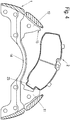
- FIG. 8 is the basic arrangement of an embodiment of a brake pad holder according to the invention for a disc brake, in particular for a commercial vehicle shown.
- a brake pad 2 is used with a lining carrier plate 21 and a friction lining 22 in a lining shaft 13 of a brake carrier 1.
- the brake carrier 1 spans a (not shown) brake disc, which rotates during travel of the motor vehicle in a main direction of rotation X when driving forward with a wheel axle of the motor vehicle and preferably on both sides of the brake disc arranged brake pads 2 are pressed in a braking operation of the brake disc.
- the lining shaft 13 is formed by the brake pads 2 laterally enclosing inlet side and outlet side Bremsnova critiquener 11, 12 and the brake carrier horns 11, 12 interconnecting bridge, wherein the distance between the two brake carrier horns 11, 12, viewed in the main direction of rotation X of the brake disc , is dimensioned so that a respective brake pad 2, in particular the pad carrier plate 21 of the brake pad 2, during assembly first with a first side end face to form a positive connection, for example by forming a projection 23 on the inlet side Bremsnovahorn 11 facing side of the pad carrier plate in a recess on the lining shaft 13 facing inside of the viewed in the direction of rotation X of the brake disc front first Bremseselhorn 11 and then completely inserted by a pivoting movement in the lining shaft 13, so that the opposite Side end face of the lining carrier plate 21 of the brake lining 2 is opposite to the second brake carrier horn 12 or bears against it.
- the brake pad 2 is held by a known pad retaining spring 3 in the lining shaft 13, wherein the preferably designed as a leaf spring pad retaining spring 3 is fixed in the embodiment shown here on a side facing away from the axis of rotation of the brake disc top of the lining support 21 of the brake pad 2 and upwards ie away from the axis of rotation of the brake disc on a brake carrier 1 in the direction of the vehicle axle spanning pad retaining bracket 4 is supported.
- the longitudinal extent of the pad retaining spring 3 is designed so that the pad retaining spring 3 in the assembled state with its end side facing the end extends into a formed on the outlet side Bremsharihorn 12 undercut 15.
- This undercut 15 is in a first embodiment, as in the FIGS. 1 to 4 and 8th is shown, shaped so that extending in the direction of the outlet side Bremsharihorns 12 rectilinear section or tail of the pad retaining spring 3 extends into the undercut 15 and thus keeps the brake pad 2 radially secured in its functional position in the brake carrier.
- a portion of the outlet side Bremsharihorns 12 is radially to the axis of rotation of the brake disc on the in the undercut 15 of the outlet side Bremseselhorns 12 extending portion 31 of the pad retaining spring.
- the portion 31 of the pad retaining spring 3 is hook-shaped.
- This hook-shaped portion 31 is formed so that in the relaxed state of the pad retaining spring 3, the free end of the hook-shaped portion 31 rests in the formed on the outlet side Bremsharihorn 12 undercut 15 and in this way the brake pad 2 radially secured in the brake carrier 1 holds.
- Particularly preferred is adapted for easy assembly and disassembly on the lining carrier plate 21 a contour of the hook-shaped portion 31 of the pad retaining spring 3 adapted recess 25 on the outlet side facing the carrier horn end face of the pad carrier plate 21, in which the portion 31 for mounting or dismounting the brake pad. 2 is intrusive.
- the shape of the undercut 15 at the outlet side carrier horn 12 can, as in FIGS. 1 to 4 shown, for example, be designed as a cross-sectionally triangular recess, wherein the portion 31 of the pad retaining spring 3 conforms to one of the surfaces of the undercut 15.
- undercut 15 in the form of a U-shaped slot, as shown in the FIGS. 5 to 8 is shown, which is particularly suitable for the hook-shaped configuration of the portion 31 of the pad retaining spring 3.
- the cross-sectional width of the undercut 15 preferably lies in a range between one and three material thicknesses of the portion 31 of the pad retaining spring 3.
Landscapes
- Engineering & Computer Science (AREA)
- General Engineering & Computer Science (AREA)
- Mechanical Engineering (AREA)
- Braking Arrangements (AREA)
Claims (8)
- Frein à disque d'un véhicule automobile, notamment d'un véhicule utilitaire, comprenant une fixation de garniture de frein, dans lequel des garnitures (2) de frein, associées des deux côtés à un disque de frein, ayant une garniture (22) de friction et une plaque (21) de porte-garniture portant la garniture (22) de friction sont, en étant soumises à l'action d'au moins un ressort (3) de maintien de garniture, montées avec possibilité d'être écartées radialement, respectivement dans un puits (13) de garniture d'un support (1) de frein fixe ayant des cornes (11, 12) de support de frein enchâssant latéralement les garnitures (2) de frein, la plaque (21) de porte-garniture des garnitures (2) de frein étant à l'état monté maintenue à complémentarité de forme sur une corne (11) du porte-frein du côté de l'entrée, caractérisé en ce qu'à l'état, inséré dans le puits (13) de garniture, de la garniture (2) de frein respective est constituée exclusivement d'un côté, tourné vers la corne (11) du support de frein du côté de l'entrée, de la plaque (21) de porte-garniture, une saillie (23), qui est insérée dans un évidement du côté intérieur, tourné vers le puits (13) de garniture, de la corne (11) du support de frein du côté de l'entrée et en ce qu'une sous-pièce (31) du ressort (3) de maintien de garniture s'étend, en la position montée, sur le bord, tourné vers la corne (12) de support de frein du côté de la sortie, de la plaque (21) de porte-garniture dans une contre-dépouille (15) formée sur la corne (12) du support de frein du côté de la sortie.
- Frein à disque suivant la revendication 1, caractérisé en ce que la sous-pièce (31) du ressort (3) de maintien de garniture est constituée sous la forme d'une sous-pièce s'étendant en ligne droite sur le bord, tourné vers la corne (12) de support de frein du côté de la sortie, de la plaque (21) de porte-garniture.
- Frein à disque suivant la revendication 1, caractérisé en ce que la sous-pièce (31) du ressort (3) de maintien de garniture a la forme d'un crochet.
- Frein à disque suivant la revendication 3, caractérisé en ce que, sur la plaque (21) de porte-garniture, est formé un évidement (25), qui est adapté au contour de la sous-pièce (31) en forme de crochet du ressort (3) de maintien de garniture et dans lequel la sous-pièce (31) du ressort (3) de maintien de la garniture peut être enfoncée pour le montage ou le démontage de la garniture (2) de frein.
- Frein à disque suivant l'une des revendications précédentes, caractérisé en ce que le ressort (3) de maintien de la garniture est constitué sous la forme d'un ressort à lame.
- Frein à disque suivant l'une des revendications précédentes, caractérisé en ce que la contre-dépouille (15) est constituée sous la forme d'une fente en forme de U en section transversale.
- Frein à disque suivant la revendication 6, caractérisé en ce que la largeur de la section transversale de la contre-dépouille (15) représente entre une et trois épaisseurs de matériau de la sous-pièce (31) du ressort (3) de maintien de la garniture.
- Frein à disque suivant l'une des revendications 1 à 5, caractérisé en ce que la contre-dépouille (15) a une section transversale triangulaire.
Applications Claiming Priority (3)
| Application Number | Priority Date | Filing Date | Title |
|---|---|---|---|
| DE102012111175 | 2012-11-20 | ||
| DE102013101781.9A DE102013101781A1 (de) | 2012-11-20 | 2013-02-22 | Bremsbelaghalterung für eine Scheibenbremse eines Kraftfahrzeugs |
| PCT/EP2013/074266 WO2014079870A1 (fr) | 2012-11-20 | 2013-11-20 | Dispositif de fixation de garniture de frein pour un frein à disque d'un véhicule automobile |
Publications (2)
| Publication Number | Publication Date |
|---|---|
| EP2923105A1 EP2923105A1 (fr) | 2015-09-30 |
| EP2923105B1 true EP2923105B1 (fr) | 2019-02-20 |
Family
ID=50625686
Family Applications (2)
| Application Number | Title | Priority Date | Filing Date |
|---|---|---|---|
| EP13792924.6A Revoked EP2923104B1 (fr) | 2012-11-20 | 2013-11-20 | Support de garniture de frein pour un frein à disque d'un véhicule à moteur |
| EP13792690.3A Revoked EP2923105B1 (fr) | 2012-11-20 | 2013-11-20 | Frein à disque d'un véhicule automobile |
Family Applications Before (1)
| Application Number | Title | Priority Date | Filing Date |
|---|---|---|---|
| EP13792924.6A Revoked EP2923104B1 (fr) | 2012-11-20 | 2013-11-20 | Support de garniture de frein pour un frein à disque d'un véhicule à moteur |
Country Status (3)
| Country | Link |
|---|---|
| EP (2) | EP2923104B1 (fr) |
| DE (2) | DE102013101781A1 (fr) |
| WO (2) | WO2014079870A1 (fr) |
Families Citing this family (14)
| Publication number | Priority date | Publication date | Assignee | Title |
|---|---|---|---|---|
| DE102013013686A1 (de) | 2013-08-16 | 2015-02-19 | Knorr-Bremse Systeme für Nutzfahrzeuge GmbH | Belaghaltefeder eines Bremsbelags und Bremsbelaghalterung für eine Scheibenbremse eines Kraftfahrzeugs |
| DE102014019618A1 (de) * | 2014-12-29 | 2016-06-30 | Wabco Europe Bvba | Scheibenbremse |
| DE102016104967A1 (de) * | 2015-10-09 | 2017-04-13 | Knorr-Bremse Systeme für Nutzfahrzeuge GmbH | Bremsträger |
| DE102015122585A1 (de) | 2015-12-22 | 2017-06-22 | Bpw Bergische Achsen Kg | Bremsbelaghalterung einer Fahrzeug-Scheibenbremse, Bremsbelag, Bügel einer Bremsbelaghalterung |
| WO2017151477A1 (fr) * | 2016-03-03 | 2017-09-08 | Bendix Spicer Foundation Brake Llc | Frein à disque et ensemble plaquette de frein |
| DK3458738T3 (da) | 2016-05-20 | 2023-02-27 | Knorr Bremse Systeme Fuer Nutzfahrzeuge Gmbh | Skivebremse til et erhvervskøretøj, bremsebelægning og bremsebelægningssæt |
| DK3458737T3 (da) | 2016-05-20 | 2022-08-01 | Knorr Bremse Systeme Fuer Nutzfahrzeuge Gmbh | Skivebremse til et erhvervskøretøj og bremsebelægningssæt |
| US10113599B2 (en) | 2017-02-07 | 2018-10-30 | Edwin Beachy | Retaining bracket for disc brake caliper and kit including the same |
| GB2563079A (en) * | 2017-06-02 | 2018-12-05 | Meritor Heavy Vehicle Braking Systems Uk Ltd | A disc brake |
| GB2563081A (en) | 2017-06-02 | 2018-12-05 | Meritor Heavy Vehicle Braking Systems Uk Ltd | A brake pad |
| GB2566335A (en) * | 2017-09-12 | 2019-03-13 | Meritor Heavy Vehicle Braking Systems Uk Ltd | A disc brake |
| DE102020106296A1 (de) * | 2020-03-09 | 2021-09-23 | Tmd Friction Services Gmbh | Belagträgerplatte für eine Scheibenbremse eines Kraftfahrzeugs sowie Verfahren zur deren Herstellung |
| CN112065892A (zh) * | 2020-08-26 | 2020-12-11 | 江苏凯迅达高铁传动技术开发有限公司 | 一种气压盘式制动器用钳体 |
| CN112081843B (zh) * | 2020-08-26 | 2025-01-03 | 江苏凯迅达高铁传动技术开发有限公司 | 一种气压盘式制动器 |
Citations (1)
| Publication number | Priority date | Publication date | Assignee | Title |
|---|---|---|---|---|
| WO2013143993A1 (fr) | 2012-03-26 | 2013-10-03 | Knorr-Bremse Systeme für Nutzfahrzeuge GmbH | Ensemble garniture de frein pour un frein à disque à étrier coulissant |
Family Cites Families (25)
| Publication number | Priority date | Publication date | Assignee | Title |
|---|---|---|---|---|
| FR82909E (fr) * | 1962-06-29 | 1964-05-08 | Dba Sa | Frein à disque |
| DE2038649A1 (de) * | 1969-08-07 | 1971-02-18 | Messier Sa | Scheibenbremse |
| US3841445A (en) | 1972-08-11 | 1974-10-15 | Kelsey Hayes Co | Hold-down assembly for sliding caliper type disk brake |
| JPS5141179A (fr) * | 1974-10-01 | 1976-04-06 | Aisin Seiki | |
| GB1519482A (en) | 1975-03-21 | 1978-07-26 | Girling Ltd | Disc brakes |
| US4068744A (en) * | 1976-08-30 | 1978-01-17 | The Bendix Corporation | Floatation and anchoring mechanism for disc brake |
| JPS6048654B2 (ja) | 1977-08-24 | 1985-10-29 | トヨタ自動車株式会社 | デイスクブレ−キ |
| DE2926818A1 (de) * | 1979-07-03 | 1981-03-12 | Alfred Teves Gmbh, 6000 Frankfurt | Teilbelagscheibenbremse. |
| US4618034A (en) * | 1985-03-18 | 1986-10-21 | Rockwell International Corporation | Brake shoe retention apparatus |
| DE3839957A1 (de) * | 1988-11-26 | 1990-05-31 | Teves Gmbh Alfred | Teilbelag-scheibenbremse |
| JPH1130256A (ja) * | 1997-07-14 | 1999-02-02 | Nissin Kogyo Kk | 車両用ディスクブレーキの摩擦パッド支持構造 |
| GB0214705D0 (en) | 2002-06-26 | 2002-08-07 | Meritor Heavy Vehicle Braking | Pad spring and disc brake incorporating a pad spring |
| DE102005052436B3 (de) | 2005-11-03 | 2007-08-16 | Knorr-Bremse Systeme für Nutzfahrzeuge GmbH | Scheibenbremse und Bremsbelag für eine Scheibenbremse, insbesondere für ein Nutzfahrzeug |
| US7784591B2 (en) * | 2006-03-15 | 2010-08-31 | Kelsey-Hayes Company | Defined brake pad abutment |
| DE102007048475A1 (de) * | 2006-10-10 | 2008-04-17 | Continental Teves Ag & Co. Ohg | Scheibenbremse mit Bremsbelag dafür |
| JP4803019B2 (ja) | 2006-12-20 | 2011-10-26 | トヨタ自動車株式会社 | ディスクブレーキ装置 |
| DE102007049980A1 (de) * | 2007-10-18 | 2009-04-23 | Knorr-Bremse Systeme für Nutzfahrzeuge GmbH | Scheibenbremse für ein Nutzfahrzeug sowie Bremsbelag für eine Scheibenbremse |
| DE102008029582A1 (de) * | 2007-10-19 | 2009-04-23 | Continental Teves Ag & Co. Ohg | Scheibenbremse |
| DE102009009567A1 (de) * | 2008-02-20 | 2009-09-03 | Continental Teves Ag & Co. Ohg | Schwimmsattel-Scheibenbremse sowie Bremsbelag hierfür |
| DE102008019265B4 (de) * | 2008-04-17 | 2025-02-13 | Knorr-Bremse Systeme für Nutzfahrzeuge GmbH | Bremsbelaghalterung einer Scheibenbremse |
| JP5178596B2 (ja) * | 2009-03-23 | 2013-04-10 | 曙ブレーキ工業株式会社 | ディスクブレーキ |
| DE102010019470B4 (de) | 2010-05-05 | 2016-05-19 | Knorr-Bremse Systeme für Nutzfahrzeuge GmbH | Scheibenbremse für ein Nutzfahrzeug sowie Bremsbelag für eine Scheibenbremse |
| JP5454352B2 (ja) * | 2010-05-20 | 2014-03-26 | 株式会社アドヴィックス | ディスクブレーキ装置 |
| DE102010023143A1 (de) * | 2010-06-09 | 2011-12-15 | Knorr-Bremse Systeme für Nutzfahrzeuge GmbH | Scheibenbremse für ein Nutzfahrzeug sowie Bremsbelag für eine Scheibenbremse |
| FR2969238B1 (fr) | 2010-12-17 | 2014-04-25 | Bosch Gmbh Robert | Organe de guidage unique d'un patin de frein a disque et frein a disque equipe de tels organes de guidage |
-
2013
- 2013-02-22 DE DE102013101781.9A patent/DE102013101781A1/de not_active Withdrawn
- 2013-02-22 DE DE102013101779.7A patent/DE102013101779A1/de not_active Ceased
- 2013-11-20 WO PCT/EP2013/074266 patent/WO2014079870A1/fr not_active Ceased
- 2013-11-20 EP EP13792924.6A patent/EP2923104B1/fr not_active Revoked
- 2013-11-20 EP EP13792690.3A patent/EP2923105B1/fr not_active Revoked
- 2013-11-20 WO PCT/EP2013/074265 patent/WO2014079869A1/fr not_active Ceased
Patent Citations (1)
| Publication number | Priority date | Publication date | Assignee | Title |
|---|---|---|---|---|
| WO2013143993A1 (fr) | 2012-03-26 | 2013-10-03 | Knorr-Bremse Systeme für Nutzfahrzeuge GmbH | Ensemble garniture de frein pour un frein à disque à étrier coulissant |
Also Published As
| Publication number | Publication date |
|---|---|
| DE102013101781A1 (de) | 2014-05-22 |
| WO2014079870A1 (fr) | 2014-05-30 |
| WO2014079869A1 (fr) | 2014-05-30 |
| DE102013101779A1 (de) | 2014-06-05 |
| EP2923104B1 (fr) | 2018-05-30 |
| EP2923104A1 (fr) | 2015-09-30 |
| EP2923105A1 (fr) | 2015-09-30 |
Similar Documents
| Publication | Publication Date | Title |
|---|---|---|
| EP2923105B1 (fr) | Frein à disque d'un véhicule automobile | |
| EP3359843B1 (fr) | Frein à disque pour véhicule utilitaire | |
| EP3516255B1 (fr) | Frein à disque pour véhicule utilitaire et jeu de garnitures de frein | |
| EP3308052B1 (fr) | Frein à disque pour véhicule utilitaire et jeu de garnitures de frein | |
| EP2812595B1 (fr) | Système de retenue de garniture d'un frein à disque d'un véhicule à moteur | |
| EP3033538B1 (fr) | Ressort de retenue d'une garniture de frein et élément de retenue de garniture de frein pour frein à disque d'un véhicule automobile | |
| EP2831457B1 (fr) | Ensemble garniture de frein pour un frein à disque à étrier coulissant | |
| EP3183466B1 (fr) | Frein à disque, étrier de frein et levier de frein rotatif | |
| EP3203102B2 (fr) | Garniture de frein et dispositif de retenue de garniture d'un frein à disque | |
| DE102017129672B4 (de) | Scheibenbremse für ein Nutzfahrzeug und Bremsbelagsatz | |
| DE2840374A1 (de) | Schwimmsattel-teilbelagscheibenbremse, insbesondere fuer kraftfahrzeuge | |
| DE102016120481A1 (de) | Scheibenbremse für ein Nutzfahrzeug und Bremsbelagsatz | |
| DE112014002773T5 (de) | Klammer zur Verwendung in einer Scheibenbremsvorrichtung und Scheibenbremsvorrichtung mit einer solchen Klammer | |
| DE102014112665A1 (de) | Bremsbelaghalterung einer Scheibenbremse, Scheibenbremse und Bremsbelag | |
| WO2015004080A1 (fr) | Fixation de garniture de frein à disque | |
| DE102012108689A1 (de) | Scheibenbremse für ein Fahrzeug | |
| DE102009030414B4 (de) | Bremsbelag für eine Scheibenbremse | |
| DE102014113617A1 (de) | Bremsbelaghalterung einer Scheibenbremse, Scheibenbremse und Bremsbelag | |
| EP2831446B1 (fr) | Frein à disque de véhicule à moteur et garniture de frein associée | |
| DE102014106090A1 (de) | Bremsbelaghalterung einer Scheibenbremse und Bremsbelag | |
| EP2831455B1 (fr) | Frein à disque et garniture de frein | |
| EP2679853B1 (fr) | Frein à disques pour un véhicule utilitaire et garniture de frein pour un frein à disques | |
| EP4045808A1 (fr) | Frein à disque pour un véhicule automobile et agencement d'au moins un ressort de retenue de patin et d'un couvercle sur un patin de frein | |
| DE102013013290A1 (de) | Bremsbelaganordnung mit Verschleißanzeiger sowie Verschleißanzeiger hierfür | |
| DE102022123484A1 (de) | Scheibenbremse für ein Nutzfahrzeug |
Legal Events
| Date | Code | Title | Description |
|---|---|---|---|
| PUAI | Public reference made under article 153(3) epc to a published international application that has entered the european phase |
Free format text: ORIGINAL CODE: 0009012 |
|
| 17P | Request for examination filed |
Effective date: 20150622 |
|
| AK | Designated contracting states |
Kind code of ref document: A1 Designated state(s): AL AT BE BG CH CY CZ DE DK EE ES FI FR GB GR HR HU IE IS IT LI LT LU LV MC MK MT NL NO PL PT RO RS SE SI SK SM TR |
|
| AX | Request for extension of the european patent |
Extension state: BA ME |
|
| RIN1 | Information on inventor provided before grant (corrected) |
Inventor name: HABERMANN, DIMITRIJ Inventor name: IRASCHKO, JOHANN |
|
| DAX | Request for extension of the european patent (deleted) | ||
| STAA | Information on the status of an ep patent application or granted ep patent |
Free format text: STATUS: EXAMINATION IS IN PROGRESS |
|
| 17Q | First examination report despatched |
Effective date: 20171212 |
|
| GRAP | Despatch of communication of intention to grant a patent |
Free format text: ORIGINAL CODE: EPIDOSNIGR1 |
|
| STAA | Information on the status of an ep patent application or granted ep patent |
Free format text: STATUS: GRANT OF PATENT IS INTENDED |
|
| INTG | Intention to grant announced |
Effective date: 20180910 |
|
| GRAS | Grant fee paid |
Free format text: ORIGINAL CODE: EPIDOSNIGR3 |
|
| GRAA | (expected) grant |
Free format text: ORIGINAL CODE: 0009210 |
|
| STAA | Information on the status of an ep patent application or granted ep patent |
Free format text: STATUS: THE PATENT HAS BEEN GRANTED |
|
| AK | Designated contracting states |
Kind code of ref document: B1 Designated state(s): AL AT BE BG CH CY CZ DE DK EE ES FI FR GB GR HR HU IE IS IT LI LT LU LV MC MK MT NL NO PL PT RO RS SE SI SK SM TR |
|
| REG | Reference to a national code |
Ref country code: GB Ref legal event code: FG4D Free format text: NOT ENGLISH |
|
| REG | Reference to a national code |
Ref country code: CH Ref legal event code: EP |
|
| REG | Reference to a national code |
Ref country code: DE Ref legal event code: R096 Ref document number: 502013012239 Country of ref document: DE |
|
| REG | Reference to a national code |
Ref country code: AT Ref legal event code: REF Ref document number: 1098587 Country of ref document: AT Kind code of ref document: T Effective date: 20190315 |
|
| REG | Reference to a national code |
Ref country code: IE Ref legal event code: FG4D Free format text: LANGUAGE OF EP DOCUMENT: GERMAN |
|
| REG | Reference to a national code |
Ref country code: NL Ref legal event code: FP |
|
| REG | Reference to a national code |
Ref country code: SE Ref legal event code: TRGR |
|
| REG | Reference to a national code |
Ref country code: LT Ref legal event code: MG4D |
|
| PG25 | Lapsed in a contracting state [announced via postgrant information from national office to epo] |
Ref country code: LT Free format text: LAPSE BECAUSE OF FAILURE TO SUBMIT A TRANSLATION OF THE DESCRIPTION OR TO PAY THE FEE WITHIN THE PRESCRIBED TIME-LIMIT Effective date: 20190220 Ref country code: FI Free format text: LAPSE BECAUSE OF FAILURE TO SUBMIT A TRANSLATION OF THE DESCRIPTION OR TO PAY THE FEE WITHIN THE PRESCRIBED TIME-LIMIT Effective date: 20190220 Ref country code: PT Free format text: LAPSE BECAUSE OF FAILURE TO SUBMIT A TRANSLATION OF THE DESCRIPTION OR TO PAY THE FEE WITHIN THE PRESCRIBED TIME-LIMIT Effective date: 20190620 Ref country code: NO Free format text: LAPSE BECAUSE OF FAILURE TO SUBMIT A TRANSLATION OF THE DESCRIPTION OR TO PAY THE FEE WITHIN THE PRESCRIBED TIME-LIMIT Effective date: 20190520 |
|
| PG25 | Lapsed in a contracting state [announced via postgrant information from national office to epo] |
Ref country code: BG Free format text: LAPSE BECAUSE OF FAILURE TO SUBMIT A TRANSLATION OF THE DESCRIPTION OR TO PAY THE FEE WITHIN THE PRESCRIBED TIME-LIMIT Effective date: 20190520 Ref country code: LV Free format text: LAPSE BECAUSE OF FAILURE TO SUBMIT A TRANSLATION OF THE DESCRIPTION OR TO PAY THE FEE WITHIN THE PRESCRIBED TIME-LIMIT Effective date: 20190220 Ref country code: IS Free format text: LAPSE BECAUSE OF FAILURE TO SUBMIT A TRANSLATION OF THE DESCRIPTION OR TO PAY THE FEE WITHIN THE PRESCRIBED TIME-LIMIT Effective date: 20190620 Ref country code: RS Free format text: LAPSE BECAUSE OF FAILURE TO SUBMIT A TRANSLATION OF THE DESCRIPTION OR TO PAY THE FEE WITHIN THE PRESCRIBED TIME-LIMIT Effective date: 20190220 Ref country code: HR Free format text: LAPSE BECAUSE OF FAILURE TO SUBMIT A TRANSLATION OF THE DESCRIPTION OR TO PAY THE FEE WITHIN THE PRESCRIBED TIME-LIMIT Effective date: 20190220 |
|
| PG25 | Lapsed in a contracting state [announced via postgrant information from national office to epo] |
Ref country code: CZ Free format text: LAPSE BECAUSE OF FAILURE TO SUBMIT A TRANSLATION OF THE DESCRIPTION OR TO PAY THE FEE WITHIN THE PRESCRIBED TIME-LIMIT Effective date: 20190220 Ref country code: AL Free format text: LAPSE BECAUSE OF FAILURE TO SUBMIT A TRANSLATION OF THE DESCRIPTION OR TO PAY THE FEE WITHIN THE PRESCRIBED TIME-LIMIT Effective date: 20190220 Ref country code: RO Free format text: LAPSE BECAUSE OF FAILURE TO SUBMIT A TRANSLATION OF THE DESCRIPTION OR TO PAY THE FEE WITHIN THE PRESCRIBED TIME-LIMIT Effective date: 20190220 Ref country code: ES Free format text: LAPSE BECAUSE OF FAILURE TO SUBMIT A TRANSLATION OF THE DESCRIPTION OR TO PAY THE FEE WITHIN THE PRESCRIBED TIME-LIMIT Effective date: 20190220 Ref country code: EE Free format text: LAPSE BECAUSE OF FAILURE TO SUBMIT A TRANSLATION OF THE DESCRIPTION OR TO PAY THE FEE WITHIN THE PRESCRIBED TIME-LIMIT Effective date: 20190220 Ref country code: SK Free format text: LAPSE BECAUSE OF FAILURE TO SUBMIT A TRANSLATION OF THE DESCRIPTION OR TO PAY THE FEE WITHIN THE PRESCRIBED TIME-LIMIT Effective date: 20190220 Ref country code: DK Free format text: LAPSE BECAUSE OF FAILURE TO SUBMIT A TRANSLATION OF THE DESCRIPTION OR TO PAY THE FEE WITHIN THE PRESCRIBED TIME-LIMIT Effective date: 20190220 |
|
| REG | Reference to a national code |
Ref country code: DE Ref legal event code: R026 Ref document number: 502013012239 Country of ref document: DE |
|
| PLBI | Opposition filed |
Free format text: ORIGINAL CODE: 0009260 |
|
| PG25 | Lapsed in a contracting state [announced via postgrant information from national office to epo] |
Ref country code: PL Free format text: LAPSE BECAUSE OF FAILURE TO SUBMIT A TRANSLATION OF THE DESCRIPTION OR TO PAY THE FEE WITHIN THE PRESCRIBED TIME-LIMIT Effective date: 20190220 Ref country code: SM Free format text: LAPSE BECAUSE OF FAILURE TO SUBMIT A TRANSLATION OF THE DESCRIPTION OR TO PAY THE FEE WITHIN THE PRESCRIBED TIME-LIMIT Effective date: 20190220 |
|
| PLAX | Notice of opposition and request to file observation + time limit sent |
Free format text: ORIGINAL CODE: EPIDOSNOBS2 |
|
| 26 | Opposition filed |
Opponent name: VRI-VERBAND DER REIBBELAGINDUSTRIE E.V. Effective date: 20191107 |
|
| PGFP | Annual fee paid to national office [announced via postgrant information from national office to epo] |
Ref country code: SE Payment date: 20191125 Year of fee payment: 7 Ref country code: DE Payment date: 20191125 Year of fee payment: 7 |
|
| PG25 | Lapsed in a contracting state [announced via postgrant information from national office to epo] |
Ref country code: SI Free format text: LAPSE BECAUSE OF FAILURE TO SUBMIT A TRANSLATION OF THE DESCRIPTION OR TO PAY THE FEE WITHIN THE PRESCRIBED TIME-LIMIT Effective date: 20190220 |
|
| PGFP | Annual fee paid to national office [announced via postgrant information from national office to epo] |
Ref country code: FR Payment date: 20191121 Year of fee payment: 7 Ref country code: IT Payment date: 20191120 Year of fee payment: 7 |
|
| PGFP | Annual fee paid to national office [announced via postgrant information from national office to epo] |
Ref country code: GB Payment date: 20191126 Year of fee payment: 7 |
|
| REG | Reference to a national code |
Ref country code: CH Ref legal event code: PL |
|
| PLAF | Information modified related to communication of a notice of opposition and request to file observations + time limit |
Free format text: ORIGINAL CODE: EPIDOSCOBS2 |
|
| REG | Reference to a national code |
Ref country code: NL Ref legal event code: MM Effective date: 20191201 |
|
| PG25 | Lapsed in a contracting state [announced via postgrant information from national office to epo] |
Ref country code: LI Free format text: LAPSE BECAUSE OF NON-PAYMENT OF DUE FEES Effective date: 20191130 Ref country code: CH Free format text: LAPSE BECAUSE OF NON-PAYMENT OF DUE FEES Effective date: 20191130 Ref country code: MC Free format text: LAPSE BECAUSE OF FAILURE TO SUBMIT A TRANSLATION OF THE DESCRIPTION OR TO PAY THE FEE WITHIN THE PRESCRIBED TIME-LIMIT Effective date: 20190220 Ref country code: LU Free format text: LAPSE BECAUSE OF NON-PAYMENT OF DUE FEES Effective date: 20191120 |
|
| REG | Reference to a national code |
Ref country code: BE Ref legal event code: MM Effective date: 20191130 |
|
| PG25 | Lapsed in a contracting state [announced via postgrant information from national office to epo] |
Ref country code: NL Free format text: LAPSE BECAUSE OF NON-PAYMENT OF DUE FEES Effective date: 20191201 |
|
| PG25 | Lapsed in a contracting state [announced via postgrant information from national office to epo] |
Ref country code: IE Free format text: LAPSE BECAUSE OF NON-PAYMENT OF DUE FEES Effective date: 20191120 |
|
| PLBB | Reply of patent proprietor to notice(s) of opposition received |
Free format text: ORIGINAL CODE: EPIDOSNOBS3 |
|
| PG25 | Lapsed in a contracting state [announced via postgrant information from national office to epo] |
Ref country code: BE Free format text: LAPSE BECAUSE OF NON-PAYMENT OF DUE FEES Effective date: 20191130 |
|
| REG | Reference to a national code |
Ref country code: AT Ref legal event code: MM01 Ref document number: 1098587 Country of ref document: AT Kind code of ref document: T Effective date: 20191120 |
|
| PLAY | Examination report in opposition despatched + time limit |
Free format text: ORIGINAL CODE: EPIDOSNORE2 |
|
| PG25 | Lapsed in a contracting state [announced via postgrant information from national office to epo] |
Ref country code: AT Free format text: LAPSE BECAUSE OF NON-PAYMENT OF DUE FEES Effective date: 20191120 |
|
| PG25 | Lapsed in a contracting state [announced via postgrant information from national office to epo] |
Ref country code: CY Free format text: LAPSE BECAUSE OF FAILURE TO SUBMIT A TRANSLATION OF THE DESCRIPTION OR TO PAY THE FEE WITHIN THE PRESCRIBED TIME-LIMIT Effective date: 20190220 |
|
| REG | Reference to a national code |
Ref country code: DE Ref legal event code: R119 Ref document number: 502013012239 Country of ref document: DE |
|
| REG | Reference to a national code |
Ref country code: SE Ref legal event code: EUG |
|
| PG25 | Lapsed in a contracting state [announced via postgrant information from national office to epo] |
Ref country code: GR Free format text: LAPSE BECAUSE OF FAILURE TO SUBMIT A TRANSLATION OF THE DESCRIPTION OR TO PAY THE FEE WITHIN THE PRESCRIBED TIME-LIMIT Effective date: 20190220 |
|
| GBPC | Gb: european patent ceased through non-payment of renewal fee |
Effective date: 20201120 |
|
| PG25 | Lapsed in a contracting state [announced via postgrant information from national office to epo] |
Ref country code: HU Free format text: LAPSE BECAUSE OF FAILURE TO SUBMIT A TRANSLATION OF THE DESCRIPTION OR TO PAY THE FEE WITHIN THE PRESCRIBED TIME-LIMIT; INVALID AB INITIO Effective date: 20131120 Ref country code: MT Free format text: LAPSE BECAUSE OF FAILURE TO SUBMIT A TRANSLATION OF THE DESCRIPTION OR TO PAY THE FEE WITHIN THE PRESCRIBED TIME-LIMIT Effective date: 20190220 |
|
| PG25 | Lapsed in a contracting state [announced via postgrant information from national office to epo] |
Ref country code: SE Free format text: LAPSE BECAUSE OF NON-PAYMENT OF DUE FEES Effective date: 20201121 |
|
| PLAH | Information related to despatch of examination report in opposition + time limit modified |
Free format text: ORIGINAL CODE: EPIDOSCORE2 |
|
| PG25 | Lapsed in a contracting state [announced via postgrant information from national office to epo] |
Ref country code: IT Free format text: LAPSE BECAUSE OF NON-PAYMENT OF DUE FEES Effective date: 20201120 Ref country code: FR Free format text: LAPSE BECAUSE OF NON-PAYMENT OF DUE FEES Effective date: 20201130 |
|
| PG25 | Lapsed in a contracting state [announced via postgrant information from national office to epo] |
Ref country code: DE Free format text: LAPSE BECAUSE OF NON-PAYMENT OF DUE FEES Effective date: 20210601 Ref country code: GB Free format text: LAPSE BECAUSE OF NON-PAYMENT OF DUE FEES Effective date: 20201120 |
|
| PLBC | Reply to examination report in opposition received |
Free format text: ORIGINAL CODE: EPIDOSNORE3 |
|
| PG25 | Lapsed in a contracting state [announced via postgrant information from national office to epo] |
Ref country code: MK Free format text: LAPSE BECAUSE OF FAILURE TO SUBMIT A TRANSLATION OF THE DESCRIPTION OR TO PAY THE FEE WITHIN THE PRESCRIBED TIME-LIMIT Effective date: 20190220 |
|
| RDAF | Communication despatched that patent is revoked |
Free format text: ORIGINAL CODE: EPIDOSNREV1 |
|
| REG | Reference to a national code |
Ref country code: DE Ref legal event code: R103 Ref document number: 502013012239 Country of ref document: DE Ref country code: DE Ref legal event code: R064 Ref document number: 502013012239 Country of ref document: DE |
|
| RDAG | Patent revoked |
Free format text: ORIGINAL CODE: 0009271 |
|
| STAA | Information on the status of an ep patent application or granted ep patent |
Free format text: STATUS: PATENT REVOKED |
|
| REG | Reference to a national code |
Ref country code: CH Ref legal event code: PL |
|
| 27W | Patent revoked |
Effective date: 20240306 |
|
| PG25 | Lapsed in a contracting state [announced via postgrant information from national office to epo] |
Ref country code: TR Free format text: LAPSE BECAUSE OF NON-PAYMENT OF DUE FEES Effective date: 20191120 |
|
| REG | Reference to a national code |
Ref country code: AT Ref legal event code: MA03 Ref document number: 1098587 Country of ref document: AT Kind code of ref document: T Effective date: 20240306 |