EP2923724A2 - Katheter - Google Patents
Katheter Download PDFInfo
- Publication number
- EP2923724A2 EP2923724A2 EP15159943.8A EP15159943A EP2923724A2 EP 2923724 A2 EP2923724 A2 EP 2923724A2 EP 15159943 A EP15159943 A EP 15159943A EP 2923724 A2 EP2923724 A2 EP 2923724A2
- Authority
- EP
- European Patent Office
- Prior art keywords
- distal end
- catheter
- coil body
- end tip
- tip
- Prior art date
- Legal status (The legal status is an assumption and is not a legal conclusion. Google has not performed a legal analysis and makes no representation as to the accuracy of the status listed.)
- Granted
Links
Images


Classifications
-
- A—HUMAN NECESSITIES
- A61—MEDICAL OR VETERINARY SCIENCE; HYGIENE
- A61M—DEVICES FOR INTRODUCING MEDIA INTO, OR ONTO, THE BODY; DEVICES FOR TRANSDUCING BODY MEDIA OR FOR TAKING MEDIA FROM THE BODY; DEVICES FOR PRODUCING OR ENDING SLEEP OR STUPOR
- A61M25/00—Catheters; Hollow probes
- A61M25/0067—Catheters; Hollow probes characterised by the distal end, e.g. tips
- A61M25/008—Strength or flexibility characteristics of the catheter tip
-
- A—HUMAN NECESSITIES
- A61—MEDICAL OR VETERINARY SCIENCE; HYGIENE
- A61M—DEVICES FOR INTRODUCING MEDIA INTO, OR ONTO, THE BODY; DEVICES FOR TRANSDUCING BODY MEDIA OR FOR TAKING MEDIA FROM THE BODY; DEVICES FOR PRODUCING OR ENDING SLEEP OR STUPOR
- A61M25/00—Catheters; Hollow probes
- A61M25/0043—Catheters; Hollow probes characterised by structural features
- A61M25/005—Catheters; Hollow probes characterised by structural features with embedded materials for reinforcement, e.g. wires, coils, braids
-
- A—HUMAN NECESSITIES
- A61—MEDICAL OR VETERINARY SCIENCE; HYGIENE
- A61M—DEVICES FOR INTRODUCING MEDIA INTO, OR ONTO, THE BODY; DEVICES FOR TRANSDUCING BODY MEDIA OR FOR TAKING MEDIA FROM THE BODY; DEVICES FOR PRODUCING OR ENDING SLEEP OR STUPOR
- A61M25/00—Catheters; Hollow probes
- A61M25/0043—Catheters; Hollow probes characterised by structural features
- A61M25/005—Catheters; Hollow probes characterised by structural features with embedded materials for reinforcement, e.g. wires, coils, braids
- A61M25/0053—Catheters; Hollow probes characterised by structural features with embedded materials for reinforcement, e.g. wires, coils, braids having a variable stiffness along the longitudinal axis, e.g. by varying the pitch of the coil or braid
-
- A—HUMAN NECESSITIES
- A61—MEDICAL OR VETERINARY SCIENCE; HYGIENE
- A61M—DEVICES FOR INTRODUCING MEDIA INTO, OR ONTO, THE BODY; DEVICES FOR TRANSDUCING BODY MEDIA OR FOR TAKING MEDIA FROM THE BODY; DEVICES FOR PRODUCING OR ENDING SLEEP OR STUPOR
- A61M25/00—Catheters; Hollow probes
- A61M25/0067—Catheters; Hollow probes characterised by the distal end, e.g. tips
- A61M25/0068—Static characteristics of the catheter tip, e.g. shape, atraumatic tip, curved tip or tip structure
- A61M25/0069—Tip not integral with tube
Definitions
- the present invention relates to a catheter that can be inserted into a hard stenosis or a bone.
- Therapeutic catheters that are inserted into hard stenoses for example, calcified stenoses formed in blood vessels, bile ducts, pancreatic ducts, etc., and bone-marrow-sucking catheters that are inserted into bones to suck bone marrow are generally provided with distal end tips made of a rigid metal.
- the distal end tips are attached to the distal ends of catheter shafts so that the catheters can be inserted into the hard stenoses and bones (see, for example, Japanese Unexamined Patent Application Publication No. 2007-244492 (hereinafter referred to as Patent Document 1)).
- an outer layer of the catheter is removed to expose a braid, and a distal end tip made of a metal is bonded to the braid, so that the distal end tip is bonded to a catheter shaft with sufficient bonding strength.
- the catheter according to Patent Document 1 since the distal end tip made of a metal is bonded to an outer peripheral surface of the braid, the outer diameter of the distal end tip is greater than the outer diameter of the catheter shaft. Therefore, the insertion performance of the catheter that is inserted into a hard stenosis or a bone is degraded.
- a hard stenosis is formed at an end of a blood vessel, a bile duct, a pancreatic duct, or the like
- the catheter inserted into the blood vessel, bile duct, pancreatic duct, or the like is greatly bent. Therefore, load is concentrated at a bonding portion between the proximal end of the distal end tip and the braid.
- the catheter When the catheter is rotated in this state, there is a risk that the proximal end of the distal end tip made of a metal will be partially separated from the braid.
- the catheter when the catheter is rotated while the catheter is greatly bent and the distal end tip is caught on the hard stenosis or bone, there is a risk that the proximal end of the distal end tip made of a metal will be separated from the braid due to the load concentrated at the bonding portion between the proximal end of the distal end tip and the braid.
- the proximal end of the distal end tip that has been separated from the braid may break through the outer layer and damage a normal portion of the blood vessel, bile duct, pancreatic duct, or the like.
- the distal end tip itself will break off from the catheter shaft and be left in the blood vessel, bile duct, pancreatic duct, or the like.
- a catheter includes tubular catheter shaft extending from a proximal end to a distal end and including a main body and a distal end portion, the main body including an inner layer having or defining a first space, a coil body wound around an outer periphery of the inner layer and made of a metal, and an outer layer that covers an outer periphery of the coil body; and a distal end tip having or defining a second space that communicates with the first space, the distal end tip being provided at a distal end of the catheter shaft and made of a metal.
- the distal end portion includes the coil body and the outer layer but does not include the inner layer.
- the distal end tip is bonded to a distal end of the coil body and an inner surface of of the coil body in the distal end portion.
- the distal end tip made of a metal is bonded to the distal end of the coil body and the inner surface of the coil body in the distal end portion. Therefore, sufficient bonding strength can be provided between the distal end tip and the coil body without making the outer diameter of the distal end tip greater than the outer diameter of the catheter shaft. As a result, the insertion performance of the catheter that is inserted into a hard stenosis or a bone can be improved. In addition, since the distal end tip made of a metal is bonded not only to the distal end of the coil body but also to the inner surface of the coil body, the risk that the distal end tip itself will break off from the catheter shaft can be reduced.
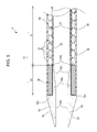
- Fig. 5 is an enlarged view of a catheter according to a second embodiment, which is a modification of the structure illustrated in Fig. 2 .
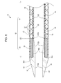
- Fig. 6 is an enlarged view of a catheter according to a third embodiment, which is a modification of the structure illustrated in Fig. 5 .
- a catheter 1 according to the present embodiment will be described with reference to Figs. 1 to 4 .
- a distal end of the catheter 1 that is inserted into a body is at the left side
- a proximal end of the catheter 1 that is manipulated by an operator, such as a doctor is at the right side.
- the catheter 1 is used, for example, to treat a stenosis in a blood vessel of the heart, a bile duct, or a pancreatic duct, or to suck bone marrow from a bone.
- the catheter 1 mainly includes a catheter shaft 10, a connector 14 attached to the proximal end of the catheter shaft 10, and a distal end tip 50 made of a metal and attached to the distal end of the catheter shaft 10.
- the catheter shaft 10 includes a main body 13 and a distal end portion 33.
- the main body 13 of the catheter shaft 10 includes an inner layer 20, a coil body 30 that serves as a reinforcing member, and an outer layer 40.
- the inner layer 20 is made of a resin, and forms an (inner) space 22 that allows a guidewire or another catheter to be inserted therethrough.
- the resin material of the inner layer 20 is not particularly limited. However, considering the slidability of the guidewire and another catheter inserted through the lumen 22, polytetrafluoroethylene (PTFE) is preferably used.
- the coil body 30 made of a metal is wound around the outer periphery of the inner layer 20.
- the coil body 30 is formed of or includes wires 31.
- Each wire 31 may either be a single wire or a stranded wire formed by twisting a plurality of wires together. Considering the rotating force of the catheter 1, the wires 31 included in the coil body 30 are preferably stranded wires.
- the metal material of the wires 31 is not particularly limited, and a stainless steel (SUS304, SUS316, etc.), gold, platinum, tungsten, nickel, or an alloy thereof may be used.
- the outer periphery of the coil body 30 is covered with the outer layer 40 made of a resin.
- the resin material of the outer layer 40 is not particularly limited, and polyamide, polyamide elastomer, polyester, polyurethane, etc., may be used.
- the distal end tip 50 made of a metal is attached to the distal end of the catheter shaft 10.
- the distal end tip 50 includes an outer peripheral surface 54 that is tapered such that the diameter thereof decreases toward the distal end, and an (inner) space 52 that communicates with the space 22 of the inner layer 20 and that allows a guidewire or another catheter to be inserted therethrough.
- the lumen 52 includes a straight portion 52a that has a substantially constant (inner) diameter and a tapered portion 52b that has an (inner) diameter that increases toward the proximal end as the thickness of the distal end tip 50 decreases toward the proximal end.
- the metal material of the distal end tip 50 is not particularly limited, and a stainless steel (SUS304, SUS316, etc.), gold, platinum, tungsten, nickel, or an alloy thereof may be used. At least one of the distal end tip 50 and the coil body 30 is preferably made of a radiopaque metal material so that the position of the distal end of the catheter 1 can be determined in a radiographic image.
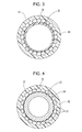
- Fig. 3 is a sectional view of Fig. 2 taken along line III-III.
- the main body 13 of the catheter shaft 10 includes the inner layer 20, the coil body 30, and the outer layer 40 arranged in that order in the radial direction.
- Fig. 4 is a sectional view of Fig. 2 taken along line IV-IV.
- the distal end portion 33 of the catheter shaft 10 includes the distal end tip 50, the coil body 30, and the outer layer 40 arranged in that order in the radial direction. Accordingly, the distal end portion 33 does not include the inner layer 20.
- the distal end tip 50 is bonded to a distal end 32 of the coil body 30 and an inner surface 34 of the coil body 30 (see Figs. 2 and 4 ).
- the length of the distal end portion 33 of the catheter shaft 10 can be adjusted as appropriate.
- the length of the distal end portion 33 of the catheter shaft 10 (in other words, the length of a portion of the coil body 30 that is bonded to the distal end tip 50) corresponds to four turns of the wires 31 of the coil body 30.
- the length of the distal end portion 33 may be increased to, for example, a length corresponding to six turns of the wires 31 of the coil body 30. In the case where the bonding strength between the distal end tip 50 and the coil body 30 is sufficient, the length of the distal end portion 33 may be reduced.
- the length of the distal end portion 33 of the catheter shaft 10 to which the distal end tip 50 is bonded can be adjusted to any length. Therefore, sufficient bonding strength can be provided between the distal end tip 50 and the coil body 30 and, thus, the catheter shaft 10 without making the outer diameter of the distal end tip 50 greater than the outer diameter of the catheter shaft 10. As a result, the insertion performance of the catheter 1 that is inserted into a hard stenosis or a bone can be improved.
- the distal end tip 50 made of a metal is bonded not only to the distal end 32 of the coil body 30 but also to the inner surface 34 of the coil body 30, the risk that the distal end tip 50 itself will break off from the catheter shaft 10 can be reduced.
- the distal end tip 50 which is bonded to the inner surface 34 of the coil body 30, includes the tapered portion 52b having a thickness that decreases toward the proximal end 50a so that the thickness is at a minimum at the proximal end 50a.
- the rigidity of the distal end tip 50 gradually increases from the proximal end 50a toward the distal end.
- a catheter 1a according to a second embodiment will be described with reference to Fig. 5 . Similar to Figs. 1 and 2 , in Fig. 5 , a distal end of the catheter 1a that is inserted into a body is at the left side, and a proximal end of the catheter 1a that is manipulated by an operator, such as a doctor, is at the right side.
- a distal end portion 33 of a catheter shaft 10 includes a bonding portion 36 in which the wires 31 forming or included in a coil body 30 are bonded together.
- the bonding portion 36 is formed by melting the wires 31 included in the coil body 30 with a laser or the like.
- a distal end tip 50 is bonded to a distal end 32a of the bonding portion 36 and an inner surface 34a of the bonding portion 36.
- the inner surface 34a of the bonding portion 36 is flatter or smoother than an inner surface 35 of the coil body 30 in a main body 13 of the catheter shaft 10 (in other words, the inner surface 35 of a portion of the coil body 30 that is not bonded to the distal end tip 50). Since the inner peripheral surface 34a of the bonding portion 36 is flat or smooth, the bonding area between the distal end tip 50 and the coil body 30 can be increased, and the risk that the distal end tip 50 will be separated from the coil body 30 can be reduced. As a result, the risk that the distal end tip 50 itself will break off from the catheter shaft 10 can be reduced.
- a catheter 1b according to a third embodiment will be described with reference to Fig. 6 . Similar to Figs. 1 , 2 , and 5 , in Fig. 6 , a distal end of the catheter 1b that is inserted into a body is at the left side, and a proximal end of the catheter 1b that is manipulated by an operator, such as a doctor, is at the right side.
- the catheter 1b includes a catheter shaft 10 including a main body 13 in which a braid 70 is embedded between an inner layer 20 and a coil body 30 so as to extend in the longitudinal direction.
- the braid 70 is not provided in the distal end portion 33.
- a proximal end 50a of the distal end tip 50 may be bonded not only to the coil body 30 but also to the braid 70. In such a case, the risk that the distal end tip 50 will be separated from the coil body 30 and the braid 70 can be reduced. As a result, the risk that the distal end tip 50 itself will break off from the catheter shaft 10 can be further reduced.
- the distal end tip 50 is attached to the distal end 32, 32a of the coil body 30 and the inner surface 34, 34a of the coil body 30. Therefore, sufficient bonding strength can be provided between the distal end tip 50 and the coil body 30 and, thus, the catheter shaft 10 without making the outer diameter of the distal end tip 50 greater than the outer diameter of the catheter shaft 10. As a result, the insertion performance of the catheter 1 that is inserted into a hard stenosis or a bone can be improved. In addition, the risk that the distal end tip 50 itself will break off from the catheter shaft 10 can be reduced.
Landscapes
- Health & Medical Sciences (AREA)
- Life Sciences & Earth Sciences (AREA)
- Biophysics (AREA)
- Pulmonology (AREA)
- Engineering & Computer Science (AREA)
- Anesthesiology (AREA)
- Biomedical Technology (AREA)
- Heart & Thoracic Surgery (AREA)
- Hematology (AREA)
- Animal Behavior & Ethology (AREA)
- General Health & Medical Sciences (AREA)
- Public Health (AREA)
- Veterinary Medicine (AREA)
- Media Introduction/Drainage Providing Device (AREA)
- Materials For Medical Uses (AREA)
Applications Claiming Priority (1)
| Application Number | Priority Date | Filing Date | Title |
|---|---|---|---|
| JP2014062106A JP5901078B2 (ja) | 2014-03-25 | 2014-03-25 | カテーテル |
Publications (3)
| Publication Number | Publication Date |
|---|---|
| EP2923724A2 true EP2923724A2 (de) | 2015-09-30 |
| EP2923724A3 EP2923724A3 (de) | 2015-10-21 |
| EP2923724B1 EP2923724B1 (de) | 2019-09-18 |
Family
ID=52706041
Family Applications (1)
| Application Number | Title | Priority Date | Filing Date |
|---|---|---|---|
| EP15159943.8A Active EP2923724B1 (de) | 2014-03-25 | 2015-03-19 | Katheter |
Country Status (4)
| Country | Link |
|---|---|
| US (1) | US9339629B2 (de) |
| EP (1) | EP2923724B1 (de) |
| JP (1) | JP5901078B2 (de) |
| CN (1) | CN104941048B (de) |
Cited By (2)
| Publication number | Priority date | Publication date | Assignee | Title |
|---|---|---|---|---|
| EP3260155A1 (de) * | 2016-06-24 | 2017-12-27 | Asahi Intecc Co., Ltd. | Katheter |
| EP3508242A4 (de) * | 2016-09-01 | 2020-05-13 | Asahi Intecc Co., Ltd. | Katheter |
Families Citing this family (23)
| Publication number | Priority date | Publication date | Assignee | Title |
|---|---|---|---|---|
| JP6344762B2 (ja) * | 2014-05-21 | 2018-06-20 | 朝日インテック株式会社 | カテーテル |
| US20170333060A1 (en) * | 2016-05-19 | 2017-11-23 | Justin P. Panian | Catheter assembly for blood clots removal |
| EP3484568B2 (de) | 2016-07-13 | 2025-07-16 | Perfuze Limited | Hochflexibler und knickbeständiger katheterschaft |
| EP3532146B8 (de) * | 2016-10-25 | 2024-08-14 | Muffin Incorporated | Vaskuläre verankerung einer einführschleuse |
| JPWO2018163401A1 (ja) * | 2017-03-10 | 2019-11-07 | 朝日インテック株式会社 | カテーテル |
| CN110799233A (zh) * | 2017-06-29 | 2020-02-14 | 朝日英达科株式会社 | 导管 |
| JP7006020B2 (ja) * | 2017-08-25 | 2022-01-24 | 住友ベークライト株式会社 | カテーテル、及び、カテーテルキット |
| CN114796808A (zh) * | 2017-09-30 | 2022-07-29 | 朝日英达科株式会社 | 导丝 |
| JP6868319B2 (ja) * | 2017-10-25 | 2021-05-12 | 朝日インテック株式会社 | カテーテル |
| ES2894768T3 (es) | 2017-12-15 | 2022-02-15 | Perfuze Ltd | Catéteres mejorados y dispositivos y sistemas que incorporan tales catéteres |
| CN111405921A (zh) * | 2018-01-25 | 2020-07-10 | 朝日英达科株式会社 | 导管 |
| WO2019146088A1 (ja) * | 2018-01-26 | 2019-08-01 | 朝日インテック株式会社 | カテーテル |
| JP6850368B2 (ja) * | 2018-01-26 | 2021-03-31 | 朝日インテック株式会社 | カテーテル |
| WO2019175996A1 (ja) * | 2018-03-14 | 2019-09-19 | 朝日インテック株式会社 | 体内回収機構用シャフト |
| WO2019189533A1 (ja) * | 2018-03-29 | 2019-10-03 | テルモ株式会社 | カテーテル組立体 |
| US10953195B2 (en) * | 2018-06-01 | 2021-03-23 | Covidien Lp | Flexible tip catheter |
| CN110639114B (zh) * | 2018-06-27 | 2023-03-17 | 先健科技(深圳)有限公司 | 导管 |
| JP7326597B2 (ja) * | 2019-10-30 | 2023-08-15 | ボストン サイエンティフィック サイムド,インコーポレイテッド | 内視鏡カテーテル装置 |
| US11452849B2 (en) * | 2021-01-22 | 2022-09-27 | MicroLinerTechnologies, Inc. | Systems and devices for atraumatic catheter insertion along a guidewire |
| WO2022176604A1 (ja) * | 2021-02-22 | 2022-08-25 | 株式会社カネカ | 穿刺デバイス |
| WO2023140935A1 (en) * | 2022-01-24 | 2023-07-27 | Becton, Dickinson And Company | Catheter assembly and related methods |
| EP4687710A1 (de) * | 2023-03-28 | 2026-02-11 | Straub Medical AG | Katheter mit einem rohr und einem funktionselement |
| JPWO2024236627A1 (de) * | 2023-05-12 | 2024-11-21 |
Citations (1)
| Publication number | Priority date | Publication date | Assignee | Title |
|---|---|---|---|---|
| JP2007244492A (ja) | 2006-03-14 | 2007-09-27 | Yokohama Tlo Co Ltd | 骨内用カテーテル |
Family Cites Families (21)
| Publication number | Priority date | Publication date | Assignee | Title |
|---|---|---|---|---|
| US5449343A (en) * | 1985-07-30 | 1995-09-12 | Advanced Cardiovascular Systems, Inc. | Steerable dilatation catheter |
| US4921483A (en) * | 1985-12-19 | 1990-05-01 | Leocor, Inc. | Angioplasty catheter |
| US5156595A (en) * | 1989-12-28 | 1992-10-20 | Scimed Life Systems, Inc. | Dilatation balloon catheter and method of manufacturing |
| US5769830A (en) * | 1991-06-28 | 1998-06-23 | Cook Incorporated | Soft tip guiding catheter |
| US6824553B1 (en) * | 1995-04-28 | 2004-11-30 | Target Therapeutics, Inc. | High performance braided catheter |
| US5762637A (en) * | 1996-08-27 | 1998-06-09 | Scimed Life Systems, Inc. | Insert molded catheter tip |
| US7189215B2 (en) * | 2002-11-12 | 2007-03-13 | Medtronic Vascular, Inc. | Catheter with full-length core wire shaft for core wire interchangeability |
| JP4635870B2 (ja) * | 2003-04-23 | 2011-02-23 | コニカミノルタホールディングス株式会社 | 有機エレクトロルミネッセンス素子、照明装置及び表示装置 |
| JP4765130B2 (ja) * | 2004-05-05 | 2011-09-07 | インヴァテック エス.ピー.エイ. | カテーテル及び同カテーテルの製造方法 |
| JP4693091B2 (ja) | 2004-12-21 | 2011-06-01 | 朝日インテック株式会社 | カテーテル及びその製造方法 |
| US20070260224A1 (en) * | 2006-03-09 | 2007-11-08 | Abbott Laboratories | Flexible catheter tip having a shaped head |
| US8021311B2 (en) * | 2006-08-16 | 2011-09-20 | Boston Scientific Scimed, Inc. | Mechanical honing of metallic tubing for soldering in a medical device construction |
| US20080108974A1 (en) * | 2006-10-20 | 2008-05-08 | Vital Signs, Inc. | Reinforced catheter with radiopaque distal tip and process of manufacture |
| US20090018525A1 (en) * | 2007-07-13 | 2009-01-15 | Cook Incorporated | Tapered catheter devices |
| JP4743800B2 (ja) | 2008-10-11 | 2011-08-10 | 朝日インテック株式会社 | カテーテル |
| JP5604974B2 (ja) * | 2009-09-17 | 2014-10-15 | 住友ベークライト株式会社 | カテーテル |
| JP2012196275A (ja) * | 2011-03-18 | 2012-10-18 | Asahi Intecc Co Ltd | カテーテル |
| JP2012228296A (ja) * | 2011-04-25 | 2012-11-22 | Asahi Intecc Co Ltd | カテーテル |
| US8585858B2 (en) * | 2011-06-06 | 2013-11-19 | Alex M. Kronfeld | Medical catheter with bump tubing proximal segment |
| US9592142B2 (en) * | 2013-02-15 | 2017-03-14 | Cook Medical Technologies Llc | Inner catheter arrangement for a self-expanding medical device delivery system |
| US9192499B2 (en) * | 2013-03-11 | 2015-11-24 | Cook Medical Technologies Llc | Inner catheter for a self-expanding medical device delivery system with a closed coil wire |
-
2014
- 2014-03-25 JP JP2014062106A patent/JP5901078B2/ja active Active
-
2015
- 2015-03-13 CN CN201510110269.XA patent/CN104941048B/zh active Active
- 2015-03-18 US US14/661,481 patent/US9339629B2/en active Active
- 2015-03-19 EP EP15159943.8A patent/EP2923724B1/de active Active
Patent Citations (1)
| Publication number | Priority date | Publication date | Assignee | Title |
|---|---|---|---|---|
| JP2007244492A (ja) | 2006-03-14 | 2007-09-27 | Yokohama Tlo Co Ltd | 骨内用カテーテル |
Cited By (3)
| Publication number | Priority date | Publication date | Assignee | Title |
|---|---|---|---|---|
| EP3260155A1 (de) * | 2016-06-24 | 2017-12-27 | Asahi Intecc Co., Ltd. | Katheter |
| US10034998B2 (en) | 2016-06-24 | 2018-07-31 | Asahi Intecc Co., Ltd. | Catheter with a folded braid |
| EP3508242A4 (de) * | 2016-09-01 | 2020-05-13 | Asahi Intecc Co., Ltd. | Katheter |
Also Published As
| Publication number | Publication date |
|---|---|
| CN104941048A (zh) | 2015-09-30 |
| EP2923724B1 (de) | 2019-09-18 |
| JP2015181787A (ja) | 2015-10-22 |
| JP5901078B2 (ja) | 2016-04-06 |
| CN104941048B (zh) | 2018-03-20 |
| US9339629B2 (en) | 2016-05-17 |
| EP2923724A3 (de) | 2015-10-21 |
| US20150273182A1 (en) | 2015-10-01 |
Similar Documents
| Publication | Publication Date | Title |
|---|---|---|
| EP2923724B1 (de) | Katheter | |
| US10166363B2 (en) | Catheter | |
| KR102232734B1 (ko) | 카테터 | |
| US11633567B2 (en) | Catheter and balloon catheter | |
| EP2767303A1 (de) | Katheter | |
| US11484687B2 (en) | Catheter | |
| JPWO2018163401A1 (ja) | カテーテル | |
| KR20170112977A (ko) | 의료용 디바이스 | |
| US20200129736A1 (en) | Catheter | |
| EP3744379B1 (de) | Katheter | |
| JP6868319B2 (ja) | カテーテル | |
| US20220105310A1 (en) | Hollow shaft and catheter | |
| JP6882482B2 (ja) | バルーンカテーテル | |
| EP4710980A1 (de) | Medizinische vorrichtung | |
| JP2018164761A (ja) | カテーテル及びバルーンカテーテル |
Legal Events
| Date | Code | Title | Description |
|---|---|---|---|
| PUAL | Search report despatched |
Free format text: ORIGINAL CODE: 0009013 |
|
| PUAI | Public reference made under article 153(3) epc to a published international application that has entered the european phase |
Free format text: ORIGINAL CODE: 0009012 |
|
| AK | Designated contracting states |
Kind code of ref document: A2 Designated state(s): AL AT BE BG CH CY CZ DE DK EE ES FI FR GB GR HR HU IE IS IT LI LT LU LV MC MK MT NL NO PL PT RO RS SE SI SK SM TR |
|
| AX | Request for extension of the european patent |
Extension state: BA ME |
|
| AK | Designated contracting states |
Kind code of ref document: A3 Designated state(s): AL AT BE BG CH CY CZ DE DK EE ES FI FR GB GR HR HU IE IS IT LI LT LU LV MC MK MT NL NO PL PT RO RS SE SI SK SM TR |
|
| AX | Request for extension of the european patent |
Extension state: BA ME |
|
| RIC1 | Information provided on ipc code assigned before grant |
Ipc: A61M 25/00 20060101AFI20150911BHEP |
|
| 17P | Request for examination filed |
Effective date: 20151002 |
|
| RBV | Designated contracting states (corrected) |
Designated state(s): AL AT BE BG CH CY CZ DE DK EE ES FI FR GB GR HR HU IE IS IT LI LT LU LV MC MK MT NL NO PL PT RO RS SE SI SK SM TR |
|
| 17Q | First examination report despatched |
Effective date: 20160517 |
|
| STAA | Information on the status of an ep patent application or granted ep patent |
Free format text: STATUS: EXAMINATION IS IN PROGRESS |
|
| RAP1 | Party data changed (applicant data changed or rights of an application transferred) |
Owner name: ASAHI INTECC CO., LTD. |
|
| GRAP | Despatch of communication of intention to grant a patent |
Free format text: ORIGINAL CODE: EPIDOSNIGR1 |
|
| STAA | Information on the status of an ep patent application or granted ep patent |
Free format text: STATUS: GRANT OF PATENT IS INTENDED |
|
| INTG | Intention to grant announced |
Effective date: 20190401 |
|
| GRAS | Grant fee paid |
Free format text: ORIGINAL CODE: EPIDOSNIGR3 |
|
| GRAA | (expected) grant |
Free format text: ORIGINAL CODE: 0009210 |
|
| STAA | Information on the status of an ep patent application or granted ep patent |
Free format text: STATUS: THE PATENT HAS BEEN GRANTED |
|
| RIN1 | Information on inventor provided before grant (corrected) |
Inventor name: WATANABE, NOBUYOSHI Inventor name: YAGI, TAKAYUKI |
|
| AK | Designated contracting states |
Kind code of ref document: B1 Designated state(s): AL AT BE BG CH CY CZ DE DK EE ES FI FR GB GR HR HU IE IS IT LI LT LU LV MC MK MT NL NO PL PT RO RS SE SI SK SM TR |
|
| REG | Reference to a national code |
Ref country code: GB Ref legal event code: FG4D |
|
| REG | Reference to a national code |
Ref country code: CH Ref legal event code: EP |
|
| REG | Reference to a national code |
Ref country code: DE Ref legal event code: R096 Ref document number: 602015038093 Country of ref document: DE |
|
| REG | Reference to a national code |
Ref country code: AT Ref legal event code: REF Ref document number: 1180570 Country of ref document: AT Kind code of ref document: T Effective date: 20191015 |
|
| REG | Reference to a national code |
Ref country code: IE Ref legal event code: FG4D |
|
| REG | Reference to a national code |
Ref country code: NL Ref legal event code: MP Effective date: 20190918 |
|
| PG25 | Lapsed in a contracting state [announced via postgrant information from national office to epo] |
Ref country code: BG Free format text: LAPSE BECAUSE OF FAILURE TO SUBMIT A TRANSLATION OF THE DESCRIPTION OR TO PAY THE FEE WITHIN THE PRESCRIBED TIME-LIMIT Effective date: 20191218 Ref country code: SE Free format text: LAPSE BECAUSE OF FAILURE TO SUBMIT A TRANSLATION OF THE DESCRIPTION OR TO PAY THE FEE WITHIN THE PRESCRIBED TIME-LIMIT Effective date: 20190918 Ref country code: NO Free format text: LAPSE BECAUSE OF FAILURE TO SUBMIT A TRANSLATION OF THE DESCRIPTION OR TO PAY THE FEE WITHIN THE PRESCRIBED TIME-LIMIT Effective date: 20191218 Ref country code: FI Free format text: LAPSE BECAUSE OF FAILURE TO SUBMIT A TRANSLATION OF THE DESCRIPTION OR TO PAY THE FEE WITHIN THE PRESCRIBED TIME-LIMIT Effective date: 20190918 Ref country code: HR Free format text: LAPSE BECAUSE OF FAILURE TO SUBMIT A TRANSLATION OF THE DESCRIPTION OR TO PAY THE FEE WITHIN THE PRESCRIBED TIME-LIMIT Effective date: 20190918 Ref country code: LT Free format text: LAPSE BECAUSE OF FAILURE TO SUBMIT A TRANSLATION OF THE DESCRIPTION OR TO PAY THE FEE WITHIN THE PRESCRIBED TIME-LIMIT Effective date: 20190918 |
|
| REG | Reference to a national code |
Ref country code: LT Ref legal event code: MG4D |
|
| PG25 | Lapsed in a contracting state [announced via postgrant information from national office to epo] |
Ref country code: AL Free format text: LAPSE BECAUSE OF FAILURE TO SUBMIT A TRANSLATION OF THE DESCRIPTION OR TO PAY THE FEE WITHIN THE PRESCRIBED TIME-LIMIT Effective date: 20190918 Ref country code: GR Free format text: LAPSE BECAUSE OF FAILURE TO SUBMIT A TRANSLATION OF THE DESCRIPTION OR TO PAY THE FEE WITHIN THE PRESCRIBED TIME-LIMIT Effective date: 20191219 Ref country code: RS Free format text: LAPSE BECAUSE OF FAILURE TO SUBMIT A TRANSLATION OF THE DESCRIPTION OR TO PAY THE FEE WITHIN THE PRESCRIBED TIME-LIMIT Effective date: 20190918 Ref country code: LV Free format text: LAPSE BECAUSE OF FAILURE TO SUBMIT A TRANSLATION OF THE DESCRIPTION OR TO PAY THE FEE WITHIN THE PRESCRIBED TIME-LIMIT Effective date: 20190918 |
|
| REG | Reference to a national code |
Ref country code: AT Ref legal event code: MK05 Ref document number: 1180570 Country of ref document: AT Kind code of ref document: T Effective date: 20190918 |
|
| PG25 | Lapsed in a contracting state [announced via postgrant information from national office to epo] |
Ref country code: ES Free format text: LAPSE BECAUSE OF FAILURE TO SUBMIT A TRANSLATION OF THE DESCRIPTION OR TO PAY THE FEE WITHIN THE PRESCRIBED TIME-LIMIT Effective date: 20190918 Ref country code: EE Free format text: LAPSE BECAUSE OF FAILURE TO SUBMIT A TRANSLATION OF THE DESCRIPTION OR TO PAY THE FEE WITHIN THE PRESCRIBED TIME-LIMIT Effective date: 20190918 Ref country code: PL Free format text: LAPSE BECAUSE OF FAILURE TO SUBMIT A TRANSLATION OF THE DESCRIPTION OR TO PAY THE FEE WITHIN THE PRESCRIBED TIME-LIMIT Effective date: 20190918 Ref country code: NL Free format text: LAPSE BECAUSE OF FAILURE TO SUBMIT A TRANSLATION OF THE DESCRIPTION OR TO PAY THE FEE WITHIN THE PRESCRIBED TIME-LIMIT Effective date: 20190918 Ref country code: PT Free format text: LAPSE BECAUSE OF FAILURE TO SUBMIT A TRANSLATION OF THE DESCRIPTION OR TO PAY THE FEE WITHIN THE PRESCRIBED TIME-LIMIT Effective date: 20200120 Ref country code: RO Free format text: LAPSE BECAUSE OF FAILURE TO SUBMIT A TRANSLATION OF THE DESCRIPTION OR TO PAY THE FEE WITHIN THE PRESCRIBED TIME-LIMIT Effective date: 20190918 Ref country code: IT Free format text: LAPSE BECAUSE OF FAILURE TO SUBMIT A TRANSLATION OF THE DESCRIPTION OR TO PAY THE FEE WITHIN THE PRESCRIBED TIME-LIMIT Effective date: 20190918 Ref country code: AT Free format text: LAPSE BECAUSE OF FAILURE TO SUBMIT A TRANSLATION OF THE DESCRIPTION OR TO PAY THE FEE WITHIN THE PRESCRIBED TIME-LIMIT Effective date: 20190918 |
|
| PG25 | Lapsed in a contracting state [announced via postgrant information from national office to epo] |
Ref country code: IS Free format text: LAPSE BECAUSE OF FAILURE TO SUBMIT A TRANSLATION OF THE DESCRIPTION OR TO PAY THE FEE WITHIN THE PRESCRIBED TIME-LIMIT Effective date: 20200224 Ref country code: CZ Free format text: LAPSE BECAUSE OF FAILURE TO SUBMIT A TRANSLATION OF THE DESCRIPTION OR TO PAY THE FEE WITHIN THE PRESCRIBED TIME-LIMIT Effective date: 20190918 Ref country code: SM Free format text: LAPSE BECAUSE OF FAILURE TO SUBMIT A TRANSLATION OF THE DESCRIPTION OR TO PAY THE FEE WITHIN THE PRESCRIBED TIME-LIMIT Effective date: 20190918 Ref country code: SK Free format text: LAPSE BECAUSE OF FAILURE TO SUBMIT A TRANSLATION OF THE DESCRIPTION OR TO PAY THE FEE WITHIN THE PRESCRIBED TIME-LIMIT Effective date: 20190918 |
|
| REG | Reference to a national code |
Ref country code: DE Ref legal event code: R097 Ref document number: 602015038093 Country of ref document: DE |
|
| PLBE | No opposition filed within time limit |
Free format text: ORIGINAL CODE: 0009261 |
|
| STAA | Information on the status of an ep patent application or granted ep patent |
Free format text: STATUS: NO OPPOSITION FILED WITHIN TIME LIMIT |
|
| PG2D | Information on lapse in contracting state deleted |
Ref country code: IS |
|
| PG25 | Lapsed in a contracting state [announced via postgrant information from national office to epo] |
Ref country code: DK Free format text: LAPSE BECAUSE OF FAILURE TO SUBMIT A TRANSLATION OF THE DESCRIPTION OR TO PAY THE FEE WITHIN THE PRESCRIBED TIME-LIMIT Effective date: 20190918 Ref country code: IS Free format text: LAPSE BECAUSE OF FAILURE TO SUBMIT A TRANSLATION OF THE DESCRIPTION OR TO PAY THE FEE WITHIN THE PRESCRIBED TIME-LIMIT Effective date: 20200119 |
|
| 26N | No opposition filed |
Effective date: 20200619 |
|
| PG25 | Lapsed in a contracting state [announced via postgrant information from national office to epo] |
Ref country code: SI Free format text: LAPSE BECAUSE OF FAILURE TO SUBMIT A TRANSLATION OF THE DESCRIPTION OR TO PAY THE FEE WITHIN THE PRESCRIBED TIME-LIMIT Effective date: 20190918 |
|
| PG25 | Lapsed in a contracting state [announced via postgrant information from national office to epo] |
Ref country code: MC Free format text: LAPSE BECAUSE OF FAILURE TO SUBMIT A TRANSLATION OF THE DESCRIPTION OR TO PAY THE FEE WITHIN THE PRESCRIBED TIME-LIMIT Effective date: 20190918 |
|
| REG | Reference to a national code |
Ref country code: CH Ref legal event code: PL |
|
| REG | Reference to a national code |
Ref country code: BE Ref legal event code: MM Effective date: 20200331 |
|
| PG25 | Lapsed in a contracting state [announced via postgrant information from national office to epo] |
Ref country code: LU Free format text: LAPSE BECAUSE OF NON-PAYMENT OF DUE FEES Effective date: 20200319 |
|
| PG25 | Lapsed in a contracting state [announced via postgrant information from national office to epo] |
Ref country code: IE Free format text: LAPSE BECAUSE OF NON-PAYMENT OF DUE FEES Effective date: 20200319 Ref country code: LI Free format text: LAPSE BECAUSE OF NON-PAYMENT OF DUE FEES Effective date: 20200331 Ref country code: CH Free format text: LAPSE BECAUSE OF NON-PAYMENT OF DUE FEES Effective date: 20200331 |
|
| PG25 | Lapsed in a contracting state [announced via postgrant information from national office to epo] |
Ref country code: BE Free format text: LAPSE BECAUSE OF NON-PAYMENT OF DUE FEES Effective date: 20200331 |
|
| PG25 | Lapsed in a contracting state [announced via postgrant information from national office to epo] |
Ref country code: TR Free format text: LAPSE BECAUSE OF FAILURE TO SUBMIT A TRANSLATION OF THE DESCRIPTION OR TO PAY THE FEE WITHIN THE PRESCRIBED TIME-LIMIT Effective date: 20190918 Ref country code: MT Free format text: LAPSE BECAUSE OF FAILURE TO SUBMIT A TRANSLATION OF THE DESCRIPTION OR TO PAY THE FEE WITHIN THE PRESCRIBED TIME-LIMIT Effective date: 20190918 Ref country code: CY Free format text: LAPSE BECAUSE OF FAILURE TO SUBMIT A TRANSLATION OF THE DESCRIPTION OR TO PAY THE FEE WITHIN THE PRESCRIBED TIME-LIMIT Effective date: 20190918 |
|
| PG25 | Lapsed in a contracting state [announced via postgrant information from national office to epo] |
Ref country code: MK Free format text: LAPSE BECAUSE OF FAILURE TO SUBMIT A TRANSLATION OF THE DESCRIPTION OR TO PAY THE FEE WITHIN THE PRESCRIBED TIME-LIMIT Effective date: 20190918 |
|
| PGFP | Annual fee paid to national office [announced via postgrant information from national office to epo] |
Ref country code: GB Payment date: 20260324 Year of fee payment: 12 |
|
| PGFP | Annual fee paid to national office [announced via postgrant information from national office to epo] |
Ref country code: DE Payment date: 20260319 Year of fee payment: 12 |
|
| PGFP | Annual fee paid to national office [announced via postgrant information from national office to epo] |
Ref country code: FR Payment date: 20260320 Year of fee payment: 12 |