EP2923778A2 - Procédé à realiser des trous chanfreinés dans un matériau en forme de plaque - Google Patents
Procédé à realiser des trous chanfreinés dans un matériau en forme de plaque Download PDFInfo
- Publication number
- EP2923778A2 EP2923778A2 EP15160455.0A EP15160455A EP2923778A2 EP 2923778 A2 EP2923778 A2 EP 2923778A2 EP 15160455 A EP15160455 A EP 15160455A EP 2923778 A2 EP2923778 A2 EP 2923778A2
- Authority
- EP
- European Patent Office
- Prior art keywords
- punching
- punch
- hole
- plate
- countersink
- Prior art date
- Legal status (The legal status is an assumption and is not a legal conclusion. Google has not performed a legal analysis and makes no representation as to the accuracy of the status listed.)
- Withdrawn
Links
Images


Classifications
-
- B—PERFORMING OPERATIONS; TRANSPORTING
- B21—MECHANICAL METAL-WORKING WITHOUT ESSENTIALLY REMOVING MATERIAL; PUNCHING METAL
- B21D—WORKING OR PROCESSING OF SHEET METAL OR METAL TUBES, RODS OR PROFILES WITHOUT ESSENTIALLY REMOVING MATERIAL; PUNCHING METAL
- B21D22/00—Shaping without cutting, by stamping, spinning, or deep-drawing
- B21D22/02—Stamping using rigid devices or tools
- B21D22/04—Stamping using rigid devices or tools for dimpling
-
- B—PERFORMING OPERATIONS; TRANSPORTING
- B21—MECHANICAL METAL-WORKING WITHOUT ESSENTIALLY REMOVING MATERIAL; PUNCHING METAL
- B21D—WORKING OR PROCESSING OF SHEET METAL OR METAL TUBES, RODS OR PROFILES WITHOUT ESSENTIALLY REMOVING MATERIAL; PUNCHING METAL
- B21D28/00—Shaping by press-cutting; Perforating
- B21D28/24—Perforating, i.e. punching holes
-
- B—PERFORMING OPERATIONS; TRANSPORTING
- B21—MECHANICAL METAL-WORKING WITHOUT ESSENTIALLY REMOVING MATERIAL; PUNCHING METAL
- B21D—WORKING OR PROCESSING OF SHEET METAL OR METAL TUBES, RODS OR PROFILES WITHOUT ESSENTIALLY REMOVING MATERIAL; PUNCHING METAL
- B21D28/00—Shaping by press-cutting; Perforating
- B21D28/24—Perforating, i.e. punching holes
- B21D28/26—Perforating, i.e. punching holes in sheets or flat parts
-
- B—PERFORMING OPERATIONS; TRANSPORTING
- B21—MECHANICAL METAL-WORKING WITHOUT ESSENTIALLY REMOVING MATERIAL; PUNCHING METAL
- B21D—WORKING OR PROCESSING OF SHEET METAL OR METAL TUBES, RODS OR PROFILES WITHOUT ESSENTIALLY REMOVING MATERIAL; PUNCHING METAL
- B21D28/00—Shaping by press-cutting; Perforating
- B21D28/24—Perforating, i.e. punching holes
- B21D28/34—Perforating tools; Die holders
Definitions
- the invention relates to a method for producing countersunk holes in a plate-shaped material as well as a pre-punching tool and leveling tool for carrying out the method.
- a method for producing countersunk holes and a tool for carrying out the method are known.
- this method it is provided to introduce a countersunk hole in a metal thin-walled workpiece, such as a workpiece made of aluminum.
- a pre-punching hole is introduced with a punch.
- the punch has this seen in cross-section on a star-shaped cross-section, with five outwardly facing teeth are provided, which are offset evenly at an angle to each other.
- the opening angles at the outer tips of these triangular prongs are acute-angled.
- a countersink is performed with an embossing punch.
- the die has a truncated cone whose height is preferably smaller than the thickness of the workpiece.
- a countersink is provided only over a portion of the thickness of the core hole along which radial slots extend, which remain after flow of the material due to the countersinking due to the triangular recesses.
- a method for countersinking holes in metal parts in which a die is provided, which has a circular, protruding rim with a triangular cross-section, the diameter of which is larger than the hole to be punched and produced.
- the punch includes a hold-down, by which the plate-shaped material is pressed onto the die, so that the ring is driven into the underside of the plate-shaped material and forms an annular groove therein.
- the serration is introduced into the pre-hole of the plate-shaped material for displacement of the edge region of the pre-hole and for forming the countersink.
- the invention has for its object to provide a method and a punching tool for the production of countersunk holes in a plate-shaped material, in which a pre-hole introduced and then a countersunk hole is made with a largely closed Ansenk Technology the countersink. It is another object of the present invention to provide a leveling tool for maintaining a smooth top and bottom surface of the plate-shaped material after performing the method of producing countersunk holes.
- This object is achieved by a method for producing countersunk holes in a plate-shaped material, in which in the plate-shaped material in a pre-punching with a pre-punch a pre-hole is punched, which has a plurality of circumferentially distributed and radially outwardly directed lugs on a common notional circle circumference lie, wherein the pre-punching step is performed with a pre-punch that has at least partially an elliptical sectional contour to form the lugs and wherein a plurality of consecutive single punching steps are performed with the punching punch and the punching punch after each single punching step in a rotational direction or about an axis of rotation is rotated, and the respective individual noses are punched out consecutively.
- This method has the advantage that a simple punching tool can be used to produce the pilot hole.
- a flexible adjustment with respect to the number of lugs and their spacing of the lugs to each other to form the pre-hole are possible.
- pilot holes having a different core hole diameter and a corresponding outer periphery of the countersink can be produced with a size of the pilot punch.
- the punching punch is preferably rotated about an axis of rotation lying on a main axis of the at least partially elliptical or elliptical sectional contour, and the axis of rotation lies inside or outside the cut contour. If the cutting contour extends from the radially outer end of the nose to the longitudinal axis of the countersunk hole or extends beyond, the axis of rotation is within the sectional contour. The axis of rotation is in the longitudinal axis of the countersunk hole or vortex to be formed.
- the axis of rotation lies outside the sectional contour on its main axis, the main axis also in this case the longitudinal center axis of the Vorlochs cuts and the intersection forms the axis of rotation.
- a main vertex of the at least partially elliptical sectional contour facing the outer circumference of the hole to be formed is guided along a circular path that lies within the outer circumference. Characterized a continuous or closed lateral surface is created between the outer circumference of the countersink and the circular path, which adjoins the outer periphery of the countersink of the countersunk hole.
- the pre-punch can be rotated such that the tabs immediately adjacent to each other.
- two adjacent noses can have a common point of intersection, which lies on a notional circle circumference.
- the distance between two lugs can be determined such that the lugs are separated from one another by intermediate portions.
- the intermediate portions are formed convexly curved to the longitudinal axis of the pilot hole.
- a core hole is punched out before or after the pre-punching step.
- the contour of the Intermediate sections are formed. If the noses are introduced directly adjacent to each other, the core hole is formed automatically.
- a further advantageous embodiment of the method provides that for insertion of the lugs in the pre-hole or to form the Vorlochs a pre-punch with an at least partial elliptical or elliptical sectional contour is used, wherein the distance of the main vertex greater than that in the top of the plate-shaped Material projected width of the Ansenk Chemistry the countersink is. This means that with very small cutting contours of the punching punch noses can already be introduced to form a pre-hole.
- a pre-punch with an elliptical sectional contour is preferably used for introducing the lugs, wherein the distance of the main vertex is smaller than an outer circumference of the countersink of the circumference to be formed.
- two lugs can be formed with a single punching step, which are offset by 180 ° to each other.
- the distance of the main vertex of an elliptical sectional contour of the punching punch is equal to or smaller than a circular path lying within the outer circumference of the countersink, so that a closed lateral surface is formed between the circular path and the outer circumference.
- This object is further achieved by a method for producing countersunk holes in a plate-shaped material in which intermediate sections are punched in a convexly curved manner relative to the longitudinal axis of the pre-punch by the pre-punching step, forming a part of the common fictitious circle circumference of the hole to be produced.
- the star-shaped sectional contour of the Vorlochs are formed by a plurality of distributed over the circumference of the Vorlochs arranged and radially outwardly extending lugs, which are separated by intermediate portions to each other.
- the lugs form in the edge region of the pre-hole in the circumferential direction clearances that are reduced or even closed during the countersinking process by the material displaced thereby.
- a working surface of the tapered countersinking tool be sized such that an upper edge of the working surface of the conical countersinking tool which is larger in diameter than a lower edge corresponding to the diameter of a precursor tip of a Countersink may have a larger diameter than an outer circumference of the star-shaped sectional contour.
- the working surface of the Ansenkstempels is advantageously selected such that with the countersinking tool a countersink is introduced, in which a closed circumferential surface is provided in the Ansenk Structure between a radially outer edge region of the nose of the Vorlochs and the upper or larger edge of the countersink.
- a further advantageous embodiment of the method provides that a countersink is introduced by the countersink, which itself extends over the entire material thickness of the plate-shaped material.
- a countersink is introduced by the countersink, which itself extends over the entire material thickness of the plate-shaped material.
- a further preferred embodiment of the method provides that, after the countersinking step, additionally a leveling step is performed and the countersunk hole in the plate-shaped material is leveled by a flat punch and a flat die.
- This leveling step can be optional and allows an increase in the flatness and reduction of any existing distortion in the plate-shaped material.
- the object underlying the invention is further achieved by a pre-punching tool in which the pre-punch has an at least partially elliptical or elliptical sectional contour and the pre-punching die is provided with an opening which comprises a complementary sectional contour to the pre-punch.
- a pre-punching tool in which the pre-punch has an at least partially elliptical or elliptical sectional contour and the pre-punching die is provided with an opening which comprises a complementary sectional contour to the pre-punch.
- the object underlying the invention is further achieved by a pre-punching tool in which the pre-punch between the outwardly directed lugs of the star-shaped section contour has intermediate portions which are convexly curved to the longitudinal axis of the pre-punch.
- the pre-punching die is preferably formed with a complementary sectional contour.
- Such a pre-punching tool has a long service life and can also be adapted to a diameter of countersunk holes to be produced.
- a leveling tool can further be used, which comprises a flat punch with a flat punch surface and a flat die, wherein the flat die has a leveling surface for receiving the plate-shaped material, which with respect to a plane perpendicular to the longitudinal axis of the flat die in a planing angle of less than 5 °, in particular less than 1 °, from the longitudinal center axis starting outwards inclined.
- a plate-shaped material is preferably prepared with at least one countersunk hole, in which a star-shaped sectional contour of a Vorloches, which by a plurality of circumferentially distributed over the circumference of the Vorlochs arranged and radially outwardly directed lugs with intermediate intermediate portions , which are convexly curved to the longitudinal axis of the punching punch, is formed in a conical Ansenk Formation to form the countersunk hole and reduced by the star-shaped sectional contour formed between the noses free spaces or closed.
- the countersink has a conical countersinking surface, which may extend partially, but also completely from the upper side to the lower side of the plate-shaped material.
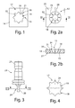
- a countersunk hole 12 in a plate-shaped material 14 which in FIG. 2a in a plan view and in FIG. 2b is shown in a sectional view, an at least two-stage method is used, in accordance with FIG. 1 a pre-hole 16 in the plate-shaped Material 14 is introduced to then increase the pre-hole 16 to the countersunk hole 12 according to the FIGS. 2a and 2b manufacture.
- pre-hole 16 has a star-shaped sectional contour 17, which directed radially outward and preferably evenly distributed over the circumference trained noses 18 which are interconnected by intermediate portions 19.
- the lugs 18 are formed in this embodiment, for example, semicircular or U-shaped, wherein in a U-shaped configuration, the straight leg can also be widened.
- gaps 21 are formed, which interrupt a fictitious circle circumference, along which the respective end face 22 of the intermediate portion 19 extends and which preferably determine the cross section of the opening 16 of the opening.
- the number of distributed over the circumference arranged lugs 18 and the size of the gap 21 may, depending on the material from which the plate-shaped material 14 may be formed from the wall thickness of the plate-shaped material 14, the diameter of the countersunk hole and / or the degree of Countersink 34, which is provided for the countersunk hole 12, are selected and adjusted.
- the intermediate portions 19 forming end faces 22 are preferably convex, that is, that they extend along a common notional circle. Alternatively, it can also be provided that the end faces 22 extend in a straight line between two adjacent lugs 18 or are even curved to the longitudinal center axis of the pilot hole 16.
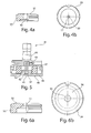
- a pre-punching tool 23 can be used according to a preferred embodiment, which a Vorstanzstempel 24 according to FIG. 3 with a punch cross section according to FIG. 4 and a punching die 25 according to the FIGS. 4a and 4b includes.
- the punching punch 24 comprises a punch shaft 27 and a punching punch 24 arranged integrally thereon or exchangeable therewith Punch 24 has a stamp surface or a cross-sectional area according to FIG. 4 which is a sectional view along the line III-III in FIG. 3 shows.
- FIG. 4 illustrated sectional contour corresponds to in FIG. 1
- the outer contour of the stamp surface or cross-sectional area is consequently formed by the lugs 18 and the intermediate portions arranged therebetween.
- the pre-punching die 25 comprises a through-bore 30 with a cutting contour which is complementary to the pre-punching punch 24 and which adjoins a countersurface 32 for the plate-shaped material 14.
- a countersinking step is carried out with a countersinking tool 41 in order to move into the FIGS. 2a and 2b illustrated countersink 34 with an outer periphery 38 which limits the countersink 34 outwardly to introduce and produce the countersunk hole 12.
- FIG. 5 is schematically shown in partial section, the countersinking tool 41 with an anvil 42.
- the countersinking tool 41 comprises a punch shaft 44, on which the countersinking punch 42 can be fastened interchangeably by means of, for example, a threaded pin 43.
- the counter punch 42 is guided in its mounting region opposite in a bore of a blank holder 46.
- This hold-down 48 is guided by spring elements 47 relatively yielding to the punch shaft 44, so that when applying a compressive force on the hold-down 46 of the counter punch 42 can protrude relative to a contact surface 48 of the blank 46.
- the countersunk punch 42 comprises a precursor tip 49 and an adjoining work surface 51, which merges into a guide shaft 52 in a larger diameter.
- the working surface 51 is conical and comprises an angle of, for example, 90 °.
- the precursor tip 49 is adapted to the diameter of the hole 12 to be produced, so that it can in any case dip into the pre-hole 16 or the passage formed by the end face 22 of the intermediate sections 19.
- the passage of the Vorlochs is equal to or usually larger than the passage of the countersunk hole 12th
- An outer diameter of the working surface 51 on the counter punch 42 is preferably larger than an outer circumference of the star-shaped sectional contour 12 of the punching punch 24, preferably at least 1 mm larger.
- the countersinking tool 41 further comprises a serration 54 having a central passage 55, which in a side view of a schematic partial section in FIG. 6a and in a plan view in FIG FIG. 6b is shown. Adjacent to the passage 55 is provided an anvil surface 56 for the plate-shaped material.
- the countersink 34 is introduced into the pre-hole 16 by means of the countersinking tool 41.
- 16 material is displaced in the edge region of the Vorlochs, that is, that the intermediate portions 19 forming material and the immediately surrounding the nose 18 material is displaced.
- the size of the punch-out of the pilot hole 16 is a function of the material thickness and the degree of countersinking 34 in order to achieve a predefined size of the perforation hole 58 with holes.
- the working surface 51 of the Ansenkstempels 52 is greater than the outer periphery of the star-shaped sectional contour 17, so that a nose surrounding, closed lateral surface 71 is formed, which forms between the top 35 of the plate-shaped material 14 and the upper ends of the lugs 18.
- the in the FIGS. 2a and 2b shown counterbore 34 extends from an upper side 35 of the plate-shaped material 14 to its Bottom 37. In such a case one speaks of a sinking.
- the countersink 34 may also extend only partially from the top side 35 of the plate-shaped material 14 in the direction of the underside 37.
- FIG. 7 a schematic side view of a grading tool 61 is shown.
- This comprises a punch shaft 27 and a flat punch 63 with a flat punch surface 64 and a Flachmatrize 67 with a leveling surface 68.
- This leveling surface 68 is inclined relative to a plane perpendicular to the longitudinal axis or Flachmatrize 67 level at an angle 69, starting from the longitudinal central axis, for example at an angle 69 of less than 5 °, in particular in an angular range of 2 to 0.5 °.
- a leveling of the plate-shaped material 14 is made possible so that any existing distortion is reduced or reversed. Furthermore, by leveling, the top 35 and bottom 37, in particular the adjacent to the countersunk hole 12 edge zone, are smoothed. This leveling step can be carried out additionally.
- the star-shaped sectional contour 17 in FIG. 1 is only an example. Further deviations of the cutting contour may also be conceivable, with all cutting contours maintaining the basic principle that radially outwardly directed lugs 18 are provided, which form interspaces 21 or free spaces, so that the material to be displaced during the countersinking process interspaces 21 fill out and prefers to close completely.
- lugs 18 are suitable for the formation of the lugs 18 round or curved courses, but the noses can also include angular and pointed, radially outward ends.
- FIG. 8 an alternative embodiment for producing a star-shaped sectional contour 17 of the pre-hole 16 is shown.
- This star-shaped sectional contour 17 has lugs 18 with larger gaps 21 than the FIG. 1 so that a larger share of the too displacing material in the spaces 21 can flow.
- a transition region 73 between the lugs 18 may be formed as an intersection in which the lugs 18 directly adjoin one another.
- intermediate sections 19 may also be formed, as shown in FIG FIG. 1 is shown.
- Such a pre-punch hole 16 according to FIG. 8 can with a pre-punch 75 according to the Figures 10a and 10b getting produced.
- This punching punch 75 is analogous to that in FIG. 3 constructed and has a punch shaft 27 and a cutting tool 28.
- This cutting tool 28 comprises an oval or elliptical sectional contour 76, as in FIG FIG. 10b can be seen in the plan view.
- the pre-punching punch 75 cooperates with a pre-punching die 78, which has an opening 30 with a complementary cut-out contour to the punching punch 75.
- This punching die is in FIG. 11 a in a plan view and in FIG. 11 b shown in a side view in partial section.
- the individual lugs 18 can be moved according to FIG FIG. 8 be formed.
- the cutting contour 76 of the punching punch 75 is to form a nose 18 in FIG FIG. 8 shown.
- the cut contour 76 can also be formed only partially elliptical, for example, by extending the contour of a main apex in the direction of the two side vertices, to the two side vertices or beyond.
- the punching punch 75 performs 18 individual punching steps according to the number of required lugs, and is rotated or pivoted in a rotating direction after each single punching step to form the succeeding adjacent lug 18. Once the punching punch 75 has been rotated once through 360 °, the pre-hole 16 is moved according to FIG FIG. 8 educated.
- the Distance of the main vertex of the elliptical sectional contour along the main axis of the elliptical sectional contour 76 extends over the longitudinal center axis of the pilot hole 16, that is, a rotation axis 77 of the ram punch 25 in this case lies on the major axis of the elliptical sectional contour 76 and in the longitudinal axis of the Vorlochs.
- a size of the cut contour 76 it is possible, for example, to introduce the individual punching steps with the punching punch 75 directly into the plate-shaped material 12 without the prior production of a core hole 79.
- a core hole 79 can be introduced before the pre-punching step, which, for example, has a circumference on which the transition regions 73 of the lugs 18 lie.
- the intermediate spaces 19 between the lugs 18 can be made variable.
- the transition region 73 may be formed by intersecting cut lines of the lugs 18.
- larger intermediate portions 19 are formed, as for example in FIG. 1 is shown.
- this method also allows for increased flexibility in the production of the pre-punch holes 16.
- FIGS. 12 and 13 demonstrate.
- a plate-shaped material with a countersunk hole 12 is shown.
- a core hole 79 is shown in this view, which corresponds to the countersunk hole 12 in diameter.
- the distance of the main vertex of the elliptical sectional contour 76 is small, so that a small elliptical sectional contour 76 is formed. In any case, the distance between the main vertices of the elliptical sectional contour 76 is greater than the width of the countersurface 32 projected onto the upper side 32.
- the axis of rotation 77 outside the cutting contour 76 is preferably in the longitudinal axis of the countersunk hole 12
- Outer vertex of the cut contour 76 is guided along the circular path 81, so that a closed lateral surface 71 is formed between this circular path 81 and the outer circumference 38 of the countersink 34.
- a plurality of individual single-step punched rows are provided, wherein the rotation of the cut contour 76 takes place about the longitudinal central axis of the lowered hole 12.
- FIG. 13 is the same size of the countersunk hole 12 as in FIG. 12 shown.
- the cutting tool 28 has a sectional contour 76 which is substantially larger than that of the cutting tool 28 in FIG. 12 is.
- the distance of the main vertex of the elliptical sectional contour 76 from the circular path 81 extends over the Ansenk Chemistry 32 and over the diameter of the core hole 79.
- the axis of rotation 77 of the punching punch 75 is within the cutting contour 76th
- FIGS. 14a to 14c a punching punch 75 is shown with a cutting tool 28 in which the cutting contour 76 of the punching punch 75 has the same size, wherein the size of the countersunk hole 12 of FIG. 14a to FIG. 14c increases.
- a countersunk hole 12 can be introduced into the plate-shaped material 14, which has a smooth top and bottom 35, 37 in particular in the edge region of the countersunk hole 12, without additional punched outs, reworks or other material displacements required are.
Landscapes
- Engineering & Computer Science (AREA)
- Mechanical Engineering (AREA)
- Punching Or Piercing (AREA)
- Drilling And Boring (AREA)
Applications Claiming Priority (1)
| Application Number | Priority Date | Filing Date | Title |
|---|---|---|---|
| DE102014103975.0A DE102014103975B4 (de) | 2014-03-24 | 2014-03-24 | Verfahren, Vorstanzwerkzeug und Planierwerkzeug zur Herstellung von angesenkten Löchern in einem plattenförmigen Material |
Publications (2)
| Publication Number | Publication Date |
|---|---|
| EP2923778A2 true EP2923778A2 (fr) | 2015-09-30 |
| EP2923778A3 EP2923778A3 (fr) | 2016-03-16 |
Family
ID=52780851
Family Applications (1)
| Application Number | Title | Priority Date | Filing Date |
|---|---|---|---|
| EP15160455.0A Withdrawn EP2923778A3 (fr) | 2014-03-24 | 2015-03-24 | Procédé à realiser des trous chanfreinés dans un matériau en forme de plaque |
Country Status (2)
| Country | Link |
|---|---|
| EP (1) | EP2923778A3 (fr) |
| DE (1) | DE102014103975B4 (fr) |
Cited By (1)
| Publication number | Priority date | Publication date | Assignee | Title |
|---|---|---|---|---|
| CN118002691A (zh) * | 2024-04-09 | 2024-05-10 | 江苏南方精工股份有限公司 | 折弯拉伸类产品的冲压方法及模具 |
Citations (4)
| Publication number | Priority date | Publication date | Assignee | Title |
|---|---|---|---|---|
| DE2617231A1 (de) | 1975-04-21 | 1976-11-04 | Ferco Int Usine Ferrures | Verfahren zur herstellung von senkloechern |
| DE2706849A1 (de) | 1976-04-30 | 1977-11-10 | Yoshitaka Nakanishi | Verfahren, presswerkzeug und pressvorrichtung zur herstellung von angesenkten loechern |
| EP0879656A1 (fr) | 1997-05-20 | 1998-11-25 | FERCO INTERNATIONAL Ferrures et Serrures de Bâtiment, Société Anonyme | Outillage pour le faconnege par emboutissage d'un orifice a embouchure tronconique dans un materiau metallique en bande, notamment tetiere |
| AT4432U1 (de) | 1999-04-27 | 2001-07-25 | Hydro Aluminium Komponenten Gm | Verfahren zur herstellung von senklöchern und werkzeug zur ausübung des verfahrens |
Family Cites Families (3)
| Publication number | Priority date | Publication date | Assignee | Title |
|---|---|---|---|---|
| DE3116765C1 (de) * | 1981-04-28 | 1990-10-04 | Rohde & Schwarz GmbH & Co KG, 8000 München | Werkzeug zum Herstellen von Senkloechern oder Passloechern in einem Blech auf einer Stanzmaschine |
| FR2870145B1 (fr) * | 2004-05-11 | 2006-06-23 | Ferco Int Usine Ferrures | Piece metallique avec trou chanfreine, procede et outillage pour le faconnae d'un tel trou chanfreine |
| EP2532452B1 (fr) * | 2011-06-10 | 2014-03-12 | TRUMPF Werkzeugmaschinen GmbH + Co. KG | Procédé de poinçonnage et de dressage de tôles |
-
2014
- 2014-03-24 DE DE102014103975.0A patent/DE102014103975B4/de active Active
-
2015
- 2015-03-24 EP EP15160455.0A patent/EP2923778A3/fr not_active Withdrawn
Patent Citations (4)
| Publication number | Priority date | Publication date | Assignee | Title |
|---|---|---|---|---|
| DE2617231A1 (de) | 1975-04-21 | 1976-11-04 | Ferco Int Usine Ferrures | Verfahren zur herstellung von senkloechern |
| DE2706849A1 (de) | 1976-04-30 | 1977-11-10 | Yoshitaka Nakanishi | Verfahren, presswerkzeug und pressvorrichtung zur herstellung von angesenkten loechern |
| EP0879656A1 (fr) | 1997-05-20 | 1998-11-25 | FERCO INTERNATIONAL Ferrures et Serrures de Bâtiment, Société Anonyme | Outillage pour le faconnege par emboutissage d'un orifice a embouchure tronconique dans un materiau metallique en bande, notamment tetiere |
| AT4432U1 (de) | 1999-04-27 | 2001-07-25 | Hydro Aluminium Komponenten Gm | Verfahren zur herstellung von senklöchern und werkzeug zur ausübung des verfahrens |
Cited By (1)
| Publication number | Priority date | Publication date | Assignee | Title |
|---|---|---|---|---|
| CN118002691A (zh) * | 2024-04-09 | 2024-05-10 | 江苏南方精工股份有限公司 | 折弯拉伸类产品的冲压方法及模具 |
Also Published As
| Publication number | Publication date |
|---|---|
| DE102014103975B4 (de) | 2018-12-20 |
| EP2923778A3 (fr) | 2016-03-16 |
| DE102014103975A1 (de) | 2015-09-24 |
Similar Documents
| Publication | Publication Date | Title |
|---|---|---|
| DE2706849C2 (de) | Verfahren zum Herstellen von konisch angesenkten Durchgangslöchern sowie Preßwerkzeug zur Durchführung des Verfahrens | |
| CH640317A5 (de) | Kreuzschlitzkopfschraube. | |
| EP1705385B1 (fr) | Passage et procédé de fabrication | |
| DE102010061321A1 (de) | Verfahren zum Fräsen einer Ausnehmung in einem Werkstück und Werkstück mit einer Ausnehmung | |
| DE3220461C2 (de) | Vorrichtung zum Einbringen von Löchern in dicke Papierstapel | |
| DE2831012C2 (de) | Nietkörper für einen Heftniet | |
| DE102011001522B4 (de) | Verbindungselement zur Herstellung einer Verbindung zwischen wenigstens zwei sich überlappenden Bauteilen und Verfahren zur Herstellung dieser Verbindung | |
| DE2811567A1 (de) | Bohrschraube sowie verfahren und vorrichtung zu ihrer herstellung | |
| DE10144759A1 (de) | Kombinationswerkzeug | |
| DE69736908T2 (de) | Stanzniet | |
| DE60215113T2 (de) | Stanzwerkzeug | |
| DE2617231A1 (de) | Verfahren zur herstellung von senkloechern | |
| EP3204180B1 (fr) | Outil de perçage, en particulier alésoir | |
| DE102014116988A1 (de) | Verfahren zur Herstellung einer Montageeinheit | |
| WO2022152903A1 (fr) | Rondelle de blocage et son procédé de production, et raccord à vis utilisant une telle rondelle de blocage | |
| EP1892427B1 (fr) | Élément de fixation et procédure de fixation de cet élément de fixation à un élément de tôle metallique | |
| EP2923778A2 (fr) | Procédé à realiser des trous chanfreinés dans un matériau en forme de plaque | |
| EP2915613A1 (fr) | Foret à trou transversal | |
| EP3986633B1 (fr) | Pièce de base destinée à produire un boîtier de cartouche et boîtier de cartouche, procédé de production d'une pièce de base pour un boîtier de cartouche, et procédé de production d'un boîtier de cartouche | |
| EP2848338B1 (fr) | Tête de perçage et foret | |
| DE4303807A1 (de) | Spanlos geformte trichterförmige Durchgangsöffnung | |
| EP3880977B1 (fr) | Rivet auto-perforant | |
| DE102021110729A1 (de) | Selbststanzendes Funktionselement, Zusammenbauteil und Verfahren zum Herstellen eines Zusammenbauteils | |
| DE102008003065B3 (de) | Verfahren zur Herstellung sechseckiger Sicherungsscheiben | |
| DE102017115296A1 (de) | Verfahren zur Herstellung eines Durchzugniets |
Legal Events
| Date | Code | Title | Description |
|---|---|---|---|
| PUAI | Public reference made under article 153(3) epc to a published international application that has entered the european phase |
Free format text: ORIGINAL CODE: 0009012 |
|
| AK | Designated contracting states |
Kind code of ref document: A2 Designated state(s): AL AT BE BG CH CY CZ DE DK EE ES FI FR GB GR HR HU IE IS IT LI LT LU LV MC MK MT NL NO PL PT RO RS SE SI SK SM TR |
|
| AX | Request for extension of the european patent |
Extension state: BA ME |
|
| PUAL | Search report despatched |
Free format text: ORIGINAL CODE: 0009013 |
|
| AK | Designated contracting states |
Kind code of ref document: A3 Designated state(s): AL AT BE BG CH CY CZ DE DK EE ES FI FR GB GR HR HU IE IS IT LI LT LU LV MC MK MT NL NO PL PT RO RS SE SI SK SM TR |
|
| AX | Request for extension of the european patent |
Extension state: BA ME |
|
| RIC1 | Information provided on ipc code assigned before grant |
Ipc: B21D 28/34 20060101ALI20160205BHEP Ipc: B21D 28/26 20060101ALI20160205BHEP Ipc: B21D 22/04 20060101AFI20160205BHEP Ipc: B21D 28/24 20060101ALI20160205BHEP |
|
| 17P | Request for examination filed |
Effective date: 20160916 |
|
| RBV | Designated contracting states (corrected) |
Designated state(s): AL AT BE BG CH CY CZ DE DK EE ES FI FR GB GR HR HU IE IS IT LI LT LU LV MC MK MT NL NO PL PT RO RS SE SI SK SM TR |
|
| STAA | Information on the status of an ep patent application or granted ep patent |
Free format text: STATUS: EXAMINATION IS IN PROGRESS |
|
| 17Q | First examination report despatched |
Effective date: 20180308 |
|
| GRAP | Despatch of communication of intention to grant a patent |
Free format text: ORIGINAL CODE: EPIDOSNIGR1 |
|
| STAA | Information on the status of an ep patent application or granted ep patent |
Free format text: STATUS: GRANT OF PATENT IS INTENDED |
|
| INTG | Intention to grant announced |
Effective date: 20210309 |
|
| STAA | Information on the status of an ep patent application or granted ep patent |
Free format text: STATUS: THE APPLICATION IS DEEMED TO BE WITHDRAWN |
|
| 18D | Application deemed to be withdrawn |
Effective date: 20210720 |