EP2923797A1 - Cloueur à poudre - Google Patents
Cloueur à poudre Download PDFInfo
- Publication number
- EP2923797A1 EP2923797A1 EP14162168.0A EP14162168A EP2923797A1 EP 2923797 A1 EP2923797 A1 EP 2923797A1 EP 14162168 A EP14162168 A EP 14162168A EP 2923797 A1 EP2923797 A1 EP 2923797A1
- Authority
- EP
- European Patent Office
- Prior art keywords
- central axis
- combustion chamber
- slide
- tacker
- piston
- Prior art date
- Legal status (The legal status is an assumption and is not a legal conclusion. Google has not performed a legal analysis and makes no representation as to the accuracy of the status listed.)
- Withdrawn
Links
- 238000002485 combustion reaction Methods 0.000 claims abstract description 41
- 239000003380 propellant Substances 0.000 claims abstract description 11
- 239000007789 gas Substances 0.000 description 5
- 239000000567 combustion gas Substances 0.000 description 3
- 210000000078 claw Anatomy 0.000 description 2
- 239000002737 fuel gas Substances 0.000 description 2
- 238000004873 anchoring Methods 0.000 description 1
- 230000001419 dependent effect Effects 0.000 description 1
- 238000006073 displacement reaction Methods 0.000 description 1
- 238000005553 drilling Methods 0.000 description 1
- 238000012423 maintenance Methods 0.000 description 1
- 239000002184 metal Substances 0.000 description 1
- 238000009527 percussion Methods 0.000 description 1
- 239000013641 positive control Substances 0.000 description 1
- 238000002360 preparation method Methods 0.000 description 1
- 230000001105 regulatory effect Effects 0.000 description 1
- 230000000007 visual effect Effects 0.000 description 1
Images


Classifications
-
- B—PERFORMING OPERATIONS; TRANSPORTING
- B25—HAND TOOLS; PORTABLE POWER-DRIVEN TOOLS; MANIPULATORS
- B25C—HAND-HELD NAILING OR STAPLING TOOLS; MANUALLY OPERATED PORTABLE STAPLING TOOLS
- B25C1/00—Hand-held nailing tools; Nail feeding devices
- B25C1/08—Hand-held nailing tools; Nail feeding devices operated by combustion pressure
- B25C1/10—Hand-held nailing tools; Nail feeding devices operated by combustion pressure generated by detonation of a cartridge
- B25C1/14—Hand-held nailing tools; Nail feeding devices operated by combustion pressure generated by detonation of a cartridge acting on an intermediate plunger or anvil
- B25C1/143—Hand-held nailing tools; Nail feeding devices operated by combustion pressure generated by detonation of a cartridge acting on an intermediate plunger or anvil trigger operated
Definitions
- the invention relates to a tacker according to the preamble of claim 1.
- Hand-held driving devices with propellant charge are known from the prior art, in which after ignition of a pyrotechnic charge, the resulting fuel gases expand in a combustion chamber. As a result, a piston is accelerated as energy transfer means and drives a fastener into a workpiece.
- US 6,321,968 B1 describes a tacker with a propellant charge, in which the combustion chamber is separated by means of a perforated disc in an upper part of the chamber and a lower sub-chamber.
- the tacker has an adjustability of a dead space volume to adjust the Einandergie the device adjustable.
- a valve-like slide can be adjusted in a direction perpendicular to a driving axis.
- the combustion chamber in the closed position of the slide on a dead space, which is formed as a recess in a side wall of the combustion chamber.
- a substantially cylindrical sleeve can be understood as the central axis of completely rotating bodies.
- the piston member may be guided in the slider at least over a first part of its movement.
- a variable release of the Abblaskanals or more Abblaskanäle can be done depending on detail by an adjustment of the slider in an axial direction and / or in the circumferential direction.
- a blow-off channel in the sense of the invention is any space which can be added to the combustion chamber volume by the adjusting member in such a way as to change a driving energy in a defined manner via the additional expansion space.
- the Abblaskanal can be connected to an outside space.
- the blow-off channel may also be a dead space volume not connected to an exterior space.
- a driving energy is understood to mean the kinetic energy of a given fastening element for a given propellant charge. Upon specification of these boundary conditions, it is possible by the actuator to adjust the resulting driving energy of the fastener adjustable.
- a piston member according to the invention is any means that is acted upon by the ignition of the charge with kinetic energy, wherein the kinetic energy is ultimately transmitted to the fastener.
- the piston member is designed as a particular cylindrical piston.
- recesses or other structures may be provided which further promote turbulence and uniform expansion of the fuel gases.
- a central axis in the sense of the invention is an axis at least parallel to the movement of the fastening element, which runs through a center of the combustion chamber.
- the central axis extends through both the center of the combustion chamber and through a center of the fastener.
- any retractable anchoring such as nail, bolt or screw understood.
- the slide has a preferably cylindrical inner wall, which is formed as part of the combustion chamber.
- the slide is also useful a guide of the piston member in a first portion of the piston movement.
- the actuator has a pivotable about the central axis control panel.
- the control panel may be any suitable means for manual adjustment, such as a rotatable sleeve as a particularly preferred variant, a pivotable knob or the like.
- the operating part is designed as an annular sleeve, wherein the sleeve surrounds the central axis.
- the sleeve can be rotated in several different positions, wherein at least two different positions are assigned to two different drive energies.
- the sleeve can be held by means of a locking member in at least one defined position.
- Such defined positions may be a maintenance position or a defined position for changing the driving energy.
- An inventive control panel and in particular a sleeve described above can be arranged to optimize the ergonomics of the device in a front area in front of a handle of the device.
- an advantageous analogy to known controls of hand-held Drilling machines and / or cordless screwdrivers result.
- the controls of such devices are used according to other purposes, such as a torque adjustment or a change from screwing to hammer operation in a percussion drill.
- a pivoting of the operating part about the central axis means a substantially perpendicular to the axis oriented deflection of the control panel from a previous position.
- a movement line or trajectory of the operating part has a radius of curvature, which is preferably not smaller than a distance of the operating part from the central axis.
- the pivoting is a rotation about the central axis.
- control panel and the slider are rotatably connected, so that a rotation of the control panel at the same time causes a rotation and adjustment of the slider for regulating the driving energy.
- a piston guide arranged in front of the combustion chamber is received rotatably relative to the housing about the central axis.
- the piston guide and the slide are particularly non-rotatably coupled to each other and axially movable relative to one another.
- the piston guide fulfills an additional function as a mechanical link between the slider and a control panel.
- the slider has a collar which runs around the central axis and overlaps into a recess of a combustion chamber housing, wherein at least part of the blow-off channel is formed as an axially extending recess between the collar and the combustion chamber housing.
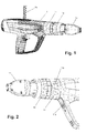
- a drive-in device comprises a hand-guided housing 1, in which a piston member in the form of a piston 2 is accommodated.
- a surface 2a of the piston 2 defines a combustion chamber 3 in which the combustion gases of a pyrotechnic charge expand to accelerate the piston 2.
- the fastening element may in particular be accommodated in a module or magazine (not shown) that is interchangeable in a front holding region 1a of the tacker device 1.
- the charge is presently received in a cartridge 4a made of sheet metal.
- the cartridge 4a has an impact fuse and is inserted into a cartridge bearing 4 before ignition via a corresponding loading mechanism, in the present case by means of a magazine strip.
- the cartridge and the cartridge bearing 4 are rotationally symmetrical about one Central axis A formed.
- the central axis A is in the present examples at the same time a central axis of the combustion chamber 3 and the piston member. 2
- the combustion chamber 3 is formed in a first section as a hollow cylindrical, substantially sleeve-shaped body 6.
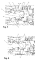
- This body 6 is at the same time as a rotatable about the central axis A and thereby in its position in the direction of the central axis A variable slide for adjustable release of one or more Abblaskanäle 7 formed with, for example, stepped cross-section.
- the exhaust duct 7 comprises a plurality of recesses 7a in a combustion chamber housing 8 distributed over the circumference.
- the recesses 7a extend axially in the direction parallel to the central axis A and open into a section of the exhaust duct 7 with a larger volume running between the combustion chamber housing 8 and a piston guide 5.
- a cylindrical recess with a multi-start internal thread 8a In the combustion chamber housing 8 is located in the region of the combustion chamber, a cylindrical recess with a multi-start internal thread 8a.
- the slider 6 is screwed with a corresponding external thread 6a in the opening of the combustion chamber housing 8. A rotation of the slider 6 about the central axis A thus causes a positively controlled axial displacement of the slider. 6
- the slide 6 is provided with a collar 6b which extends to the rear or in the direction of a bottom of the combustion chamber 3 and engages in the recess of the combustion-chamber housing 8 in an axially overlapping manner.
- a variable passage 9 is thus released from the combustion chamber 3 into the recesses or blow-off channels 7a (see FIG Fig. 5 ).
- the passage 9 is closed when completely displaced to the rear slider 6 (see Fig. 6 ). If an opened passage 9 is set, then this is a part of the blow-off duct 7a, 7.
- the passage is arranged in the axial direction immediately in front of the bottom of the combustion chamber 3, so that combustion gases can escape into the blow-off duct immediately at the beginning of the piston movement. hereby Depending on the setting of the slide 6, a particularly large area of energy reduction can be achieved.
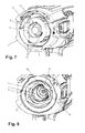
- a front end of the piston guide 5 is rotatably coupled to a control panel 10. so that the piston guide 5 at the same time forms a mechanical connection between the operating part 10 and the slide 6.
- the operating part 10 is designed as a sleeve rotatable in the combustion chamber housing, which sleeve is arranged substantially concentrically around the central axis A in a front region of the housing 1 of the tacking device.
- the operating part 10 together with the piston guide 5 and the slide 6, an actuator for changing the driving force of the tacker 1 from.
- This adjustment and the drive operation work as follows:
- the piston member After a Eintreibvorgang the piston member is in a partially undefined, but largely shifted forward position.
- the combustion chamber housing 8 is located in a maximally pushed back into the tacker in position.
- front and rear are always selected with reference to the driving direction.
- the desired driving energy is set as the energy level marked on the operating part by rotating the sleeve 10. This leads via the positive control described above to a selected axial positioning of the slide 6 relative to the combustion chamber housing 8. As a result, the blow-off channel is released or closed defined via the passage 9 (maximum driving energy).
- a corresponding part of the propellant gases or exhaust gases is discharged to the outside via the described channels 7a, 7.
- a closed dead space volume may be provided, for example, the Abblaskanäle 7a serve only as an optional room extension of the combustion chamber and are not connected further to the outside.
- the gases guided via the blow-off ducts are used for a piston return by means of gas pressure.
- a disassembly of the piston member 2 and the combustion chamber housing 8 by means of an additional locking ring 11 is made possible, which is arranged behind the control unit 10.
- the lock ring carries a button 10a, which serves to secure the control panel 10 and must be pressed to adjust the control panel.
- the locking ring 11 is secured in a similar manner via a button 11 a to the housing of the tacker 1.
- the above-mentioned function for disassembling the tacker can also be integrated into the operating part 10.
Landscapes
- Engineering & Computer Science (AREA)
- Chemical & Material Sciences (AREA)
- Combustion & Propulsion (AREA)
- Mechanical Engineering (AREA)
- Portable Nailing Machines And Staplers (AREA)
Priority Applications (9)
| Application Number | Priority Date | Filing Date | Title |
|---|---|---|---|
| EP14162168.0A EP2923797A1 (fr) | 2014-03-28 | 2014-03-28 | Cloueur à poudre |
| JP2016555808A JP6298900B2 (ja) | 2014-03-28 | 2015-03-24 | 発射薬式打込装置 |
| ES15711764.9T ES2669497T3 (es) | 2014-03-28 | 2015-03-24 | Aparato de inserción pirotécnica |
| AU2015238461A AU2015238461A1 (en) | 2014-03-28 | 2015-03-24 | Pyrotechnic driving device |
| EP15711764.9A EP3122515B1 (fr) | 2014-03-28 | 2015-03-24 | Cloueur à poudre |
| TR2018/10062T TR201810062T4 (tr) | 2014-03-28 | 2015-03-24 | Piroteknik çakma aleti. |
| US15/122,966 US10500703B2 (en) | 2014-03-28 | 2015-03-24 | Pyrotechnic driving device |
| PCT/EP2015/056226 WO2015144687A1 (fr) | 2014-03-28 | 2015-03-24 | Dispositif d'enfoncement pyrotechnique |
| CN201580012645.XA CN106103001B (zh) | 2014-03-28 | 2015-03-24 | 烟火技术的击入设备 |
Applications Claiming Priority (1)
| Application Number | Priority Date | Filing Date | Title |
|---|---|---|---|
| EP14162168.0A EP2923797A1 (fr) | 2014-03-28 | 2014-03-28 | Cloueur à poudre |
Publications (1)
| Publication Number | Publication Date |
|---|---|
| EP2923797A1 true EP2923797A1 (fr) | 2015-09-30 |
Family
ID=50389300
Family Applications (2)
| Application Number | Title | Priority Date | Filing Date |
|---|---|---|---|
| EP14162168.0A Withdrawn EP2923797A1 (fr) | 2014-03-28 | 2014-03-28 | Cloueur à poudre |
| EP15711764.9A Active EP3122515B1 (fr) | 2014-03-28 | 2015-03-24 | Cloueur à poudre |
Family Applications After (1)
| Application Number | Title | Priority Date | Filing Date |
|---|---|---|---|
| EP15711764.9A Active EP3122515B1 (fr) | 2014-03-28 | 2015-03-24 | Cloueur à poudre |
Country Status (8)
| Country | Link |
|---|---|
| US (1) | US10500703B2 (fr) |
| EP (2) | EP2923797A1 (fr) |
| JP (1) | JP6298900B2 (fr) |
| CN (1) | CN106103001B (fr) |
| AU (1) | AU2015238461A1 (fr) |
| ES (1) | ES2669497T3 (fr) |
| TR (1) | TR201810062T4 (fr) |
| WO (1) | WO2015144687A1 (fr) |
Cited By (2)
| Publication number | Priority date | Publication date | Assignee | Title |
|---|---|---|---|---|
| EP4067002A1 (fr) * | 2021-03-29 | 2022-10-05 | Hilti Aktiengesellschaft | Appareil d'enfoncement pyrotechnique |
| US12296452B2 (en) | 2021-03-29 | 2025-05-13 | Hilti Aktiengesellschaft | Pyrotechnic driving device |
Families Citing this family (3)
| Publication number | Priority date | Publication date | Assignee | Title |
|---|---|---|---|---|
| EP2886260A1 (fr) * | 2013-12-19 | 2015-06-24 | HILTI Aktiengesellschaft | Appareil d'enfoncement |
| EP2923797A1 (fr) * | 2014-03-28 | 2015-09-30 | HILTI Aktiengesellschaft | Cloueur à poudre |
| EP2923800A1 (fr) * | 2014-03-28 | 2015-09-30 | HILTI Aktiengesellschaft | Cloueur à poudre |
Citations (6)
| Publication number | Priority date | Publication date | Assignee | Title |
|---|---|---|---|---|
| DE1478826A1 (de) * | 1963-11-26 | 1969-01-23 | Bettermann Elektro Ohg | Bolzenschiessgeraet |
| US4119257A (en) * | 1975-07-02 | 1978-10-10 | Societe De Prospection Et D'inventions Techniques Spit | Power actuated tools |
| US4153192A (en) * | 1977-03-02 | 1979-05-08 | Hilti Aktiengesellschaft | Control member for fastening element setting device |
| GB2074704A (en) * | 1980-04-28 | 1981-11-04 | Hilti Ag | Explosive-powered fastener-driving tool |
| EP0788863A1 (fr) * | 1996-02-09 | 1997-08-13 | Illinois Tool Works Inc. | Outil de fixation entraîné par gaz de combustion |
| US6321968B1 (en) | 1998-09-10 | 2001-11-27 | Senco Products, Inc. | Combustion chamber design for propellant charges and power adjustment means |
Family Cites Families (33)
| Publication number | Priority date | Publication date | Assignee | Title |
|---|---|---|---|---|
| US3549074A (en) * | 1968-05-01 | 1970-12-22 | Olin Mathieson | Power adjustment for piston tool |
| CH562665A5 (fr) * | 1972-08-07 | 1975-06-13 | Olin Authier Sa | |
| MX143926A (es) * | 1975-07-02 | 1981-08-04 | Prospection & Inventions | Mejoras en herramienta fijadora de tapones |
| DE2548014C2 (de) * | 1975-10-27 | 1984-01-12 | Hilti AG, 9494 Schaan | Pulverkraftbetriebenes Setzgerät mit Leistungsregulierung |
| US4358041A (en) * | 1980-06-12 | 1982-11-09 | Olin Corporation | Powder-actuated tool with power adjustment and angle-fire control |
| DE3418238A1 (de) * | 1984-05-16 | 1985-11-21 | Hilti Ag, Schaan | Pulverkraftbetriebenes setzgeraet |
| DE3427616A1 (de) * | 1984-07-26 | 1986-01-30 | Hilti Ag, Schaan | Pulverkraftbetriebenes bolzensetzgeraet |
| DE3806834A1 (de) * | 1988-03-03 | 1989-09-14 | Hilti Ag | Pulverkraftbetriebenes setzgeraet |
| US5029744A (en) * | 1990-06-13 | 1991-07-09 | Hsin-Ho Mfg. Co. Ltd. | Mechanism for controlling the powder impact force on a projectile |
| AUPM948894A0 (en) * | 1994-11-17 | 1994-12-08 | Ramset Fasteners (Aust.) Pty. Limited | Power actuated fastening tool |
| US5722578A (en) * | 1995-09-29 | 1998-03-03 | Illinois Tool Works Inc. | High velocity, combustion-powered, fastener-driving tool |
| AUPN585495A0 (en) * | 1995-10-09 | 1995-11-02 | Ramset Fasteners (Aust.) Pty. Limited | Power actuated tools with power adjustment means |
| DE19544104A1 (de) * | 1995-11-27 | 1997-05-28 | Hilti Ag | Pulverkraftbetriebenes Setzgerät |
| DE19547859A1 (de) * | 1995-12-21 | 1997-06-26 | Hilti Ag | Pulverkraftbetriebenes Setzgerät |
| DE19617671C1 (de) * | 1996-05-03 | 1997-10-09 | Beto Tornado Gmbh | Pulverkraftbetriebenes Bolzensetzgerät |
| US5699948A (en) * | 1996-12-16 | 1997-12-23 | Lee; Cheng-Ho | Adjusting means for use in a staple gun |
| US6364190B1 (en) * | 2000-01-20 | 2002-04-02 | Jamerco, Inc. | Fastener driving tool with twist actuation |
| DE10260702B4 (de) * | 2002-12-23 | 2014-01-30 | Hilti Aktiengesellschaft | Brennkraftbetriebenes Setzgerät |
| US8002160B2 (en) * | 2004-08-30 | 2011-08-23 | Black & Decker Inc. | Combustion fastener |
| DE102005000032A1 (de) * | 2005-04-12 | 2006-10-19 | Hilti Ag | Brennkraftbetriebenes Setzgerät |
| US20080251561A1 (en) * | 2007-04-13 | 2008-10-16 | Chad Eades | Quick connect base plate for powder actuated tool |
| AU2009337197B2 (en) * | 2008-12-24 | 2013-11-28 | Globalforce Ip Limited | Adjustable dose chamber |
| TWM362088U (en) * | 2009-04-09 | 2009-08-01 | Cheng-Ho Lee | Gunpowder nail-hitting apparatus capable of adjusting nail-hitting force |
| CN102120323A (zh) * | 2010-01-08 | 2011-07-13 | 上海林荣金属制品有限公司 | 无击发药无壳弹用的射钉器 |
| DE102010044011A1 (de) * | 2010-11-16 | 2012-05-16 | Hilti Aktiengesellschaft | Handwerkzeugmaschine |
| JP5391244B2 (ja) * | 2011-08-02 | 2014-01-15 | 株式会社スギノマシン | 流体圧式送り速度制御装置 |
| EP2875903A1 (fr) * | 2013-11-26 | 2015-05-27 | HILTI Aktiengesellschaft | Cloueur à poudre |
| EP2886259A1 (fr) * | 2013-12-18 | 2015-06-24 | HILTI Aktiengesellschaft | Appareil d'enfoncement |
| EP2886258A1 (fr) * | 2013-12-18 | 2015-06-24 | HILTI Aktiengesellschaft | Appareil d'enfoncement |
| EP2886257A1 (fr) * | 2013-12-18 | 2015-06-24 | HILTI Aktiengesellschaft | Appareil d'enfoncement |
| EP2886260A1 (fr) * | 2013-12-19 | 2015-06-24 | HILTI Aktiengesellschaft | Appareil d'enfoncement |
| EP2923799A1 (fr) * | 2014-03-28 | 2015-09-30 | HILTI Aktiengesellschaft | Appareil d'enfoncement |
| EP2923797A1 (fr) * | 2014-03-28 | 2015-09-30 | HILTI Aktiengesellschaft | Cloueur à poudre |
-
2014
- 2014-03-28 EP EP14162168.0A patent/EP2923797A1/fr not_active Withdrawn
-
2015
- 2015-03-24 ES ES15711764.9T patent/ES2669497T3/es active Active
- 2015-03-24 CN CN201580012645.XA patent/CN106103001B/zh active Active
- 2015-03-24 WO PCT/EP2015/056226 patent/WO2015144687A1/fr not_active Ceased
- 2015-03-24 US US15/122,966 patent/US10500703B2/en active Active
- 2015-03-24 JP JP2016555808A patent/JP6298900B2/ja active Active
- 2015-03-24 AU AU2015238461A patent/AU2015238461A1/en not_active Abandoned
- 2015-03-24 EP EP15711764.9A patent/EP3122515B1/fr active Active
- 2015-03-24 TR TR2018/10062T patent/TR201810062T4/tr unknown
Patent Citations (6)
| Publication number | Priority date | Publication date | Assignee | Title |
|---|---|---|---|---|
| DE1478826A1 (de) * | 1963-11-26 | 1969-01-23 | Bettermann Elektro Ohg | Bolzenschiessgeraet |
| US4119257A (en) * | 1975-07-02 | 1978-10-10 | Societe De Prospection Et D'inventions Techniques Spit | Power actuated tools |
| US4153192A (en) * | 1977-03-02 | 1979-05-08 | Hilti Aktiengesellschaft | Control member for fastening element setting device |
| GB2074704A (en) * | 1980-04-28 | 1981-11-04 | Hilti Ag | Explosive-powered fastener-driving tool |
| EP0788863A1 (fr) * | 1996-02-09 | 1997-08-13 | Illinois Tool Works Inc. | Outil de fixation entraîné par gaz de combustion |
| US6321968B1 (en) | 1998-09-10 | 2001-11-27 | Senco Products, Inc. | Combustion chamber design for propellant charges and power adjustment means |
Cited By (5)
| Publication number | Priority date | Publication date | Assignee | Title |
|---|---|---|---|---|
| EP4067002A1 (fr) * | 2021-03-29 | 2022-10-05 | Hilti Aktiengesellschaft | Appareil d'enfoncement pyrotechnique |
| WO2022207326A1 (fr) * | 2021-03-29 | 2022-10-06 | Hilti Aktiengesellschaft | Outil d'entraînement pyrotechnique |
| CN116940443A (zh) * | 2021-03-29 | 2023-10-24 | 喜利得股份公司 | 烟火驱动装置 |
| US12296452B2 (en) | 2021-03-29 | 2025-05-13 | Hilti Aktiengesellschaft | Pyrotechnic driving device |
| US12415260B2 (en) | 2021-03-29 | 2025-09-16 | Hilti Aktiengesellschaft | Pyrotechnic driving device |
Also Published As
| Publication number | Publication date |
|---|---|
| EP3122515A1 (fr) | 2017-02-01 |
| US10500703B2 (en) | 2019-12-10 |
| ES2669497T3 (es) | 2018-05-28 |
| CN106103001B (zh) | 2018-07-17 |
| JP2017509496A (ja) | 2017-04-06 |
| AU2015238461A1 (en) | 2016-08-18 |
| EP3122515B1 (fr) | 2018-05-02 |
| US20170100830A1 (en) | 2017-04-13 |
| TR201810062T4 (tr) | 2018-08-27 |
| JP6298900B2 (ja) | 2018-03-20 |
| WO2015144687A1 (fr) | 2015-10-01 |
| CN106103001A (zh) | 2016-11-09 |
Similar Documents
| Publication | Publication Date | Title |
|---|---|---|
| EP2140976B1 (fr) | Vis autotaraudeuse à frapper | |
| EP3122515B1 (fr) | Cloueur à poudre | |
| EP1813393B1 (fr) | Outil de scellement | |
| DE102004050076B4 (de) | Pneumatisch betriebenes Elektrowerkzeug mit einem Mechanismus zum Ändern des Druckluftdrucks | |
| DE3690814C2 (de) | Pneumatische Vorrichtung f}r einmalige Schl{ge | |
| AT511810B1 (de) | Schlagwerk für eine hammereinrichtung und verfahren zum offenstellen einer abstichöffnung | |
| DE2326171A1 (de) | Schlagschrauber | |
| EP1712334B1 (fr) | Appareil de scellement à combustion | |
| EP3083154A1 (fr) | Outil d'enfoncement | |
| EP3122516B1 (fr) | Cloueur à poudre | |
| EP4313492B1 (fr) | Appareil d'enfoncement pyrotechnique | |
| EP4313491B1 (fr) | Appareil d'enfoncement pyrotechnique | |
| EP3083153B1 (fr) | Appareil d'enfoncement | |
| DE1949415A1 (de) | Mechanisch getriebene Werkzeugmaschine | |
| EP3393718B1 (fr) | Outil de scellement a moteur thermique et procede de fonctionnement d'un outil de scellement | |
| DE102016121070B4 (de) | Verstellbare Gasabnahmeanordnung für eine Gasdrucklader-Schusswaffe | |
| DE2556616A1 (de) | Schlagwerkzeug | |
| DE10306880A1 (de) | Brennkraftbetriebenes Setzgerät | |
| EP2886256A1 (fr) | Appareil de pose | |
| EP2923798A1 (fr) | Cloueur à poudre | |
| DE102014227040A1 (de) | Druckluftschlagschrauber mit integriertem Axial-Schlagwerk | |
| DE2253032B2 (de) | Drehschlagkupplung in einem druckmittelbetriebenen Schrauber | |
| DE102009016946A1 (de) | Brennkraftgetriebenes Setzgerät |
Legal Events
| Date | Code | Title | Description |
|---|---|---|---|
| PUAI | Public reference made under article 153(3) epc to a published international application that has entered the european phase |
Free format text: ORIGINAL CODE: 0009012 |
|
| AK | Designated contracting states |
Kind code of ref document: A1 Designated state(s): AL AT BE BG CH CY CZ DE DK EE ES FI FR GB GR HR HU IE IS IT LI LT LU LV MC MK MT NL NO PL PT RO RS SE SI SK SM TR |
|
| AX | Request for extension of the european patent |
Extension state: BA ME |
|
| STAA | Information on the status of an ep patent application or granted ep patent |
Free format text: STATUS: THE APPLICATION IS DEEMED TO BE WITHDRAWN |
|
| 18D | Application deemed to be withdrawn |
Effective date: 20160331 |