EP2886257A1 - Appareil d'enfoncement - Google Patents
Appareil d'enfoncement Download PDFInfo
- Publication number
- EP2886257A1 EP2886257A1 EP13198042.7A EP13198042A EP2886257A1 EP 2886257 A1 EP2886257 A1 EP 2886257A1 EP 13198042 A EP13198042 A EP 13198042A EP 2886257 A1 EP2886257 A1 EP 2886257A1
- Authority
- EP
- European Patent Office
- Prior art keywords
- actuator
- piston member
- combustion chamber
- tacker
- propellant charge
- Prior art date
- Legal status (The legal status is an assumption and is not a legal conclusion. Google has not performed a legal analysis and makes no representation as to the accuracy of the status listed.)
- Withdrawn
Links
- 238000002485 combustion reaction Methods 0.000 claims abstract description 66
- 239000003380 propellant Substances 0.000 claims abstract description 42
- 238000005192 partition Methods 0.000 claims description 10
- 230000005540 biological transmission Effects 0.000 claims 1
- 239000002737 fuel gas Substances 0.000 description 11
- 239000000843 powder Substances 0.000 description 11
- 239000002245 particle Substances 0.000 description 10
- 239000000567 combustion gas Substances 0.000 description 5
- 230000000694 effects Effects 0.000 description 5
- 230000001133 acceleration Effects 0.000 description 4
- 230000008859 change Effects 0.000 description 4
- 230000007246 mechanism Effects 0.000 description 4
- 238000005520 cutting process Methods 0.000 description 3
- 238000013461 design Methods 0.000 description 3
- 239000007789 gas Substances 0.000 description 3
- 230000009467 reduction Effects 0.000 description 3
- 230000001953 sensory effect Effects 0.000 description 2
- 238000003860 storage Methods 0.000 description 2
- 230000009471 action Effects 0.000 description 1
- 238000004873 anchoring Methods 0.000 description 1
- 230000008878 coupling Effects 0.000 description 1
- 238000010168 coupling process Methods 0.000 description 1
- 238000005859 coupling reaction Methods 0.000 description 1
- 230000003247 decreasing effect Effects 0.000 description 1
- 230000001419 dependent effect Effects 0.000 description 1
- 238000006073 displacement reaction Methods 0.000 description 1
- 238000009826 distribution Methods 0.000 description 1
- 239000000835 fiber Substances 0.000 description 1
- 230000005484 gravity Effects 0.000 description 1
- 230000012447 hatching Effects 0.000 description 1
- 238000009434 installation Methods 0.000 description 1
- 239000007788 liquid Substances 0.000 description 1
- 238000012423 maintenance Methods 0.000 description 1
- 239000002184 metal Substances 0.000 description 1
- 239000000203 mixture Substances 0.000 description 1
- 230000004048 modification Effects 0.000 description 1
- 238000012986 modification Methods 0.000 description 1
- 238000005457 optimization Methods 0.000 description 1
- 230000002265 prevention Effects 0.000 description 1
- 230000004044 response Effects 0.000 description 1
- 230000000717 retained effect Effects 0.000 description 1
- 239000007787 solid Substances 0.000 description 1
- 238000012546 transfer Methods 0.000 description 1
- 238000011144 upstream manufacturing Methods 0.000 description 1
Images

Classifications
-
- B—PERFORMING OPERATIONS; TRANSPORTING
- B25—HAND TOOLS; PORTABLE POWER-DRIVEN TOOLS; MANIPULATORS
- B25C—HAND-HELD NAILING OR STAPLING TOOLS; MANUALLY OPERATED PORTABLE STAPLING TOOLS
- B25C1/00—Hand-held nailing tools; Nail feeding devices
- B25C1/08—Hand-held nailing tools; Nail feeding devices operated by combustion pressure
- B25C1/10—Hand-held nailing tools; Nail feeding devices operated by combustion pressure generated by detonation of a cartridge
- B25C1/14—Hand-held nailing tools; Nail feeding devices operated by combustion pressure generated by detonation of a cartridge acting on an intermediate plunger or anvil
- B25C1/143—Hand-held nailing tools; Nail feeding devices operated by combustion pressure generated by detonation of a cartridge acting on an intermediate plunger or anvil trigger operated
Definitions
- the invention relates to a tacker according to the preamble of claim 1 and to a system for driving a fastener into a workpiece according to the features of claim 10.
- Hand-held driving devices with propellant charge are known from the prior art, in which after ignition of a pyrotechnic charge, the resulting fuel gases expand in a combustion chamber. As a result, a piston is accelerated as energy transfer means and drives a fastener into a workpiece. Basically, the most optimized, residue-free and reproducible burning of the charge is desired. It should be noted that the charge usually includes particles such as powder grains, fibers or the like, which are initially driven after ignition in front of a flame front ago.
- US 6,321,968 B1 describes a tacker with a propellant charge, in which the combustion chamber is separated by means of a perforated disc in an upper part of the chamber and a lower sub-chamber. Powder grains of the propellant charge are larger than the holes of the disc. Thus, the powder grains are first accelerated in a central discharge area on the perforated portions of the cutting wheel, where they are retained due to the dimensioning of the holes of the cutting wheel, so that a combustion of the powder grains takes place predominantly in the upper part of the chamber.
- Fig. 10 a modification is shown in which a propellant charge without a cartridge is used.
- no design including the central axis enclosing discharge area in the upper part of the chamber is provided, which extends between the propellant charge and a central region of the cutting disc.
- the ejection area in the example of Fig. 10 therefore, does not include the central axis of the combustion chamber, but is annularly arranged around a central plunger of the combustion chamber. The ignition of the cartridge-free charge takes place at an upper end of the central punch.
- the US 6,321,968 B1 shows an adjustability of a dead space volume in order to adjustably change the driving energy of the device.
- a valve-like slide can be adjusted in a direction perpendicular to a driving axis.
- the combustion chamber in the closed position of the slide on a dead space which is formed as a recess in a side wall of the combustion chamber.
- a blow-off channel in the sense of the invention is understood to mean a duct by means of which the combustion gases of the propellant charge are discharged into the environment or into another large volume, for example a gas reservoir for a piston return.
- the piston member is defined by the same slide, which controls the blower, defined against a rearmost position. In such a position, a larger output volume of the combustion chamber is created compared to a rearmost position of the piston member. Furthermore, the concept of the remaining acceleration path of the piston member is shortened by the idea.
- a driving energy is understood to mean the kinetic energy of the piston member impinging on a given fastening means for a given propellant charge. Given these boundary conditions, it is possible by the actuator to adjust the resulting driving energy for the fastener adjustably.
- a piston member according to the invention is any means which is acted upon by the ignition of the charge with kinetic energy, wherein the kinetic energy is ultimately transferred to the fastening means.
- the piston member is designed as a particular cylindrical piston.
- recesses or other structures may be provided which further promote turbulence and uniform expansion of the fuel gases.
- any retractable anchoring such as nail, bolt or screw understood.
- a central axis in the sense of the invention is an axis at least parallel to the movement of the fastening element, which runs in particular through a center of the combustion chamber.
- the slider is movable parallel to the axis, whereby a simple and effective mechanical realization is possible.
- the slider is movable transversely to the axis, preferably perpendicular to the axis.
- an outlet cross-section of the Abblaskanals is adjustable depending on the position of the slide continuously or stepwise changeable.
- a drive-in device in a generally advantageous manner that the release of the blow-off duct and the starting position of the piston member can be set independently of one another. Thereby, any combination of the energy-reducing effects of the actuators can be made, so that a good accuracy of adjustment over a particularly large range of driving energy is available.
- each of the actuators may have a separate adjusting wheel or other operating means.
- a mechanical coupling of the actuators may be present, for example via a shift gate, a gear, a linkage or the like. This allows a functionally linked adjustment of both actuators via only one operating means, which may mean a simplification for the operator.
- the actuators can be adjusted via electrically operated actuators.
- an accurate energy adjustment by an electronic device control done, for example, in response to sensor signals.
- arbitrary combinations of positions of the two actuators can be stored in a map.
- the second actuator comprises an adjustable stop member, wherein the starting position of the piston member is defined by contact of the piston member to the stop member.
- the piston member can be moved in the course of an automatic or manually initiated return operation to the abutment against the stop member.
- the stop member may be formed as projecting into the combustion chamber rod which abuts against a bottom of the piston member. In other embodiments, the stop member may also act against a stop formed outside the combustion chamber of the piston member.
- the combustion chamber is subdivided into a first partial chamber adjoining the propellant and at least one second partial chamber adjoining the piston member by means of a divider having a plurality of openings, wherein an ejection area for the propellant charge is provided in the first sub-chamber, which extends between the propellant charge and a central region of the separator.
- the ejection area preferably includes the central axis, that is, the central axis passes through the ejection area.
- the discharge area at the central area of the separating member is particularly preferably limited by a closed surface of the separating member.
- An ejection region in the sense of the invention is a prismatic, mostly cylindrical spatial region whose cross-section is defined by a surface of the igniting charge directed into the combustion chamber and which extends perpendicular to the surface.
- the surface of the charge is defined herein as the exit surface of the opened cartridge.
- the discharge area is substantially cylindrically shaped. Its diameter corresponds to the inner diameter of the cartridge bearing at its output towards the piston member.
- the central axis according to the invention runs as a center of gravity line through the ejection area. Regularly, but not necessarily, the central axis coincides with a movement axis of the piston member.
- An isolator in the context of the invention is any structure by which the combustion chamber is divided into two sub-chambers.
- the separating member extends transversely to the central axis. It can be designed, for example, as a multi-perforated disc.
- the central region of the separating member is preferably not pierced, so that at least a significant portion of the initially ejected particles moves within the ejection region through the first combustion chamber against the central region, without first entering through the separating member in the second sub-chamber.
- the closed surface of the central area is larger than a sectional area of the partition member with the ejection area.
- the central portion of the partition member has a recess. Through this depression, a particularly good backscattering of the deflected particles and turbulence of combustion gases in the first sub-chamber can take place.
- the depression is formed as a cup-shaped recess in the separating member. This favors a scattering and turbulence in particular.
- an upstanding projection is formed in a central bottom portion of the recess.
- the projection may be conical, for example.
- the recess has a downwardly decreasing diameter, which also causes a good distribution of powder grains and fuel gases.
- a maximum diameter of the depression which is perpendicular to the central axis, is not less than 80% of a maximum diameter of an opening of the propellant charge, which is perpendicular to the axis.
- the diameter of the recess is greater than the diameter of the opening of the propellant charge.
- a maximum depth of the recess measured in the direction of the axis is not less than 30%, more preferably not less than 50% of a maximum diameter of the recess measured perpendicular to the axis is.
- a web is provided in each case between two adjacent apertures, fuel gases of the propellant charge first of all flowing radially outward from the ejection region between the webs, before they flow through the apertures in the axial direction after a deflection.
- the deflection and turbulence of the fuel gases is further optimized, and undesired entry of large grains of powder into the openings is further reduced.
- the openings of the separating member have a cross section which is greater than a maximum cross section of particles of the propellant charge. This prevents clogging of the breakthrough with combustion residues. Due to the further features of the invention, an entry of large powder grains in the second sub-chamber is largely avoided despite relatively large openings.
- the partition member is preferably screwed by means of an external thread formed in it in the combustion chamber.
- a maximum driving energy which can be set by means of the actuator corresponds to at least twice a minimum driving energy which can be set by means of the actuator.
- the maximum driving energy is at least 2.5 times the minimum driving energy.
- the minimum driving energy is not more than 150 joules and the maximum driving energy is not less than 250 joules.
- an at least partially automatic adjustment of the drive-in energy can take place by means of electronic device control.
- necessary specifications for example on the nature and dimensions of the workpiece, can be made by an operator.
- sensory information for example about the type of fastener inserted, can be used.
- a driving tool according to the invention makes it possible to cover a large range of driving forces with only one propellant charge. Accordingly, it can be dispensed with the offer of other propellant charges for the operation of the device.
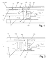
- a drive-in device comprises a hand-guided housing in which a piston member in the form of a piston 2 is accommodated.
- a surface 2a of the piston 2 defines a combustion chamber 3 in which the combustion gases of a pyrotechnic charge expand to accelerate the piston 2.
- the pyrotechnic charge is solid, preferably in powder form. In non-illustrated embodiments, the pyrotechnic charge is liquid or gaseous.
- the charge is presently received in a cartridge made of sheet metal.
- the cartridge has an impact fuze and is inserted into a cartridge bearing 4 before ignition via a corresponding loading mechanism.
- Cartridge and cartridge bearings are preferably formed rotationally symmetrical about a central axis A.
- the central axis A is at the same time a center axis of the combustion chamber 3 and the piston 2 in the present examples.
- the combustion chamber 3 is arranged between a circular opening 4a of the cartridge bearing 4 and the surface 2a of the piston 2.
- an annular recess 2b is formed in the piston 2, which contributes to a better turbulence of the combustion gases and forms part of the combustion chamber 3.
- the combustion chamber 3 in the present case has a side wall 101, which is designed as a rotation surface of a parallel about the central axis A, that is, as an inner cylinder.
- the combustion chamber 3 has a bottom surface 102 which is substantially perpendicular to the axis A extends.
- two actuators 104, 108 are provided.
- the first actuator 104 includes a parallel to the combustion chamber recess 103 in which a slider 105 is guided.
- the actuator 104 further includes a mechanism for adjusting a position of the slider 105 (not shown).
- the slider is in Fig. 1 to Fig. 2 provided with a hatching for a better overview.
- the slider 105 is received in the recess 103 in a housing enclosing the combustion chamber.
- the slider 103 is parallel to the central axis A in position adjustable.
- an external thread may be formed at a rear end of the slider 105 (not shown).
- the external thread can then run in an internal thread of an axially supported, rotatably mounted gear.
- the slider 105 can be adjusted by the thread rotation in the axial direction.
- the execution of the slider 105 adjusting mechanism is arbitrary.
- the adjustment of the slide can be done manually depending on requirements, for example via a not shown adjusting wheel. But it can also be an adjustment by means of an electric actuator. It can be an at least partially automatic Adjustment of the driving energy by means of an electronic device control done. For this purpose necessary specifications, for example on the nature and dimensions of the workpiece, can be made by an operator. Alternatively or additionally, sensory information, for example about the type of fastener inserted, can be used.
- the recess 103 is connected via an opening 106 with the combustion chamber 3.
- a channel 107 leads parallel to the combustion chamber to the front.
- the slider 105 fills the recess 103 and also has a forwardly open, axially extending bore 109 with a lateral opening 110, which is oriented in the direction of the opening 106.
- the lateral opening 110 does not cover at all, partially or maximally with the opening 106.
- the volume of the combustion chamber 3 can be connected to the bore 109 and the passage 107 via an adjustably variable cross section.
- the opening 110, the bore 109 and the channel 107 therefore form a total of a blow-off 111 at a corresponding position of the slide.
- the expanding gases can partially escape into the Abbaslkanal depending on its opening state. As a result, the kinetic energy ultimately absorbed by the piston member 2 or the driving energy is reduced.
- the Abblaskanal 111 opens in this case in a gas duct, not shown, on one of the combustion chamber 3 upstream guide of the piston member 2. This ends in a known manner in a storage space (not shown). By means of the combustion gases collected in the storage space, the piston member 2 is moved back to the starting position in a known manner at the end of the driving operation.
- the blow-off channel 111 can also open directly into the atmosphere.
- a second actuator for changing the driving energy is designed as an adjustable stop member 108.
- a start position of the piston member 2 is defined by stop of the piston member 2 on the stop member 108 changeable.
- the stop member is presently formed as projecting into the combustion chamber 3 rod 108.
- the rod can be adjusted by a mechanism, not shown, in the axial direction.
- a thread and a control part such as a thumbwheel for distributing the rod 108 may be provided.
- the two actuators 104, 108 are completely independently adjustable, so that the achieved reduction of the driving energy results as a superposition of the two respective effects.
- the open position by displacement of the slider takes place to the rear.
- first a front part of the opening 106 is released.
- This has a different effect on the drive-in energy in partially open position, as if a first equal, rear part of the opening 106 would be released.
- a setting be made of the slider, so that overall even more precise optimizations of the combustion process and the driving energy are available.
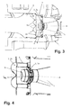
- the combustion chamber 3 is divided transversely to the central axis A by a partition member 5.
- a first sub-chamber 3a of the combustion chamber On the side of the cartridge bearing 4 there is a first sub-chamber 3a of the combustion chamber, and on the side of the piston 2 is a second sub-chamber 3b of the combustion chamber 3rd
- the separating member 5 is presently designed as a screwed by means of an external thread 7 in the combustion chamber 3 component.
- the isolator can also be formed integrally with the rest of the combustion chamber or be connected in any other way as a separate component with the combustion chamber.
- the partition member 5 has a plurality of apertures 6, which are in the present case designed as bores which extend parallel to the axis A.
- the perforations 6 are arranged around a central region 8 of the separating member 5, which has a closed and non-perforated surface.
- the smallest diameter of the central, unbroken portion 8 in a plane perpendicular to the axis A is about 35% larger than a diameter of the open after ignition cartridge. In the present case, this corresponds approximately to the diameter of a combustion chamber-side opening of the cartridge bearing or of a surface of the pyrotechnic charge directed into the combustion chamber.
- the fuel gases and powder grains, charge particles or the like ejected with them first enter the combustion chamber parallel to the central axis. Therefore, at least immediately after ignition and over a certain length, the expanding charge moves predominantly in a prismatic discharge region along the central axis, the circumference of which is defined by the contour of the surface of the charge.
- all of the apertures 6 of the partition member are located outside a sectional area of the ejection area with the surface of the partition member.
- the discharge area is designed as a cylinder corresponding to the circular cartridge opening.
- a recess 9 is further formed in the central region 8 of the separating member 5.
- the recess 9 extends rotationally symmetrical about the central axis A. It is formed cup-shaped and has a flat bottom 9a.
- a diameter of the recess 9 tapers from a largest diameter d at its upper edge to a smallest diameter at the level of the bottom 9a.
- the walls of the recess 9 have both inclined and straight sections.
- the maximum depth of the recess 9 is presently about 60% of the largest diameter d.
- the closed surface of the central region 8 extends to a step 10.
- the gradation 10 rises from the surface of the central region 8 in the axial direction to a roof of the combustion chamber 3.
- the separating member 5 is in the present case with the gradation 10 pressed against the roof. This is achieved by appropriate screwing of the separator 5 in the combustion chamber 3.
- the gradation 10 forms between adjacent apertures 6 each webs 11, which are directed radially inward. Accordingly, radially directed channels 12 remain between the webs 11, through which the fuel gases and charge particles initially flow radially outward from the central region 8 and are then deflected into the openings 6.
- the particles of the charge When passing through the openings 6, the particles of the charge are already predominantly burned, so that there are no larger unburned charge residues either in the openings or in the following, second partial chamber 3b. This prevents unfavorable deposits and / or clogging of the apertures 6. At the same time a controlled and uniform expansion of the fuel gases in the second sub-chamber is favored, so that an optimal acceleration of the piston 2 takes place.
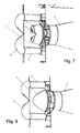
- the second embodiment of a separator a different shape of the recess 9 is provided.
- the recess is formed as a cup-shaped recess, but the walls of the recess are stronger and continuously inclined.
- a separating member is the shape of the recess 9 predominantly as in the example Fig. 6 .
- an upstanding, conical projection 13 is formed above the bottom of the recess.
- the recess 9 has no flat bottom, but has an overall approximately parabolic cross-section. Such a shape is particularly well suited for the prevention of deposits.
- a system for driving a fastener into a workpiece is provided by a tacker described above in conjunction with a propellant charge and a selection of fasteners.
- the system comprises a plurality of different attachment means, wherein only one type of propellant charge is required to cover a full range of drive-in energies.
- the driving energy transmitted to the piston member ranges from a minimum driving energy of 90 joules to a maximum driving energy of 325 joules.
Landscapes
- Engineering & Computer Science (AREA)
- Chemical & Material Sciences (AREA)
- Combustion & Propulsion (AREA)
- Mechanical Engineering (AREA)
- Portable Nailing Machines And Staplers (AREA)
Priority Applications (4)
| Application Number | Priority Date | Filing Date | Title |
|---|---|---|---|
| EP13198042.7A EP2886257A1 (fr) | 2013-12-18 | 2013-12-18 | Appareil d'enfoncement |
| EP14812510.7A EP3083152B1 (fr) | 2013-12-18 | 2014-12-16 | Appareil d'enfoncement |
| PCT/EP2014/077886 WO2015091431A1 (fr) | 2013-12-18 | 2014-12-16 | Appareil d'enfoncement |
| US15/104,345 US10556332B2 (en) | 2013-12-18 | 2014-12-16 | Driving device |
Applications Claiming Priority (1)
| Application Number | Priority Date | Filing Date | Title |
|---|---|---|---|
| EP13198042.7A EP2886257A1 (fr) | 2013-12-18 | 2013-12-18 | Appareil d'enfoncement |
Publications (1)
| Publication Number | Publication Date |
|---|---|
| EP2886257A1 true EP2886257A1 (fr) | 2015-06-24 |
Family
ID=49816872
Family Applications (2)
| Application Number | Title | Priority Date | Filing Date |
|---|---|---|---|
| EP13198042.7A Withdrawn EP2886257A1 (fr) | 2013-12-18 | 2013-12-18 | Appareil d'enfoncement |
| EP14812510.7A Active EP3083152B1 (fr) | 2013-12-18 | 2014-12-16 | Appareil d'enfoncement |
Family Applications After (1)
| Application Number | Title | Priority Date | Filing Date |
|---|---|---|---|
| EP14812510.7A Active EP3083152B1 (fr) | 2013-12-18 | 2014-12-16 | Appareil d'enfoncement |
Country Status (3)
| Country | Link |
|---|---|
| US (1) | US10556332B2 (fr) |
| EP (2) | EP2886257A1 (fr) |
| WO (1) | WO2015091431A1 (fr) |
Families Citing this family (5)
| Publication number | Priority date | Publication date | Assignee | Title |
|---|---|---|---|---|
| EP2886258A1 (fr) * | 2013-12-18 | 2015-06-24 | HILTI Aktiengesellschaft | Appareil d'enfoncement |
| EP2886260A1 (fr) * | 2013-12-19 | 2015-06-24 | HILTI Aktiengesellschaft | Appareil d'enfoncement |
| EP2923797A1 (fr) * | 2014-03-28 | 2015-09-30 | HILTI Aktiengesellschaft | Cloueur à poudre |
| EP2923800A1 (fr) * | 2014-03-28 | 2015-09-30 | HILTI Aktiengesellschaft | Cloueur à poudre |
| TWM526944U (zh) * | 2016-03-18 | 2016-08-11 | Chung-Yi Lee | 可調整擊釘力量的火藥擊釘器 |
Citations (5)
| Publication number | Priority date | Publication date | Assignee | Title |
|---|---|---|---|---|
| US5029744A (en) * | 1990-06-13 | 1991-07-09 | Hsin-Ho Mfg. Co. Ltd. | Mechanism for controlling the powder impact force on a projectile |
| EP0972615A2 (fr) * | 1998-07-13 | 2000-01-19 | HILTI Aktiengesellschaft | Outil de scellement actionné par poudre |
| US6321968B1 (en) | 1998-09-10 | 2001-11-27 | Senco Products, Inc. | Combustion chamber design for propellant charges and power adjustment means |
| DE10161355A1 (de) * | 2001-12-13 | 2003-06-26 | Hilti Ag | Setzgerät mit Energieregelung |
| US20100258609A1 (en) * | 2009-04-09 | 2010-10-14 | Lee Cheng-Ho | Powder-actuated fastener-driving device capable of power adjustment |
Family Cites Families (28)
| Publication number | Priority date | Publication date | Assignee | Title |
|---|---|---|---|---|
| US3786977A (en) * | 1972-05-23 | 1974-01-22 | Usm Corp | Explosive fastener driving tool |
| CH562665A5 (fr) * | 1972-08-07 | 1975-06-13 | Olin Authier Sa | |
| DE2420089A1 (de) * | 1974-04-25 | 1975-11-13 | Hilti Ag | Pulverkraftbetriebenes setzgeraet |
| DE2548014C2 (de) * | 1975-10-27 | 1984-01-12 | Hilti AG, 9494 Schaan | Pulverkraftbetriebenes Setzgerät mit Leistungsregulierung |
| DE2709065C2 (de) * | 1977-03-02 | 1986-02-20 | Hilti Ag, Schaan | Bolzensetzgerät |
| DE3016280A1 (de) * | 1980-04-28 | 1981-11-12 | Hilti AG, 9494 Schaan | Pulverkraftbetriebenes setzgeraet |
| DE3151658A1 (de) * | 1981-12-28 | 1983-07-07 | Hilti AG, 9494 Schaan | "setzgeraet mit von hochgespannten gasen verschieblichem treibkolben" |
| US4687126A (en) * | 1985-11-21 | 1987-08-18 | Research Plus, Inc. | Power actuated tool for driving fastener |
| FR2620368A1 (fr) | 1987-09-15 | 1989-03-17 | Prospection & Inventions | Appareil de scellement a tir indirect a puissance de tir variable |
| DE3806834A1 (de) * | 1988-03-03 | 1989-09-14 | Hilti Ag | Pulverkraftbetriebenes setzgeraet |
| PL172265B1 (pl) | 1994-03-02 | 1997-08-29 | Lagodzinska Boguslawa | Osadzak napedzany sila wybuchu ladunku prochowego z regulacja silyi glebokosci osadzania elementów mocujacych PL |
| DE19500320A1 (de) * | 1995-01-07 | 1996-07-11 | Hilti Ag | Pulverkraftbetriebenes Bolzensetzgerät |
| US5722578A (en) * | 1995-09-29 | 1998-03-03 | Illinois Tool Works Inc. | High velocity, combustion-powered, fastener-driving tool |
| AUPN585495A0 (en) * | 1995-10-09 | 1995-11-02 | Ramset Fasteners (Aust.) Pty. Limited | Power actuated tools with power adjustment means |
| DE19544104A1 (de) * | 1995-11-27 | 1997-05-28 | Hilti Ag | Pulverkraftbetriebenes Setzgerät |
| DE19547859A1 (de) * | 1995-12-21 | 1997-06-26 | Hilti Ag | Pulverkraftbetriebenes Setzgerät |
| US5799855A (en) * | 1996-02-09 | 1998-09-01 | Illinois Tool Works Inc. | Velocity control and nosepiece stabilizer system for combustion powered tools |
| DE19617671C1 (de) * | 1996-05-03 | 1997-10-09 | Beto Tornado Gmbh | Pulverkraftbetriebenes Bolzensetzgerät |
| US5699948A (en) * | 1996-12-16 | 1997-12-23 | Lee; Cheng-Ho | Adjusting means for use in a staple gun |
| DE50109817D1 (de) * | 2001-07-19 | 2006-06-22 | Hilti Ag | Bolzensetzgerät mit Setztiefenregelung |
| DE10161354B4 (de) | 2001-12-13 | 2013-11-21 | Hilti Aktiengesellschaft | Setzgerät mit Energieregelung |
| DE10259567A1 (de) * | 2002-12-19 | 2004-07-01 | Hilti Ag | Brennkraftbetriebenes Setzgerät |
| DE102005000032A1 (de) * | 2005-04-12 | 2006-10-19 | Hilti Ag | Brennkraftbetriebenes Setzgerät |
| US20100013137A1 (en) * | 2006-06-12 | 2010-01-21 | Hainbuch Gmbh Spannende Technik | Clamping Device |
| DE102010063173A1 (de) * | 2010-12-15 | 2012-06-21 | Hilti Aktiengesellschaft | Bolzensetzgerät und Verfahren zum Betreiben eines Bolzensetzgerätes |
| EP2886259A1 (fr) | 2013-12-18 | 2015-06-24 | HILTI Aktiengesellschaft | Appareil d'enfoncement |
| EP2886258A1 (fr) | 2013-12-18 | 2015-06-24 | HILTI Aktiengesellschaft | Appareil d'enfoncement |
| TWM526944U (zh) * | 2016-03-18 | 2016-08-11 | Chung-Yi Lee | 可調整擊釘力量的火藥擊釘器 |
-
2013
- 2013-12-18 EP EP13198042.7A patent/EP2886257A1/fr not_active Withdrawn
-
2014
- 2014-12-16 US US15/104,345 patent/US10556332B2/en active Active
- 2014-12-16 EP EP14812510.7A patent/EP3083152B1/fr active Active
- 2014-12-16 WO PCT/EP2014/077886 patent/WO2015091431A1/fr not_active Ceased
Patent Citations (5)
| Publication number | Priority date | Publication date | Assignee | Title |
|---|---|---|---|---|
| US5029744A (en) * | 1990-06-13 | 1991-07-09 | Hsin-Ho Mfg. Co. Ltd. | Mechanism for controlling the powder impact force on a projectile |
| EP0972615A2 (fr) * | 1998-07-13 | 2000-01-19 | HILTI Aktiengesellschaft | Outil de scellement actionné par poudre |
| US6321968B1 (en) | 1998-09-10 | 2001-11-27 | Senco Products, Inc. | Combustion chamber design for propellant charges and power adjustment means |
| DE10161355A1 (de) * | 2001-12-13 | 2003-06-26 | Hilti Ag | Setzgerät mit Energieregelung |
| US20100258609A1 (en) * | 2009-04-09 | 2010-10-14 | Lee Cheng-Ho | Powder-actuated fastener-driving device capable of power adjustment |
Also Published As
| Publication number | Publication date |
|---|---|
| WO2015091431A1 (fr) | 2015-06-25 |
| US20160311096A1 (en) | 2016-10-27 |
| US10556332B2 (en) | 2020-02-11 |
| EP3083152A1 (fr) | 2016-10-26 |
| EP3083152B1 (fr) | 2018-03-28 |
Similar Documents
| Publication | Publication Date | Title |
|---|---|---|
| EP3083152B1 (fr) | Appareil d'enfoncement | |
| EP3083154B1 (fr) | Appareil d'enfoncement | |
| DE69703042T2 (de) | Nichtletales geschoss | |
| EP3083151B1 (fr) | Appareil d'enfoncement | |
| EP3074186B1 (fr) | Cloueur à poudre | |
| EP3349944B1 (fr) | Appareil d'enfoncement entraîné par combustible doté d'une articulation de soupape | |
| DE112014002455B4 (de) | Pyrotechnischer Gasgenerator | |
| WO2015144687A1 (fr) | Dispositif d'enfoncement pyrotechnique | |
| EP1712334B1 (fr) | Appareil de scellement à combustion | |
| DE4447470A1 (de) | Infrarotköderpatrone | |
| EP3122516B1 (fr) | Cloueur à poudre | |
| EP4313492B1 (fr) | Appareil d'enfoncement pyrotechnique | |
| EP4313491B1 (fr) | Appareil d'enfoncement pyrotechnique | |
| DE10346031B4 (de) | Energie aufnehmende Vorrichtung, insbesondere für Lenksäulen | |
| DE102009037396B4 (de) | Pyrotechnisch betätigte Schneidvorrichtung | |
| DE602005006148T2 (de) | Pyrotechnisches betätigungsglied mit steuerbarer kraft und optimierter geometrie | |
| WO2018095783A1 (fr) | Corps actif pyrotechnique | |
| DE102010027577B4 (de) | Gefechtskopf | |
| DE102007050972A1 (de) | Gasbetriebener Lamellenmotor | |
| EP3457076B1 (fr) | Corps actif à couvercle de freinage | |
| WO2016096953A1 (fr) | Appareil d'enfoncement muni d'un passage dans une chambre de combustion | |
| WO2021032570A1 (fr) | Bande de cisaillement pour un dispositif de broyage de céréales en vrac | |
| EP3396301A1 (fr) | Grenade ainsi que procédé de fonctionnement d'une grenade |
Legal Events
| Date | Code | Title | Description |
|---|---|---|---|
| PUAI | Public reference made under article 153(3) epc to a published international application that has entered the european phase |
Free format text: ORIGINAL CODE: 0009012 |
|
| 17P | Request for examination filed |
Effective date: 20131218 |
|
| AK | Designated contracting states |
Kind code of ref document: A1 Designated state(s): AL AT BE BG CH CY CZ DE DK EE ES FI FR GB GR HR HU IE IS IT LI LT LU LV MC MK MT NL NO PL PT RO RS SE SI SK SM TR |
|
| AX | Request for extension of the european patent |
Extension state: BA ME |
|
| STAA | Information on the status of an ep patent application or granted ep patent |
Free format text: STATUS: THE APPLICATION IS DEEMED TO BE WITHDRAWN |
|
| 18D | Application deemed to be withdrawn |
Effective date: 20160105 |