EP2924287B1 - Compresseur à plateau oscillant à déplacement variable - Google Patents
Compresseur à plateau oscillant à déplacement variable Download PDFInfo
- Publication number
- EP2924287B1 EP2924287B1 EP15156858.1A EP15156858A EP2924287B1 EP 2924287 B1 EP2924287 B1 EP 2924287B1 EP 15156858 A EP15156858 A EP 15156858A EP 2924287 B1 EP2924287 B1 EP 2924287B1
- Authority
- EP
- European Patent Office
- Prior art keywords
- swash plate
- drive shaft
- acting portion
- chamber
- dead center
- Prior art date
- Legal status (The legal status is an assumption and is not a legal conclusion. Google has not performed a legal analysis and makes no representation as to the accuracy of the status listed.)
- Not-in-force
Links
- 238000006073 displacement reaction Methods 0.000 title claims description 11
- 230000007246 mechanism Effects 0.000 claims description 26
- 230000008859 change Effects 0.000 claims description 8
- 238000006243 chemical reaction Methods 0.000 claims description 6
- 230000033228 biological regulation Effects 0.000 description 17
- 230000003247 decreasing effect Effects 0.000 description 9
- 230000006835 compression Effects 0.000 description 8
- 238000007906 compression Methods 0.000 description 8
- 235000014676 Phragmites communis Nutrition 0.000 description 4
- 230000015572 biosynthetic process Effects 0.000 description 4
- 230000007423 decrease Effects 0.000 description 3
- 230000001105 regulatory effect Effects 0.000 description 3
- 238000004378 air conditioning Methods 0.000 description 2
- 230000005489 elastic deformation Effects 0.000 description 2
- 238000003780 insertion Methods 0.000 description 2
- 230000037431 insertion Effects 0.000 description 2
- 238000005057 refrigeration Methods 0.000 description 2
- 238000010586 diagram Methods 0.000 description 1
- 230000001747 exhibiting effect Effects 0.000 description 1
- 230000009467 reduction Effects 0.000 description 1
- 230000004044 response Effects 0.000 description 1
- 238000005096 rolling process Methods 0.000 description 1
Images



Classifications
-
- F—MECHANICAL ENGINEERING; LIGHTING; HEATING; WEAPONS; BLASTING
- F04—POSITIVE - DISPLACEMENT MACHINES FOR LIQUIDS; PUMPS FOR LIQUIDS OR ELASTIC FLUIDS
- F04B—POSITIVE-DISPLACEMENT MACHINES FOR LIQUIDS; PUMPS
- F04B27/00—Multi-cylinder pumps specially adapted for elastic fluids and characterised by number or arrangement of cylinders
- F04B27/08—Multi-cylinder pumps specially adapted for elastic fluids and characterised by number or arrangement of cylinders having cylinders coaxial with, or parallel or inclined to, main shaft axis
- F04B27/14—Control
- F04B27/16—Control of pumps with stationary cylinders
- F04B27/18—Control of pumps with stationary cylinders by varying the relative positions of a swash plate and a cylinder block
- F04B27/1804—Controlled by crankcase pressure
-
- F—MECHANICAL ENGINEERING; LIGHTING; HEATING; WEAPONS; BLASTING
- F04—POSITIVE - DISPLACEMENT MACHINES FOR LIQUIDS; PUMPS FOR LIQUIDS OR ELASTIC FLUIDS
- F04B—POSITIVE-DISPLACEMENT MACHINES FOR LIQUIDS; PUMPS
- F04B1/00—Multi-cylinder machines or pumps characterised by number or arrangement of cylinders
- F04B1/12—Multi-cylinder machines or pumps characterised by number or arrangement of cylinders having cylinder axes coaxial with, or parallel or inclined to, main shaft axis
- F04B1/14—Multi-cylinder machines or pumps characterised by number or arrangement of cylinders having cylinder axes coaxial with, or parallel or inclined to, main shaft axis having stationary cylinders
- F04B1/141—Details or component parts
- F04B1/146—Swash plates; Actuating elements
-
- F—MECHANICAL ENGINEERING; LIGHTING; HEATING; WEAPONS; BLASTING
- F04—POSITIVE - DISPLACEMENT MACHINES FOR LIQUIDS; PUMPS FOR LIQUIDS OR ELASTIC FLUIDS
- F04B—POSITIVE-DISPLACEMENT MACHINES FOR LIQUIDS; PUMPS
- F04B27/00—Multi-cylinder pumps specially adapted for elastic fluids and characterised by number or arrangement of cylinders
- F04B27/08—Multi-cylinder pumps specially adapted for elastic fluids and characterised by number or arrangement of cylinders having cylinders coaxial with, or parallel or inclined to, main shaft axis
- F04B27/10—Multi-cylinder pumps specially adapted for elastic fluids and characterised by number or arrangement of cylinders having cylinders coaxial with, or parallel or inclined to, main shaft axis having stationary cylinders
- F04B27/1036—Component parts, details, e.g. sealings, lubrication
- F04B27/1054—Actuating elements
- F04B27/1072—Pivot mechanisms
-
- F—MECHANICAL ENGINEERING; LIGHTING; HEATING; WEAPONS; BLASTING
- F04—POSITIVE - DISPLACEMENT MACHINES FOR LIQUIDS; PUMPS FOR LIQUIDS OR ELASTIC FLUIDS
- F04B—POSITIVE-DISPLACEMENT MACHINES FOR LIQUIDS; PUMPS
- F04B27/00—Multi-cylinder pumps specially adapted for elastic fluids and characterised by number or arrangement of cylinders
- F04B27/08—Multi-cylinder pumps specially adapted for elastic fluids and characterised by number or arrangement of cylinders having cylinders coaxial with, or parallel or inclined to, main shaft axis
- F04B27/14—Control
- F04B27/16—Control of pumps with stationary cylinders
- F04B27/18—Control of pumps with stationary cylinders by varying the relative positions of a swash plate and a cylinder block
- F04B27/1804—Controlled by crankcase pressure
- F04B2027/1822—Valve-controlled fluid connection
-
- F—MECHANICAL ENGINEERING; LIGHTING; HEATING; WEAPONS; BLASTING
- F04—POSITIVE - DISPLACEMENT MACHINES FOR LIQUIDS; PUMPS FOR LIQUIDS OR ELASTIC FLUIDS
- F04B—POSITIVE-DISPLACEMENT MACHINES FOR LIQUIDS; PUMPS
- F04B27/00—Multi-cylinder pumps specially adapted for elastic fluids and characterised by number or arrangement of cylinders
- F04B27/08—Multi-cylinder pumps specially adapted for elastic fluids and characterised by number or arrangement of cylinders having cylinders coaxial with, or parallel or inclined to, main shaft axis
- F04B27/14—Control
- F04B27/16—Control of pumps with stationary cylinders
- F04B27/18—Control of pumps with stationary cylinders by varying the relative positions of a swash plate and a cylinder block
- F04B27/1804—Controlled by crankcase pressure
- F04B2027/1822—Valve-controlled fluid connection
- F04B2027/1827—Valve-controlled fluid connection between crankcase and discharge chamber
-
- F—MECHANICAL ENGINEERING; LIGHTING; HEATING; WEAPONS; BLASTING
- F04—POSITIVE - DISPLACEMENT MACHINES FOR LIQUIDS; PUMPS FOR LIQUIDS OR ELASTIC FLUIDS
- F04B—POSITIVE-DISPLACEMENT MACHINES FOR LIQUIDS; PUMPS
- F04B27/00—Multi-cylinder pumps specially adapted for elastic fluids and characterised by number or arrangement of cylinders
- F04B27/08—Multi-cylinder pumps specially adapted for elastic fluids and characterised by number or arrangement of cylinders having cylinders coaxial with, or parallel or inclined to, main shaft axis
- F04B27/14—Control
- F04B27/16—Control of pumps with stationary cylinders
- F04B27/18—Control of pumps with stationary cylinders by varying the relative positions of a swash plate and a cylinder block
- F04B27/1804—Controlled by crankcase pressure
- F04B2027/1886—Open (not controlling) fluid passage
- F04B2027/1895—Open (not controlling) fluid passage between crankcase and suction chamber
Definitions
- the present invention relates to a variable displacement swash plate type compressor.
- Japanese Patent Laid-Open No. 52-131204 discloses a conventional variable displacement swash plate type compressor (hereinafter, described as a compressor).
- a compressor suction chambers, discharge chambers, a swash plate chamber, and a plurality of cylinder bores are formed in a housing.
- a drive shaft is rotatably supported in the housing.
- a swash plate chamber In the swash plate chamber, a swash plate that is rotatable by rotation of the drive shaft is provided.
- a link mechanism is provided between the drive shaft and the swash plate.
- the link mechanism allows change of an inclination angle of the swash plate.
- the inclination angle refers to an angle of the swash plate to the direction orthogonal to a drive shaft axis of the drive shaft.
- a conversion mechanism is constructed to cause the respective pistons to reciprocate in the cylinder bores at a stroke corresponding to the inclination angle by rotation of the swash plate. Further, an actuator changes the inclination angle.
- a control mechanism controls the actuator. The control mechanism has a pressure regulating valve.
- the link mechanism has a lug member, a hinge ball and a link.
- the lug member is fixed to the drive shaft in the swash plate chamber.
- the hinge ball is disposed in a center of the swash plate with the drive shaft being inserted therethrough.
- the hinge ball and the actuator are engaged with each other at the drive shaft axis side, that is, the center of the swash plate.
- the link is provided between the lug member and the swash plate.
- the swash plate is pivotably connected to the lug member via the link.
- the actuator has a lug member, a movable body, and a control pressure chamber.
- the movable body is inserted through the drive shaft, and moves in a drive shaft axis direction to be able to change the inclination angle.
- the control pressure chamber is defined by the lug member and the movable body, and moves the movable body by an internal pressure.
- the control mechanism allows the discharge chamber and the control pressure chamber to communicate with each other by the pressure regulating valve, and thereby the pressure in the control pressure chamber is increased.
- the movable body moves in the drive shaft axis direction to press the hinge ball. Therefore, in the compressor, the swash plate pivots on the hinge ball in a direction to decrease the inclination angle. In this manner, in the compressor, a discharge capacity per one rotation of the drive shaft can be decreased.
- a top dead center corresponding portion as a portion corresponding to a top dead center of the respective pistons and a bottom dead center corresponding portion as a portion corresponding to a bottom dead center of the respective pistons, and to cause the actuator and the swash plate to engage with each other in a position eccentric to the top dead center corresponding portion side in the swash plate from the center of the swash plate, in the compressor.
- the stroke in the drive shaft axis direction of the movable body can be made smaller than in the case in which the actuator and the swash plate are engaged with each other in the center of the swash plate. Thereby, reduction in the shaft of the compressor can be realized.
- a compression reaction force acts on the rotating swash plate at a posterior side in a rotating direction from the top dead center corresponding portion. Therefore, when the actuator presses the swash plate simply in the position eccentric to the top dead center corresponding portion side, a moment that inclines the swash plate in a direction with a line connecting the top dead center corresponding portion and the bottom dead center corresponding portion as a center of rotation acts on the swash plate. Therefore, hollowing occurs to the swash plate, and on changing the inclination angle, the actuator is difficult to move in the drive shaft axis direction. Therefore, in the compressor in this case, the inclination angle is difficult to change, and controllability is reduced.
- the present invention is made in the light of the above described conventional circumstances, and an object of the invention is to provide a variable displacement swash plate type compressor capable of exhibiting high controllability while realizing downsizing in a compressor that changes a discharge capacity by using an actuator.
- a variable displacement swash plate type compressor of the present invention comprises a housing in which a suction chamber, a discharge chamber, a swash plate chamber and a cylinder bore are formed, a drive shaft that is rotatably supported by the housing, a swash plate rotatable in the swash plate chamber by rotation of the drive shaft, a link mechanism that is provided between the drive shaft and the swash plate, and allows change of an inclination angle of the swash plate to a direction orthogonal to a drive shaft axis of the drive shaft, a piston that is accommodated in the cylinder bore to be capable of reciprocating, a conversion mechanism that causes the piston to reciprocate in the cylinder bore at a stroke corresponding to the inclination angle by rotation of the swash plate, an actuator capable of changing the inclination angle, and a control mechanism that controls the actuator, wherein the suction chamber and the swash plate chamber communicate with each other, the link mechanism has a lug member that is fixed to the drive shaft in the swash
- Compressors in Embodiments are variable displacement single head swash plate type compressors. This compressor is mounted on vehicles, and configures refrigeration circuits of vehicle air-conditioning apparatuses.
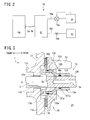
- a compressor of Embodiments includes a housing 1, a drive shaft 3, a swash plate 5, a link mechanism 7, pistons 9, a pair of shoes 11a and 11b, an actuator 13, and a control mechanism 15 shown in FIG. 2 .
- the housing 1 has a front housing 17 that is located at a front part of the compressor, a rear housing 19 that is located at a rear part of the compressor, a cylinder block 21 that is located between the front housing 17 and the rear housing 19, and a valve formation plate 23.
- the front housing 17 has a front wall 17a that extends in an up and down direction of the compressor in the front part, and a circumferential wall 17b that is integrated with the front wall 17a and extends toward the rear part from the front part of the compressor.
- the front housing 17 forms a substantially cylindrical shape with a bottom.
- a swash plate chamber 25 is formed in the front housing 17.
- a boss 17c that protrudes front is formed in the front wall 17a.
- a shaft seal device 27 is provided in the boss 17c.
- a first shaft hole 17d that extends in a longitudinal direction of the compressor is formed in the boss 17c.
- a first sliding bearing 29a is provided in the first shaft hole 17d.
- an inlet port 250 that communicates with the swash plate chamber 25 is formed.
- the swash plate chamber 25 is connected to an evaporator not illustrated.
- a pressure in the swash plate chamber 25 is lower than a pressure in a discharge chamber 35 that will be described later.
- a part of the control mechanism 15 is provided in the rear housing 19. Further, in the rear housing 19, a first pressure regulation chamber 31a, a suction chamber 33 and a discharge chamber 35 are formed.
- the first pressure regulation chamber 31a is located in a center portion of the rear housing 19.
- the discharge chamber 35 is located annularly at an outer circumferential side of the rear housing 19. Further, the suction chamber 33 is formed annularly between the first pressure regulation chamber 31a and the discharge chamber 35, in the rear housing 19.
- the discharge chamber 35 is connected to an outlet port not illustrated.
- cylinder bores 21a the number of which is the same as the number of the pistons 9 are formed in a circumferential direction at equiangular intervals. Front end sides of the respective cylinder bores 21a communicate with the swash plate chamber 25. Further, in the cylinder block 21, a retainer groove 21b that regulates a maximum angle of a suction reed valve 41a that will be described later is formed.
- a second shaft hole 21c that extends in the longitudinal direction of the compressor while communicating with the swash plate chamber 25 is provided to penetrate the cylinder block 21.
- a second sliding bearing 29b is provided in the second shaft hole 21c. Note that in place of the first sliding bearing 29a and the second sliding bearing 29b described above, rolling bearings can be adopted respectively.
- a spring chamber 21d is formed.
- the spring chamber 21d is located between the swash plate chamber 25 and the second shaft hole 21c.
- a return spring 37 is disposed in the spring chamber 21d.
- the return spring 37 urges the swash plate 5 the inclination angle of which is minimum toward a front part of the swash plate chamber 25.
- a suction passage 39 that communicates with the swash plate chamber 25 is formed.
- the valve formation plate 23 is provided between the rear housing 19 and the cylinder block 21.
- the valve formation plate 23 consists of a valve plate 40, a suction valve plate 41, a discharge valve plate 43 and a retainer plate 45.
- suction ports 40a the number of which is the same as the number of the cylinder bores 21a are formed.
- discharge ports 40b the number of which is the same as the number of the cylinder bores 21a are formed.
- the respective cylinder bores 21a communicate with the suction chamber 33 through the respective suction ports 40a, and communicate with the discharge chamber 35 through the respective discharge ports 40b.
- a first communication hole 40c and a second communication hole 40d are formed.
- the suction valve plate 41 is provided on a front surface of the valve plate 40. At the suction valve plate 41, a plurality of suction reed valves 41a capable of opening and closing the respective suction ports 40a by elastic deformation are formed. Further, the discharge valve plate 43 is provided on a rear surface of the valve plate 40. At the discharge valve plate 43, a plurality of discharge reed valves 43a capable of opening and closing the respective discharge ports 40b by elastic deformation are formed.
- the retainer plate 45 is provided on a rear surface of the discharge valve plate 43. The retainer plate 45 restricts a maximum opening degree of the discharge reed valve 43a.
- the drive shaft 3 is inserted toward a rear side of the housing 1 from a boss 17c side.
- a front end side of the drive shaft 3 is inserted through the shaft seal device 27 in the boss 17c, and supported by the first sliding bearing 29a in the first shaft hole 17d.
- a rear end side of the drive shaft 3 is supported by the second sliding bearing 29b in the second shaft hole 21c.
- the drive shaft 3 is supported rotatably around a drive shaft axis O with respect to the housing 1.
- a second pressure regulation chamber 31b is defined in a space from a rear end of the drive shaft 3.
- the second pressure regulation chamber 31b communicates with the first pressure regulation chamber 31a through the second communication hole 40d.
- O-rings 49a and 49d are provided at the rear end of the drive shaft 3. Thereby, the respective O-rings 49a and 49b are located between the drive shaft 3 and the second shaft hole 21c to seal a space between the swash plate chamber 25 and the pressure regulation chamber 31.
- the link mechanism 7 consists of a lug plate 51, a pair of lug arms 53 that are formed at the lug plate 51, and a pair of swash plate arm 5e that is formed at the swash plate 5.
- the lug plate 51 corresponds to a lug member in the present invention. Note that in FIG. 1 , with respect to the lug arms 53 and the swash plate arms 5e, only one of the lug arms 53 and one of the swash plate arms 5e are illustrated. The same also applies to FIG. 6 .
- the lug plate 51 is formed into a substantially annular ring shape.
- the lug plate 51 is press-fitted into the drive shaft 3, and is rotatable integrally with the drive shaft 3.
- the lug plate 51 is located at a front end side in the swash plate chamber 25, is disposed front of the swash plate 5 and faces the swash plate 5. Further, between the lug plate 51 and the front wall 17a, a thrust bearing 55 is provided.
- a cylindrical cylinder chamber 51a that extends in a longitudinal direction of the lug plate 51 is concavely provided.
- the cylinder chamber 51a extends to a spot to be an inner side of the thrust bearing 55 in the lug plate 51, from the rear end surface of the lug plate 51.
- the respective lug arms 53 extend rearward from the lug plate 51. Further, on the lug plate 51, a guide surface 51b is formed at a position between the respective lug arms 53. Though not illustrated, a pair of guide surfaces 51b are formed respectively to correspond to the respective lug arms 53. The guide surfaces 51b are formed with a downward inclination to a rear end side from a front end side of the lug plate 51.
- the swash plate 5 forms an annular flat plate shape, and has a front surface 5a and a rear surface 5b. On the front surface 5a, a weight portion 5c that protrudes front of the swash plate 5 is formed. The weight portion 5c abuts on the lug plate 51 when the inclination angle of the swash plate 5 becomes maximum. Further, as shown in FIG. 4 , an insertion hole 5d is formed in the swash plate 5. The drive shaft 3 is inserted through the insertion hole 5d. Note that in order to facilitate explanation, illustration of the respective swash plate arms 5e, the weight portion 5c, and the like is omitted in FIG. 4 .
- an affected portion 5f is formed on the front surface 5a.
- the affected portion 5f is formed to be flat.
- a top dead center corresponding portion T is defined as a portion corresponding to a top dead center of the respective pistons 9.
- the affected portion 5f is located eccentrically to the top dead center corresponding portion T side in the swash plate 5 from the drive shaft axis O, in the front surface 5a.
- the respective swash plate arms 5e are formed on the front surface 5a.
- the respective swash plate arms 5e extend front from the front surface 5a.
- the respective swash plate arms 5e are inserted between the respective lug arms 53, whereby the lug plate 51 and the swash plate 5 are connected. Thereby, rotation of the drive shaft 3 is transmitted to the respective swash plate arms 5e from the respective lug arms 53, and the swash plate 5 is rotatable with the lug plate 51, in the swash plate chamber 25.
- the lug plate 51 and the swash plate 5 are connected, whereby in the respective swash plate arms 5e, respective tip end sides abut on the guide surfaces 51b. Subsequently, the respective swash plate arms 5e slide on the guide surfaces 51b, whereby the swash plate 5 is pivotable around a pivoting axis M shown in FIG.
- the swash plate 5 can change to a minimum inclination angle shown in FIG. 6 from a maximum inclination angle shown in FIG. 1 .
- the actuator 13 consists of the lug plate 51, a movable body 13a and a control pressure chamber 13b.
- the movable body 13a is inserted through the drive shaft 3, and is movable in a longitudinal direction inside the swash plate chamber 25 in the drive shaft axis O direction while sliding in contact with the drive shaft 3.
- the movable body 13a forms a cylindrical shape coaxial with the drive shaft 3.
- the movable body 13a has a first cylinder portion 131, a second cylinder portion 132 and a connection portion 133.
- the first cylinder portion 131 is located at a rear part of the movable body 13a, namely, a side near to the swash plate 5, and is slidable in contact with the drive shaft 3 on an inner circumferential surface.
- a ring groove 131a is formed, and an O-ring 49c is provided in the ring groove 131a.
- the second cylinder portion 132 is located at a front part of the movable body 13a.
- the second cylinder portion 132 is formed to have a larger diameter than the first movable body 131.
- a ring groove 132a is formed, and an O-ring 49d is provided in the ring groove 132a.
- connection portion 133 is located between the first cylinder portion 131 and the second cylinder portion 132, and extends while gradually enlarging a diameter toward the front part from a rear part of the movable body 13a. In the connection portion 133, a rear end continues to the first cylinder portion 131, and a front end continues to the second cylinder portion 132.
- a first acting portion 134 and a second acting portion 135 are formed at a rear end of the first cylinder portion 131.
- the first and the second acting portions 134 and 135 extend toward the rear part of the movable body 13a from an outer circumferential surface of the first cylinder portion 131.
- first and the second acting portions 134 and 135 are formed on the first cylinder portion 131 in such a manner as to step across a top dead center surface F that is formed by the top dead center corresponding portion T of the swash plate 5 and the drive shaft axis O, as shown in FIG. 5B .
- the movable body 13a has the drive shaft 3 inserted therethrough, whereby the drive shaft 3 is located between the first acting portion 134 and the second acting portion 135.
- first acting portion 134 and the second acting portion 135 are formed to be plane-symmetrical with respect to the top dead center surface F. Thereby, a distance L1 from the first acting portion 134 to the top dead center surface F, and a distance L2 from the second acting portion 135 to the top dead center surface F have equal lengths. Further, the first acting portion 134 and the second acting portion 135 are formed on the first cylinder portion 131 so that heights from the drive shaft axis O are equal.
- the first acting portion 134 and the second acting portion 135 are both provided to be located inside the second cylinder portion 132.
- the first acting portion 134 and the second acting portion 135 are provided at positions that are outside from the first cylinder portion 131 and are inside the second cylinder portion 132.
- first acting portion 134 and the second acting portion 135 are located to be eccentric to the top dead center corresponding portion T side from the drive shaft axis O.
- rear ends of the first and the second acting portions 134 and 135 are formed into cylindrical shapes that protrude toward the swash plate 5 side. More specifically, the rear ends of the first and the second acting portions 134 and 135 are formed into cylindrical shapes having generating lines parallel with the pivoting axis M.
- the pivoting axis M includes a pivoting point X that is located on an intersection line of the outer circumferential surface of the drive shaft 3 and the top dead center surface F, and extends in a direction orthogonal to the drive shaft axis O.
- the first and the second acting portions 134 and 135 are respectively in linear contact with the affected surface 5f of the swash plate 5 in parallel with the pivoting axis M. That is to say, the first and the second acting portions 134 and 135 and the affected surface 5f are in linear contact with one another in positions eccentric to the top dead center corresponding portion T side from the drive shaft axis O (see FIG. 5A ). The first and the second acting portions 134 and 135 are in linear contact with the affected surface 5f like this, whereby the movable body 13a is rotatable integrally with the lug plate 51 and the swash plate 5.
- the cylinder chamber 51a can accommodate the second cylinder portion 132 and the connection portion 133 by causing the second cylinder portion 132 and the connection portion 133 to advance to an inside.
- the control pressure chamber 13b is formed among the second cylinder portion 132, the connection portion 133, the cylinder chamber 51a and the drive shaft 3. A space between the control pressure chamber 13b and the swash plate chamber 25 is sealed by the O-rings 49c and 49d.
- an axial path 3a that extends in the drive shaft axis O direction toward the front end from the rear end of the drive shaft 3, and a radial path 3b that extends in a radial direction from a front end of the axial path 3a and opens to the outer circumferential surface of the drive shaft 3 are formed.
- a rear end of the axial path 3a opens to the pressure regulation chamber 31.
- the radial path 3b opens to the control pressure chamber 13b.
- a screw portion 3c is formed on a tip end of the drive shaft 3.
- the drive shaft 3 is connected to a pulley or an electromagnetic clutch not illustrated, through the screw portion 3c.
- the respective pistons 9 are respectively accommodated in the respective cylinder bores 21a, and are capable of reciprocating in the respective cylinder bores 21a.
- compression chambers 57 are defined in the respective cylinder bores 21a.
- engaging portions 9a are concavely provided respectively.
- the semispherical shoes 11a and 11b are respectively provided.
- the respective shoes 11a and 11b convert rotation of the swash plate 5 into reciprocal movement of the respective pistons 9.
- the respective shoes 11a and 11b correspond to a conversion mechanism in the present invention. In this manner, the respective pistons 9 can reciprocate in the cylinder bores 21a respectively at a stroke corresponding to the inclination angle of the swash plate 5.
- control mechanism 15 is configured by a low-pressure passage 15a, a high-pressure passage 15b, a control valve 15c, an orifice 15d, the axial path 3a and the radial path 3b.
- the low-pressure passage 15a is connected to the pressure regulation chamber 31 and the suction chamber 33. Thereby, by the low-pressure passage 15a, the axial path 3a and the radial path 3b, the control pressure chamber 13b, the pressure regulation chamber 31 and the suction chamber 33 are brought into a state communicating to one another.
- the high-pressure passage 15b is connected to the pressure regulation chamber 31 and the discharge chamber 35. By the high-pressure passage 15b, the axial path 3a and the radial path 3b, the control pressure chamber 13b, the pressure regulation chamber 31 and the discharge chamber 35 communicate with one another.
- the control valve 15c is provided in the low-pressure passage 15a.
- the low-pressure control valve 15c can regulate an opening degree of the low-pressure passage 15a based on a pressure in the suction chamber 33.
- the orifice 15d is provided in the high-pressure passage 15b.
- piping connecting to the evaporator is connected to the inlet port 250 shown in FIG. 1
- piping connecting to a condenser is connected to the outlet port.
- the condenser is connected to the evaporator via piping and an expansion valve.
- the drive shaft 3 rotates, whereby the swash plate 5 rotates, and the respective pistons 9 reciprocate in the respective cylinder bores 21a. Therefore, the compression chamber 57 changes a capacity in response to a piston stroke. Therefore, the refrigerating gas which is sucked into the swash plate chamber 25 by the inlet port 250 from the evaporator passes through the suction chamber 33 from the suction passage 39 and is compressed in the compression chamber 57. Subsequently, the refrigerating gas which is compressed in the compression chamber 57 is discharged into the discharge chamber 35 and is discharged into the condenser from the outlet port.
- the inclination angle of the swash plate 5 is changed to increase or decrease the stroke of the respective pistons 9 by an actuator 13, and thereby discharge capacity can be changed.
- the swash plate arm 5e slides on the sliding surface 51b respectively so as to be away from the drive shaft axis O.
- a bottom dead center corresponding portion U is defined as a portion corresponding to a bottom dead center of the respective pistons 9.
- the bottom dead center corresponding portion U side in the swash plate 5 pivots in a clockwise direction around the pivoting axis M while the position of the top dead center corresponding portion T is substantially kept in the swash plate 5.
- the inclination angle of the swash plate 5 to the drive shaft axis O of the drive shaft 3 increases.
- the stroke of the respective pistons 9 increases, and the discharge capacity per one rotation of the drive shaft 3 becomes large.
- the inclination angle of the swash plate 5 shown in FIG. 1 is a maximum inclination angle in the compressor.
- the first acting portion 134 and the second acting portion 135 respectively press the swash plate 5 toward the rear part of the swash plate chamber 25, in the compressor. Therefore, as shown in FIG. 6 , the respective swash plate arms 5e respectively slide on the respective sliding surfaces 51b so as to be close to the drive shaft axis O.
- the bottom dead center corresponding portion U side pivots in a counterclockwise direction around the pivoting axis M while the swash plate 5 substantially keeps the position of the top dead center corresponding portion T.
- the inclination angle of the swash plate 5 relative to the drive shaft axis O of the drive shaft 3 is decreased.
- the stroke of the respective pistons 9 decreases, and the discharge capacity per one rotation of the drive shaft 3 becomes small.
- the swash plate 5 abuts on the return spring 37 by the inclination angle decreasing. Note that the inclination angle of the swash plate 5 shown in FIG. 6 is the minimum inclination angle in the compressor.
- the first acting portion 134, the second acting portion 135 and the affected portion 5f are in linear contact in the position eccentric to the top dead center corresponding portion T side of the front surface 5a of the swash plate 5 from the drive shaft axis O.
- the first acting portion 134 and the second acting portion 135 press the affected portion 5f, whereby the inclination angle of the swash plate 5 can be decreased. Therefore, in the compressor, the stroke in the drive shaft direction O of the movable body 13a can be made small at a time of changing the inclination angle of the swash plate 5.
- a compression reaction force acts on the swash plate 5 at the posterior side in the rotation direction from the top dead center corresponding portion T, when the compressor is operated as described above.
- a moment M (see the broken line arrow in FIG. 4 ) that inclines the swash plate 5 in a direction with a line Y (see FIG. 5B ) that connects the top dead center corresponding portion T and the bottom dead center corresponding portion U as a center of rotation acts on the swash plate 5.
- the first acting portion 134 and the second acting portion 135 are paired in such a manner as to step across the top dead center surface F in the compressor. Therefore, in the compressor, at the time of decreasing the inclination angle, the first acting portion 134 and the second acting portion 135 separately press the affected portion 5f with the top dead center surface F as the reference. Thereby, in the compressor, the inclination of the swash plate 5 with the line Y connecting the top dead center corresponding portion T and the bottom dead center corresponding portion U as the center of rotation can be supported by the first acting portion 134 and the second acting portion 135.
- the first acting portion 134 and the second acting portion 135 are formed on the first cylinder portion 131 to be plane-symmetrical with respect to the top dead center surface F. Therefore, in the compressor, the first acting portion 134 and the second acting portion 135 can support the inclination of the swash plate 5 in the positions which are equal distance from the top dead center surface F.
- the movable body 13a easily moves favorably in the drive shaft axis O direction toward the swash plate 5 side while moving away from the lug plate 51, on decreasing the inclination angle. Thereby, in the compressor, the inclination angle is easily changed.
- the compressor of the embodiment exhibits high controllability while realizing downsizing, in the compressor which changes the discharge capacity by using the actuator 13.
- the drive shaft 3 is located between the first acting portion 134 and the second acting portion 135 as described above. More specifically, the first acting portion 134 and the second acting portion 135 are provided in the positions which are outside from the first cylinder portion 131, and inside of the second cylinder portion 132. Thereby, in the compressor, the space between the first acting portion 134 and the second acting portion 135 can be made as large as possible while increase in size of the movable body 13a is restrained. Thereby, the inclination of the swash plate 5 as described above can be favorably supported by the first acting portion 134 and the second acting portion 135 while increase in size of the movable body 13a, increase in size of the compressor by extension is restrained.
- the respective rear end sides of the first acting portion 134 and the second acting portion 135 are formed into the cylindrical shapes having the generating lines parallel with the pivoting axis M. Therefore, in the compressor, the first acting portion 134 and the second acting portion 135 are respectively in linear contact with the affected portion 5f. Thereby, in the compressor, contact pressure at the time of the first acting portion 134 and the second acting portion 135 pressing the swash plate 5 is reduced, and durability of the movable body 13a and the swash plate 5 is high.
- first acting portion 134 and the second acting portion 135 may be formed on the first cylinder portion 131 so that heights from the drive shaft axis O differ in the first acting portion 134 and the second acting portion 135 while the distance L1 from the first acting portion 134 to the top dead center surface F, and the distance L2 from the second acting portion 135 to the top dead center surface F are kept equal to each other.
- the affected portion 5f may be formed into a shape that protrudes toward the first and the second acting portions 134 and 135 from the front surface 5a of the swash plate 5.
- control mechanism 15 may have a structure in which the control valve 15c is provided in the high-pressure passage 15b, and the orifice 15d is provided in the low-pressure passage 15a.
- an opening degree of the high-pressure passage 15b is regulated by the control valve 15c, whereby the pressure of the control pressure chamber 13b can be quickly made high by the high pressure in the discharge chamber 35, and the discharge capacity can be quickly decreased.
- a first acting portion 134 and a second acting portion 135 are formed at a rear end of a firsf cylinder portion 131 of a movable body 13a.
- the first and the second acting portions 134 and 135 are formed by stepping across a top dead center surface F, and are plane-symmetrical with respect to the top dead center surface F.
- an affected portion 5f is formed on a front surface 5a of a swash plate 5.
- the first and the second acting portions 134 and 135 and the affected portion 5f are located eccentrically to a top dead center position corresponding portion T side from a drive shaft axis O.
- the first acting portion 134 and the second acting portion 135 separately press the affected portion 5f with the top dead center surface F as a reference.
- the movable body 13a favorably moves in a drive shaft axis O direction.
Landscapes
- Engineering & Computer Science (AREA)
- Mechanical Engineering (AREA)
- General Engineering & Computer Science (AREA)
- Compressors, Vaccum Pumps And Other Relevant Systems (AREA)
- Manufacturing & Machinery (AREA)
Claims (5)
- Compresseur à cylindrée variable de type à plateau oscillant comprenant :un boîtier (1) dans lequel sont formés une chambre d'aspiration (35), une chambre de décharge (35), une chambre de plateau oscillant (25) et un alésage de cylindre (21a) ;un arbre d'entraînement (3) qui est supporté de manière rotative par le boîtier (1) ;un plateau oscillant (5) pouvant tourner dans la chambre de plateau oscillant (25) par la rotation de l'arbre d'entraînement (3) ;un mécanisme de liaison (7) qui est prévu entre l'arbre d'entraînement (3) et le plateau oscillant (5) et permet le changement d'un angle d'inclinaison du plateau oscillant (5) dans une direction orthogonale à un axe d'arbre d'entraînement (0) de l'arbre d'entraînement (3) ;un piston (9) qui est logé dans l'alésage de cylindre (21a) pour pouvoir effectuer un mouvement de va-et-vient ;un mécanisme de conversion (lla, 11b) qui amène le piston (9) à effectuer un mouvement de va-et-vient dans l'alésage de cylindre (21a) à une course correspondant à l'angle d'inclinaison, par la rotation du plateau oscillant (5) ;un actionneur (13) pouvant changer l'angle d'inclinaison, etun mécanisme de commande (15) qui commande l'actionneur (13),dans lequel la chambre d'aspiration (33) et la chambre de plateau oscillant (25) communiquent entre elles,le mécanisme de liaison (7) a un élément de patte (51) qui est fixé sur l'arbre d'entraînement (3) dans la chambre de plateau oscillant (25) et fait face au plateau oscillant (5) et un bras de plateau oscillant (5e) dans lequel la rotation de l'arbre d'entraînement (3) est transmise au plateau oscillant (5) à partir de l'élément de patte (51),l'actionneur (13) a l'élément de patte (51), un corps mobile (13a) qui est disposé entre l'élément de patte (51) et le plateau oscillant (5) pour se mettre en prise avec le plateau oscillant (5) pour pouvoir tourner conjointement avec ce dernier et se déplace dans une direction de l'axe d'arbre d'entraînement (0) pour pouvoir changer l'angle d'inclinaison et une chambre de pression de commande (13b) qui est définie par l'élément de patte (51) et le corps mobile (13a), et déplace le corps mobile (13a) par une pression interne,caractérisé en ce quesur le corps mobile (13a), sont formées une première partie d'actionnement (134) et une seconde partie d'actionnement (135) qui se mettent en prise avec le plateau oscillant (5),sur le plateau oscillant (5), est formée une partie affectée (5f) qui se met en prise avec la première partie d'actionnement (134) et la seconde partie d'actionnement (135),dans le plateau oscillant (5), une partie correspondant au point mort haut (T) est définie comme étant une partie correspondant à un point mort haut du piston (9),la première partie d'actionnement (134), la seconde partie d'actionnement (135) et la partie affectée (5f) sont positionnées de manière excentrique du côté de la partie correspondant au point mort haut (T) dans le plateau oscillant (5) à partir de l'axe d'arbre d'entraînement (0), etla première partie d'actionnement (134) et la seconde partie d'actionnement (135) sont mises en paire en traversant une surface de point mort haut (F) qui est formée par la partie correspondant au point mort haut (T) et l'axe d'arbre d'entraînement (0).
- Compresseur à cylindrée variable de type à plateau oscillant selon la revendication 1,
dans lequel une distance allant de la première partie d'actionnement (134) à la surface de point mort haut (F) et une distance allant de la seconde partie d'actionnement (135) à la surface de point mort haut (F) sont sensiblement égales entre elles. - Compresseur à cylindrée variable de type à plateau oscillant selon la revendication 2,
dans lequel la première partie d'actionnement (134) et la seconde partie d'actionnement (135) sont symétriques en plan par rapport à la surface de point mort haut (F). - Compresseur à cylindrée variable de type à plateau oscillant selon la revendication 3,
dans lequel l'arbre d'entraînement (3) est présent entre la première partie d'actionnement (134) et la seconde partie d'actionnement (135). - Compresseur à cylindrée variable de type à plateau oscillant selon l'une quelconque des revendications 1 à 4,
dans lequel le plateau oscillant (5) est prévu de manière pivotante autour d'un axe de pivotement (M) comprenant un point de pivotement (X) qui est positionné sur une ligne d'intersection d'une surface circonférentielle externe de l'arbre d'entraînement (3) et la surface de point mort haut (F), et
la première partie d'actionnement (134) et la seconde partie d'actionnement (135) sont formées en formes cylindriques ayant des lignes génératrices parallèles à l'axe de pivotement (M).
Applications Claiming Priority (1)
| Application Number | Priority Date | Filing Date | Title |
|---|---|---|---|
| JP2014059599A JP6194830B2 (ja) | 2014-03-24 | 2014-03-24 | 容量可変型斜板式圧縮機 |
Publications (2)
| Publication Number | Publication Date |
|---|---|
| EP2924287A1 EP2924287A1 (fr) | 2015-09-30 |
| EP2924287B1 true EP2924287B1 (fr) | 2016-10-26 |
Family
ID=52577771
Family Applications (1)
| Application Number | Title | Priority Date | Filing Date |
|---|---|---|---|
| EP15156858.1A Not-in-force EP2924287B1 (fr) | 2014-03-24 | 2015-02-27 | Compresseur à plateau oscillant à déplacement variable |
Country Status (5)
| Country | Link |
|---|---|
| US (1) | US9784259B2 (fr) |
| EP (1) | EP2924287B1 (fr) |
| JP (1) | JP6194830B2 (fr) |
| KR (1) | KR101710930B1 (fr) |
| CN (1) | CN104948420B (fr) |
Families Citing this family (4)
| Publication number | Priority date | Publication date | Assignee | Title |
|---|---|---|---|---|
| JP6146263B2 (ja) * | 2013-11-06 | 2017-06-14 | 株式会社豊田自動織機 | 容量可変型斜板式圧縮機 |
| TWI566616B (zh) * | 2015-03-04 | 2017-01-11 | 瑞昱半導體股份有限公司 | 三方交握方法以及電腦可讀媒體 |
| KR20220162238A (ko) | 2021-05-31 | 2022-12-08 | 현대모비스 주식회사 | 차량의 운전 지원 방법 및 장치 |
| JP2023151481A (ja) * | 2022-03-31 | 2023-10-16 | 川崎重工業株式会社 | 回転斜板式液圧ポンプ |
Family Cites Families (19)
| Publication number | Priority date | Publication date | Assignee | Title |
|---|---|---|---|---|
| US4037993A (en) * | 1976-04-23 | 1977-07-26 | Borg-Warner Corporation | Control system for variable displacement compressor |
| US4061443A (en) * | 1976-12-02 | 1977-12-06 | General Motors Corporation | Variable stroke compressor |
| US4174191A (en) * | 1978-01-18 | 1979-11-13 | Borg-Warner Corporation | Variable capacity compressor |
| JPS62225782A (ja) * | 1986-03-27 | 1987-10-03 | Nippon Denso Co Ltd | 可変容量型揺動板式圧縮機 |
| JP2949836B2 (ja) * | 1990-11-26 | 1999-09-20 | 株式会社豊田自動織機製作所 | 斜板式連続可変容量型圧縮機 |
| JPH0518355A (ja) * | 1991-07-15 | 1993-01-26 | Toyota Autom Loom Works Ltd | 可変容量型圧縮機 |
| JPH05172052A (ja) | 1991-12-18 | 1993-07-09 | Sanden Corp | 可変容量斜板式圧縮機 |
| JP2917767B2 (ja) * | 1993-09-24 | 1999-07-12 | 株式会社豊田自動織機製作所 | 容量可変型斜板式圧縮機 |
| JPH08105384A (ja) * | 1994-10-05 | 1996-04-23 | Sanden Corp | 可変容量斜板式圧縮機 |
| TW400919U (en) * | 1996-03-12 | 2000-08-01 | Toyoda Automatic Loom Works | Variable volume capacity typed compressor |
| JPH10153171A (ja) * | 1996-11-22 | 1998-06-09 | Toyota Autom Loom Works Ltd | 両頭ピストン式可変容量型圧縮機 |
| DE19939131A1 (de) * | 1999-08-18 | 2001-03-08 | Zexel Gmbh | Axialkolbentriebwerk mit einem stufenlos verstellbaren Kolbenhub |
| KR100318772B1 (ko) * | 1999-12-16 | 2001-12-28 | 신영주 | 가변용량 사판식 압축기 |
| JP2001304102A (ja) * | 2000-04-18 | 2001-10-31 | Toyota Industries Corp | 可変容量圧縮機 |
| JP2004211570A (ja) * | 2002-12-27 | 2004-07-29 | Zexel Valeo Climate Control Corp | 可変容量型圧縮機 |
| KR20060085002A (ko) * | 2005-01-21 | 2006-07-26 | 학교법인 두원학원 | 피스톤의 자전방지구조, 및 이를 포함하는 용량 가변형사판식 압축기 |
| JP6047307B2 (ja) * | 2012-05-28 | 2016-12-21 | サンデンホールディングス株式会社 | 可変容量圧縮機 |
| JP6136906B2 (ja) * | 2013-12-11 | 2017-05-31 | 株式会社豊田自動織機 | 容量可変型斜板式圧縮機 |
| JP6217474B2 (ja) * | 2014-03-14 | 2017-10-25 | 株式会社豊田自動織機 | 容量可変型斜板式圧縮機 |
-
2014
- 2014-03-24 JP JP2014059599A patent/JP6194830B2/ja not_active Expired - Fee Related
-
2015
- 2015-02-27 EP EP15156858.1A patent/EP2924287B1/fr not_active Not-in-force
- 2015-03-12 US US14/656,100 patent/US9784259B2/en not_active Expired - Fee Related
- 2015-03-23 CN CN201510128701.8A patent/CN104948420B/zh not_active Expired - Fee Related
- 2015-03-23 KR KR1020150040103A patent/KR101710930B1/ko not_active Expired - Fee Related
Also Published As
| Publication number | Publication date |
|---|---|
| JP6194830B2 (ja) | 2017-09-13 |
| EP2924287A1 (fr) | 2015-09-30 |
| US9784259B2 (en) | 2017-10-10 |
| CN104948420B (zh) | 2017-05-24 |
| JP2015183563A (ja) | 2015-10-22 |
| KR101710930B1 (ko) | 2017-02-28 |
| CN104948420A (zh) | 2015-09-30 |
| US20150267692A1 (en) | 2015-09-24 |
| KR20150110417A (ko) | 2015-10-02 |
Similar Documents
| Publication | Publication Date | Title |
|---|---|---|
| KR101659812B1 (ko) | 용량 가변형 사판식 압축기 | |
| EP2924287A1 (fr) | Compresseur à plateau oscillant à déplacement variable | |
| KR101603439B1 (ko) | 용량 가변형 사판식 압축기 | |
| US20150260175A1 (en) | Variable displacement swash plate type compressor | |
| KR101796406B1 (ko) | 용량 가변형 사판식 압축기 | |
| US20160153435A1 (en) | Variable displacement swash-plate compressor | |
| KR101710929B1 (ko) | 용량 가변형 사판식 압축기 | |
| CN105889017B (zh) | 可变排量旋转斜板式压缩机 | |
| US9915252B2 (en) | Variable displacement swash plate compressor having a fulcrum and an action point located on opposite sides of a drive shaft | |
| US9651034B2 (en) | Variable displacement swash-plate compressor | |
| US9903353B2 (en) | Variable displacement swash plate compressor | |
| US9790936B2 (en) | Variable displacement swash plate compressor | |
| JP2016102418A (ja) | 容量可変型斜板式圧縮機 |
Legal Events
| Date | Code | Title | Description |
|---|---|---|---|
| PUAI | Public reference made under article 153(3) epc to a published international application that has entered the european phase |
Free format text: ORIGINAL CODE: 0009012 |
|
| 17P | Request for examination filed |
Effective date: 20150227 |
|
| AK | Designated contracting states |
Kind code of ref document: A1 Designated state(s): AL AT BE BG CH CY CZ DE DK EE ES FI FR GB GR HR HU IE IS IT LI LT LU LV MC MK MT NL NO PL PT RO RS SE SI SK SM TR |
|
| AX | Request for extension of the european patent |
Extension state: BA ME |
|
| GRAP | Despatch of communication of intention to grant a patent |
Free format text: ORIGINAL CODE: EPIDOSNIGR1 |
|
| INTG | Intention to grant announced |
Effective date: 20160512 |
|
| RIN1 | Information on inventor provided before grant (corrected) |
Inventor name: SAKAKIBARA, KENGO Inventor name: NAKAIMA, HIROYUKI Inventor name: YAMAMOTO, SHINYA Inventor name: YAMAZAKI, YUSUKE |
|
| GRAS | Grant fee paid |
Free format text: ORIGINAL CODE: EPIDOSNIGR3 |
|
| GRAA | (expected) grant |
Free format text: ORIGINAL CODE: 0009210 |
|
| AK | Designated contracting states |
Kind code of ref document: B1 Designated state(s): AL AT BE BG CH CY CZ DE DK EE ES FI FR GB GR HR HU IE IS IT LI LT LU LV MC MK MT NL NO PL PT RO RS SE SI SK SM TR |
|
| REG | Reference to a national code |
Ref country code: GB Ref legal event code: FG4D |
|
| REG | Reference to a national code |
Ref country code: CH Ref legal event code: EP |
|
| REG | Reference to a national code |
Ref country code: AT Ref legal event code: REF Ref document number: 840227 Country of ref document: AT Kind code of ref document: T Effective date: 20161115 |
|
| REG | Reference to a national code |
Ref country code: IE Ref legal event code: FG4D |
|
| REG | Reference to a national code |
Ref country code: DE Ref legal event code: R096 Ref document number: 602015000530 Country of ref document: DE |
|
| REG | Reference to a national code |
Ref country code: LT Ref legal event code: MG4D |
|
| PG25 | Lapsed in a contracting state [announced via postgrant information from national office to epo] |
Ref country code: LV Free format text: LAPSE BECAUSE OF FAILURE TO SUBMIT A TRANSLATION OF THE DESCRIPTION OR TO PAY THE FEE WITHIN THE PRESCRIBED TIME-LIMIT Effective date: 20161026 |
|
| REG | Reference to a national code |
Ref country code: NL Ref legal event code: MP Effective date: 20161026 |
|
| REG | Reference to a national code |
Ref country code: AT Ref legal event code: MK05 Ref document number: 840227 Country of ref document: AT Kind code of ref document: T Effective date: 20161026 |
|
| PG25 | Lapsed in a contracting state [announced via postgrant information from national office to epo] |
Ref country code: SE Free format text: LAPSE BECAUSE OF FAILURE TO SUBMIT A TRANSLATION OF THE DESCRIPTION OR TO PAY THE FEE WITHIN THE PRESCRIBED TIME-LIMIT Effective date: 20161026 Ref country code: LT Free format text: LAPSE BECAUSE OF FAILURE TO SUBMIT A TRANSLATION OF THE DESCRIPTION OR TO PAY THE FEE WITHIN THE PRESCRIBED TIME-LIMIT Effective date: 20161026 Ref country code: GR Free format text: LAPSE BECAUSE OF FAILURE TO SUBMIT A TRANSLATION OF THE DESCRIPTION OR TO PAY THE FEE WITHIN THE PRESCRIBED TIME-LIMIT Effective date: 20170127 Ref country code: NO Free format text: LAPSE BECAUSE OF FAILURE TO SUBMIT A TRANSLATION OF THE DESCRIPTION OR TO PAY THE FEE WITHIN THE PRESCRIBED TIME-LIMIT Effective date: 20170126 |
|
| PG25 | Lapsed in a contracting state [announced via postgrant information from national office to epo] |
Ref country code: IS Free format text: LAPSE BECAUSE OF FAILURE TO SUBMIT A TRANSLATION OF THE DESCRIPTION OR TO PAY THE FEE WITHIN THE PRESCRIBED TIME-LIMIT Effective date: 20170226 Ref country code: FI Free format text: LAPSE BECAUSE OF FAILURE TO SUBMIT A TRANSLATION OF THE DESCRIPTION OR TO PAY THE FEE WITHIN THE PRESCRIBED TIME-LIMIT Effective date: 20161026 Ref country code: NL Free format text: LAPSE BECAUSE OF FAILURE TO SUBMIT A TRANSLATION OF THE DESCRIPTION OR TO PAY THE FEE WITHIN THE PRESCRIBED TIME-LIMIT Effective date: 20161026 Ref country code: AT Free format text: LAPSE BECAUSE OF FAILURE TO SUBMIT A TRANSLATION OF THE DESCRIPTION OR TO PAY THE FEE WITHIN THE PRESCRIBED TIME-LIMIT Effective date: 20161026 Ref country code: BE Free format text: LAPSE BECAUSE OF FAILURE TO SUBMIT A TRANSLATION OF THE DESCRIPTION OR TO PAY THE FEE WITHIN THE PRESCRIBED TIME-LIMIT Effective date: 20161026 Ref country code: RS Free format text: LAPSE BECAUSE OF FAILURE TO SUBMIT A TRANSLATION OF THE DESCRIPTION OR TO PAY THE FEE WITHIN THE PRESCRIBED TIME-LIMIT Effective date: 20161026 Ref country code: PT Free format text: LAPSE BECAUSE OF FAILURE TO SUBMIT A TRANSLATION OF THE DESCRIPTION OR TO PAY THE FEE WITHIN THE PRESCRIBED TIME-LIMIT Effective date: 20170227 Ref country code: HR Free format text: LAPSE BECAUSE OF FAILURE TO SUBMIT A TRANSLATION OF THE DESCRIPTION OR TO PAY THE FEE WITHIN THE PRESCRIBED TIME-LIMIT Effective date: 20161026 Ref country code: PL Free format text: LAPSE BECAUSE OF FAILURE TO SUBMIT A TRANSLATION OF THE DESCRIPTION OR TO PAY THE FEE WITHIN THE PRESCRIBED TIME-LIMIT Effective date: 20161026 Ref country code: ES Free format text: LAPSE BECAUSE OF FAILURE TO SUBMIT A TRANSLATION OF THE DESCRIPTION OR TO PAY THE FEE WITHIN THE PRESCRIBED TIME-LIMIT Effective date: 20161026 |
|
| REG | Reference to a national code |
Ref country code: DE Ref legal event code: R097 Ref document number: 602015000530 Country of ref document: DE |
|
| PG25 | Lapsed in a contracting state [announced via postgrant information from national office to epo] |
Ref country code: DK Free format text: LAPSE BECAUSE OF FAILURE TO SUBMIT A TRANSLATION OF THE DESCRIPTION OR TO PAY THE FEE WITHIN THE PRESCRIBED TIME-LIMIT Effective date: 20161026 Ref country code: RO Free format text: LAPSE BECAUSE OF FAILURE TO SUBMIT A TRANSLATION OF THE DESCRIPTION OR TO PAY THE FEE WITHIN THE PRESCRIBED TIME-LIMIT Effective date: 20161026 Ref country code: CZ Free format text: LAPSE BECAUSE OF FAILURE TO SUBMIT A TRANSLATION OF THE DESCRIPTION OR TO PAY THE FEE WITHIN THE PRESCRIBED TIME-LIMIT Effective date: 20161026 Ref country code: EE Free format text: LAPSE BECAUSE OF FAILURE TO SUBMIT A TRANSLATION OF THE DESCRIPTION OR TO PAY THE FEE WITHIN THE PRESCRIBED TIME-LIMIT Effective date: 20161026 Ref country code: SK Free format text: LAPSE BECAUSE OF FAILURE TO SUBMIT A TRANSLATION OF THE DESCRIPTION OR TO PAY THE FEE WITHIN THE PRESCRIBED TIME-LIMIT Effective date: 20161026 |
|
| PG25 | Lapsed in a contracting state [announced via postgrant information from national office to epo] |
Ref country code: IT Free format text: LAPSE BECAUSE OF FAILURE TO SUBMIT A TRANSLATION OF THE DESCRIPTION OR TO PAY THE FEE WITHIN THE PRESCRIBED TIME-LIMIT Effective date: 20161026 Ref country code: SM Free format text: LAPSE BECAUSE OF FAILURE TO SUBMIT A TRANSLATION OF THE DESCRIPTION OR TO PAY THE FEE WITHIN THE PRESCRIBED TIME-LIMIT Effective date: 20161026 Ref country code: BG Free format text: LAPSE BECAUSE OF FAILURE TO SUBMIT A TRANSLATION OF THE DESCRIPTION OR TO PAY THE FEE WITHIN THE PRESCRIBED TIME-LIMIT Effective date: 20170126 |
|
| PLBE | No opposition filed within time limit |
Free format text: ORIGINAL CODE: 0009261 |
|
| STAA | Information on the status of an ep patent application or granted ep patent |
Free format text: STATUS: NO OPPOSITION FILED WITHIN TIME LIMIT |
|
| PG25 | Lapsed in a contracting state [announced via postgrant information from national office to epo] |
Ref country code: MC Free format text: LAPSE BECAUSE OF FAILURE TO SUBMIT A TRANSLATION OF THE DESCRIPTION OR TO PAY THE FEE WITHIN THE PRESCRIBED TIME-LIMIT Effective date: 20161026 |
|
| 26N | No opposition filed |
Effective date: 20170727 |
|
| REG | Reference to a national code |
Ref country code: IE Ref legal event code: MM4A |
|
| PG25 | Lapsed in a contracting state [announced via postgrant information from national office to epo] |
Ref country code: SI Free format text: LAPSE BECAUSE OF FAILURE TO SUBMIT A TRANSLATION OF THE DESCRIPTION OR TO PAY THE FEE WITHIN THE PRESCRIBED TIME-LIMIT Effective date: 20161026 |
|
| REG | Reference to a national code |
Ref country code: FR Ref legal event code: ST Effective date: 20171031 |
|
| PG25 | Lapsed in a contracting state [announced via postgrant information from national office to epo] |
Ref country code: LU Free format text: LAPSE BECAUSE OF NON-PAYMENT OF DUE FEES Effective date: 20170227 |
|
| PG25 | Lapsed in a contracting state [announced via postgrant information from national office to epo] |
Ref country code: FR Free format text: LAPSE BECAUSE OF NON-PAYMENT OF DUE FEES Effective date: 20170228 |
|
| PG25 | Lapsed in a contracting state [announced via postgrant information from national office to epo] |
Ref country code: IE Free format text: LAPSE BECAUSE OF NON-PAYMENT OF DUE FEES Effective date: 20170227 |
|
| REG | Reference to a national code |
Ref country code: CH Ref legal event code: PL |
|
| PG25 | Lapsed in a contracting state [announced via postgrant information from national office to epo] |
Ref country code: MT Free format text: LAPSE BECAUSE OF NON-PAYMENT OF DUE FEES Effective date: 20170227 |
|
| PG25 | Lapsed in a contracting state [announced via postgrant information from national office to epo] |
Ref country code: CH Free format text: LAPSE BECAUSE OF NON-PAYMENT OF DUE FEES Effective date: 20180228 Ref country code: LI Free format text: LAPSE BECAUSE OF NON-PAYMENT OF DUE FEES Effective date: 20180228 |
|
| PG25 | Lapsed in a contracting state [announced via postgrant information from national office to epo] |
Ref country code: HU Free format text: LAPSE BECAUSE OF FAILURE TO SUBMIT A TRANSLATION OF THE DESCRIPTION OR TO PAY THE FEE WITHIN THE PRESCRIBED TIME-LIMIT; INVALID AB INITIO Effective date: 20150227 |
|
| GBPC | Gb: european patent ceased through non-payment of renewal fee |
Effective date: 20190227 |
|
| PG25 | Lapsed in a contracting state [announced via postgrant information from national office to epo] |
Ref country code: CY Free format text: LAPSE BECAUSE OF FAILURE TO SUBMIT A TRANSLATION OF THE DESCRIPTION OR TO PAY THE FEE WITHIN THE PRESCRIBED TIME-LIMIT Effective date: 20161026 |
|
| PG25 | Lapsed in a contracting state [announced via postgrant information from national office to epo] |
Ref country code: MK Free format text: LAPSE BECAUSE OF FAILURE TO SUBMIT A TRANSLATION OF THE DESCRIPTION OR TO PAY THE FEE WITHIN THE PRESCRIBED TIME-LIMIT Effective date: 20161026 |
|
| PG25 | Lapsed in a contracting state [announced via postgrant information from national office to epo] |
Ref country code: GB Free format text: LAPSE BECAUSE OF NON-PAYMENT OF DUE FEES Effective date: 20190227 |
|
| PG25 | Lapsed in a contracting state [announced via postgrant information from national office to epo] |
Ref country code: TR Free format text: LAPSE BECAUSE OF FAILURE TO SUBMIT A TRANSLATION OF THE DESCRIPTION OR TO PAY THE FEE WITHIN THE PRESCRIBED TIME-LIMIT Effective date: 20161026 |
|
| PG25 | Lapsed in a contracting state [announced via postgrant information from national office to epo] |
Ref country code: AL Free format text: LAPSE BECAUSE OF FAILURE TO SUBMIT A TRANSLATION OF THE DESCRIPTION OR TO PAY THE FEE WITHIN THE PRESCRIBED TIME-LIMIT Effective date: 20161026 |
|
| REG | Reference to a national code |
Ref country code: DE Ref legal event code: R084 Ref document number: 602015000530 Country of ref document: DE |
|
| PGFP | Annual fee paid to national office [announced via postgrant information from national office to epo] |
Ref country code: DE Payment date: 20221230 Year of fee payment: 9 |
|
| REG | Reference to a national code |
Ref country code: DE Ref legal event code: R119 Ref document number: 602015000530 Country of ref document: DE |
|
| PG25 | Lapsed in a contracting state [announced via postgrant information from national office to epo] |
Ref country code: DE Free format text: LAPSE BECAUSE OF NON-PAYMENT OF DUE FEES Effective date: 20240903 |
|
| PG25 | Lapsed in a contracting state [announced via postgrant information from national office to epo] |
Ref country code: DE Free format text: LAPSE BECAUSE OF NON-PAYMENT OF DUE FEES Effective date: 20240903 |