EP2924330B1 - Dispositif et procédé de protection contre les pulsations de fluide - Google Patents
Dispositif et procédé de protection contre les pulsations de fluide Download PDFInfo
- Publication number
- EP2924330B1 EP2924330B1 EP14162015.3A EP14162015A EP2924330B1 EP 2924330 B1 EP2924330 B1 EP 2924330B1 EP 14162015 A EP14162015 A EP 14162015A EP 2924330 B1 EP2924330 B1 EP 2924330B1
- Authority
- EP
- European Patent Office
- Prior art keywords
- fluid
- chamber
- flow component
- supply line
- flow
- Prior art date
- Legal status (The legal status is an assumption and is not a legal conclusion. Google has not performed a legal analysis and makes no representation as to the accuracy of the status listed.)
- Not-in-force
Links
- 239000012530 fluid Substances 0.000 title claims description 110
- 230000010349 pulsation Effects 0.000 title claims description 66
- 238000000034 method Methods 0.000 title claims description 8
- 238000013016 damping Methods 0.000 claims description 36
- 239000003795 chemical substances by application Substances 0.000 description 10
- 238000011144 upstream manufacturing Methods 0.000 description 7
- 239000012528 membrane Substances 0.000 description 6
- 230000000694 effects Effects 0.000 description 5
- 230000005540 biological transmission Effects 0.000 description 3
- 238000005259 measurement Methods 0.000 description 3
- 230000002441 reversible effect Effects 0.000 description 3
- 230000006378 damage Effects 0.000 description 2
- 239000007788 liquid Substances 0.000 description 2
- 230000002238 attenuated effect Effects 0.000 description 1
- 230000015572 biosynthetic process Effects 0.000 description 1
- 238000002485 combustion reaction Methods 0.000 description 1
- 238000004891 communication Methods 0.000 description 1
- 230000007423 decrease Effects 0.000 description 1
- 230000001419 dependent effect Effects 0.000 description 1
- 238000001514 detection method Methods 0.000 description 1
- 238000007599 discharging Methods 0.000 description 1
- 238000006073 displacement reaction Methods 0.000 description 1
- 239000000314 lubricant Substances 0.000 description 1
- 230000007257 malfunction Effects 0.000 description 1
- 230000002028 premature Effects 0.000 description 1
- 238000007493 shaping process Methods 0.000 description 1
Images

Classifications
-
- F—MECHANICAL ENGINEERING; LIGHTING; HEATING; WEAPONS; BLASTING
- F16—ENGINEERING ELEMENTS AND UNITS; GENERAL MEASURES FOR PRODUCING AND MAINTAINING EFFECTIVE FUNCTIONING OF MACHINES OR INSTALLATIONS; THERMAL INSULATION IN GENERAL
- F16L—PIPES; JOINTS OR FITTINGS FOR PIPES; SUPPORTS FOR PIPES, CABLES OR PROTECTIVE TUBING; MEANS FOR THERMAL INSULATION IN GENERAL
- F16L55/00—Devices or appurtenances for use in, or in connection with, pipes or pipe systems
- F16L55/04—Devices damping pulsations or vibrations in fluids
- F16L55/043—Devices damping pulsations or vibrations in fluids specially adapted for protecting instruments from water hammer or vibrations
-
- F—MECHANICAL ENGINEERING; LIGHTING; HEATING; WEAPONS; BLASTING
- F02—COMBUSTION ENGINES; HOT-GAS OR COMBUSTION-PRODUCT ENGINE PLANTS
- F02M—SUPPLYING COMBUSTION ENGINES IN GENERAL WITH COMBUSTIBLE MIXTURES OR CONSTITUENTS THEREOF
- F02M37/00—Apparatus or systems for feeding liquid fuel from storage containers to carburettors or fuel-injection apparatus; Arrangements for purifying liquid fuel specially adapted for, or arranged on, internal-combustion engines
- F02M37/0011—Constructional details; Manufacturing or assembly of elements of fuel systems; Materials therefor
- F02M37/0041—Means for damping pressure pulsations
-
- F—MECHANICAL ENGINEERING; LIGHTING; HEATING; WEAPONS; BLASTING
- F02—COMBUSTION ENGINES; HOT-GAS OR COMBUSTION-PRODUCT ENGINE PLANTS
- F02M—SUPPLYING COMBUSTION ENGINES IN GENERAL WITH COMBUSTIBLE MIXTURES OR CONSTITUENTS THEREOF
- F02M55/00—Fuel-injection apparatus characterised by their fuel conduits or their venting means; Arrangements of conduits between fuel tank and pump F02M37/00
- F02M55/04—Means for damping vibrations or pressure fluctuations in injection pump inlets or outlets
-
- F—MECHANICAL ENGINEERING; LIGHTING; HEATING; WEAPONS; BLASTING
- F16—ENGINEERING ELEMENTS AND UNITS; GENERAL MEASURES FOR PRODUCING AND MAINTAINING EFFECTIVE FUNCTIONING OF MACHINES OR INSTALLATIONS; THERMAL INSULATION IN GENERAL
- F16L—PIPES; JOINTS OR FITTINGS FOR PIPES; SUPPORTS FOR PIPES, CABLES OR PROTECTIVE TUBING; MEANS FOR THERMAL INSULATION IN GENERAL
- F16L55/00—Devices or appurtenances for use in, or in connection with, pipes or pipe systems
- F16L55/04—Devices damping pulsations or vibrations in fluids
- F16L55/045—Devices damping pulsations or vibrations in fluids specially adapted to prevent or minimise the effects of water hammer
-
- F—MECHANICAL ENGINEERING; LIGHTING; HEATING; WEAPONS; BLASTING
- F16—ENGINEERING ELEMENTS AND UNITS; GENERAL MEASURES FOR PRODUCING AND MAINTAINING EFFECTIVE FUNCTIONING OF MACHINES OR INSTALLATIONS; THERMAL INSULATION IN GENERAL
- F16L—PIPES; JOINTS OR FITTINGS FOR PIPES; SUPPORTS FOR PIPES, CABLES OR PROTECTIVE TUBING; MEANS FOR THERMAL INSULATION IN GENERAL
- F16L55/00—Devices or appurtenances for use in, or in connection with, pipes or pipe systems
- F16L55/04—Devices damping pulsations or vibrations in fluids
- F16L55/045—Devices damping pulsations or vibrations in fluids specially adapted to prevent or minimise the effects of water hammer
- F16L55/05—Buffers therefor
- F16L55/052—Pneumatic reservoirs
- F16L55/053—Pneumatic reservoirs the gas in the reservoir being separated from the fluid in the pipe
-
- F—MECHANICAL ENGINEERING; LIGHTING; HEATING; WEAPONS; BLASTING
- F02—COMBUSTION ENGINES; HOT-GAS OR COMBUSTION-PRODUCT ENGINE PLANTS
- F02M—SUPPLYING COMBUSTION ENGINES IN GENERAL WITH COMBUSTIBLE MIXTURES OR CONSTITUENTS THEREOF
- F02M2200/00—Details of fuel-injection apparatus, not otherwise provided for
- F02M2200/31—Fuel-injection apparatus having hydraulic pressure fluctuations damping elements
- F02M2200/315—Fuel-injection apparatus having hydraulic pressure fluctuations damping elements for damping fuel pressure fluctuations
-
- F—MECHANICAL ENGINEERING; LIGHTING; HEATING; WEAPONS; BLASTING
- F02—COMBUSTION ENGINES; HOT-GAS OR COMBUSTION-PRODUCT ENGINE PLANTS
- F02M—SUPPLYING COMBUSTION ENGINES IN GENERAL WITH COMBUSTIBLE MIXTURES OR CONSTITUENTS THEREOF
- F02M2200/00—Details of fuel-injection apparatus, not otherwise provided for
- F02M2200/40—Fuel-injection apparatus with fuel accumulators, e.g. a fuel injector having an integrated fuel accumulator
Definitions
- the present invention relates to a device for protection against fluid pulsations according to the preamble of claim 1 and a method for protection against fluid pulsations according to the preamble of claim 10.
- Fluid pulsations occur in hydraulic systems and can be a pulsation, that is, a short-term variation of the volume flow or of the pressure of a fluid. Such pulsations are generated for example by pumps and switching operations of valves or other shut-off.
- Components flow through the fluid which in the present case are also referred to as throughflow components and may comprise, for example, flowmeters or other sensors. These are partially sensitive to pulsations. This can lead to malfunctions, premature failure, wear or destruction of the component.
- switching an injector for an internal combustion engine may generate volume or pressure pulses that may interfere with or damage a flowmeter fluidly connected to the injector.
- a generic device designed for this purpose for protection against fluid pulsations initially comprises a first and a second fluid connection and an interior located therebetween.
- damping means are conventionally arranged which dampen pressure or volume peaks of a fluid flowing through.
- the fluid enters through the first fluid port and attenuates the device at the second fluid port.
- a fluid is conducted from a supply line through a flow-through component and further through a discharge line.
- the fluid is conducted to a device for protection against fluid pulsations, which is fluidly connected to the flow component.
- a fluidic connection can be understood to mean that a fluid can spread from one of the connected components to the other.
- the device is expediently arranged upstream of the flow-through component.
- damping elements comprise, for example, gas-filled bubbles or hydraulic or membrane accumulators. These are elaborately dimensioned for a special application. If the pulsation conditions or the pressure in the hydraulic circuit change, for example due to a frequency-controlled pump drive, the damping effect decreases sharply. Therefore, several different damping elements are often present.
- the US 2,592,613 teaches a Pulsationsdämpfungsvorraum which is connected parallel to a pipe with this.
- the device comprises a single elastic membrane with a damping gas enclosed behind it, by means of which an attenuation of fluid pulsations is to be achieved.
- the membrane is attached to an upstream end of the device and aligned coaxially with the flow direction of the fluid.
- This document is considered to be the closest prior art to claim 1.
- From the US 2,731,984 is a damping element with a flexible hose out, which is arranged in a direction parallel to the flow direction housing and is fluidly connected in the flow line via the supply line and the discharge line.
- each separating means is provided in the interior of the device, which interior space in at least a first chamber, which faces the first fluid port, and a second chamber, the second fluid port faces, fluidly separates and thus prevents flow through the device.
- each separating means is movable for damping or passing an impinging fluid pulsation.
- the device is thus not flowed through by the fluid. Rather, the fluid acts on movable release agent, which absorb pulses of the fluid and can dampen and forward them. Since there is a change in the pressure difference between the at least two chambers of the device during a pulsation, each separating means performs a reversible movement or deflection during the pulsation, which also varies the volume available to the fluid.
- the device according to the invention is particularly effective when it is fluidly connected in parallel to the throughflow component to be protected. Then, pulsation on the parallel branch is conducted substantially around the flow component. If the flow component is a flow meter or another component to be protected, this is largely spared pulsations occurring.
- the pulsation is thus conducted past the throughflow component to be protected, while the desired low-pulsation or free portion of the fluid flow is conducted completely through the throughflow component.
- This mode of operation is realized in a system according to the invention, which comprises a flow component, which can be traversed by a fluid, a supply line for conducting the fluid to the flow component, a discharge line for moving away or forwarding the fluid from the flow component and a device according to the invention.
- the device is connected to the feed line and the discharge line parallel to the flow component.
- the system according to the invention thus differs fundamentally from conventional systems in which a damping device is arranged in series with the throughflow component to be protected.
- the first fluid port of the device is connected to the supply line and the second fluid port is connected to the discharge line, it can come to no volume flow through the device by the movable separating means.
- the fluid connection via the second fluid connection ensures that protection is also provided from pulsations which propagate from the discharge line to the supply line. This can occur, for example, when switching downstream valves.
- each movable separating agent act, determined by the pressures upstream and downstream of the device, ie in particular by the pressures in the supply and the discharge line. Deflection, deformation or displacement of each movable parting means is therefore solely due to pulsation, that is to say essentially a difference between the upstream and downstream fluid properties, not the total value of the pressure or flow in, for example, the supply line. Thereby, the device can be used with a wide range of different operating pressures and flow rates.
- the device for protection against fluid pulsations is connected to the supply line and the discharge line parallel to the throughflow component.
- the device for protection against fluid pulsations is connected to the supply line and the discharge line parallel to the throughflow component.
- the device for protection against fluid pulsations is connected to the supply line and the discharge line parallel to the throughflow component.
- the movable separating means fluidly separating the interior space into at least a first chamber, a central chamber and a second chamber, wherein the first chamber is fluidly connected to the supply conduit and the second chamber is fluidly connected to the discharge conduit is.
- the chambers and the fluid connections of the device according to the invention may be functionally defined.
- the chambers can also be formed by pipe sections that are shaped like the feed and discharge line.
- an open end of the chambers can serve as fluid connections, to which connections to the supply or discharge line can be attached.
- the fluid connections have mechanical fastening means, for example screwed or plug-in means, which surround a fluid passage opening.
- the chambers and the separating means may have a cross-section which is larger than that of the supply and discharge line, thus providing a relatively large effective area for pulsation damping and transmission.
- any movable separating means may be of any type as long as there is a transmission of force from one fluid in the first chamber to one fluid in the second Chamber allows, and vice versa.
- each movable separating agent has a damping effect, that is, in a movement of a release agent, a proportion of the energy to be converted into heat energy ultimately.
- each movable separating means is elastic.
- a flexible membrane and / or a bellows can be used.
- each movable separating means may be displaceable. So it may include pistons which are coupled together by springs.
- a particularly strong damping of pulsations is achieved in that according to the invention at least two movable separating means are provided, between which a central chamber is formed, which lies between the first and the second chamber and is fluidly separated from these. There are thus provided two successive separating layers, on each of which a damping occurs.
- the at least two release agents are the same, for example, each as a flexible membrane. But it may also be advantageous if the release agent differ in their structure or their properties, such as in terms of their flexibility, deflection or dimensions.
- the central chamber is filled with a damping fluid for damping fluid pulsations acting on one of the movable separating means.
- the damping fluid may be different from the fluid whose pulsations are to be damped and may include a gas, a lubricant or a liquid. Depending on the design, it may be advantageous if the damping fluid is compressible.
- a measuring device for detecting a property of the damping fluid.
- the measuring device may in particular comprise a pressure switch and / or sensor. In this way, the pressure in the central chamber can be checked and optionally adapted to changed properties of the fluid in the first and second chambers.
- This adjustment can also be made automatically by a control unit depending on properties of the fluid in the first and second chambers.
- a central connection for connecting the measuring device.
- other devices can be connected to the central chamber via this connection.
- refilling or discharging damping fluid can also take place via the central connection.
- different damping fluids may be preferred.
- connections for measuring devices for example, for pressure and / or volume measurement, be formed.
- the feed line preferably has a branch, at which a main section of the feed line in the main flow direction of the fluid leads to the device and a secondary section of the feed line leads in an angled direction to the throughflow component.
- This shaping can significantly contribute to the fact that the energy of a pulse is conducted to a greater extent via the device according to the invention and only the smaller residual proportion reaches the throughflow component.
- the main and minor portions of the delivery conduit may be defined by the shape of the branch, which may be formed, for example, as a T-branch.
- the branch may be formed, for example, as a T-branch.
- the fluid is passed on substantially without distraction.
- the fluid must pass through an angled section, for example 90 °.
- the discharge line may be formed.
- it may have a branch at which a main section leads to the device and a secondary section leads in an angled direction to the flow-through component.
- the device according to the invention can also be used in a system according to the invention, in which a throughflow component to be protected is arranged in series with the device according to the invention.
- the aforementioned flow-through component arranged parallel to the device is an orifice or throttle for generating a pressure drop.
- the throughflow component to be protected is connected to a connection point at which the orifice and throttle and the device according to the invention are fluidly connected.
- the flow component may be arranged serially upstream or downstream of the group of parallel-connected throttle and device according to the invention.
- the device according to the invention in the discharge line reduces pulsations emanating from the supply line and vice versa.
- This embodiment may, for example, be advantageous for reducing pulsations of a pump which is connected upstream to the supply line or which is connected downstream to the discharge line.
- the supply and discharge line can also be reversed in their function. This is especially the case when the fluid flow through the system can reverse.
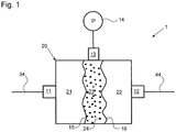
- FIGS. 1 and 2 A preferred embodiment of a device 1 according to the invention and of a system 100 according to the invention will be described below with reference to FIGS. 1 and 2.
- Fig. 2 shows a plant 100, which comprises a flow component 50, which is traversed by a fluid.
- the fluid may in principle be any liquid or gas.
- the flow component 50 should be protected from pulsations of the fluid. This is required, for example, when the flow component 50 is a flow meter.
- the pulsations may in particular be caused by a pump 60, which conveys the fluid via a supply line 31, 32 to the flow component 50.
- a device 1 is provided. This is connected in parallel to the flow component 50. That is, the supply line 31 divides at a branch 36 into two sections or line sections, of which one line section 32 leads fluid to the flow component 50, while the other line section 34 leads fluid to the device 1.
- a discharge line 41 has a branching / joining 46, at which a line section 44 of the device 1 and a line section 42 of the throughflow component 50 meet.
- the device 1 does not produce a continuous fluid connection. If the flow component 50 is a flow meter, consequently its flow measurement is not falsified by the device 1. However, in order to protect against pulsations, the device 1 forwards pulses of the fluid, that is to say from the line section 34 to the line section 44. As a result, pulsations are largely passed to the flow component 50 past. Preferably, the device 1 also leads to a damping of the pulsation.
- the device 1 has a first and a second fluid connection 11 and 12, which are connected to the line section 34 of the supply line and the line section 44 of the discharge line.
- the device 1 comprises an inner space 20, in which fluid from the two ports 11 and 12 can enter.
- the interior 20 may be cylindrical, with the terminals 11 and 12 are located at the end faces.
- the interior 20 does not provide fluid communication between the ports 11 and 12. Rather, two release agents 15 and 16 in the interior 20 are present. As a result, the interior 20 is divided into a chamber 21 connected to the connection 11 and a separate chamber 22 connected to the termination 12.
- the separating means 15 and 16 are movable, whereby they can forward pulsations and / or attenuate.
- the damping effect can be enhanced by a higher number of successively arranged release agent 15, 16. Between adjacent separating means 15, 16 a central portion 23 is formed in each case. In this there is a damping fluid 24. Pulsations are therefore transmitted from the fluid in the first chamber 21 via the release agent 15 to the damping fluid 24 and from there via the release agent 16 to the fluid in the second chamber 22 and attenuated. Even with pulsations in the reverse direction, there is a damped transmission.
- a central terminal 13 is preferably present at the central portion 23.
- the damping fluid 24 can be filled.
- a measuring device 14 can be connected, which monitors a property, for example the pressure, of the damping fluid 24.
- the shape of the feed line 31, 32, 34 is significant.
- the branch 36 of the supply line 31 may be designed so that a fluid forwarding to the device 1 in the axial direction 35, that is in the main direction of flow, takes place.
- the flow-through component 50 can be reached by the fluid flow at the branch 36 undergoing a change in direction corresponding to the arrow 33.
- the branching / joining 46 of the discharge line has no or only a slight bend toward the device 1, while an angle of, for example, 90 ° is present for the throughflow component 50.
- Pulsations can also propagate upstream from the discharge line 41. This can occur, for example, by switching a valve 70 in the discharge line 41.
- the flow resistance in the line section 32 to the flow component 50 can be increased.
- a throttle or orifice 80 may be provided in the conduit section 32.
- a throughflow component to be protected can also be applied to the in-flow component Fig. 2 represented location of the valve 70 in the discharge line 41 are located.
- a flow component 50 may then preferably be provided a throttle. Because such a system causes a pulsation damping in the discharge line 41, also a serial arrangement the device 1 according to the invention and a throughflow component to be protected should be advantageous.
- the device according to the invention is relatively space-saving, in particular compared to storing pulsation dampers. As a result, it can be easily and cost-effectively integrated into existing systems.
Landscapes
- Engineering & Computer Science (AREA)
- General Engineering & Computer Science (AREA)
- Mechanical Engineering (AREA)
- Chemical & Material Sciences (AREA)
- Combustion & Propulsion (AREA)
- Pipe Accessories (AREA)
- Reciprocating Pumps (AREA)
Claims (10)
- Dispositif de protection contre les pulsations de fluide avec- un premier raccord de fluide (11),- un second raccord de fluide (12) et- un espace intérieur (20) placé entre le premier et le second raccord de fluide (11, 12),caractérisé en ce que- au moins deux moyens de séparation (15, 16) élastiques formés de manière identique se trouvant l'un derrière l'autre sont prévus dans l'espace intérieur (20), lesquels séparent par voie fluidique l'espace intérieur (20) en au moins une première chambre (21) qui est tournée vers le premier raccord de fluide (11), et une seconde chambre (22) qui est tournée vers le second raccord de fluide (12) et empêche ainsi une circulation à travers le dispositif,- entre les au moins deux moyens de séparation (15, 16) est formée une chambre centrale (23) qui se trouve entre la première et la seconde chambre (21, 22) et est séparée par voie fluidique de celles-ci, et- les moyens de séparation (15, 16) sont mobiles indépendamment l'un de l'autre pour l'amortissement ou la transmission d'une pulsation de fluide incidente.
- Dispositif selon la revendication 1,
caractérisé en ce que
les moyens de séparation mobiles (15, 16) sont coulissants. - Dispositif selon la revendication 2,
caractérisé en ce que
la chambre centrale (23) est remplie avec un fluide d'amortissement (24) pour l'amortissement de pulsations de fluide qui agissent sur un des moyens de séparation mobiles (15, 16). - Dispositif selon la revendication 3,
caractérisé en ce que
un dispositif de mesure (14) est prévu au niveau de la chambre centrale (23) pour la détection d'une propriété du fluide d'amortissement (24). - Installation avec- un composant de passage (50) qui peut être traversé par un fluide,- une conduite d'alimentation (31) pour l'acheminement du fluide vers le composant de passage (50) et- une conduite d'évacuation (41) pour la transmission du fluide du composant de passage (50),caractérisée en ce que
un dispositif (1) selon l'une quelconque des revendications 1 à 4 est prévu et
le dispositif (1) est relié à la conduite d'alimentation (31) et à la conduite d'évacuation (41) parallèlement au composant de passage (50). - Installation selon la revendication 5,
caractérisée en ce que
la conduite d'alimentation (31) présente une bifurcation (36) sur laquelle une section principale (34) de la conduite d'alimentation (31) mène dans le sens d'afflux principal du fluide au dispositif (1) et une section accessoire (32) de la conduite d'alimentation (31) mène dans un sens coudé au composant de passage (50). - Installation selon la revendication 5 ou 6,
caractérisée en ce que
la conduite d'évacuation (41) présente une bifurcation (46) sur laquelle une section principale (44) de la conduite d'évacuation (41) est reliée au dispositif (1) et une section accessoire (42) de la conduite d'évacuation (41) est reliée dans un sens coudé au composant de passage (50). - Installation selon la revendication 6 ou 7,
caractérisée en ce que
des moyens (80) sont prévus pour la génération d'une chute de pression sur la section accessoire (32) de la conduite d'alimentation (31) au composant de passage (50). - Installation selon l'une quelconque des revendications 5 à 8,
caractérisée en ce que
le composant de passage est un diaphragme ou élément d'étranglement pour la génération d'une chute de pression. - Procédé de protection contre des pulsations de fluide,
dans lequel un fluide est acheminé d'une conduite d'alimentation (31) vers un composant de passage (50) et au-delà vers une conduite d'évacuation (41),
dans lequel le fluide est acheminé vers un dispositif (1) pour la protection contre des pulsations de fluide, qui est relié par voie fluidique au composant de passage (50), dans lequel le dispositif (1) pour la protection contre des pulsations de fluide est relié à la conduite d'alimentation (31) et à la conduite d'évacuation (41) parallèlement au composant de passage (50),
caractérisé en ce que- dans un espace intérieur (20) du dispositif (1) au moins deux moyens de séparation (15, 16) mobiles indépendamment l'un de l'autre sont prévus, lesquels séparent par voie fluidique l'espace intérieur (20) en au moins une première chambre (21) et une seconde chambre (22), dans lequel la première chambre (21) est reliée par voie fluidique à la conduite d'alimentation (31) et la seconde chambre (22) est reliée par voie fluidique à la conduite d'évacuation (41),- les au moins deux moyens de séparation mobiles sont réalisés de manière élastique et de manière identique et se trouvent l'un derrière l'autre,- une chambre centrale (23) est formée entre les au moins deux moyens de séparation (15, 16) mobiles qui se trouve entre la première et la seconde chambre (21, 22) et est séparée par voie fluidique de celles-ci, et- lors d'une pulsation de fluide dans la conduite d'alimentation (31) ou dans la conduite d'évacuation (41) une impulsion est transmise par l'intermédiaire des moyens de séparation (15, 16) mobiles mais aucune circulation du fluide à travers le dispositif (1) n'est permise.
Priority Applications (1)
| Application Number | Priority Date | Filing Date | Title |
|---|---|---|---|
| EP14162015.3A EP2924330B1 (fr) | 2014-03-27 | 2014-03-27 | Dispositif et procédé de protection contre les pulsations de fluide |
Applications Claiming Priority (1)
| Application Number | Priority Date | Filing Date | Title |
|---|---|---|---|
| EP14162015.3A EP2924330B1 (fr) | 2014-03-27 | 2014-03-27 | Dispositif et procédé de protection contre les pulsations de fluide |
Publications (2)
| Publication Number | Publication Date |
|---|---|
| EP2924330A1 EP2924330A1 (fr) | 2015-09-30 |
| EP2924330B1 true EP2924330B1 (fr) | 2018-01-31 |
Family
ID=50389881
Family Applications (1)
| Application Number | Title | Priority Date | Filing Date |
|---|---|---|---|
| EP14162015.3A Not-in-force EP2924330B1 (fr) | 2014-03-27 | 2014-03-27 | Dispositif et procédé de protection contre les pulsations de fluide |
Country Status (1)
| Country | Link |
|---|---|
| EP (1) | EP2924330B1 (fr) |
Citations (2)
| Publication number | Priority date | Publication date | Assignee | Title |
|---|---|---|---|---|
| DE2000836B1 (de) * | 1970-01-09 | 1971-03-25 | Geraetebau Gmbh & Co Kg Deutsc | Kompensationsvorrichtung fuer Fluessigkeits-Mengenmesser von Pumpenzapfanlagen |
| EP2112368A2 (fr) * | 2008-04-25 | 2009-10-28 | Hitachi Ltd. | Mécanisme de retenue de pulsation de pression de carburant et pompe à carburant à haute pression de moteur à combustion interne avec ce mécanisme |
Family Cites Families (3)
| Publication number | Priority date | Publication date | Assignee | Title |
|---|---|---|---|---|
| US2731984A (en) * | 1956-01-24 | everett | ||
| US2592613A (en) * | 1947-06-07 | 1952-04-15 | Snyder Oil Tool Corp | Self-compensating accumulator |
| US3672402A (en) * | 1970-09-14 | 1972-06-27 | Eaton Yale & Towne | Automatic precharge adjuster |
-
2014
- 2014-03-27 EP EP14162015.3A patent/EP2924330B1/fr not_active Not-in-force
Patent Citations (2)
| Publication number | Priority date | Publication date | Assignee | Title |
|---|---|---|---|---|
| DE2000836B1 (de) * | 1970-01-09 | 1971-03-25 | Geraetebau Gmbh & Co Kg Deutsc | Kompensationsvorrichtung fuer Fluessigkeits-Mengenmesser von Pumpenzapfanlagen |
| EP2112368A2 (fr) * | 2008-04-25 | 2009-10-28 | Hitachi Ltd. | Mécanisme de retenue de pulsation de pression de carburant et pompe à carburant à haute pression de moteur à combustion interne avec ce mécanisme |
Also Published As
| Publication number | Publication date |
|---|---|
| EP2924330A1 (fr) | 2015-09-30 |
Similar Documents
| Publication | Publication Date | Title |
|---|---|---|
| EP2480807A1 (fr) | Soupape anti-retour à deux éléments de fermeture | |
| WO2001018443A1 (fr) | Dispositif pour reduire des pulsations de pression dans des conduites hydrauliques | |
| DE102010043439A1 (de) | Kraftstoffeinspritzsystem einer Brennkraftmaschine | |
| EP3093532A2 (fr) | Systeme hydraulique de vehicule automobile | |
| EP2614246A1 (fr) | Bloc d'accumulation de carburant pour l'essai de composants haute pression de dispositifs d'injection de combustible | |
| DE102013008781A1 (de) | Verfahren zum Betrieb eines Ultraschalldurchflusszählers sowie Ultraschalldurchflusszähler | |
| WO2008017544A1 (fr) | Système d'injection de carburant avec un amortisseur de vibrations de pression | |
| EP2924330B1 (fr) | Dispositif et procédé de protection contre les pulsations de fluide | |
| DE102017001317B3 (de) | Hubkolbenpumpe mit aktivem Dämpfer und Verfahren zum Betrieb der Hubkolbenpumpe | |
| DE102006016937B4 (de) | Hydraulischer Pulsationsdämpfer | |
| DE102014223788A1 (de) | Drucksteuereinrichtung insbesondere für eine ein Fluid fördernde Hochdruckpumpe | |
| DE102014214886B4 (de) | Doppeltwirkendes Rückschlagventil | |
| WO2021078727A1 (fr) | Cylindre hydrostatique avec accumulateur de pression de gaz | |
| EP1757817B1 (fr) | Arrangement de valve pour contrôler une soupape à fermeture rapide de turbine à gaz ou à vapeur | |
| DE102011111579A1 (de) | Fluidfördersystem zur Förderung eines Fluids zu mindestens einem Verbraucher | |
| AT408899B (de) | Dämpfungsanordnung für fluidsysteme | |
| DE102012213564A1 (de) | Schmiermittelsystem | |
| DE102018117111A1 (de) | Pleuel für eine Brennkraftmaschine mit variabler Verdichtung | |
| DE102013000338A1 (de) | Pulsationsdämpfer | |
| WO2020020419A1 (fr) | Pompe pour un véhicule à moteur | |
| DE102013004437A1 (de) | Hydraulisches Sicherheits- und Bewegungsregelsystem | |
| DE102004018928A1 (de) | Schwingungsdämpfer für ein Hydrauliksystem | |
| DE102014222417B4 (de) | Kraftstofffördereinheit | |
| DE102010064192A1 (de) | Druck-Schaltventil für ein Kraftstoffeinspritzsystem einer Brennkraftmaschine | |
| DE102011002692A1 (de) | Hydraulikspeichersystem |
Legal Events
| Date | Code | Title | Description |
|---|---|---|---|
| PUAI | Public reference made under article 153(3) epc to a published international application that has entered the european phase |
Free format text: ORIGINAL CODE: 0009012 |
|
| AK | Designated contracting states |
Kind code of ref document: A1 Designated state(s): AL AT BE BG CH CY CZ DE DK EE ES FI FR GB GR HR HU IE IS IT LI LT LU LV MC MK MT NL NO PL PT RO RS SE SI SK SM TR |
|
| AX | Request for extension of the european patent |
Extension state: BA ME |
|
| 17P | Request for examination filed |
Effective date: 20160311 |
|
| RBV | Designated contracting states (corrected) |
Designated state(s): AL AT BE BG CH CY CZ DE DK EE ES FI FR GB GR HR HU IE IS IT LI LT LU LV MC MK MT NL NO PL PT RO RS SE SI SK SM TR |
|
| RIC1 | Information provided on ipc code assigned before grant |
Ipc: F17D 1/20 20060101ALI20170817BHEP Ipc: F16L 55/04 20060101AFI20170817BHEP Ipc: F16L 55/045 20060101ALI20170817BHEP Ipc: F02M 55/04 20060101ALI20170817BHEP Ipc: F02M 37/00 20060101ALI20170817BHEP Ipc: F16L 55/053 20060101ALI20170817BHEP |
|
| GRAP | Despatch of communication of intention to grant a patent |
Free format text: ORIGINAL CODE: EPIDOSNIGR1 |
|
| STAA | Information on the status of an ep patent application or granted ep patent |
Free format text: STATUS: GRANT OF PATENT IS INTENDED |
|
| INTG | Intention to grant announced |
Effective date: 20171006 |
|
| GRAS | Grant fee paid |
Free format text: ORIGINAL CODE: EPIDOSNIGR3 |
|
| GRAA | (expected) grant |
Free format text: ORIGINAL CODE: 0009210 |
|
| STAA | Information on the status of an ep patent application or granted ep patent |
Free format text: STATUS: THE PATENT HAS BEEN GRANTED |
|
| AK | Designated contracting states |
Kind code of ref document: B1 Designated state(s): AL AT BE BG CH CY CZ DE DK EE ES FI FR GB GR HR HU IE IS IT LI LT LU LV MC MK MT NL NO PL PT RO RS SE SI SK SM TR |
|
| REG | Reference to a national code |
Ref country code: GB Ref legal event code: FG4D Free format text: NOT ENGLISH Ref country code: CH Ref legal event code: EP |
|
| REG | Reference to a national code |
Ref country code: AT Ref legal event code: REF Ref document number: 967713 Country of ref document: AT Kind code of ref document: T Effective date: 20180215 |
|
| REG | Reference to a national code |
Ref country code: IE Ref legal event code: FG4D Free format text: LANGUAGE OF EP DOCUMENT: GERMAN |
|
| REG | Reference to a national code |
Ref country code: DE Ref legal event code: R096 Ref document number: 502014007056 Country of ref document: DE |
|
| REG | Reference to a national code |
Ref country code: NL Ref legal event code: MP Effective date: 20180131 |
|
| REG | Reference to a national code |
Ref country code: LT Ref legal event code: MG4D |
|
| PG25 | Lapsed in a contracting state [announced via postgrant information from national office to epo] |
Ref country code: NO Free format text: LAPSE BECAUSE OF FAILURE TO SUBMIT A TRANSLATION OF THE DESCRIPTION OR TO PAY THE FEE WITHIN THE PRESCRIBED TIME-LIMIT Effective date: 20180430 Ref country code: LT Free format text: LAPSE BECAUSE OF FAILURE TO SUBMIT A TRANSLATION OF THE DESCRIPTION OR TO PAY THE FEE WITHIN THE PRESCRIBED TIME-LIMIT Effective date: 20180131 Ref country code: ES Free format text: LAPSE BECAUSE OF FAILURE TO SUBMIT A TRANSLATION OF THE DESCRIPTION OR TO PAY THE FEE WITHIN THE PRESCRIBED TIME-LIMIT Effective date: 20180131 Ref country code: NL Free format text: LAPSE BECAUSE OF FAILURE TO SUBMIT A TRANSLATION OF THE DESCRIPTION OR TO PAY THE FEE WITHIN THE PRESCRIBED TIME-LIMIT Effective date: 20180131 Ref country code: HR Free format text: LAPSE BECAUSE OF FAILURE TO SUBMIT A TRANSLATION OF THE DESCRIPTION OR TO PAY THE FEE WITHIN THE PRESCRIBED TIME-LIMIT Effective date: 20180131 Ref country code: FI Free format text: LAPSE BECAUSE OF FAILURE TO SUBMIT A TRANSLATION OF THE DESCRIPTION OR TO PAY THE FEE WITHIN THE PRESCRIBED TIME-LIMIT Effective date: 20180131 |
|
| PGFP | Annual fee paid to national office [announced via postgrant information from national office to epo] |
Ref country code: DE Payment date: 20180508 Year of fee payment: 5 |
|
| PG25 | Lapsed in a contracting state [announced via postgrant information from national office to epo] |
Ref country code: IS Free format text: LAPSE BECAUSE OF FAILURE TO SUBMIT A TRANSLATION OF THE DESCRIPTION OR TO PAY THE FEE WITHIN THE PRESCRIBED TIME-LIMIT Effective date: 20180531 Ref country code: PL Free format text: LAPSE BECAUSE OF FAILURE TO SUBMIT A TRANSLATION OF THE DESCRIPTION OR TO PAY THE FEE WITHIN THE PRESCRIBED TIME-LIMIT Effective date: 20180131 Ref country code: GR Free format text: LAPSE BECAUSE OF FAILURE TO SUBMIT A TRANSLATION OF THE DESCRIPTION OR TO PAY THE FEE WITHIN THE PRESCRIBED TIME-LIMIT Effective date: 20180501 Ref country code: LV Free format text: LAPSE BECAUSE OF FAILURE TO SUBMIT A TRANSLATION OF THE DESCRIPTION OR TO PAY THE FEE WITHIN THE PRESCRIBED TIME-LIMIT Effective date: 20180131 Ref country code: SE Free format text: LAPSE BECAUSE OF FAILURE TO SUBMIT A TRANSLATION OF THE DESCRIPTION OR TO PAY THE FEE WITHIN THE PRESCRIBED TIME-LIMIT Effective date: 20180131 Ref country code: RS Free format text: LAPSE BECAUSE OF FAILURE TO SUBMIT A TRANSLATION OF THE DESCRIPTION OR TO PAY THE FEE WITHIN THE PRESCRIBED TIME-LIMIT Effective date: 20180131 Ref country code: BG Free format text: LAPSE BECAUSE OF FAILURE TO SUBMIT A TRANSLATION OF THE DESCRIPTION OR TO PAY THE FEE WITHIN THE PRESCRIBED TIME-LIMIT Effective date: 20180430 |
|
| PGFP | Annual fee paid to national office [announced via postgrant information from national office to epo] |
Ref country code: IT Payment date: 20180522 Year of fee payment: 5 |
|
| PG25 | Lapsed in a contracting state [announced via postgrant information from national office to epo] |
Ref country code: MT Free format text: LAPSE BECAUSE OF FAILURE TO SUBMIT A TRANSLATION OF THE DESCRIPTION OR TO PAY THE FEE WITHIN THE PRESCRIBED TIME-LIMIT Effective date: 20180131 |
|
| PG25 | Lapsed in a contracting state [announced via postgrant information from national office to epo] |
Ref country code: EE Free format text: LAPSE BECAUSE OF FAILURE TO SUBMIT A TRANSLATION OF THE DESCRIPTION OR TO PAY THE FEE WITHIN THE PRESCRIBED TIME-LIMIT Effective date: 20180131 Ref country code: AL Free format text: LAPSE BECAUSE OF FAILURE TO SUBMIT A TRANSLATION OF THE DESCRIPTION OR TO PAY THE FEE WITHIN THE PRESCRIBED TIME-LIMIT Effective date: 20180131 Ref country code: RO Free format text: LAPSE BECAUSE OF FAILURE TO SUBMIT A TRANSLATION OF THE DESCRIPTION OR TO PAY THE FEE WITHIN THE PRESCRIBED TIME-LIMIT Effective date: 20180131 |
|
| REG | Reference to a national code |
Ref country code: CH Ref legal event code: PL |
|
| REG | Reference to a national code |
Ref country code: DE Ref legal event code: R097 Ref document number: 502014007056 Country of ref document: DE |
|
| PG25 | Lapsed in a contracting state [announced via postgrant information from national office to epo] |
Ref country code: CZ Free format text: LAPSE BECAUSE OF FAILURE TO SUBMIT A TRANSLATION OF THE DESCRIPTION OR TO PAY THE FEE WITHIN THE PRESCRIBED TIME-LIMIT Effective date: 20180131 Ref country code: SM Free format text: LAPSE BECAUSE OF FAILURE TO SUBMIT A TRANSLATION OF THE DESCRIPTION OR TO PAY THE FEE WITHIN THE PRESCRIBED TIME-LIMIT Effective date: 20180131 Ref country code: DK Free format text: LAPSE BECAUSE OF FAILURE TO SUBMIT A TRANSLATION OF THE DESCRIPTION OR TO PAY THE FEE WITHIN THE PRESCRIBED TIME-LIMIT Effective date: 20180131 Ref country code: SK Free format text: LAPSE BECAUSE OF FAILURE TO SUBMIT A TRANSLATION OF THE DESCRIPTION OR TO PAY THE FEE WITHIN THE PRESCRIBED TIME-LIMIT Effective date: 20180131 Ref country code: MC Free format text: LAPSE BECAUSE OF FAILURE TO SUBMIT A TRANSLATION OF THE DESCRIPTION OR TO PAY THE FEE WITHIN THE PRESCRIBED TIME-LIMIT Effective date: 20180131 |
|
| PLBE | No opposition filed within time limit |
Free format text: ORIGINAL CODE: 0009261 |
|
| STAA | Information on the status of an ep patent application or granted ep patent |
Free format text: STATUS: NO OPPOSITION FILED WITHIN TIME LIMIT |
|
| REG | Reference to a national code |
Ref country code: BE Ref legal event code: MM Effective date: 20180331 |
|
| GBPC | Gb: european patent ceased through non-payment of renewal fee |
Effective date: 20180430 |
|
| REG | Reference to a national code |
Ref country code: IE Ref legal event code: MM4A |
|
| PG25 | Lapsed in a contracting state [announced via postgrant information from national office to epo] |
Ref country code: LU Free format text: LAPSE BECAUSE OF NON-PAYMENT OF DUE FEES Effective date: 20180327 |
|
| 26N | No opposition filed |
Effective date: 20181102 |
|
| PG25 | Lapsed in a contracting state [announced via postgrant information from national office to epo] |
Ref country code: IE Free format text: LAPSE BECAUSE OF NON-PAYMENT OF DUE FEES Effective date: 20180327 |
|
| PG25 | Lapsed in a contracting state [announced via postgrant information from national office to epo] |
Ref country code: BE Free format text: LAPSE BECAUSE OF NON-PAYMENT OF DUE FEES Effective date: 20180331 Ref country code: CH Free format text: LAPSE BECAUSE OF NON-PAYMENT OF DUE FEES Effective date: 20180331 Ref country code: LI Free format text: LAPSE BECAUSE OF NON-PAYMENT OF DUE FEES Effective date: 20180331 Ref country code: SI Free format text: LAPSE BECAUSE OF FAILURE TO SUBMIT A TRANSLATION OF THE DESCRIPTION OR TO PAY THE FEE WITHIN THE PRESCRIBED TIME-LIMIT Effective date: 20180131 Ref country code: GB Free format text: LAPSE BECAUSE OF NON-PAYMENT OF DUE FEES Effective date: 20180430 |
|
| PG25 | Lapsed in a contracting state [announced via postgrant information from national office to epo] |
Ref country code: FR Free format text: LAPSE BECAUSE OF NON-PAYMENT OF DUE FEES Effective date: 20180331 |
|
| REG | Reference to a national code |
Ref country code: DE Ref legal event code: R119 Ref document number: 502014007056 Country of ref document: DE |
|
| PG25 | Lapsed in a contracting state [announced via postgrant information from national office to epo] |
Ref country code: DE Free format text: LAPSE BECAUSE OF NON-PAYMENT OF DUE FEES Effective date: 20191001 |
|
| PG25 | Lapsed in a contracting state [announced via postgrant information from national office to epo] |
Ref country code: IT Free format text: LAPSE BECAUSE OF NON-PAYMENT OF DUE FEES Effective date: 20190327 |
|
| PG25 | Lapsed in a contracting state [announced via postgrant information from national office to epo] |
Ref country code: TR Free format text: LAPSE BECAUSE OF FAILURE TO SUBMIT A TRANSLATION OF THE DESCRIPTION OR TO PAY THE FEE WITHIN THE PRESCRIBED TIME-LIMIT Effective date: 20180131 |
|
| PG25 | Lapsed in a contracting state [announced via postgrant information from national office to epo] |
Ref country code: PT Free format text: LAPSE BECAUSE OF FAILURE TO SUBMIT A TRANSLATION OF THE DESCRIPTION OR TO PAY THE FEE WITHIN THE PRESCRIBED TIME-LIMIT Effective date: 20180131 |
|
| PG25 | Lapsed in a contracting state [announced via postgrant information from national office to epo] |
Ref country code: HU Free format text: LAPSE BECAUSE OF FAILURE TO SUBMIT A TRANSLATION OF THE DESCRIPTION OR TO PAY THE FEE WITHIN THE PRESCRIBED TIME-LIMIT; INVALID AB INITIO Effective date: 20140327 Ref country code: MK Free format text: LAPSE BECAUSE OF NON-PAYMENT OF DUE FEES Effective date: 20180131 Ref country code: CY Free format text: LAPSE BECAUSE OF FAILURE TO SUBMIT A TRANSLATION OF THE DESCRIPTION OR TO PAY THE FEE WITHIN THE PRESCRIBED TIME-LIMIT Effective date: 20180131 |
|
| REG | Reference to a national code |
Ref country code: AT Ref legal event code: MM01 Ref document number: 967713 Country of ref document: AT Kind code of ref document: T Effective date: 20190327 |
|
| PG25 | Lapsed in a contracting state [announced via postgrant information from national office to epo] |
Ref country code: AT Free format text: LAPSE BECAUSE OF NON-PAYMENT OF DUE FEES Effective date: 20190327 |